EP0362997A1 - Burner nozzle assembly tip - Google Patents
Burner nozzle assembly tip Download PDFInfo
- Publication number
- EP0362997A1 EP0362997A1 EP89308442A EP89308442A EP0362997A1 EP 0362997 A1 EP0362997 A1 EP 0362997A1 EP 89308442 A EP89308442 A EP 89308442A EP 89308442 A EP89308442 A EP 89308442A EP 0362997 A1 EP0362997 A1 EP 0362997A1
- Authority
- EP
- European Patent Office
- Prior art keywords
- liner
- nozzle assembly
- burner nozzle
- tip
- retaining ring
- Prior art date
- Legal status (The legal status is an assumption and is not a legal conclusion. Google has not performed a legal analysis and makes no representation as to the accuracy of the status listed.)
- Withdrawn
Links
Images
Classifications
-
- B—PERFORMING OPERATIONS; TRANSPORTING
- B05—SPRAYING OR ATOMISING IN GENERAL; APPLYING FLUENT MATERIALS TO SURFACES, IN GENERAL
- B05B—SPRAYING APPARATUS; ATOMISING APPARATUS; NOZZLES
- B05B1/00—Nozzles, spray heads or other outlets, with or without auxiliary devices such as valves, heating means
-
- C—CHEMISTRY; METALLURGY
- C09—DYES; PAINTS; POLISHES; NATURAL RESINS; ADHESIVES; COMPOSITIONS NOT OTHERWISE PROVIDED FOR; APPLICATIONS OF MATERIALS NOT OTHERWISE PROVIDED FOR
- C09C—TREATMENT OF INORGANIC MATERIALS, OTHER THAN FIBROUS FILLERS, TO ENHANCE THEIR PIGMENTING OR FILLING PROPERTIES ; PREPARATION OF CARBON BLACK ; PREPARATION OF INORGANIC MATERIALS WHICH ARE NO SINGLE CHEMICAL COMPOUNDS AND WHICH ARE MAINLY USED AS PIGMENTS OR FILLERS
- C09C1/00—Treatment of specific inorganic materials other than fibrous fillers; Preparation of carbon black
- C09C1/44—Carbon
- C09C1/48—Carbon black
- C09C1/50—Furnace black ; Preparation thereof
-
- C—CHEMISTRY; METALLURGY
- C10—PETROLEUM, GAS OR COKE INDUSTRIES; TECHNICAL GASES CONTAINING CARBON MONOXIDE; FUELS; LUBRICANTS; PEAT
- C10J—PRODUCTION OF PRODUCER GAS, WATER-GAS, SYNTHESIS GAS FROM SOLID CARBONACEOUS MATERIAL, OR MIXTURES CONTAINING THESE GASES; CARBURETTING AIR OR OTHER GASES
- C10J3/00—Production of combustible gases containing carbon monoxide from solid carbonaceous fuels
- C10J3/46—Gasification of granular or pulverulent flues in suspension
- C10J3/48—Apparatus; Plants
- C10J3/50—Fuel charging devices
- C10J3/506—Fuel charging devices for entrained flow gasifiers
-
- F—MECHANICAL ENGINEERING; LIGHTING; HEATING; WEAPONS; BLASTING
- F23—COMBUSTION APPARATUS; COMBUSTION PROCESSES
- F23D—BURNERS
- F23D1/00—Burners for combustion of pulverulent fuel
- F23D1/005—Burners for combustion of pulverulent fuel burning a mixture of pulverulent fuel delivered as a slurry, i.e. comprising a carrying liquid
-
- F—MECHANICAL ENGINEERING; LIGHTING; HEATING; WEAPONS; BLASTING
- F23—COMBUSTION APPARATUS; COMBUSTION PROCESSES
- F23D—BURNERS
- F23D11/00—Burners using a direct spraying action of liquid droplets or vaporised liquid into the combustion space
- F23D11/36—Details, e.g. burner cooling means, noise reduction means
- F23D11/38—Nozzles; Cleaning devices therefor
-
- B—PERFORMING OPERATIONS; TRANSPORTING
- B01—PHYSICAL OR CHEMICAL PROCESSES OR APPARATUS IN GENERAL
- B01J—CHEMICAL OR PHYSICAL PROCESSES, e.g. CATALYSIS OR COLLOID CHEMISTRY; THEIR RELEVANT APPARATUS
- B01J19/00—Chemical, physical or physico-chemical processes in general; Their relevant apparatus
-
- C—CHEMISTRY; METALLURGY
- C10—PETROLEUM, GAS OR COKE INDUSTRIES; TECHNICAL GASES CONTAINING CARBON MONOXIDE; FUELS; LUBRICANTS; PEAT
- C10J—PRODUCTION OF PRODUCER GAS, WATER-GAS, SYNTHESIS GAS FROM SOLID CARBONACEOUS MATERIAL, OR MIXTURES CONTAINING THESE GASES; CARBURETTING AIR OR OTHER GASES
- C10J2200/00—Details of gasification apparatus
- C10J2200/15—Details of feeding means
- C10J2200/152—Nozzles or lances for introducing gas, liquids or suspensions
-
- C—CHEMISTRY; METALLURGY
- C10—PETROLEUM, GAS OR COKE INDUSTRIES; TECHNICAL GASES CONTAINING CARBON MONOXIDE; FUELS; LUBRICANTS; PEAT
- C10J—PRODUCTION OF PRODUCER GAS, WATER-GAS, SYNTHESIS GAS FROM SOLID CARBONACEOUS MATERIAL, OR MIXTURES CONTAINING THESE GASES; CARBURETTING AIR OR OTHER GASES
- C10J2300/00—Details of gasification processes
- C10J2300/12—Heating the gasifier
- C10J2300/1223—Heating the gasifier by burners
-
- F—MECHANICAL ENGINEERING; LIGHTING; HEATING; WEAPONS; BLASTING
- F23—COMBUSTION APPARATUS; COMBUSTION PROCESSES
- F23D—BURNERS
- F23D2201/00—Burners adapted for particulate solid or pulverulent fuels
- F23D2201/10—Nozzle tips
-
- F—MECHANICAL ENGINEERING; LIGHTING; HEATING; WEAPONS; BLASTING
- F23—COMBUSTION APPARATUS; COMBUSTION PROCESSES
- F23D—BURNERS
- F23D2201/00—Burners adapted for particulate solid or pulverulent fuels
- F23D2201/30—Wear protection
-
- Y—GENERAL TAGGING OF NEW TECHNOLOGICAL DEVELOPMENTS; GENERAL TAGGING OF CROSS-SECTIONAL TECHNOLOGIES SPANNING OVER SEVERAL SECTIONS OF THE IPC; TECHNICAL SUBJECTS COVERED BY FORMER USPC CROSS-REFERENCE ART COLLECTIONS [XRACs] AND DIGESTS
- Y10—TECHNICAL SUBJECTS COVERED BY FORMER USPC
- Y10S—TECHNICAL SUBJECTS COVERED BY FORMER USPC CROSS-REFERENCE ART COLLECTIONS [XRACs] AND DIGESTS
- Y10S48/00—Gas: heating and illuminating
- Y10S48/07—Slurry
Definitions
- This invention relates to a two-fluid nozzle for atomizing a liquid with a gas which includes a protector for the nozzle tip.
- a protector for the nozzle tip In many applications, such as boilers, furnaces and coal gasification reactors, the harsh combustion environment unduly shortens nozzle life.
- the tip of the burner nozzle is most especially subjected to the greatest thermal stress.
- Thermal stress is defined as the mechanical force caused by expansion because of an increase in temperature of a body or portion thereof. Thermal stress can be very large especially at areas of high thermal gradient, for example, at the discharge outlet where the atomized fluids exit the nozzle into the furnace or combustion zone and the geometry of the nozzle changes from contacting internal temperatures to contacting combustion zone temperatures over a very short physical distance.
- the present invention seeks to provide a nozzle which is highly efficient in atomizing the gas-liquid mixture, and which is more stable and durable to the various stresses of the harsh environment of use without changing the burner configuration greatly, or increasing the difficulty of manufacture by working with exotic ceramic or refractory materials.
- the present invention provides a burner nozzle assembly tip connected to the downstream end of a burner nozzle assembly, in which said burner nozzle assembly has at least two conduits for atomization of a liquid selected from liquid carbonaceous materials and a slurry of carbonaceous material with an oxidizing gas, said two conduits including at least a central and annular conduit containing said liquid and said gas, respectively, and which converge at an internal mixing zone to provide efficient mixing for the liquid fuel and oxidizing gas for discharge through a discharge orifice and to a combustion zone for combustion at a relatively high temperature
- said tip comprising a central outlet having a shoulder at its upstream end and a thermally resistant metal alloy heat shield attached to a retaining ring which is located upstream of said shoulder and in contact therewith and said heat shield comprising a cylindrical liner having an upstream end and a downstream end, the upstream end of which has a diameter less than said outlet, said liner diverging outwardly from the central longitudinal axis of said burner nozzle assembly to a diameter larger than said
- the burner nozzle assembly tip is preferably of a heat resistant metal alloy, such as a nickel-chromium-steel alloy and, more preferably, for example, Inconel alloys such as Incoloy 800H, Incoloy 800HT, Type 310 Stainless steel, or Incoloy MA956 (Incoloy is a trademark of INCO Alloys International, Inc.).
- the space between the nozzle and the liner of the nozzle can be packed with a compressible, heat- insulating material, such as, graphite, metal gauze, or tape packing.
- a preferred nozzle tip of this invention includes a two-piece heat shield in which the liner and retaining ring are threadedly connected and, more preferably, being unitized by a locking pin to prevent the parts from unscrewing and disengaging.
- the burner nozzle of this invention can be useful in any application requiring the use of a burner nozzle which is subject to the thermal, mechanical and chemical stresses of harsh environments, such as furnaces or coal gasification reactors in atomizing a two-fluid system, such as oxygen, air or oxygen-containing gas and liquid hydrocarbonaceous or solid carbonaceous slurried fuels.
- a two-fluid system such as oxygen, air or oxygen-containing gas and liquid hydrocarbonaceous or solid carbonaceous slurried fuels.
- a two-fluid nozzle which is adjustable to provide a substantially constant mixing energy is disclosed.
- the nozzle is more specifically defined and includes a microprocessor to calculate the mixing energy from the pressure and mass flow values of the liquid and gas fed to the nozzle as measured by the appropriate sensing devices.
- the problem solved by the present invention is to prevent the burner face from failing by cracking because of thermal stress from the heat produced in the furnace or gasification reactor. This is accomplished by the protective tip or heat shield structure and the materials employed in the structure provided.
- the invention provides a tip for a burner nozzle such as that described in U.S. 4,705,535 and a shield or protecting tip which prevents direct contact and heat conduction for the burner assembly from the two-fluid mixture and its combustion products during combustion.
- the protecting tip is coaxial with the central longitudinal axis of the burner assembly and provides an unobstructed central conduit from the discharge orifice of the burner assembly to the reactor or furnace combustion zone.
- the protecting tip includes a cap portion and a heat shield portion. Because the nozzle cap and heat shield are attachable to the downstream end of the burner assembly a number of burners can be used with appropriate adaptation to the cap portion. Particularly, the cap portion must adapt to the cooling jacket of the burner nozzle assembly and, as shown in Figures 1 and 8, provide for fuel gas conduits to be used in preheat and heat maintenance conditions.
- prior art burners in addition to those described in U.S. 4,705,535, are useful without a great deal of adaptation required in the burner nozzle assembly. Therefore, the present invention is not limited to the described and incorporated reference burner of U.S. 4,705,535.
- the coaxial shield conduit is encompassed and defined by a cylindrical tube or liner having an upstream end and a downstream end.
- the upstream end is adjacent to the burner discharge orifice while the downstream end opens to the reactor or furnace combustion zone.
- the liner or tube is preferably cylindrical in shape at the upstream end and diverges outwardly from the central longitudinal axis at its down stream end.
- the heat shield liner ends abruptly in a sharp corner instead of continuing to flare outwardly in a smooth curve. This is to prevent the undue mixing of the highly atomized mixture of gas and liquid with hot recirculating reactor gas to prevent combustion adjacent the nozzle tip.
- the length of the tube or liner is determined by the height of the cap portion and the size of the liner is determined by the amount of material required to flow through the liner.
- the degree of flare should be sufficient to cover the relatively sharp transition of the cap and burner nozzle from a central conduit axially aligned with the longitudinal axis of the burner assembly to an angle of 90° or more to the flat or rounded convex curve of the burner or cap face. It is at these sharp transitions that thermal and mechanical stresses occur with greater intensity. The highly localized stresses produced are more likely to cause failures in the burner or cap because of the intensified stresses.
- the liner may be composed of a thermally resistant metal alloy, a number of which are known.
- thermally resistant alloys are nickel-chromium-steel alloys such as, Inconel alloys Incoloy 800HT, Incoloy MA956, Incoloy 800H, and Type 310 Stainless Steel nickel chromium steel, to name a few major types (Incoloy is a trademark of INCO Alloys International, Inc., Huntington, West Virginia).
- the liner is held in place by a retaining ring which is connected to the liner by any conventional means, such as a threaded connection.
- a threaded connection When a threaded connection is used, the liner and retaining ring are held together and prevented from unscrewing by drilling a small hole from the rear of the retaining ring into the intersecting thread and inserting a locking pin, as is conventional and known in the fastener industry for unitizing threaded connections.
- the retaining ring has an outside diameter larger than the liner and bears on a shoulder upstream of the liner at the point where the liner and retaining ring join. The larger retaining ring thus prevents the shield from being blown into the furnace or gasifier with the two-fluid mixture.
- the cap is a smoothly rounded or elliptical surface attached to the burner assembly face to provide for the water jacket and to allow the burner internals to be easily fabricated, assembled and then covered so that these are not exposed to the combustion zone environment.
- the cap has matching conduits for each of the discharge orifices of the burner. Any method of attachment to the burner face can be employed, but it is preferred to weld the cap to the burner assembly.
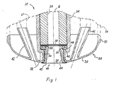
- the protective tip 40 is shown in Fig 1 with the cap 28 attached in place on a burner nozzle assembly, such as that of U.S. Patent 4,705,535, which is depicted in phantom.
- the burner nozzle assembly generally indicated by the numeral 10, has a central passageway 12 for an oxygen-containing gas, an annular passageway for a liquid (not shown), such as a slurry of comminuted carbonaceous particles in a carrier liquid, such as water, and a frustoconical passageway (not shown) ending in frustoconical surface, which carries additional oxygen-containing gas.
- Burner shell 26 also encompasses auxiliary fuel gas conduits 27 which are used for start-up preheat and for maintaining temperatures during periods when slurry is not being fed to the reactor. Also not shown because it is not relevant to the present invention, but available in the above-mentioned U.S. Patent, is the structure for the upstream end of the burner assembly 10.
- the cap 28 is a part of the protective and cooling tip 40 which prevents thermal and mechanical damage to burner assembly 10.
- At its upstream end is right cylindrical section 30 which attaches to the burner shell 26, for example by welding, and merges in a smooth curve to a rounded or an elliptical surface 32 at the downstream end.
- Cap 28 has a central circular discharge orifice 34, which is in axial alignment with the longitudinal central axis of burner nozzle assembly 10 and which is bounded by exit tube 36.
- Exit tube 36 over fits or attaches to the frustoconical conduit of burner nozzle assembly 10 in leak resistant fashion. This is particularly important because usually the gas-liquid system of this two-fluid burner nozzle is under pressures from atmospheric to 3500 psig (24,000 kPa gauge).
- Exit tube 36 has shoulder 38 which supports the heat shield or protective tip, generally indicated at 40.
- Auxiliary gas conduits 42 are provided to connect with auxiliary fuel gas conduits 27.
- Heat shield 40 has liner 44 which at its upstream end is a right cylinder and, progressing downstream, begins to diverge or flare outwardly from the central longitudinal axis of burner nozzle assembly 10.
- Liner 44 has a sharp corner 45 which causes the discharged atomized spray to continue the defined divergent pattern and form a conical spray in the combustion zone. This reduces eddy currents which circle back to the burner, causing flame damage to the cap 28.
- the liner 44 generally flares at an angle of from 5 to 10° from the longitudinal axis, preferably at about an 8° angle and, considering the entire circumference of the inside of liner 44, would be a 16° angle divergence.
- the heat shield preferably should not curve and thin to a great extent, but should maintain straight line divergence so that the flame front is directed out into the combustion zone and not dispersed too much at the nozzle tip 40. If so, eddy currents are more predominant and the oxygen surrounding the fuel mixture tends to react with the gaseous mixture in the combustion zone, such as synthesis gas, and burn immediately adjacent the burner tip, causing hot spots and thermal stress.
- a retaining ring 46 which is an annular structure, similar to a toroidal ring, having interior threads and a chamfered edge 48 which faces shoulder 38.
- Retaining ring 46 has on its rear surface two spanner holes 50 partially drilled through the retaining ring 46 and located about 180° apart. These are used with a spanner having corresponding lugs for installing the retaining ring on the liner 44.
- a hole 52 is drilled in the rear of the retaining ring 46 on an axis parallel to the longitudinal axis of the burner assembly 10 and in alignment with the threaded joint of the liner 44 and retaining ring 46, such that a locking pin (not shown) placed in the hole 52 prevents the liner 44 and retaining ring 46 from unscrewing and disengaging.
- packing material 54 is selected from graphite, metal gauze, tape packing and the like.
- An especially preferred form of graphite is a tape graphite packing, with a corrugated, flexible graphite ribbon material being especially preferred.
- Liner 44 and retaining ring 46 are preferably composed of heat resistant metal alloys.
- Typical metal alloys which retain their strength at high temperatures are nickel-chromium-steel alloys. Such alloys have greater strength at temperatures close to their melting points, i.e., from 2400 to 2500°F (1300 to 1370°C).
- Particularly preferred are Inconel alloys Incoloy 800H, Incoloy 800HT, Type 310 stainless steel, or Incoloy MA 956 (Incoloy is a trademark of INCO Alloys International, Inc., Huntington, West Virginia). Additionally, tungsten metal and tungsten alloys with the foregoing materials are useful. Other alloys having similar properties are likewise useful.
- an erosion resistant insert 56 which is employed particularly in the case of using a slurry of comminuted carbonaceous material as the liquid. Because the burner nozzle assembly 10 is set for a particular pressure, any erosion of the insert 56 will affect the shape of the discharge orifice and change the pressure and the atomization and dispersion of the gas-liquid mixture.
- an additional cooling feature of the present invention is provided by applying a cooled gas to the space between the liner 44 and cap 28.
- a cooled gas As shown in Figure 8, one means for accomplishing gas cooling directly behind liner 44 is provided by bore 60 which can be drilled through the shoulder 38 to a position in conduit 36 downstream of retaining ring 46.
- a slightly built-up area 62 is provided for attachment of a cooling media supply conduit 64 by any suitable means.
- the cooling media provided can be any inert or product gas of the system, such as, nitrogen, carbon dioxide, or synthesis gas produced in the gasification reactor.
Abstract
A two-piece, thermally resistant metal alloy heat shield (40) is provided for the central discharge orifice (34) of a two-fluid nozzle (10) for atomizing a liquid with a gas. The nozzle has at least a central conduit (12) and annular conduit (not shown) converging in an internal mixing zone for the liquid and gas and a central discharge orifice (34) having a shoulder (38) at its upstream end. The heat shield includes a retaining ring (46) and an outwardly flaring liner (44) for the orifice (34). The liner (44) is attached to the retaining ring (46) which bears against the shoulder (38) and is held in place by the flared construction at its downstream end. Preferably, the liner (44) has heat conductive flexible packing (54) disposed between its outside surface and the orifice (34). The orifice (34) may open into a protective cap (28) which is cylindrical at one end (30) and rounds out to an elliptical end surface (32).
Description
- This invention relates to a two-fluid nozzle for atomizing a liquid with a gas which includes a protector for the nozzle tip. In many applications, such as boilers, furnaces and coal gasification reactors, the harsh combustion environment unduly shortens nozzle life. The tip of the burner nozzle is most especially subjected to the greatest thermal stress. Thermal stress is defined as the mechanical force caused by expansion because of an increase in temperature of a body or portion thereof. Thermal stress can be very large especially at areas of high thermal gradient, for example, at the discharge outlet where the atomized fluids exit the nozzle into the furnace or combustion zone and the geometry of the nozzle changes from contacting internal temperatures to contacting combustion zone temperatures over a very short physical distance. Chemical reactions in the combustion zone, i.e., formation of, for example, soot, slag also greatly affect the tip. Mechanical erosion, for example by slurries, also presents nozzle throat and tip problems. Some industries accept this as a fact of life and plan for frequent nozzle changes. Others, in order to extend nozzle life have fabricated inserts of materials which are more resistant to the stresses encountered for parts that are subjected to the most stress. For example, Schlinger, U.S. 4,443,228, has added inserts of refractory material, such as tungsten carbide or silicon carbide to decrease mechanical erosion at the nozzle tip caused by slurries. Unfortunately, such materials are expensive, difficult to fashion into complex shapes and can nevertheless fail.
- The present invention seeks to provide a nozzle which is highly efficient in atomizing the gas-liquid mixture, and which is more stable and durable to the various stresses of the harsh environment of use without changing the burner configuration greatly, or increasing the difficulty of manufacture by working with exotic ceramic or refractory materials.
- The present invention provides a burner nozzle assembly tip connected to the downstream end of a burner nozzle assembly, in which said burner nozzle assembly has at least two conduits for atomization of a liquid selected from liquid carbonaceous materials and a slurry of carbonaceous material with an oxidizing gas, said two conduits including at least a central and annular conduit containing said liquid and said gas, respectively, and which converge at an internal mixing zone to provide efficient mixing for the liquid fuel and oxidizing gas for discharge through a discharge orifice and to a combustion zone for combustion at a relatively high temperature, said tip comprising a central outlet having a shoulder at its upstream end and a thermally resistant metal alloy heat shield attached to a retaining ring which is located upstream of said shoulder and in contact therewith and said heat shield comprising a cylindrical liner having an upstream end and a downstream end, the upstream end of which has a diameter less than said outlet, said liner diverging outwardly from the central longitudinal axis of said burner nozzle assembly to a diameter larger than said outlet at its downstream end, whereby said outlet is partially covered by said liner and protects said outlet from the heat produced by the combustion temperature. The burner nozzle assembly tip is preferably of a heat resistant metal alloy, such as a nickel-chromium-steel alloy and, more preferably, for example, Inconel alloys such as Incoloy 800H, Incoloy 800HT, Type 310 Stainless steel, or Incoloy MA956 (Incoloy is a trademark of INCO Alloys International, Inc.). Further, the space between the nozzle and the liner of the nozzle can be packed with a compressible, heat- insulating material, such as, graphite, metal gauze, or tape packing. A preferred nozzle tip of this invention includes a two-piece heat shield in which the liner and retaining ring are threadedly connected and, more preferably, being unitized by a locking pin to prevent the parts from unscrewing and disengaging.
- The attached drawings, which are included in this specification and form a part hereof, illustrate a specific, non-limiting embodiment of the invention. In each of the Figures of the Drawings, like numerals represent like parts and
- Figure 1 is a sectional view of part of a two-fluid burner nozzle assembly tip having the heat shield of this invention in place and showing in phantom the downstream end of the burner nozzle assembly;
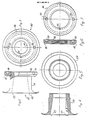
- Figure 2 is a partial sectional side view of the assembled liner and retaining ring in operating position relative to each other;
- Figure 3 is a rear view of the assembled liner and retaining ring shown in Fig. 2;
- Figure 4 is a sectional side view of the liner;
- Figure 5 is a rear view of the liner;
- Figure 6 is a sectional side view of the retaining ring;
- Figure 7 is a rear view of the retaining ring; and
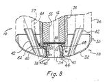
- Figure 8 is a sectional view of an alternative embodiment of a two-fluid burner nozzle assembly tip, having the heat shield additionally cooled by a gas stream.
- The burner nozzle of this invention can be useful in any application requiring the use of a burner nozzle which is subject to the thermal, mechanical and chemical stresses of harsh environments, such as furnaces or coal gasification reactors in atomizing a two-fluid system, such as oxygen, air or oxygen-containing gas and liquid hydrocarbonaceous or solid carbonaceous slurried fuels. Although many other applications are known for the burner nozzle of this invention, the most severe environment appears to be that found in an entrained, slagging coal gasification reactor. Typical of such reactors are upflow systems. For purposes of illustration, a typical heat shield arrangement for such an environment will be more particularly described.
- As described in coassigned U.S. 4,705,535, to Lipp, issued November 10, 1987, a two-fluid nozzle which is adjustable to provide a substantially constant mixing energy is disclosed. For the purposes of that invention, the nozzle is more specifically defined and includes a microprocessor to calculate the mixing energy from the pressure and mass flow values of the liquid and gas fed to the nozzle as measured by the appropriate sensing devices.
- The problem solved by the present invention is to prevent the burner face from failing by cracking because of thermal stress from the heat produced in the furnace or gasification reactor. This is accomplished by the protective tip or heat shield structure and the materials employed in the structure provided. The invention provides a tip for a burner nozzle such as that described in U.S. 4,705,535 and a shield or protecting tip which prevents direct contact and heat conduction for the burner assembly from the two-fluid mixture and its combustion products during combustion.
- As presently contemplated, the protecting tip is coaxial with the central longitudinal axis of the burner assembly and provides an unobstructed central conduit from the discharge orifice of the burner assembly to the reactor or furnace combustion zone. Generally, the protecting tip includes a cap portion and a heat shield portion. Because the nozzle cap and heat shield are attachable to the downstream end of the burner assembly a number of burners can be used with appropriate adaptation to the cap portion. Particularly, the cap portion must adapt to the cooling jacket of the burner nozzle assembly and, as shown in Figures 1 and 8, provide for fuel gas conduits to be used in preheat and heat maintenance conditions. Thus, prior art burners in addition to those described in U.S. 4,705,535, are useful without a great deal of adaptation required in the burner nozzle assembly. Therefore, the present invention is not limited to the described and incorporated reference burner of U.S. 4,705,535.
- The coaxial shield conduit is encompassed and defined by a cylindrical tube or liner having an upstream end and a downstream end. The upstream end is adjacent to the burner discharge orifice while the downstream end opens to the reactor or furnace combustion zone. The liner or tube is preferably cylindrical in shape at the upstream end and diverges outwardly from the central longitudinal axis at its down stream end. Preferably, the heat shield liner ends abruptly in a sharp corner instead of continuing to flare outwardly in a smooth curve. This is to prevent the undue mixing of the highly atomized mixture of gas and liquid with hot recirculating reactor gas to prevent combustion adjacent the nozzle tip.
- The length of the tube or liner is determined by the height of the cap portion and the size of the liner is determined by the amount of material required to flow through the liner. The degree of flare should be sufficient to cover the relatively sharp transition of the cap and burner nozzle from a central conduit axially aligned with the longitudinal axis of the burner assembly to an angle of 90° or more to the flat or rounded convex curve of the burner or cap face. It is at these sharp transitions that thermal and mechanical stresses occur with greater intensity. The highly localized stresses produced are more likely to cause failures in the burner or cap because of the intensified stresses. The liner may be composed of a thermally resistant metal alloy, a number of which are known. Typical of such thermally resistant alloys are nickel-chromium-steel alloys such as, Inconel alloys Incoloy 800HT, Incoloy MA956, Incoloy 800H, and Type 310 Stainless Steel nickel chromium steel, to name a few major types (Incoloy is a trademark of INCO Alloys International, Inc., Huntington, West Virginia).
- The liner is held in place by a retaining ring which is connected to the liner by any conventional means, such as a threaded connection. When a threaded connection is used, the liner and retaining ring are held together and prevented from unscrewing by drilling a small hole from the rear of the retaining ring into the intersecting thread and inserting a locking pin, as is conventional and known in the fastener industry for unitizing threaded connections. The retaining ring has an outside diameter larger than the liner and bears on a shoulder upstream of the liner at the point where the liner and retaining ring join. The larger retaining ring thus prevents the shield from being blown into the furnace or gasifier with the two-fluid mixture.
- The cap is a smoothly rounded or elliptical surface attached to the burner assembly face to provide for the water jacket and to allow the burner internals to be easily fabricated, assembled and then covered so that these are not exposed to the combustion zone environment. The cap has matching conduits for each of the discharge orifices of the burner. Any method of attachment to the burner face can be employed, but it is preferred to weld the cap to the burner assembly.
- As more specifically illustrated in the drawings, the
protective tip 40 is shown in Fig 1 with thecap 28 attached in place on a burner nozzle assembly, such as that of U.S. Patent 4,705,535, which is depicted in phantom. The burner nozzle assembly, generally indicated by thenumeral 10, has acentral passageway 12 for an oxygen-containing gas, an annular passageway for a liquid (not shown), such as a slurry of comminuted carbonaceous particles in a carrier liquid, such as water, and a frustoconical passageway (not shown) ending in frustoconical surface, which carries additional oxygen-containing gas. These passageways are bounded, respectively, by central conduit, annular conduit, and frustoconical conduit, all as shown in U.S. Patent 4,705,535. These conduits are carried incylindrical burner shell 26. Appropriate spacers, vanes, fins and spiders (not indicated) are used to maintain concentricity of the various conduits and provide as little restriction to fluid flow as possible. Also, theburner shell 26 can carry cooling liquid, such as water, to cool the burner assembly; however, for the sake of simplicity the connections for these, shown in the prior art, are not indicated.Burner shell 26 also encompasses auxiliaryfuel gas conduits 27 which are used for start-up preheat and for maintaining temperatures during periods when slurry is not being fed to the reactor. Also not shown because it is not relevant to the present invention, but available in the above-mentioned U.S. Patent, is the structure for the upstream end of theburner assembly 10. - The
cap 28 is a part of the protective and coolingtip 40 which prevents thermal and mechanical damage toburner assembly 10. At its upstream end is rightcylindrical section 30 which attaches to theburner shell 26, for example by welding, and merges in a smooth curve to a rounded or anelliptical surface 32 at the downstream end.Cap 28 has a centralcircular discharge orifice 34, which is in axial alignment with the longitudinal central axis ofburner nozzle assembly 10 and which is bounded byexit tube 36.Exit tube 36 over fits or attaches to the frustoconical conduit ofburner nozzle assembly 10 in leak resistant fashion. This is particularly important because usually the gas-liquid system of this two-fluid burner nozzle is under pressures from atmospheric to 3500 psig (24,000 kPa gauge). If the attachment were not leak resistant, slurry would be lost to theburner shell 26 and taken out with the cooling water, resulting in waste problems, decreased economics, and operating problems.Exit tube 36 hasshoulder 38 which supports the heat shield or protective tip, generally indicated at 40.Auxiliary gas conduits 42 are provided to connect with auxiliaryfuel gas conduits 27. -
Heat shield 40 hasliner 44 which at its upstream end is a right cylinder and, progressing downstream, begins to diverge or flare outwardly from the central longitudinal axis ofburner nozzle assembly 10.Liner 44 has asharp corner 45 which causes the discharged atomized spray to continue the defined divergent pattern and form a conical spray in the combustion zone. This reduces eddy currents which circle back to the burner, causing flame damage to thecap 28. Theliner 44 generally flares at an angle of from 5 to 10° from the longitudinal axis, preferably at about an 8° angle and, considering the entire circumference of the inside ofliner 44, would be a 16° angle divergence. However, it has been found that the heat shield preferably should not curve and thin to a great extent, but should maintain straight line divergence so that the flame front is directed out into the combustion zone and not dispersed too much at thenozzle tip 40. If so, eddy currents are more predominant and the oxygen surrounding the fuel mixture tends to react with the gaseous mixture in the combustion zone, such as synthesis gas, and burn immediately adjacent the burner tip, causing hot spots and thermal stress. - As more easily seen in Figures 2-7, the
liner 44 is held in place by a retainingring 46 which is an annular structure, similar to a toroidal ring, having interior threads and achamfered edge 48 which facesshoulder 38. Retainingring 46 has on its rear surface twospanner holes 50 partially drilled through the retainingring 46 and located about 180° apart. These are used with a spanner having corresponding lugs for installing the retaining ring on theliner 44. When the retainingring 46 is installed on the cap 28 ahole 52 is drilled in the rear of the retainingring 46 on an axis parallel to the longitudinal axis of theburner assembly 10 and in alignment with the threaded joint of theliner 44 and retainingring 46, such that a locking pin (not shown) placed in thehole 52 prevents theliner 44 and retainingring 46 from unscrewing and disengaging. - About the outside of the
liner 44, there is disposed a compressible andconductive packing material 54 to aid in taking heat away from theliner 44. While the packingmaterial 54 should be heat conductive, it should not conduct heat away too rapidly and create a large temperature difference between the inside and outside surfaces ofliner 44, creating large thermal stresses in the process.Packing material 54 should also be compressible so that thermal expansion ofliner 44 can be accommodated. Typically, packingmaterial 54 is selected from graphite, metal gauze, tape packing and the like. An especially preferred form of graphite is a tape graphite packing, with a corrugated, flexible graphite ribbon material being especially preferred. -
Liner 44 and retainingring 46 are preferably composed of heat resistant metal alloys. Typical metal alloys which retain their strength at high temperatures are nickel-chromium-steel alloys. Such alloys have greater strength at temperatures close to their melting points, i.e., from 2400 to 2500°F (1300 to 1370°C). Particularly preferred are Inconel alloys Incoloy 800H, Incoloy 800HT, Type 310 stainless steel, or Incoloy MA 956 (Incoloy is a trademark of INCO Alloys International, Inc., Huntington, West Virginia). Additionally, tungsten metal and tungsten alloys with the foregoing materials are useful. Other alloys having similar properties are likewise useful. - Located within
conduit 36 of thecap 28 can, optionally, be an erosionresistant insert 56 which is employed particularly in the case of using a slurry of comminuted carbonaceous material as the liquid. Because theburner nozzle assembly 10 is set for a particular pressure, any erosion of theinsert 56 will affect the shape of the discharge orifice and change the pressure and the atomization and dispersion of the gas-liquid mixture. The use of refractory or ceramic inserts, known in the art, but not in the manner of the present invention, such as, for example, tungsten carbide, silicon carbide, aluminum nitride, and boron carbide, decreases the likelihood of erosion.Insert 56 is supported by gasket orwasher 58. - Optionally, an additional cooling feature of the present invention is provided by applying a cooled gas to the space between the
liner 44 andcap 28. As shown in Figure 8, one means for accomplishing gas cooling directly behindliner 44 is provided bybore 60 which can be drilled through theshoulder 38 to a position inconduit 36 downstream of retainingring 46. A slightly built-uparea 62 is provided for attachment of a coolingmedia supply conduit 64 by any suitable means. The cooling media provided can be any inert or product gas of the system, such as, nitrogen, carbon dioxide, or synthesis gas produced in the gasification reactor.
Claims (14)
1. A burner nozzle assembly tip for a burner nozzle assembly having at least two conduits for atomization of a liquid selected from liquid carbonaceous materials and a slurry of carbonaceous material with an oxidizing gas, said two conduits including at least a central and annular conduit containing said liquid and said gas, respectively and which converge at an internal mixing zone to provide efficient mixing for the liquid fuel and oxidizing gas for discharge through a discharge orifice and to a combustion zone for combustion at a relatively high temperature, said tip comprising a central outlet having a shoulder at its upstream end and a thermally resistant metal alloy heat shield attached to a retaining ring which is located upstream of said shoulder and in contact therewith, said heat shield comprising a cylindrical liner having an upstream end and a downstream end, the upstream end of which has a diameter less than said outlet, said liner diverging outwardly from the central longitudinal axis of said burner nozzle assembly to a diameter larger than said outlet at its downstream end, whereby said outlet is partially covered by said liner and protects said outlet from the heat produced by the combustion temperature.
2. A burner nozzle assembly tip as claimed in Claim 1 having a compressible thermally insulating material between said outlet and said liner.
3. A burner nozzle assembly tip as claimed in Claim 2 in which said thermally insulating material is selected from graphite, metal gauge and tape packing
4. A burner nozzle assembly tip as claimed in Claim 3 in which said graphite is a graphite ribbon.
5. A burner nozzle assembly tip as claimed in any one of the preceding claims in which said liner and said retaining ring are threadedly connected.
6. A burner nozzle assembly tip as claimed in Claim 5 in which said liner and said retaining ring are unitized by insertion of a locking pin in a hole drilled in the threaded connection, binding said liner and said retaining ring together and preventing relative rotation and unscrewing thereof.
7. A burner nozzle assembly tip as claimed in any one of the preceding claims in which said retaining ring and liner are composed of a heat resistant alloy.
8. A burner nozzle assembly tip as claimed in Claim 7 in which said heat resistant alloy is a nickel-chromium-steel alloy.
9. A burner nozzle assembly tip as claimed in any one of the preceding claims, wherein said burner nozzle assembly is covered by a cap having a right cylindrical section including an upstream end and a downstream end, said upstream end being capable of attachment to a burner nozzle assembly at the downstream end thereof and converging on a smooth curve to a convex rounded surface culminating in said outlet.
10. A burner nozzle assembly tip as claimed in any one of the preceding claims, wherein said liner terminates abruptly in a sharp corner at its downstream end.
11. A burner nozzle assembly tip as claimed in any one of the preceding claims, wherein said liner diverges at an angle of 5 to 10° from said longitudinal axis.
12. A burner nozzle assembly tip as claimed in any one of the preceding claims, wherein said liner diverges in a straight line.
13. A burner nozzle assembly tip as claimed in any one of the preceding claims, wherein means are provided for introducing a cooling gas between said liner and said outlet.
14. A heat shield assembly for a burner nozzle assembly tip as claimed in Claim 1, wherein said heat shield assembly comprises a liner and retaining ring as defined in any one of Claims 1, 5, 7 and 9.
Applications Claiming Priority (2)
| Application Number | Priority Date | Filing Date | Title |
|---|---|---|---|
| US238217 | 1988-08-26 | ||
| US07/238,217 US4952218A (en) | 1988-08-26 | 1988-08-26 | Two-fluid nozzle for atomizing a liquid solid slurry and protecting nozzle tip |
Publications (1)
| Publication Number | Publication Date |
|---|---|
| EP0362997A1 true EP0362997A1 (en) | 1990-04-11 |
Family
ID=22896966
Family Applications (1)
| Application Number | Title | Priority Date | Filing Date |
|---|---|---|---|
| EP89308442A Withdrawn EP0362997A1 (en) | 1988-08-26 | 1989-08-21 | Burner nozzle assembly tip |
Country Status (9)
| Country | Link |
|---|---|
| US (1) | US4952218A (en) |
| EP (1) | EP0362997A1 (en) |
| JP (1) | JPH02126013A (en) |
| KR (1) | KR900002848A (en) |
| CN (1) | CN1040861A (en) |
| AU (1) | AU4028889A (en) |
| CA (1) | CA1316095C (en) |
| DK (1) | DK417989A (en) |
| ZA (1) | ZA896514B (en) |
Cited By (3)
| Publication number | Priority date | Publication date | Assignee | Title |
|---|---|---|---|---|
| EP0919769A1 (en) * | 1997-12-01 | 1999-06-02 | L'air Liquide, Societe Anonyme Pour L'etude Et L'exploitation Des Procedes Georges Claude | Device for protecting the injection tip of a burner and heating device comprising it |
| WO2001081825A1 (en) * | 2000-04-21 | 2001-11-01 | Eastman Chemical Company | Threaded heat shield for burner nozzle face |
| EP2282115A1 (en) * | 2009-07-30 | 2011-02-09 | Alstom Technology Ltd | Burner of a gas turbine |
Families Citing this family (26)
| Publication number | Priority date | Publication date | Assignee | Title |
|---|---|---|---|---|
| DE4140063A1 (en) * | 1991-12-05 | 1993-06-09 | Hoechst Ag, 6230 Frankfurt, De | BURNER FOR THE PRODUCTION OF SYNTHESIS GAS |
| US5261602A (en) * | 1991-12-23 | 1993-11-16 | Texaco Inc. | Partial oxidation process and burner with porous tip |
| US5575423A (en) * | 1994-09-30 | 1996-11-19 | Rockwell International Corporation | Tube nozzle having thermal transient reduction |
| US5904477A (en) * | 1995-10-05 | 1999-05-18 | Shell Oil Company | Burner for partial oxidation of a hydrocarbon-containing fuel |
| US5785721A (en) * | 1997-01-31 | 1998-07-28 | Texaco Inc. | Fuel injector nozzle with preheat sheath for reducing thermal shock damage |
| US5934206A (en) * | 1997-04-07 | 1999-08-10 | Eastman Chemical Company | High temperature material face segments for burner nozzle secured by brazing |
| WO2001056703A1 (en) * | 2000-02-03 | 2001-08-09 | Corning Incorporated | Refractory burner nozzle with stress relief slits |
| US6284324B1 (en) * | 2000-04-21 | 2001-09-04 | Eastman Chemical Company | Coal gasification burner shield coating |
| US6755355B2 (en) * | 2002-04-18 | 2004-06-29 | Eastman Chemical Company | Coal gasification feed injector shield with integral corrosion barrier |
| US8231068B2 (en) * | 2004-06-16 | 2012-07-31 | Pratt & Whitney Rocketdyne, Inc. | Dry, low nitrous oxide calciner injector |
| US7993131B2 (en) * | 2007-08-28 | 2011-08-09 | Conocophillips Company | Burner nozzle |
| DE102008020204B4 (en) * | 2008-04-22 | 2011-12-01 | Choren Industries Gmbh | Burner holding device with cooling system for a burner arrangement in an entrained flow gasifier |
| CN101738326B (en) * | 2008-11-11 | 2012-03-28 | 北京航空航天大学 | Gas-gas single-nozzle experimental device |
| US9120985B2 (en) | 2010-05-26 | 2015-09-01 | Exxonmobil Research And Engineering Company | Corrosion resistant gasifier components |
| US9079199B2 (en) * | 2010-06-14 | 2015-07-14 | General Electric Company | System for increasing the life of fuel injectors |
| US8336791B1 (en) | 2010-09-07 | 2012-12-25 | J.M. Parish Enterprises, LLC | Insert assembly for a nozzle |
| US20120317992A1 (en) * | 2011-06-17 | 2012-12-20 | General Electric Company | Feed injector for gasification system |
| WO2014024942A1 (en) * | 2012-08-07 | 2014-02-13 | 日野自動車 株式会社 | Burner |
| CN104136845B (en) * | 2012-08-07 | 2015-09-23 | 日野自动车株式会社 | Emission-control equipment burner |
| EP2843306A4 (en) | 2012-08-07 | 2015-12-02 | Hino Motors Ltd | Burner for exhaust gas purification devices |
| CN104603539B (en) * | 2012-08-13 | 2017-06-23 | 日野自动车株式会社 | Burner |
| US20150059322A1 (en) * | 2013-08-30 | 2015-03-05 | Continental Automotive Systems, Inc. | Liquid cooled reductant delivery unit for automotive selective catalytic reduction systems |
| JP6317631B2 (en) * | 2014-06-12 | 2018-04-25 | 三菱日立パワーシステムズ株式会社 | Spray nozzle, combustion apparatus equipped with spray nozzle, and gas turbine plant |
| CN106556011A (en) * | 2015-09-24 | 2017-04-05 | 潞安卓泰祥和金属科技宜兴有限公司 | A kind of new oxygen-enriched burner |
| EP3615699A4 (en) | 2017-04-26 | 2021-01-13 | Linde GmbH | Method and burner for heating a furnace for metal processing |
| CN109022044B (en) * | 2018-10-19 | 2023-10-20 | 四川蓝星机械有限公司 | Coal gasification reaction device |
Citations (3)
| Publication number | Priority date | Publication date | Assignee | Title |
|---|---|---|---|---|
| FR2283859A1 (en) * | 1974-09-09 | 1976-04-02 | Shell Int Research | METHOD AND APPARATUS FOR THE CARBONATION OF OILS |
| US4352675A (en) * | 1979-11-30 | 1982-10-05 | Ruhrkohle Aktiengesellschaft | Coal gasification reactor |
| US4364744A (en) * | 1979-12-26 | 1982-12-21 | Texaco Inc. | Burner for the partial oxidation of slurries of solid carbonaceous fuels |
Family Cites Families (11)
| Publication number | Priority date | Publication date | Assignee | Title |
|---|---|---|---|---|
| US2806522A (en) * | 1953-04-03 | 1957-09-17 | Owens Corning Fiberglass Corp | Combustion burner and nozzle construction |
| US3101906A (en) * | 1962-01-11 | 1963-08-27 | Carl R Webber | Spray nozzle |
| US3129777A (en) * | 1962-08-07 | 1964-04-21 | Hughes Tool Co | Replaceable nozzle having completely shrouded retainer |
| US3698646A (en) * | 1971-01-08 | 1972-10-17 | Pfizer | Composite carbon insert for gas shielded welding torch nozzle |
| US4221336A (en) * | 1978-10-31 | 1980-09-09 | Diamond Harvey E | Nozzle with directionally variable outlet |
| DE3000061C2 (en) * | 1980-01-03 | 1993-10-14 | Bosch Gmbh Robert | Fuel injection nozzle for internal combustion engines |
| US4443228A (en) * | 1982-06-29 | 1984-04-17 | Texaco Inc. | Partial oxidation burner |
| EP0113342B1 (en) * | 1982-07-12 | 1988-09-14 | Combustion Engineering, Inc. | Nozzle tip for pulverized coal burner |
| US4443230A (en) * | 1983-05-31 | 1984-04-17 | Texaco Inc. | Partial oxidation process for slurries of solid fuel |
| US4705535A (en) * | 1986-03-13 | 1987-11-10 | The Dow Chemical Company | Nozzle for achieving constant mixing energy |
| US4785996A (en) * | 1987-04-23 | 1988-11-22 | Nordson Corporation | Adhesive spray gun and nozzle attachment |
-
1988
- 1988-08-26 US US07/238,217 patent/US4952218A/en not_active Expired - Lifetime
-
1989
- 1989-08-21 EP EP89308442A patent/EP0362997A1/en not_active Withdrawn
- 1989-08-24 DK DK417989A patent/DK417989A/en not_active Application Discontinuation
- 1989-08-25 JP JP1220165A patent/JPH02126013A/en active Pending
- 1989-08-25 CA CA000609406A patent/CA1316095C/en not_active Expired - Lifetime
- 1989-08-25 ZA ZA896514A patent/ZA896514B/en unknown
- 1989-08-25 AU AU40288/89A patent/AU4028889A/en not_active Abandoned
- 1989-08-25 KR KR1019890012137A patent/KR900002848A/en not_active Application Discontinuation
- 1989-08-26 CN CN89106661A patent/CN1040861A/en active Pending
Patent Citations (3)
| Publication number | Priority date | Publication date | Assignee | Title |
|---|---|---|---|---|
| FR2283859A1 (en) * | 1974-09-09 | 1976-04-02 | Shell Int Research | METHOD AND APPARATUS FOR THE CARBONATION OF OILS |
| US4352675A (en) * | 1979-11-30 | 1982-10-05 | Ruhrkohle Aktiengesellschaft | Coal gasification reactor |
| US4364744A (en) * | 1979-12-26 | 1982-12-21 | Texaco Inc. | Burner for the partial oxidation of slurries of solid carbonaceous fuels |
Cited By (8)
| Publication number | Priority date | Publication date | Assignee | Title |
|---|---|---|---|---|
| EP0919769A1 (en) * | 1997-12-01 | 1999-06-02 | L'air Liquide, Societe Anonyme Pour L'etude Et L'exploitation Des Procedes Georges Claude | Device for protecting the injection tip of a burner and heating device comprising it |
| WO1999028676A1 (en) * | 1997-12-01 | 1999-06-10 | Sociedade Portuguesa Do Ar Liquido 'arliquido', Lda | Device for protecting the injection tip of a burner and heating device comprising it |
| US6089858A (en) * | 1997-12-01 | 2000-07-18 | L'air Liquide, Societe Anonyme Pour L'etude De L'exploitation Des Procedes Georges Claude | Device for protecting the injection tip of a burner and heating device comprising it |
| WO2001081825A1 (en) * | 2000-04-21 | 2001-11-01 | Eastman Chemical Company | Threaded heat shield for burner nozzle face |
| US6358041B1 (en) | 2000-04-21 | 2002-03-19 | Eastman Chemical Company | Threaded heat shield for burner nozzle face |
| EP2282115A1 (en) * | 2009-07-30 | 2011-02-09 | Alstom Technology Ltd | Burner of a gas turbine |
| EP2284441A3 (en) * | 2009-07-30 | 2014-12-17 | Alstom Technology Ltd | Burner of a gas turbine |
| US9435532B2 (en) | 2009-07-30 | 2016-09-06 | General Electric Technology Gmbh | Burner of a gas turbine |
Also Published As
| Publication number | Publication date |
|---|---|
| CN1040861A (en) | 1990-03-28 |
| CA1316095C (en) | 1993-04-13 |
| ZA896514B (en) | 1991-04-24 |
| JPH02126013A (en) | 1990-05-15 |
| DK417989D0 (en) | 1989-08-24 |
| KR900002848A (en) | 1990-03-23 |
| AU4028889A (en) | 1990-03-01 |
| DK417989A (en) | 1990-02-27 |
| US4952218A (en) | 1990-08-28 |
Similar Documents
| Publication | Publication Date | Title |
|---|---|---|
| US4952218A (en) | Two-fluid nozzle for atomizing a liquid solid slurry and protecting nozzle tip | |
| US4887962A (en) | Partial combustion burner with spiral-flow cooled face | |
| CA1295192C (en) | Partial combustion burner | |
| US5449286A (en) | Controlled flame fuel jet combustion | |
| KR101535474B1 (en) | Burner | |
| EP0805937B1 (en) | Improved partial oxidation process burner with recessed tip and gas blasting | |
| CA2239566C (en) | A process for preparing synthesis gas | |
| US4865542A (en) | Partial combustion burner with spiral-flow cooled face | |
| CN201228965Y (en) | Combustor | |
| US4458607A (en) | Process and burner for the partial combustion of finely divided solid fuel | |
| EP0328794B1 (en) | Partial combustion burner with spiral-flow cooled face | |
| US6152052A (en) | High temperature material face segments for burner nozzle secured by brazing | |
| CA1210248A (en) | Method and apparatus for injecting pulverized fuel into a blast furnace | |
| JPS61138016A (en) | Burner | |
| US5947716A (en) | Breech lock heat shield face for burner nozzle | |
| JP2004510938A (en) | Threaded heat shield for burner nozzle surface | |
| US4775314A (en) | Coal gasification burner | |
| CA1308644C (en) | Ceramic burner for partial oxidation of a hydrocarbon-containing fuel | |
| KR100204159B1 (en) | Blast pipe and tuyere apparatus | |
| US5588974A (en) | Process, and apparatus, for the injection of preheated oxygen into a high temperature reactor | |
| US5904477A (en) | Burner for partial oxidation of a hydrocarbon-containing fuel | |
| CN201218499Y (en) | Burner | |
| US3669628A (en) | Burner and feedstock injection assembly for carbon black reactor | |
| JP2527922B2 (en) | Pulverized coal oxygen combustion burner | |
| EP0108425A1 (en) | Burner for the partial combustion of finely divided solid fuel |
Legal Events
| Date | Code | Title | Description |
|---|---|---|---|
| PUAI | Public reference made under article 153(3) epc to a published international application that has entered the european phase |
Free format text: ORIGINAL CODE: 0009012 |
|
| AK | Designated contracting states |
Kind code of ref document: A1 Designated state(s): BE CH DE ES FR GB GR IT LI NL SE |
|
| 17P | Request for examination filed |
Effective date: 19901005 |
|
| 17Q | First examination report despatched |
Effective date: 19910508 |
|
| STAA | Information on the status of an ep patent application or granted ep patent |
Free format text: STATUS: THE APPLICATION IS DEEMED TO BE WITHDRAWN |
|
| 18D | Application deemed to be withdrawn |
Effective date: 19911228 |