EP0361046A2 - Constrained uniform field gel electrophoresis - Google Patents
Constrained uniform field gel electrophoresis Download PDFInfo
- Publication number
- EP0361046A2 EP0361046A2 EP89114817A EP89114817A EP0361046A2 EP 0361046 A2 EP0361046 A2 EP 0361046A2 EP 89114817 A EP89114817 A EP 89114817A EP 89114817 A EP89114817 A EP 89114817A EP 0361046 A2 EP0361046 A2 EP 0361046A2
- Authority
- EP
- European Patent Office
- Prior art keywords
- gel
- box
- electric field
- baffle
- gel box
- Prior art date
- Legal status (The legal status is an assumption and is not a legal conclusion. Google has not performed a legal analysis and makes no representation as to the accuracy of the status listed.)
- Granted
Links
Images


Classifications
-
- G—PHYSICS
- G01—MEASURING; TESTING
- G01N—INVESTIGATING OR ANALYSING MATERIALS BY DETERMINING THEIR CHEMICAL OR PHYSICAL PROPERTIES
- G01N27/00—Investigating or analysing materials by the use of electric, electrochemical, or magnetic means
- G01N27/26—Investigating or analysing materials by the use of electric, electrochemical, or magnetic means by investigating electrochemical variables; by using electrolysis or electrophoresis
- G01N27/416—Systems
- G01N27/447—Systems using electrophoresis
- G01N27/44756—Apparatus specially adapted therefor
- G01N27/44773—Multi-stage electrophoresis, e.g. two-dimensional electrophoresis
Definitions
- This invention concerns apparatus for gel electrophoresis of high molecular weight DNA.
- Cantor et al. U.S. Patents 4,473,452 and 4,695,5408 describe a system in which generally non-uniform electric fields change direction in the plane of the gel. While the mechanism by which this electrophoresis method operates to move large DNA molecules is not entirely understood, Cantor et al. propose that the application of alternating fields causes a coiled DNA molecule to be squeezed into the gel matrix by orientating itself first along the general direction of one of the fields and then along the general direction of the other, and so on.
- This method of electrophoresis depends on a complex network of diodes and resistors to fix the electric potential at a number of points around the gel, and thus fix the electric field in the gel.
- This method can also be used for electrophoresis in non-uniform fields.
- Laas et al. U.S. Patent 4,740,283
- a 1987 Beckman Instrument advertisement entitled GENELINE TM describe a pulse field gradient gel electrophoresis apparatus having electrode arrays oriented to provide three dimensional fields across the face of the gel.
- Serwer U.S. Patent 4,693,804 describes an apparatus for conducting electrophoresis in two dimensions without need to move a gel after electrophoresis in a first dimension.
- Barriers are provided to limit an electric field to a rectanqular shape and prevent passage of electricity. After electrophoresis in a first dimension these barriers are removed and new barriers erected to form a new electric field in a rectangular shape oriented at 90° to the first.
- This invention features an electrophoresis apparatus and method which provide good resolution of high molecular weight DNA molecules at low cost.
- the electrophoresis chamber of the apparatus is shaped to constrain two transversely applied electric fields such that high-molecular weight DNA is resolved in straight gel lanes by uniform electric fields.
- This invention can be used at a high power rating with any thickness of gel and any conductivity of buffer that is normally used for gel electrophoresis, including gels useful for preparative and high sensitivity work. Buffers of high conductivity are especially preferred for resolution of high molecular weight DNA. Power consumption may also be maintained at a low enough level to require only inexpensive power supplies that are commonly used for DNA gel electrophoresis.
- the gel may be sized as required, the limitation being physical, rather than electrical.
- the invention features, in a first aspect, gel electrophoresis apparatus for separating DNA molecules of high molecular weight having means for generating first and second electric fields, the fields being oriented transversely to each other, and a gel box shaped and contoured to simultaneously form both the electric fields into generally uniform electric fields.
- uniform electric field is meant that the electric field strength (in volts/cm) generated in the gel box varies by less than 20% from an average value in the gel box, preferably less than 10% and even more preferably less than 5%, particularly in the area of the gel box in which a DNA sample is placed and electrophoresed.
- semiultaneously is meant that the gel box is shaped and contoured to form both of the electric fields into uniform electric fields without need for the gel box to be altered in its shape or contouring when the means is switched to generate either electric field.
- the means includes at least four electrodes positioned near the outer perimeter of the box which is defined by a wall forming the shape of the box.
- the outer perimeter is shaped to accept a gel and buffer, the perimeter having the shape of two rectangles placed on top of each other at an angle of between 90° and 135°, preferably the rectangles are identical in shape, and at least one corner of one rectangle coincides with a corner of the other rectangle, most preferably the rectangles coincide at two corners.
- the gel box includes at least one baffle means formed of electrically non-conducting material positioned and arranged to limit formation of a non-uniform electric field in the gel box.
- the baffle means is oriented along the overall direction of the first electric field, and is positioned and arranged to limit formation of a non-uniform field in the second electric field; most preferably, the baffle means is a set of baffle elements and the apparatus has a plurality of these baffle elements, with at least one baffle element, but preferably all baffle elements, oriented along the overall direction of the first or second electric field to prevent formation of a non-uniform electric field in the other electric field.
- the baffle means is preferably in contact with the outer perimeter and base of the gel box, and has a height equal to that of the gel box.
- each baffle element is in contact with the outer perimeter of the gel box and extends along the direction of the first or second uniform electric field to the edge of the other uniform electric field.
- Each electrode is generally separated from all other electrodes of the same polarity by a baffle formed of electrically non-conducting material, the baffle preventing direct electric conduction between these electrodes through a medium in the gel box.
- the apparatus is suitable for use in DNA sequencing, having two plates and a baffle means positioned to sandwich a polyacrylamide gel.
- the invention features a method for separating DNA molecules of high molecular weight, including the steps of positioning the DNA molecules within a gel matrix; providing means for generating alternating transversely applied uniform electric fields, and positioning the gel matrix in a gel box sized, shaped, and contoured to simultaneously form two generally transverse uniform electric fields, and subjecting the gel matrix to these alternating electric fields.
- An electrophoresis cell useful in this invention generally has an X-shape, and is termed an X-box. Two uniform electric fields which alternate at a 120° angle to each other are provided. Uniformity of fields is achieved by the shape of the electrophoresis cell of the invention.
- X-box 10 has a flat base 12 of an electrically non-conducting material, such as acrylic plastic.
- Vertical walls 14 in combination with ends 20, 22, 24 and 26 define an outer perimeter, and with the base define a volume for containing a gel 15 and buffer.
- Baffle elements 16, 17 extend, respectively, from ends 20, 26 and ends 22, 24.
- the baffle elements, walls and ends are also all formed of electrically nonconductive material.
- the baffle elements are disposed generally perpendicular to the base and ends, and are joined thereto.
- the walls, ends and baffles are generally of the same height, H, e.g. approximately two to three centimeters, so that the box contains a gel and a sufficient volume of electrophoresis buffer to completely immerse the gel.
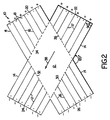
- the basic shape of the cell is of two superimposed identical rectangles at 120° angles to each other, having a common center, and placed so that the ends of the rectangles form four sides of a twelve-sided structure.
- Each rectangle has a multiplicity of small electrode pairs 18, e.g. six are shown, placed along ends 20, 22, 24 and 26 to provide the required electrical potential (shown as "+” and "-") across the box.
- the nonconductive baffles 16, 17 are disposed between electrodes 18 along each end surface, parallel to the sides of their respective rectangles.
- the baffles extend from the ends 20, 22, 24 and 26 of their respective rectangles, to the edges of the area common to the two rectangles. This common area is in the shape of a diamond, indicated by dotted lines 30, 32, 34 and 36.
- Each baffle element is oriented parallel to the length of the rectangle in which it is contained, so that the baffle element has little effect on the uniformity of an electric field set up along the length of that rectangle.
- Each baffle is positioned and arranged to limit the non uniformity of an electric field along the length of the rectangle that does not contain that baffle element.
- Each element thus extends from the end of one rectangle to the nearest edge of the other rectangle.
- each electrode is separated from all other electrodes of the same polarity by a baffle element.
- gel box 10 is wired with each electrode 18 isolated to prevent current from flowing between electrodes that are in the off state. This is accomplished by connecting each electrode through a diode 40.
- This wiring plan has the additional advantage of allowing the gel box 55 to be connected with only two wires, labelled input 1 and input 2. When input 1 is positive and input 2 negative, current will flow through one of the rectangles; when the inputs are reversed, current will flow through the other.
- This simple arrangement allows the X box to be used with an inexpensive inverting controller such as a PPI-200 (MJ Research, MA). Referring again to Fig. 1, these diodes are covered by a plastic material 33 to resuce the chances of inadvertant breakage.
- a plan for buffer recirculation ports is shown in Fig. 3.
- Small (e.g., 1-2 mm diameter) channels 42 are milled into the base of box 10 before side walls 14 are attached.
- the sections of the channels outside box 10 are covered by a plastic strip adhesively connected to box 10, giving a system that is sealed everywhere except for two ports 44.
- Buffer is pumped from one port to the other.
- the advantage of this arranagement is that the greatest amount of recirculating flow occurs where it is needed most, i.e., in the regions of the longest baffles.
- Figs. 1 and 2 when an electric potential is applied between ends 22, 24 of one of the rectangles, an electric field 38 is set up across that rectangle. Baffles in that rectangle are oriented parallel to the direction of the field, and so do not affect the field. The baffles in the unenergized rectangle, however, are oriented at a 60° angle to the field, and so constrain the electric field to a generally rectanqular shape. An electric field constrained to a generally rectangular shape is nearly uniform. Measurement of the field strength and direction in the area of a gel within an X-box with or without baffles is shown in Figs. 5-5E and 6-6C.
- FIG. 5 and 5A and 6 and 6A field strength and direction is represented by the length of each line and by the arrow head for various positions within an X-box. Without baffles field strength varies greatly, with baffles it is of uniform size and direction.
- Fig. 5B demonstrates superimposition of field strength measurements in the two electric fields, and is summarized for each X-box in Figs. 5C and 6B, respectively. This is the overall field strength and direction experienced by DNA with a gel.
- Fig. 5D provides a grid for measuring electric field strength. The results of such measurements are provided in Figs. 5E and 6C. The electric field strength in volts per centimeter is indicated. None of the measured field strengths vary by more than 3.3% from the average value for the entire gel when baffles are provided, but vary by more than 50% without the baffles. Thus, the electric field is uniform.
- a standard gel 15 is placed so that it rests on the base of a buffer-filled X-box 10, and the two rectangular fields energized alternately for equal periods of time (e.g., 10 to 60 sec.). DNA molecules migrating in the gel follow a zig-zag path with 120° turns, resulting in a net migration that is straight, shown by arrow 49.
- the principle of operation is independent of the conductivity of the buffer, the depth of the buffer in the box, and the size of the box; X-boxes can be easily scaled to any size.
- a gel box of this invention and the method of its use can be adapted for use in DNA sequencing.
- a standard sequencing gel is made between two glass plates and incorporates 0.4 mm (or thinner) plastic spacers which fit between the plates to constrain the electric fields to be uniform.
- electrophoresis is performed with the gel contained between two flat plates 60, 62 of an electrically non conducting material, such as glass.
- the two plates are held at a fixed distance apart, typically 1 mm or less, by a perimeter and baffle means 64 consisting of a thin layer of an electrically non-conducting material such as plastic.
- the perimeter and baffle means is shaped to form an outer perimeter and baffle elements as described for an X-box.
- Electrophorersis is performed with the apparatus in a horizontal position.
- the lower plate may be of any size and shape provided that it is larger in every direction than the perimeter and baffle means.
- the upper plate covers all of the perimeter and baffle means except that it provides an access 66 to the gel at each end of both rectangles so that buffer chambers (not) shown) containing buffer and an electrode can come into electrical contact with the gel. At least one buffer chamber and electrode is present at each end of each rectangle.
- the upper plate also contains a hole 68 through the upper plate for applying samples to the gel.
- the geometry is similar to that of the X-box.
- the gel material between the plates is polyacrylamide or its equivalent.
- Such an apparatus is suitable for separating DNA molecules of up to 1,500 bases and thus allows more information to be obtained regarding DNA sequence than that from a standard sequencing gel.
Abstract
Description
- This application is a continuation in part of Finney et al., U.S. Serial No. 231,821, filed August 12, 1988, entitled CONSTRAINED UNIFORM FIELD GEL ELECTROPHORESIS.
- This invention concerns apparatus for gel electrophoresis of high molecular weight DNA.
- It is known that an electric field can be used to move DNA molecules through semi-solid gels in order to separate the molecules on the basis of size. Small molecules move faster than large ones because they encounter less resistance from the gel matrix. Molecules up to about 30,000 bases in length can be separated in this way; larger molecules (up to many million bases in length) all move at about the same rate, and thus are more difficult to separate.
- Recently, a few systems have emerged that exhibit a reduction in the limitations experienced during standard electrophoresis. These systems depend on periodic changes in the direction of the electric field in the gel. For example, Cantor et al. (U.S. Patents 4,473,452 and 4,695,548) describe a system in which generally non-uniform electric fields change direction in the plane of the gel. While the mechanism by which this electrophoresis method operates to move large DNA molecules is not entirely understood, Cantor et al. propose that the application of alternating fields causes a coiled DNA molecule to be squeezed into the gel matrix by orientating itself first along the general direction of one of the fields and then along the general direction of the other, and so on. Moreover, they believe that by using gradient fields, rather than uniform fields, a shearing effect is produced that helps stretch the DNA molecule in a desired direction. Carle et al. (U.S. Patent 4,737,251) describe a method for field inversion electrophoresis. In this method, the electric field is changed in direction by 180°. Net migration is achieved by using a longer time or higher voltage in one direction than in the other direction. Chu et al. (234 Science 1582, 1986) describe a method of electrophoresis termed "contour-clamped" or "homogenous electric field" electrophoresis. This method of electrophoresis depends on a complex network of diodes and resistors to fix the electric potential at a number of points around the gel, and thus fix the electric field in the gel. This method can also be used for electrophoresis in non-uniform fields. Laas et al. (U.S. Patent 4,740,283) and a 1987 Beckman Instrument advertisement entitled GENELINETM describe a pulse field gradient gel electrophoresis apparatus having electrode arrays oriented to provide three dimensional fields across the face of the gel. Serwer (U.S. Patent 4,693,804) describes an apparatus for conducting electrophoresis in two dimensions without need to move a gel after electrophoresis in a first dimension. Barriers are provided to limit an electric field to a rectanqular shape and prevent passage of electricity. After electrophoresis in a first dimension these barriers are removed and new barriers erected to form a new electric field in a rectangular shape oriented at 90° to the first.
- This invention features an electrophoresis apparatus and method which provide good resolution of high molecular weight DNA molecules at low cost. Generally, the electrophoresis chamber of the apparatus is shaped to constrain two transversely applied electric fields such that high-molecular weight DNA is resolved in straight gel lanes by uniform electric fields. This invention can be used at a high power rating with any thickness of gel and any conductivity of buffer that is normally used for gel electrophoresis, including gels useful for preparative and high sensitivity work. Buffers of high conductivity are especially preferred for resolution of high molecular weight DNA. Power consumption may also be maintained at a low enough level to require only inexpensive power supplies that are commonly used for DNA gel electrophoresis. The gel may be sized as required, the limitation being physical, rather than electrical.
- Thus, the invention features, in a first aspect, gel electrophoresis apparatus for separating DNA molecules of high molecular weight having means for generating first and second electric fields, the fields being oriented transversely to each other, and a gel box shaped and contoured to simultaneously form both the electric fields into generally uniform electric fields.
- By "uniform electric field" is meant that the electric field strength (in volts/cm) generated in the gel box varies by less than 20% from an average value in the gel box, preferably less than 10% and even more preferably less than 5%, particularly in the area of the gel box in which a DNA sample is placed and electrophoresed. By "simultaneously" is meant that the gel box is shaped and contoured to form both of the electric fields into uniform electric fields without need for the gel box to be altered in its shape or contouring when the means is switched to generate either electric field.
- In preferred embodiments, the means includes at least four electrodes positioned near the outer perimeter of the box which is defined by a wall forming the shape of the box. The outer perimeter is shaped to accept a gel and buffer, the perimeter having the shape of two rectangles placed on top of each other at an angle of between 90° and 135°, preferably the rectangles are identical in shape, and at least one corner of one rectangle coincides with a corner of the other rectangle, most preferably the rectangles coincide at two corners. The gel box includes at least one baffle means formed of electrically non-conducting material positioned and arranged to limit formation of a non-uniform electric field in the gel box. Generally, the baffle means is oriented along the overall direction of the first electric field, and is positioned and arranged to limit formation of a non-uniform field in the second electric field; most preferably, the baffle means is a set of baffle elements and the apparatus has a plurality of these baffle elements, with at least one baffle element, but preferably all baffle elements, oriented along the overall direction of the first or second electric field to prevent formation of a non-uniform electric field in the other electric field. The baffle means is preferably in contact with the outer perimeter and base of the gel box, and has a height equal to that of the gel box. Most preferably, each baffle element is in contact with the outer perimeter of the gel box and extends along the direction of the first or second uniform electric field to the edge of the other uniform electric field. Each electrode is generally separated from all other electrodes of the same polarity by a baffle formed of electrically non-conducting material, the baffle preventing direct electric conduction between these electrodes through a medium in the gel box. In another preferred embodiment, the apparatus is suitable for use in DNA sequencing, having two plates and a baffle means positioned to sandwich a polyacrylamide gel.
- In a second aspect, the invention features a method for separating DNA molecules of high molecular weight, including the steps of positioning the DNA molecules within a gel matrix; providing means for generating alternating transversely applied uniform electric fields, and positioning the gel matrix in a gel box sized, shaped, and contoured to simultaneously form two generally transverse uniform electric fields, and subjecting the gel matrix to these alternating electric fields.
- Other features and advantages of the invention will be apparent from the following description of the preferred embodiments thereof, and from the claims.
- The drawings will first briefly be described.
-
- Figs. 1 and 2 are an isometric view and a top view respectively of an electrophoresis cell of the invention;
- Fig. 3 is a diagrammatic representation showing recirculation ports in an electrophoresis cell;
- Fig. 4 is a schematic diagram of the wiring of an electrophoresis cell;
- Figs. 5, 5A, and 5B are top views of an electrophoresis cell without baffles showing field strength and direction during electrophoresis in a region of the cell, Fig. 5C shows the vector sum of these field strengths, Fig. 5D shows a grid layout used for measuring the field strength, and Fig. 5E shows numerical values of field strengths in V/cm in one electric field;
- Figs. 6 and 6A are top views of an electrophoresis cell with baffles showing field strength and direction during electrophoresis in a region of the cell, Fig. 6B shows the vector sum of the field strengths, and Fig. 6C show numerical values of field strength in V/cm in one electric field.
- Fig. 7 is an isometric view of an electrophoresis cell suitable for use in DNA sequencing.
- One example of an electrophoresis cell useful in this invention generally has an X-shape, and is termed an X-box. Two uniform electric fields which alternate at a 120° angle to each other are provided. Uniformity of fields is achieved by the shape of the electrophoresis cell of the invention.
- Referring to Figs. 1 and 2,
X-box 10 has aflat base 12 of an electrically non-conducting material, such as acrylic plastic.Vertical walls 14 in combination withends gel 15 and buffer.Baffle elements ends ends - The basic shape of the cell is of two superimposed identical rectangles at 120° angles to each other, having a common center, and placed so that the ends of the rectangles form four sides of a twelve-sided structure. Each rectangle has a multiplicity of small electrode pairs 18, e.g. six are shown, placed along ends 20, 22, 24 and 26 to provide the required electrical potential (shown as "+" and "-") across the box. The nonconductive baffles 16, 17 are disposed between
electrodes 18 along each end surface, parallel to the sides of their respective rectangles. The baffles extend from theends dotted lines - Referring to Fig. 4,
gel box 10 is wired with eachelectrode 18 isolated to prevent current from flowing between electrodes that are in the off state. This is accomplished by connecting each electrode through adiode 40. This wiring plan has the additional advantage of allowing the gel box 55 to be connected with only two wires, labelledinput 1 andinput 2. Wheninput 1 is positive andinput 2 negative, current will flow through one of the rectangles; when the inputs are reversed, current will flow through the other. This simple arrangement allows the X box to be used with an inexpensive inverting controller such as a PPI-200 (MJ Research, MA). Referring again to Fig. 1, these diodes are covered by aplastic material 33 to resuce the chances of inadvertant breakage. - To maintain temperature and pH uniformity of buffer in
gel box 10, it is desirable to recirculate the buffer used for running a gel. The channels through which the buffer is recirculated are kept narrow so that very little current flows through them. By way of example only, a plan for buffer recirculation ports is shown in Fig. 3. Small (e.g., 1-2 mm diameter)channels 42 are milled into the base ofbox 10 beforeside walls 14 are attached. The sections of the channels outsidebox 10 are covered by a plastic strip adhesively connected tobox 10, giving a system that is sealed everywhere except for twoports 44. Buffer is pumped from one port to the other. The advantage of this arranagement is that the greatest amount of recirculating flow occurs where it is needed most, i.e., in the regions of the longest baffles. - Referring to Figs. 1 and 2, when an electric potential is applied between ends 22, 24 of one of the rectangles, an
electric field 38 is set up across that rectangle. Baffles in that rectangle are oriented parallel to the direction of the field, and so do not affect the field. The baffles in the unenergized rectangle, however, are oriented at a 60° angle to the field, and so constrain the electric field to a generally rectanqular shape. An electric field constrained to a generally rectangular shape is nearly uniform. Measurement of the field strength and direction in the area of a gel within an X-box with or without baffles is shown in Figs. 5-5E and 6-6C. These figures demonstrate that when baffles are provided the field strength is uniform to within 3.3% in the gel box the area of the gel, and without baffles may vary by as much as 50%. In Figs. 5 and 5A and 6 and 6A field strength and direction is represented by the length of each line and by the arrow head for various positions within an X-box. Without baffles field strength varies greatly, with baffles it is of uniform size and direction. Fig. 5B demonstrates superimposition of field strength measurements in the two electric fields, and is summarized for each X-box in Figs. 5C and 6B, respectively. This is the overall field strength and direction experienced by DNA with a gel. For a box without baffles the field strength and direction is significantly distorted from a straight line, while for a box with baffles the field strength and direction is not distorted. Fig. 5D provides a grid for measuring electric field strength. The results of such measurements are provided in Figs. 5E and 6C. The electric field strength in volts per centimeter is indicated. None of the measured field strengths vary by more than 3.3% from the average value for the entire gel when baffles are provided, but vary by more than 50% without the baffles. Thus, the electric field is uniform. - Referring to Fig. 1, a
standard gel 15 is placed so that it rests on the base of a buffer-filledX-box 10, and the two rectangular fields energized alternately for equal periods of time (e.g., 10 to 60 sec.). DNA molecules migrating in the gel follow a zig-zag path with 120° turns, resulting in a net migration that is straight, shown by arrow 49. - The principle of operation is independent of the conductivity of the buffer, the depth of the buffer in the box, and the size of the box; X-boxes can be easily scaled to any size.
- Other embodiments are within the following claims. For example, a gel box of this invention and the method of its use can be adapted for use in DNA sequencing. A standard sequencing gel is made between two glass plates and incorporates 0.4 mm (or thinner) plastic spacers which fit between the plates to constrain the electric fields to be uniform. For example, referring to Fig. 7, electrophoresis is performed with the gel contained between two
flat plates access 66 to the gel at each end of both rectangles so that buffer chambers (not) shown) containing buffer and an electrode can come into electrical contact with the gel. At least one buffer chamber and electrode is present at each end of each rectangle. The upper plate also contains a hole 68 through the upper plate for applying samples to the gel. The geometry is similar to that of the X-box. The gel material between the plates is polyacrylamide or its equivalent. Such an apparatus is suitable for separating DNA molecules of up to 1,500 bases and thus allows more information to be obtained regarding DNA sequence than that from a standard sequencing gel. - Where technical features mentioned in any claim are followed by reference signs, those reference signs have been included for the sole purpose of increasing the intelligibility of the claims and accordingly, such reference signs do not have any limiting effect on the scope of each element identified by way of example by such reference signs.
Claims (19)
means for generating a first electric field and a second electric field, said fields being oriented transversely to each other, and
a gel box shaped and contoured to simultaneously form both said first and second fields into generally uniform electric fields.
positioning said DNA molecules within a gel matrix,
providing means for generating alternating, transversely applied uniform electric fields, and
positioning said gel matrix in a gel box shaped and contoured to simultaneously form two generally transverse uniform electric fields and subjecting said gel matrix to said alternating electric fields.
Priority Applications (1)
| Application Number | Priority Date | Filing Date | Title |
|---|---|---|---|
| AT89114817T ATE95925T1 (en) | 1988-08-12 | 1989-08-10 | FORCED UNIFORM FIELD GEL ELECTROPHORESIS. |
Applications Claiming Priority (4)
| Application Number | Priority Date | Filing Date | Title |
|---|---|---|---|
| US23182188A | 1988-08-12 | 1988-08-12 | |
| US231821 | 1988-08-12 | ||
| US07/289,966 US5011586A (en) | 1988-08-12 | 1988-12-23 | Constrained uniform field gel electrophoresis |
| US289966 | 1988-12-23 |
Publications (3)
| Publication Number | Publication Date |
|---|---|
| EP0361046A2 true EP0361046A2 (en) | 1990-04-04 |
| EP0361046A3 EP0361046A3 (en) | 1991-09-11 |
| EP0361046B1 EP0361046B1 (en) | 1993-10-13 |
Family
ID=26925465
Family Applications (1)
| Application Number | Title | Priority Date | Filing Date |
|---|---|---|---|
| EP89114817A Expired - Lifetime EP0361046B1 (en) | 1988-08-12 | 1989-08-10 | Constrained uniform field gel electrophoresis |
Country Status (4)
| Country | Link |
|---|---|
| US (1) | US5011586A (en) |
| EP (1) | EP0361046B1 (en) |
| JP (1) | JP3025780B2 (en) |
| DE (1) | DE68909878T2 (en) |
Cited By (7)
| Publication number | Priority date | Publication date | Assignee | Title |
|---|---|---|---|---|
| WO1991012904A1 (en) * | 1990-02-28 | 1991-09-05 | Soane Technologies, Inc. | Method and device for moving molecules by the application of a plurality of electrical fields |
| EP0475683A2 (en) * | 1990-09-12 | 1992-03-18 | Beckman Instruments, Inc. | Electrophoresis with electrode baffles |
| WO1992008969A1 (en) * | 1990-11-09 | 1992-05-29 | Elchrom Ltd | Apparatus and method for submerged gel electrophoresis |
| US5645702A (en) * | 1995-06-07 | 1997-07-08 | Hewlett-Packard Company | Low voltage miniaturized column analytical apparatus and method |
| US5750015A (en) * | 1990-02-28 | 1998-05-12 | Soane Biosciences | Method and device for moving molecules by the application of a plurality of electrical fields |
| WO2000073780A1 (en) * | 1999-05-28 | 2000-12-07 | Proteologics, Inc. | Methods and apparatus for nonlinear mobility electrophoresis separation |
| US6808609B1 (en) | 1990-02-28 | 2004-10-26 | Aclara Biosciences, Inc. | Device and method for moving charged particles |
Families Citing this family (14)
| Publication number | Priority date | Publication date | Assignee | Title |
|---|---|---|---|---|
| US5935401A (en) * | 1996-09-18 | 1999-08-10 | Aclara Biosciences | Surface modified electrophoretic chambers |
| US5453162A (en) * | 1993-09-09 | 1995-09-26 | University Of North Carolina At Chapel Hill | Method and apparatus for gel electrophoresis using two electric fields |
| US6176990B1 (en) * | 1995-06-08 | 2001-01-23 | Visible Genetics Inc. | Micro-electrophoresis chip for moving and separating nucleic acids and other charged molecules |
| US6682641B1 (en) * | 1999-04-26 | 2004-01-27 | Mj Research, Inc. | Electrophoresis assembly and method of casting electrophoresis gels |
| AU6574601A (en) * | 2000-06-07 | 2001-12-17 | Centro Nacional De Investigaciones Cientificas (Cnic) | Pulsed field electrophoresis chambers, accessories and method of utilization for seperation of DNA molecules |
| AU2002230979A1 (en) * | 2000-12-18 | 2002-07-01 | Trustees Of Princeton University | Fractionation of macro-molecules using asymmetric pulsed field electrophoresis |
| US7597791B2 (en) * | 2001-10-19 | 2009-10-06 | The Trustees Of Princeton University | Method and apparatus for generating electric fields and flow distributions for rapidly separating molecules |
| US20070090026A1 (en) * | 2005-10-06 | 2007-04-26 | Jongyoon Han | Continuous biomolecule separation in a nanofilter |
| US20090286694A1 (en) * | 2006-08-21 | 2009-11-19 | Gafur Zainiev | Nucleic acid array with releaseable nucleic acid probes |
| US20100056388A1 (en) * | 2006-08-21 | 2010-03-04 | Cnvgenes, Inc. | Nucleic acid array having fixed nucleic acid anti-probes and complementary free nucleic acid probes |
| US20080044821A1 (en) * | 2006-08-21 | 2008-02-21 | Gafur Zainiev | Nucleic acid array having fixed nucleic acid anti-probes and complementary free nucleic acid probes |
| US20080044822A1 (en) * | 2006-08-21 | 2008-02-21 | Gafur Zainiev | Nucleic acid array with releaseable nucleic acid probes |
| CZ306860B6 (en) * | 2008-05-30 | 2017-08-16 | Masarykova Univerzita | A method and a device for conducting electrophoresis |
| EP3350310B1 (en) | 2015-09-18 | 2019-05-22 | Okinawa Institute of Science and Technology School Corporation | 3d polymeric insert to apply uniform electric field in circular cultureware |
Citations (4)
| Publication number | Priority date | Publication date | Assignee | Title |
|---|---|---|---|---|
| US4148703A (en) * | 1976-02-11 | 1979-04-10 | Morton Weintraub | Method of electrophoretic purification of enzymes and peptides by means of an adjustable, specialized, geometrically located electrode system |
| WO1984002001A1 (en) * | 1982-11-18 | 1984-05-24 | Univ Columbia | Electrophoresis using alternating transverse electric fields |
| WO1988010423A1 (en) * | 1987-06-19 | 1988-12-29 | Institut Molekulyarnoi Biologii Akademii Nauk Sssr | Apparatus for electrophoretic separation of high-molecular dna in a gel |
| EP0307332A2 (en) * | 1987-09-07 | 1989-03-15 | ARI S.A. Société Anonyme dite: | Method and apparatus for the electrophoresis of very big macromolecules |
Family Cites Families (5)
| Publication number | Priority date | Publication date | Assignee | Title |
|---|---|---|---|---|
| US4695548A (en) * | 1982-11-18 | 1987-09-22 | The Trustees Of Columbia University In The City Of New York | Gel inserts useful in electrophoresis |
| US4693804A (en) * | 1984-12-19 | 1987-09-15 | Board Of Regents, The University Of Texas System | Apparatus for bidimensional electrophoretic separations |
| US4737251A (en) * | 1985-09-27 | 1988-04-12 | Washington University | Field-inversion gel electrophoresis |
| US4614576A (en) * | 1985-10-22 | 1986-09-30 | Ionics, Incorporated | Microliter scale electrodialysis apparatus |
| US4740283A (en) * | 1986-02-27 | 1988-04-26 | University Patents, Inc. | Pulsed-field gradient gel electrophoretic apparatus |
-
1988
- 1988-12-23 US US07/289,966 patent/US5011586A/en not_active Expired - Lifetime
-
1989
- 1989-08-10 EP EP89114817A patent/EP0361046B1/en not_active Expired - Lifetime
- 1989-08-10 DE DE89114817T patent/DE68909878T2/en not_active Expired - Fee Related
- 1989-08-14 JP JP1209988A patent/JP3025780B2/en not_active Expired - Fee Related
Patent Citations (4)
| Publication number | Priority date | Publication date | Assignee | Title |
|---|---|---|---|---|
| US4148703A (en) * | 1976-02-11 | 1979-04-10 | Morton Weintraub | Method of electrophoretic purification of enzymes and peptides by means of an adjustable, specialized, geometrically located electrode system |
| WO1984002001A1 (en) * | 1982-11-18 | 1984-05-24 | Univ Columbia | Electrophoresis using alternating transverse electric fields |
| WO1988010423A1 (en) * | 1987-06-19 | 1988-12-29 | Institut Molekulyarnoi Biologii Akademii Nauk Sssr | Apparatus for electrophoretic separation of high-molecular dna in a gel |
| EP0307332A2 (en) * | 1987-09-07 | 1989-03-15 | ARI S.A. Société Anonyme dite: | Method and apparatus for the electrophoresis of very big macromolecules |
Non-Patent Citations (1)
| Title |
|---|
| INTERNATIONAL LABORATORY, vol. 18, no. 6, July-August 1988, pages 40-46, Shelton, CT, US; L. DE CEUSTER: "Pulsed field electrophoresis with a universal submarine system" * |
Cited By (12)
| Publication number | Priority date | Publication date | Assignee | Title |
|---|---|---|---|---|
| WO1991012904A1 (en) * | 1990-02-28 | 1991-09-05 | Soane Technologies, Inc. | Method and device for moving molecules by the application of a plurality of electrical fields |
| US5126022A (en) * | 1990-02-28 | 1992-06-30 | Soane Tecnologies, Inc. | Method and device for moving molecules by the application of a plurality of electrical fields |
| AU637895B2 (en) * | 1990-02-28 | 1993-06-10 | Soane Technologies, Inc. | Method and device for moving molecules by the application of a plurality of electrical fields |
| US5750015A (en) * | 1990-02-28 | 1998-05-12 | Soane Biosciences | Method and device for moving molecules by the application of a plurality of electrical fields |
| US6306272B1 (en) | 1990-02-28 | 2001-10-23 | Soane Biosciences, Inc. | Method and device for performing chemical reactions |
| US6808609B1 (en) | 1990-02-28 | 2004-10-26 | Aclara Biosciences, Inc. | Device and method for moving charged particles |
| US6964735B2 (en) | 1990-02-28 | 2005-11-15 | Aclara Biosciences, Inc. | Method for moving charged particles |
| EP0475683A2 (en) * | 1990-09-12 | 1992-03-18 | Beckman Instruments, Inc. | Electrophoresis with electrode baffles |
| EP0475683A3 (en) * | 1990-09-12 | 1993-02-24 | Beckman Instruments, Inc. | Electrophoresis with electrode baffles |
| WO1992008969A1 (en) * | 1990-11-09 | 1992-05-29 | Elchrom Ltd | Apparatus and method for submerged gel electrophoresis |
| US5645702A (en) * | 1995-06-07 | 1997-07-08 | Hewlett-Packard Company | Low voltage miniaturized column analytical apparatus and method |
| WO2000073780A1 (en) * | 1999-05-28 | 2000-12-07 | Proteologics, Inc. | Methods and apparatus for nonlinear mobility electrophoresis separation |
Also Published As
| Publication number | Publication date |
|---|---|
| DE68909878D1 (en) | 1993-11-18 |
| EP0361046A3 (en) | 1991-09-11 |
| JP3025780B2 (en) | 2000-03-27 |
| US5011586A (en) | 1991-04-30 |
| JPH02176456A (en) | 1990-07-09 |
| DE68909878T2 (en) | 1994-02-10 |
| EP0361046B1 (en) | 1993-10-13 |
Similar Documents
| Publication | Publication Date | Title |
|---|---|---|
| EP0361046B1 (en) | Constrained uniform field gel electrophoresis | |
| JP2744293B2 (en) | Electrophoresis device | |
| US5173159A (en) | Multiple electrophoresis method for the controlled migration of macromolecules through rectangular gel plates | |
| US4740283A (en) | Pulsed-field gradient gel electrophoretic apparatus | |
| US20010023825A1 (en) | Methods and apparatus for nonlinear mobility electrophoresis separation | |
| US4911817A (en) | Electrophoresis apparatus | |
| Svoboda et al. | Rapid electrotransfer of proteins from polyacrylamide gel to nitrocellulose membrane using surface-conductive glass as anode | |
| US5102524A (en) | Multiple electrophoresis device for the controlled migration of macromolecules through rectangular gel plates | |
| US5176805A (en) | Reverse-polarity gel electrophoresis | |
| EP0327363A2 (en) | Separation of large DNA molecules in alternating asymmetric electric fields | |
| EP0256737B1 (en) | Electrophoresis using contour-clamped homogeneous or inhomogeneous electric fields | |
| EP0510146B1 (en) | Apparatus and method for submerged gel electrophoresis | |
| JP3411925B2 (en) | Notched spacer for slab gel electrophoresis | |
| EP1615026A2 (en) | A traveling wave grid module and an electrophoretic cell having a plurality of traveling wave modules | |
| McPeek Jr et al. | Separation of large DNA molecules by modified pulsed field gradient gel electrophoresis | |
| US5549796A (en) | Electrophoresis using contour-clamped electric fields | |
| EP1211510A1 (en) | Methods and apparatus for nonlinear mobility electrophoresis separation | |
| CN2031929U (en) | Electrophoretic tank capable of generating equal-strength alternating current field | |
| JP3342745B2 (en) | Electrophoresis device | |
| JPH03167468A (en) | Multielectrode electrophoretic apparatus | |
| EP0745844A2 (en) | Apparatus for separating DNA molecules of chromosomal size by electrophoresis | |
| JPH01147355A (en) | Molecular sieve unit | |
| JPH01260356A (en) | Sample coating for electrophoresis | |
| JPH07113786A (en) | Electrophoresis device | |
| JPS63246649A (en) | Apparatus and method for electrophoresis |
Legal Events
| Date | Code | Title | Description |
|---|---|---|---|
| PUAI | Public reference made under article 153(3) epc to a published international application that has entered the european phase |
Free format text: ORIGINAL CODE: 0009012 |
|
| AK | Designated contracting states |
Kind code of ref document: A2 Designated state(s): AT BE CH DE ES FR GB GR IT LI LU NL SE |
|
| PUAL | Search report despatched |
Free format text: ORIGINAL CODE: 0009013 |
|
| AK | Designated contracting states |
Kind code of ref document: A3 Designated state(s): AT BE CH DE ES FR GB GR IT LI LU NL SE |
|
| 17P | Request for examination filed |
Effective date: 19920214 |
|
| 17Q | First examination report despatched |
Effective date: 19920506 |
|
| GRAA | (expected) grant |
Free format text: ORIGINAL CODE: 0009210 |
|
| AK | Designated contracting states |
Kind code of ref document: B1 Designated state(s): AT BE CH DE ES FR GB GR IT LI LU NL SE |
|
| PG25 | Lapsed in a contracting state [announced via postgrant information from national office to epo] |
Ref country code: ES Free format text: THE PATENT HAS BEEN ANNULLED BY A DECISION OF A NATIONAL AUTHORITY Effective date: 19931013 Ref country code: AT Effective date: 19931013 Ref country code: GR Free format text: LAPSE BECAUSE OF FAILURE TO SUBMIT A TRANSLATION OF THE DESCRIPTION OR TO PAY THE FEE WITHIN THE PRESCRIBED TIME-LIMIT Effective date: 19931013 Ref country code: BE Effective date: 19931013 |
|
| REF | Corresponds to: |
Ref document number: 95925 Country of ref document: AT Date of ref document: 19931015 Kind code of ref document: T |
|
| REF | Corresponds to: |
Ref document number: 68909878 Country of ref document: DE Date of ref document: 19931118 |
|
| ITF | It: translation for a ep patent filed |
Owner name: MODIANO & ASSOCIATI S.R.L. |
|
| ET | Fr: translation filed | ||
| PLBE | No opposition filed within time limit |
Free format text: ORIGINAL CODE: 0009261 |
|
| STAA | Information on the status of an ep patent application or granted ep patent |
Free format text: STATUS: NO OPPOSITION FILED WITHIN TIME LIMIT |
|
| PG25 | Lapsed in a contracting state [announced via postgrant information from national office to epo] |
Ref country code: LU Free format text: LAPSE BECAUSE OF NON-PAYMENT OF DUE FEES Effective date: 19940831 |
|
| 26N | No opposition filed | ||
| EAL | Se: european patent in force in sweden |
Ref document number: 89114817.3 |
|
| PGFP | Annual fee paid to national office [announced via postgrant information from national office to epo] |
Ref country code: NL Payment date: 19970923 Year of fee payment: 9 |
|
| PGFP | Annual fee paid to national office [announced via postgrant information from national office to epo] |
Ref country code: CH Payment date: 19971002 Year of fee payment: 9 |
|
| PG25 | Lapsed in a contracting state [announced via postgrant information from national office to epo] |
Ref country code: CH Free format text: LAPSE BECAUSE OF NON-PAYMENT OF DUE FEES Effective date: 19980831 Ref country code: LI Free format text: LAPSE BECAUSE OF NON-PAYMENT OF DUE FEES Effective date: 19980831 |
|
| PG25 | Lapsed in a contracting state [announced via postgrant information from national office to epo] |
Ref country code: NL Free format text: LAPSE BECAUSE OF NON-PAYMENT OF DUE FEES Effective date: 19990301 |
|
| REG | Reference to a national code |
Ref country code: CH Ref legal event code: PL |
|
| NLV4 | Nl: lapsed or anulled due to non-payment of the annual fee |
Effective date: 19990301 |
|
| REG | Reference to a national code |
Ref country code: GB Ref legal event code: IF02 |
|
| PGFP | Annual fee paid to national office [announced via postgrant information from national office to epo] |
Ref country code: GB Payment date: 20050714 Year of fee payment: 17 |
|
| PGFP | Annual fee paid to national office [announced via postgrant information from national office to epo] |
Ref country code: FR Payment date: 20050804 Year of fee payment: 17 |
|
| PGFP | Annual fee paid to national office [announced via postgrant information from national office to epo] |
Ref country code: SE Payment date: 20050805 Year of fee payment: 17 |
|
| PG25 | Lapsed in a contracting state [announced via postgrant information from national office to epo] |
Ref country code: IT Free format text: LAPSE BECAUSE OF NON-PAYMENT OF DUE FEES;WARNING: LAPSES OF ITALIAN PATENTS WITH EFFECTIVE DATE BEFORE 2007 MAY HAVE OCCURRED AT ANY TIME BEFORE 2007. THE CORRECT EFFECTIVE DATE MAY BE DIFFERENT FROM THE ONE RECORDED. Effective date: 20050810 |
|
| PGFP | Annual fee paid to national office [announced via postgrant information from national office to epo] |
Ref country code: DE Payment date: 20050831 Year of fee payment: 17 |
|
| PG25 | Lapsed in a contracting state [announced via postgrant information from national office to epo] |
Ref country code: SE Free format text: LAPSE BECAUSE OF NON-PAYMENT OF DUE FEES Effective date: 20060811 |
|
| REG | Reference to a national code |
Ref country code: GB Ref legal event code: 732E |
|
| REG | Reference to a national code |
Ref country code: FR Ref legal event code: TP |
|
| PG25 | Lapsed in a contracting state [announced via postgrant information from national office to epo] |
Ref country code: DE Free format text: LAPSE BECAUSE OF NON-PAYMENT OF DUE FEES Effective date: 20070301 |
|
| EUG | Se: european patent has lapsed | ||
| GBPC | Gb: european patent ceased through non-payment of renewal fee |
Effective date: 20060810 |
|
| REG | Reference to a national code |
Ref country code: FR Ref legal event code: ST Effective date: 20070430 |
|
| PG25 | Lapsed in a contracting state [announced via postgrant information from national office to epo] |
Ref country code: GB Free format text: LAPSE BECAUSE OF NON-PAYMENT OF DUE FEES Effective date: 20060810 |
|
| PG25 | Lapsed in a contracting state [announced via postgrant information from national office to epo] |
Ref country code: FR Free format text: LAPSE BECAUSE OF NON-PAYMENT OF DUE FEES Effective date: 20060831 |
|
| PGFP | Annual fee paid to national office [announced via postgrant information from national office to epo] |
Ref country code: IT Payment date: 20070929 Year of fee payment: 19 |
|
| PGRI | Patent reinstated in contracting state [announced from national office to epo] |
Ref country code: IT Effective date: 20091201 |
|
| PGRI | Patent reinstated in contracting state [announced from national office to epo] |
Ref country code: IT Effective date: 20091201 |