EP0360899A1 - Queue comprising a plurality of memory elements - Google Patents
Queue comprising a plurality of memory elements Download PDFInfo
- Publication number
- EP0360899A1 EP0360899A1 EP88116010A EP88116010A EP0360899A1 EP 0360899 A1 EP0360899 A1 EP 0360899A1 EP 88116010 A EP88116010 A EP 88116010A EP 88116010 A EP88116010 A EP 88116010A EP 0360899 A1 EP0360899 A1 EP 0360899A1
- Authority
- EP
- European Patent Office
- Prior art keywords
- entry
- memory element
- storage
- information
- queue
- Prior art date
- Legal status (The legal status is an assumption and is not a legal conclusion. Google has not performed a legal analysis and makes no representation as to the accuracy of the status listed.)
- Granted
Links
Images
Classifications
-
- G—PHYSICS
- G06—COMPUTING; CALCULATING OR COUNTING
- G06F—ELECTRIC DIGITAL DATA PROCESSING
- G06F5/00—Methods or arrangements for data conversion without changing the order or content of the data handled
- G06F5/06—Methods or arrangements for data conversion without changing the order or content of the data handled for changing the speed of data flow, i.e. speed regularising or timing, e.g. delay lines, FIFO buffers; over- or underrun control therefor
- G06F5/10—Methods or arrangements for data conversion without changing the order or content of the data handled for changing the speed of data flow, i.e. speed regularising or timing, e.g. delay lines, FIFO buffers; over- or underrun control therefor having a sequence of storage locations each being individually accessible for both enqueue and dequeue operations, e.g. using random access memory
- G06F5/12—Means for monitoring the fill level; Means for resolving contention, i.e. conflicts between simultaneous enqueue and dequeue operations
- G06F5/14—Means for monitoring the fill level; Means for resolving contention, i.e. conflicts between simultaneous enqueue and dequeue operations for overflow or underflow handling, e.g. full or empty flags
-
- G—PHYSICS
- G06—COMPUTING; CALCULATING OR COUNTING
- G06F—ELECTRIC DIGITAL DATA PROCESSING
- G06F2205/00—Indexing scheme relating to group G06F5/00; Methods or arrangements for data conversion without changing the order or content of the data handled
- G06F2205/06—Indexing scheme relating to groups G06F5/06 - G06F5/16
- G06F2205/064—Linked list, i.e. structure using pointers, e.g. allowing non-contiguous address segments in one logical buffer or dynamic buffer space allocation
Definitions
- the invention relates to a queue consisting of a plurality of storage elements for the temporary storage of information to be forwarded to a receiver and a controller for the storage and retrieval of the information, the information being forwarded in the order in which it was buffered (FIFO principle).
- Queues are often used as buffers and feeders for data processing or process control devices, in order to be able to process information from multiple sources and intended for a common sink in sequence.
- a cyclically operating access memory is then simulated from memory elements freely available in a memory unit, which are linked in a manner known per se via forward and reverse addresses to form a ring chain.
- each storage element has a control entry field which, in the case of a subsequent storage element of the chain, which is ready to hold information, always points to this next free storage element in accordance with the entry in the address entry field for the forward link.
- the next storage element that is ready for storage is marked by an entry pointer and the next occupied storage element that is pending for storage is marked by a discharge pointer.
- the associated pointer is set to the address for the next storage element in the ring chain, the new address being able to be taken directly from the address entry field for the forward link of the operated storage element. No additional cyclical input and output counters are required for address management.
- the blocking entry can be passed on from storage element to storage element in a simple manner on the basis of the address entries, starting from the storage element identified by the discharge pointer.
- whether a data can be saved after calling it depends solely on whether it was previously saved. This can be done using the discharge pointer by checking the data field of the associated memory element. On the other hand, an entry field provided at the beginning of the data field for identifying the “free” or “occupied” state is more advantageous. In any case, an unused data field also indicates that the entire queue is empty. This is particularly advantageous if several queues have to be checked one after the other for the presence of a storage.
- the lock entry is first transferred immediately after a withdrawal takes effect, before the actual forwarding of the intermediate storage information is provided.
- the storage element previously blocked by the lock entry is thus available at an early stage to accept a further storage request, so that the risk that a storage request must be rejected is reduced. This is particularly advantageous if the withdrawal and injection processes are overlapping.
- the new solution principle is particularly suitable for queues which can be expanded dynamically by chaining in new storage elements if a storage element with a lock entry is controlled by the entry pointer.
- the lock entry then does not prevent the desired temporary storage, but leads to the chaining of a new storage element after the locked storage element, the new storage element taking over the locking entry and thus releasing the previously locked storage element for temporary storage as soon as the chain link is restored again by adapting the address entries in the affected storage elements is made.
- the queues can be shortened dynamically. If the memory element following the memory element that was released last is free, then no further information to be forwarded is stored in the entire queue. The memory element which is released can therefore be outsourced if the queue has not already shrunk to the minimum number of two chain links, which can be checked in a simple manner by comparing address entries.
- each storage element has three entry fields for the information to be buffered, namely an address entry field for the address AD-NEL, which refers to the beginning of the data field in the preceding storage element, an address entry field for the address AD-VEL, which refers to the Address entry field for the forward link of the subsequent storage element points, and a control entry field CONTF.
- This control entry field either contains the address AD-NEL from the associated address entry field for the forward link and thus points to the next storage element ready for the temporary storage of information, or it contains a lock entry F which indicates the end of the assignable queue and leads to the rejection of a further buffering request .
- the entry pointer EP ... is directed in each case to the control entry field CONTF, while the discharge pointer AP ... is directed in each case to the start of the data field DF, the respective address resulting from the address for the storage element and a corresponding distance address.
- the entry pointer EP1 for the first buffering request points to the storage element EL1
- the discharge pointer AP1 for the first withdrawal is directed to the storage element EL2
- the storage element EL3 consequently carries the lock entry F. Consequently, in the first buffering request the current entry pointer EP1 becomes Storage elements EL2 occupy what is indicated by the additional entry (E1) in the associated data field DF, while the storage element EL3 is occupied in the second buffering request by the entry pointer EP2. If a third intermediate storage request would then arrive before the first occupied storage element EL2 is free again, then the lock entry F that can be reached via the current entry pointer EP3 would make this effective and the request would be rejected because the queue no longer has an allocable storage element.
- the memory element EL1 is still free. However, this must remain free so that after the queue becomes empty, the current entry pointer EP ... always points to the predecessor element to the current discharge pointer AP ... in order to ensure that the queue functions reliably. Otherwise, as with the known arrangements, one would have to take separate measures to create an overtaking lock.
- this free storage element e.g. EL1
- the release already takes place at the beginning of a relocation to be initiated. This is indicated in FIG 2.
- the withdrawal is initiated, which is indicated by the arrow on the framed information entry (E1).
- the lock entry F has thus been forwarded from the storage element EL3 to the cyclically following storage element EL1, so that a subsequent third buffering request via the entry pointer EP3 is no longer rejected, but is instead forwarded to the storage element EL1.
- a subsequent fourth buffering request via the entry pointer EP4 would be rejected. According to FIG. 3, this would only come into play when the discharge pointer AP1 changed over to the discharge pointer AP2 at the end of the first withdrawal and a new withdrawal request has arrived, according to which the second withdrawal would have already been initiated; etc..
- the storage elements EL ... and entry fields affected by the forwarding of the lock entry F are identified by corner triangles in FIG. 2 and FIG. 3.
- the preceding memory element ELn-1 is determined as the memory element ELn on the basis of the address entry AD-VEL, and the lock entry F is made in the control entry field CONTF.
- the preceding memory element ELn-2 is then determined on the basis of the address AD-VEL in this memory element and the address AD-NEL is transferred there from the address entry field there into the control entry field CONTF.
- the lock entry in this tax entry field is now deleted. Instead, reference is made to the element ELn-1 as a recordable storage element.
- control effort for this is relatively low and can be implemented in a simple manner in the case of appropriately program-controlled devices.
- the length of the queues cannot be predicted from the outset. If the number of predefined storage elements is chosen too small, there is a risk that too many intermediate storage requests must be rejected. On the other hand, if the number is too large, unnecessary storage capacity is tied up. It is therefore advantageous if the queue can be expanded in accordance with the respective operational requirements with regard to the number of its storage elements.
- FIG. 4 This case is shown in FIG. 4 starting from the queue in FIG. 2.
- the buffering request relating to the entry pointer EP4 does not lead to a rejection of the buffering request, but rather to chain a fourth storage element EL4 into the queue on the basis of the entry ON in the controlled control entry field.
- the entries in the storage elements concerned must be supplemented or changed.
- Three memory elements are concerned in each case, namely the memory element EL4 to be newly chained, the memory element EL1 which triggers the chaining and the memory element EL2 which has hitherto followed this.
- the affected entry fields of these memory elements EL4, EL1 and EL2 are again identified by corner triangles.
- an available storage element ELn is first selected in the memory and the chaining notice "ON" is entered in its control entry field CONTF.
- the current entry pointer e.g. EP4
- labeled memory element e.g. EL1 as ELn-1
- the reference address to the newly linked memory element EL4 is entered as the memory element ELn-1 in the entry field for the forward address AD-NEL and in the control entry field CONTF.
- the new storage element EL4 is thus integrated into the existing chain, with the previously locking storage element EL1 permitting the acceptance of the fourth temporary storage request connected to the entry pointer EP4 by repeating the transfer of the lock entry into this element.
- FIG. 5 finally shows the development of the queue from FIG. 4 if, after the storage element EL4 has been linked in and occupied, a further fifth buffer request relating to the entry pointer EP5 arrives before the withdrawal process triggered by the discharge pointer AP1 is completed and switched to the new discharge pointer AP2 .
- a further fifth buffer request relating to the entry pointer EP5 arrives before the withdrawal process triggered by the discharge pointer AP1 is completed and switched to the new discharge pointer AP2 .
- FIG chained element EL5 which can then serve the buffering request related to the entry pointer EP5.
- memory elements that become free can also be chained out again.
- the starting point for this is a check of the next successive memory element to which the address entry AD-NEL indicates for the forward link and to which the discharge pointer AP ... is to be set after a memory element has been released. If this storage element is no longer occupied, then all other storage elements of the queue are not occupied as required.
- the memory element that has become free can therefore be chained out if the number of memory elements in the queue is greater than the required minimum number of two memory elements. This can be recognized in a simple manner by whether the two address entries in the memory element that has become free or also in the subsequent memory element match or not. Only in the latter case can approval be given.
- the address entry AD-VEL for the reverse link to the memory element n becoming free and in the subsequent memory element determined by this address entry must be present in the memory element n + 1 preceding the respectively released memory element n + 1 n-1 the address entry AD-NEL for the forward link to that of the memory element n which is to be freed.
- the discharge pointer is switched to the next storage element. The chaining-out process can then be repeated, if necessary, until finally chaining out is no longer possible.
Abstract
Description
Die Erfindung betrifft eine Warteschlange, bestehend aus mehreren Speicherelementen zur Zwischenspeicherung von an einen Empfänger weiterzuleitenden Informationen und einer Steuerung für die Ein- und Ausspeicherung der Informationen, wobei die Informationen in der Reihenfolge ihrer Zwischenspeicherung weitergeleitet werden (FIFO-Prinzip).The invention relates to a queue consisting of a plurality of storage elements for the temporary storage of information to be forwarded to a receiver and a controller for the storage and retrieval of the information, the information being forwarded in the order in which it was buffered (FIFO principle).
Warteschlangen finden als Zwischenspeicher und Zubringer für Einrichtungen der Datenverarbeitung oder der Prozeßsteuerung vielfach Anwendung, um meistens von mehreren Quellen stammende und für eine gemeinsame Senke bestimmte Informationen der Reihe nach bearbeiten zu können.Queues are often used as buffers and feeders for data processing or process control devices, in order to be able to process information from multiple sources and intended for a common sink in sequence.
Zur Realisierung solcher Warteschlangen werden in der Regel normale Zugriffsspeicher mit zyklischer Ansteuerung der einzelnen Speicherabschnitte durch getrennte, als zyklische Zähler arbeitende Adressengeber für die Ein- und die Ausspeicherung oder aber Schieberegister mit einer Steuerung verwendet, die die einer Eingangsstufe nacheinander zugeführten Informationen selbsttätig von Stufe zu Stufe zur jeweils nächsten freien Registerstufe weiterleitet, bis die Ausgangsstufe erreicht ist. Zusätzliche Bestandteile der jeweils zugehörigen Steuerung sind Statusindikatoren zur Überwachung des "Leer"- oder "Voll"-Zustandes des Speichers sowie Sperrschaltungen zur Entkopplung der Ein- und Ausspeichervorgänge bei asynchronem Betrieb und zur Verhinderung des Überholens der aktuellen Ausspeicherstufe bei zyklisch arbeitenden Zugriffsspeichern.In order to implement such queues, normal access memories with cyclical activation of the individual memory sections by separate address transmitters working as cyclic counters for the loading and unloading or shift registers with a controller are used, which automatically switch the information supplied to an input stage from stage to stage Passes on to the next free register level until the output level is reached. Additional components of the associated control are status indicators for monitoring the "empty" or "full" state of the memory, as well as blocking circuits for decoupling the injection and withdrawal processes during asynchronous operation and for preventing the current withdrawal stage from being accessed in the case of cyclically operating access memories.
Der Steuerungsaufwand für derartige Warteschlangen ist verhältnismäßig groß - man siehe hierzu z.B. die Einleitung zur DE-PS 34 31 785.The control effort for such queues is relatively large - see e.g. the introduction to DE-PS 34 31 785.
Es ist daher Aufgabe der Erfindung, eine Warteschlange der eingangs genannten Art zu schaffen, bei der die Steuerung in einfacherer Weise möglich ist und die Möglichkeit einer dynamischen Erweiterung der Anzahl der benötigten Warteschlangenelemente ohne große Rückwirkung auf die übrige Steuerung besteht.It is therefore an object of the invention to create a queue of the type mentioned at the outset, in which control is possible in a simpler manner and there is the possibility of dynamically expanding the number of required queue elements without having a great effect on the rest of the control.
Diese Aufgabe wird durch die kennzeichnenden Merkmale des Patentanspruches 1 gelöst.This object is achieved by the characterizing features of
Danach wird aus in einer Speichereinheit frei verfügbaren Speicherelementen, die in an sich bekannter Weise über Vorwärts- und Rückwärtsadressen zu einer Ringkette verknüpft sind, ein zyklisch arbeitender Zugriffsspeicher nachgebildet. Zusätzlich weist jedes Speicherelement ein Steuereintragsfeld auf, das bei einem nachfolgenden, zur Aufnahme von Informationen bereiten Speicherelement der Kette immer entsprechend dem Eintrag im Adresseneintragsfeld für die Vorwärtsverknüpfung auf dieses nächste freie Speicherelement verweist. Dabei wird das jeweils nächste, zur Einspeicherung bereite Speicherelement durch einen Eintragszeiger und das jeweils nächste, zur Ausspeicherung anstehende belegte Speicherelement durch einen Austragszeiger markiert. Nach jeder Einspeicherung bzw. Ausspeicherung wird der zugehörige Zeiger auf die Adresse für das jeweils nächste Speicherelement in der Ringkette eingestellt, wobei die neue Adresse unmittelbar aus dem Adresseneintragsfeld für die Vorwärtsverknüpfung des bedienten Speicherelements entnommen werden kann. Zur Adressenverwaltung sind also keine zusätzlichen, zyklisch arbeitenden Ein- und Ausgabezähler erforderlich.A cyclically operating access memory is then simulated from memory elements freely available in a memory unit, which are linked in a manner known per se via forward and reverse addresses to form a ring chain. In addition, each storage element has a control entry field which, in the case of a subsequent storage element of the chain, which is ready to hold information, always points to this next free storage element in accordance with the entry in the address entry field for the forward link. The next storage element that is ready for storage is marked by an entry pointer and the next occupied storage element that is pending for storage is marked by a discharge pointer. After each storage or withdrawal, the associated pointer is set to the address for the next storage element in the ring chain, the new address being able to be taken directly from the address entry field for the forward link of the operated storage element. No additional cyclical input and output counters are required for address management.
Weiterhin folgt aus der Tatsache, daß ein durch den Austragszeiger gekennzeichnetes Speicherelement n zur Einspeicherung nur über das diesem Speicherelement vorausgehende Speicher element n-1 erreicht werden kann, daß der Sperreintrag immer dem Speicherelement n-2 zugeordnet ist, da das Speicherelement n-1 den Zugang zum Speicherelement n sicherstellen muß, bevor ein Ausspeichervorgang eingeleitet werden kann. Nach der Ausspeicherung verschiebt sich dann mit der Umstellung des Austragszeigers auch der Sperreintrag zum nächsten Speicherelement und wandert so als Überholsperre hinter dem jeweils zur Ausspeicherung anstehenden Speicherelement hinterher. Ein Überholen des Austragszeigers durch den Eintragszeiger wird dadurch automatisch verhindert. Läuft daher der Eintragszeiger auf ein Speicherelement mit Sperreintrag auf, wirkt dieser wie eine "Voll"-Kennzeichnung und verhindert weitere Einspeicherungen, bis durch eine nachfolgende Ausspeicherung wieder ein Speicherelement freigeworden ist.Furthermore, it follows from the fact that a storage element n identified by the discharge pointer for storage only via the storage preceding this storage element element n-1 can be achieved that the lock entry is always assigned to the memory element n-2, since the memory element n-1 must ensure access to the memory element n before a withdrawal process can be initiated. After the withdrawal, when the discharge pointer is changed, the lock entry also shifts to the next storage element and thus travels behind the storage element that is to be released as an overrunning lock. This automatically prevents the discharge pointer from overtaking the discharge pointer. Therefore, if the entry pointer runs onto a storage element with a locking entry, it acts as a "full" label and prevents further storage until a storage element has become free again due to subsequent storage.
Das Weiterreichen des Sperreintrages von Speicherelement zu Speicherelement kann dabei in einfacher Weise anhand der Adresseneinträge ausgehend vom durch den Austragszeiger gekennzeichneten Speicherelement vorgenommen werden.The blocking entry can be passed on from storage element to storage element in a simple manner on the basis of the address entries, starting from the storage element identified by the discharge pointer.
Ob eine Ausspeicherung nach Aufruf derselben erfolgen kann, hängt in bekannter Weise allein davon ab, ob vorher eine Einspeicherung erfolgt ist. Dies kann anhand des Austragszeigers durch Prüfen des Datenfeldes des zugehörigen Speicherelements erfolgen. Vorteilhafter ist dagegen ein zu Beginn des Datenfeldes vorgesehenes Eintragsfeld zur Kennzeichnung des "Frei"- oder "Belegt"-Zustandes. In jedem Fall zeigt ein nicht belegtes Datenfeld zugleich an, daß die gesamte Warteschlange leer ist. Das ist besonders vorteilhaft, wenn gegebenenfalls mehrere Warteschlangen nacheinander auf das Vorliegen einer Einspeicherung zu überprüfen sind.In a known manner, whether a data can be saved after calling it depends solely on whether it was previously saved. This can be done using the discharge pointer by checking the data field of the associated memory element. On the other hand, an entry field provided at the beginning of the data field for identifying the “free” or “occupied” state is more advantageous. In any case, an unused data field also indicates that the entire queue is empty. This is particularly advantageous if several queues have to be checked one after the other for the presence of a storage.
Weiterhin ist es von Vorteil, wenn unmittelbar nach Wirksamwerden einer Ausspeicherung zunächst der Sperreintrag umgetragen wird, bevor die eigentliche Weiterleitung der zwischengespei cherten Information erfolgt. Das bisher durch den Sperreintrag gesperrte Speicherelement steht damit frühzeitiger zu einer Entgegennahme einer weiteren Einspeicherungsanforderung zur Verfügung, so daß die Gefahr, daß eine Einspeicherungsanforderung abgewiesen muß, verringert wird. Dies ist insbesondere dann von Vorteil, wenn Ausspeicherungs- und Einspeicherungsvorgänge überlappend ausgeführt werden.Furthermore, it is advantageous if the lock entry is first transferred immediately after a withdrawal takes effect, before the actual forwarding of the intermediate storage information is provided. The storage element previously blocked by the lock entry is thus available at an early stage to accept a further storage request, so that the risk that a storage request must be rejected is reduced. This is particularly advantageous if the withdrawal and injection processes are overlapping.
Das neue Lösungsprinzip eignet sich insbesondere für gemäß Patentanspruch 4 dynamisch durch Einketten neuer Speicherelemente erweiterbare Warteschlangen, wenn durch den Eintragszeiger ein Speicherelement mit Sperreintrag angesteuert wird. Der Sperreintrag verhindert dann nicht die gewünschte Zwischenspeicherung, sondern führt zur Einkettung eines neuen Speicherelementes nach dem gesperrten Speicherelement, wobei das neue Speicherelement den Sperreintrag übernimmt und damit das bisher gesperrte Speicherelement zur Zwischenspeicherung freigibt, sobald durch Anpassung der Adresseneinträge in den betroffenen Speicherelementen die Kettenverknüpfung wieder hergestellt ist.The new solution principle is particularly suitable for queues which can be expanded dynamically by chaining in new storage elements if a storage element with a lock entry is controlled by the entry pointer. The lock entry then does not prevent the desired temporary storage, but leads to the chaining of a new storage element after the locked storage element, the new storage element taking over the locking entry and thus releasing the previously locked storage element for temporary storage as soon as the chain link is restored again by adapting the address entries in the affected storage elements is made.
In gleicher Weise wie die dynamische Erweiterung ist auch eine dynamische Verkürzung der Warteschlangen möglich. Ist nämlich das auf das zuletzt freiwerdende Speicherelement folgende Speicherelement frei, dann ist in der gesamten Warteschlange keine weiterzuleitende Information mehr gespeichert. Das freiwerdende Speicherelement kann daher ausgegliedert werden, wenn die Warteschlange nicht bereits auf die Mindestanzahl von zwei Kettengliedern zusammengeschrumpft ist, was in einfacher Weise durch Vergleich von Adresseneinträgen überprüft werden kann.In the same way as dynamic expansion, the queues can be shortened dynamically. If the memory element following the memory element that was released last is free, then no further information to be forwarded is stored in the entire queue. The memory element which is released can therefore be outsourced if the queue has not already shrunk to the minimum number of two chain links, which can be checked in a simple manner by comparing address entries.
Einzelheiten der Erfindung seien nachfolgend anhand von in der Zeichnung dargestellten Ausführungsbeispielen erläutert. Im einzelnen zeigen:
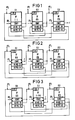
- FIG 1 aus drei Speicherelementen bestehende Warteschlange im Ausgangszustand,
- FIG 2 die Warteschlange von FIG 1 nach Belegung von zwei Speicherelementen und nach Beginn der ersten Weiterleitung,
- FIG 3 die Warteschlange von FIG 2 nach Beginn der zweiten Weiterleitung,
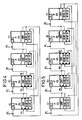
- FIG 4 die Warteschlange von FIG 2 nach Beginn der ersten Weiterleitung und nach der durch die vierte Zwischenspeicherungsanforderung vorgenommenen Erweiterung,
- FIG 5 die Warteschlange von FIG 4 nach Beginn der ersten Weiterleitung und nach der durch die fünfte Zwischenspeicherungsanforderung vorgenommenen Erweiterung und
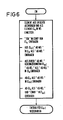
- FIG 6 ein Flußdiagramm zur Erläuterung der notwendigen Adresseneintragsänderungen beim Eingliedern eines neuen Speicherelementes in die bestehende Warteschlange.
- 1 shows a queue consisting of three storage elements in the initial state,
- 2 shows the queue of FIG. 1 after two memory elements have been occupied and after the start of the first forwarding,
- 3 shows the queue of FIG. 2 after the start of the second forwarding,
- 4 shows the queue from FIG. 2 after the start of the first forwarding and after the expansion carried out by the fourth buffering request,
- FIG. 5 shows the queue from FIG. 4 after the start of the first forwarding and after the expansion and by the fifth buffering request
- 6 shows a flowchart to explain the necessary address entry changes when incorporating a new memory element into the existing queue.
FIG 1 zeigt eine aus drei Speicherelmenten EL1 bis EL3 bestehende Warteschlange. Jedes Speicherelement weist neben dem eigentlichen Datenfeld DF für die jeweils zwischenzuspeichernde Information drei Eintragsfelder auf, nämlich ein Adresseneintragsfeld für die Adresse AD-NEL, die auf den Beginn des Datenfeldes im vorangehenden Speicherelement verweist, ein Adresseneintragsfeld für die Adresse AD-VEL, die auf das Adresseneintragsfeld für die Vorwärtsverknüpfung des jeweils nachfolgenden Speicherelementes verweist, und ein Steuereintragsfeld CONTF. Dieses Steuereintragsfeld enthält entweder die Adresse AD-NEL aus dem zugehörigen Adresseneintragsfeld für die Vorwärtsverknüpfung und verweist damit auf das nächste zur Zwischenspeicherung von Informationen bereite Speicherelement, oder es enthält einen Sperreintrag F, der das Ende der belegbaren Warteschlange anzeigt und zur Abweisung einer weiteren Zwischenspeicherungsanforderung führt.1 shows a queue consisting of three storage elements EL1 to EL3. In addition to the actual data field DF, each storage element has three entry fields for the information to be buffered, namely an address entry field for the address AD-NEL, which refers to the beginning of the data field in the preceding storage element, an address entry field for the address AD-VEL, which refers to the Address entry field for the forward link of the subsequent storage element points, and a control entry field CONTF. This control entry field either contains the address AD-NEL from the associated address entry field for the forward link and thus points to the next storage element ready for the temporary storage of information, or it contains a lock entry F which indicates the end of the assignable queue and leads to the rejection of a further buffering request .
In allen, die Darstellung einer Warteschlange treffenden Figuren sind die Ziele dieser Einträge durch entsprechende Verbindungspfeile zwischen den Speicherelementen EL... verdeutlicht, während die in Klammern gesetzten Ziffern in den einzelnen Adresseneintragsfeldern den Nummern, z.B. 1 bis 3 der betreffenden Speicherelemente, z.B. EL1 bis EL3, entsprechen.In all the figures that represent a queue, the destinations of these entries are illustrated by corresponding connecting arrows between the memory elements EL ..., while the numbers in brackets in the individual address entry fields indicate the numbers, e.g. 1 to 3 of the relevant storage elements, e.g. Correspond to EL1 to EL3.
Am Anfang der Datenfelder DF ist jeweils noch ein Eintragsfeld F/B für die Kennzeichnung des "Frei"- bzw. "Belegt"-Zustandes vorgesehen, um die Überprüfung des Belegtzustandes zu vereinfachen.At the beginning of the data fields DF there is also an entry field F / B for the identification of the "free" or "occupied" state in order to simplify the checking of the occupied state.
Der Eintragszeiger EP... ist jeweils auf das Steuereintragsfeld CONTF gerichtet, während der Austragszeiger AP... jeweils auf den Beginn des Datenfeldes DF gerichtet ist, wobei die jeweilige Adresse sich jeweils aus der Adresse für das Speicherelement und einer entsprechenden Distanzadresse ergibt.The entry pointer EP ... is directed in each case to the control entry field CONTF, while the discharge pointer AP ... is directed in each case to the start of the data field DF, the respective address resulting from the address for the storage element and a corresponding distance address.
Da der Eintragszeiger EP1 für die erste Zwischenspeicherungsanforderung auf das Speicherelement EL1 zeigt, ist der Austragszeiger AP1 für die erste Ausspeicherung auf das Speicherelement EL2 gerichtet, und das Speicherelement EL3 führt demzufolge den Sperreintrag F. Folglich wird bei der ersten Zwischenspeicherungsanforderung über den aktuellen Eintragszeiger EP1 das Speicherelemente EL2 belegt, was durch den zusätzlichen Eintrag (E1) im zugehörigen Datenfeld DF angezeigt ist, während bei der zweiten Zwischenspeicherungsanforderung über den Eintragszeiger EP2 das Speicherelement EL3 belegt wird. Würde danach eine dritte Zwischenspeicherungsanforderung eintreffen, bevor das erste belegte Speicherelement EL2 wieder frei ist, dann würde wegen des über den aktuellen Eintragszeiger EP3 erreichbaren Sperreintrags F dieser wirksam und die Anforderung abgewiesen, weil die Warteschlange über kein belegbares Speicherelement mehr verfügt.Since the entry pointer EP1 for the first buffering request points to the storage element EL1, the discharge pointer AP1 for the first withdrawal is directed to the storage element EL2, and the storage element EL3 consequently carries the lock entry F. Consequently, in the first buffering request the current entry pointer EP1 becomes Storage elements EL2 occupy what is indicated by the additional entry (E1) in the associated data field DF, while the storage element EL3 is occupied in the second buffering request by the entry pointer EP2. If a third intermediate storage request would then arrive before the first occupied storage element EL2 is free again, then the lock entry F that can be reached via the current entry pointer EP3 would make this effective and the request would be rejected because the queue no longer has an allocable storage element.
Zwar ist das Speicherelement EL1 noch frei. Dieses muß aber frei bleiben, damit nach einem Leerwerden der Warteschlange der aktuelle Eintragszeiger EP... immer auf das Vorgängerelement zum aktuellen Austragszeiger AP... zeigt, um eine sichere Arbeitsweise der Warteschlange zu gewährleisten. Andernfalls müßte man wie bei den bekannten Anordnungen gesonderte Maßnahmen zur Schaffung einer Überholsperre ergreifen.The memory element EL1 is still free. However, this must remain free so that after the queue becomes empty, the current entry pointer EP ... always points to the predecessor element to the current discharge pointer AP ... in order to ensure that the queue functions reliably. Otherwise, as with the known arrangements, one would have to take separate measures to create an overtaking lock.
Um dennoch über dieses freie Speicherelement, z.B. EL1, früher, d.h. vor Abschluß der dieses Element zur Belegung freigebenden Ausspeicherung, verfügen zu können, erfolgt die Freigabe bereits zu Beginn einer einzuleitenden Ausspeicherung. Dies ist in FIG 2 angedeutet.In order to use this free storage element, e.g. EL1, earlier, i.e. before the completion of the releasing this element for occupancy, the release already takes place at the beginning of a relocation to be initiated. This is indicated in FIG 2.
Beim zuerst belegten Speicherelement EL2 ist die Ausspeicherung eingeleitet, was durch den Pfeil am umrandeten Informationseintrag (E1) angedeutet ist. Der Sperreintrag F ist damit vom Speicherelement EL3 an das zyklisch nachfolgende Speicherelement EL1 weitergegeben worden, so daß eine nachfolgende dritte Zwischenspeicherungsanforderung über den Eintragszeiger EP3 nicht mehr abgewiesen, sondern dem Speicherelement EL1 zugeleitet wird.With the first occupied memory element EL2, the withdrawal is initiated, which is indicated by the arrow on the framed information entry (E1). The lock entry F has thus been forwarded from the storage element EL3 to the cyclically following storage element EL1, so that a subsequent third buffering request via the entry pointer EP3 is no longer rejected, but is instead forwarded to the storage element EL1.
Eine nachfolgende vierte Zwischenspeicherungsanforderung über den Eintragszeiger EP4 würde dagegen wieder abgewiesen. Diese käme gemäß FIG 3 erst zum Zuge, wenn der Austragszeiger AP1 am Ende der ersten Ausspeicherung auf den Austragszeiger AP2 umgestellt und dazu eine neue Ausspeicherungsanforderung eingetroffen ist, der zufolge die zweite Ausspeicherung bereits eingeleitet wäre; usw..A subsequent fourth buffering request via the entry pointer EP4 would be rejected. According to FIG. 3, this would only come into play when the discharge pointer AP1 changed over to the discharge pointer AP2 at the end of the first withdrawal and a new withdrawal request has arrived, according to which the second withdrawal would have already been initiated; etc..
Zur Ansteuerung der Warteschlange sind also lediglich zwei Speicherabschnitte, z.B. Register, zur Bereitstellung des Eintragszeigers EP... und des Austragszeigers AP... erforderlich. Trifft eine Zwischenspeicherungsanforderung ein, kann mit Hilfe des aktuellen Eintragszeigers EP... sofort das zugehörige Speicherelement EL... aufgerufen und anhand des Adresseneintrags im Steuereintragsfeld CONTF auf das zu belegende Speicherelement zugegriffen werden oder die Anforderung wird aufgrund des Sperreintrags F zurückgewiesen. Andererseits erreicht man bei einer Ausspeicherungsanforderung anhand des aktuellen Austragszeigers AP... unmittelbar das Speicherelement, das als erstes zur Ausspeicherung von Informationen ansteht. Ist dieses nicht belegt, was zweckmäßig anhand des Eintragsfeldes F/B zu Beginn des Datenfeldes DF überprüft wird, kann keine Ausspeicherung vorgenommen werden. Dann liegt aber auch in den anderen Speicherelementen EL... der Warteschlange keine Zwischenspeicherung vor. Ist das Datenfeld dagegen belegt, erfolgt vor der eigentlichen Ausspeicherung zweckmäßig die Weitergabe der Sperreintrags, um das bisher gesperrte Speicherelement schneller für eine weitere Zwischenspeicherungsanforderung verfügbar zu machen.To control the queue, therefore, only two memory sections, for example registers, are required to provide the entry pointer EP ... and the discharge pointer AP .... If a buffering request arrives, you can use of the current entry pointer EP ... the associated storage element EL ... is called up immediately and the storage element to be occupied can be accessed using the address entry in the control entry field CONTF or the request is rejected on the basis of the lock entry F. On the other hand, in the case of a withdrawal request, the current discharge pointer AP ... directly leads to the storage element which is the first to be used for the storage of information. If this is not occupied, which is expediently checked using the entry field F / B at the beginning of the data field DF, it cannot be saved. Then there is no intermediate storage in the other storage elements EL ... of the queue. If, on the other hand, the data field is occupied, the lock entry is expediently passed on before the actual storage, in order to make the previously locked storage element available more quickly for a further buffering request.
Die von der Weitergabe des Sperreintrags F betroffenen Speicherelemente EL... und Eintragsfelder sind in FIG 2 und FIG 3 durch Eckdreiecke gekennzeichnet. Zunächst wird im durch den Austragszeiger AP... aufgefundenen Speicherelement als Speicherelement ELn anhand des Adresseneintrags AD-VEL das vorangehende Speicherelement ELn-1 ermittelt und im Steuereintragsfeld CONTF der Sperreintrag F vorgenommen. Danach wird anhand der Adresse AD-VEL in diesem Speicherelement das vorangehende Speicherelement ELn-2 ermittelt und dort die Adresse AD-NEL aus dem dortigen Adresseneintragsfeld in das Steuereintragsfeld CONTF übertragen. Der Sperreintrag in diesem Steuereintragsfeld ist damit gelöscht. Stattdessen wird auf das Element ELn-1 als aufnahmebereites Speicherelement verwiesen.The storage elements EL ... and entry fields affected by the forwarding of the lock entry F are identified by corner triangles in FIG. 2 and FIG. 3. First, in the memory element found by the discharge pointer AP ..., the preceding memory element ELn-1 is determined as the memory element ELn on the basis of the address entry AD-VEL, and the lock entry F is made in the control entry field CONTF. The preceding memory element ELn-2 is then determined on the basis of the address AD-VEL in this memory element and the address AD-NEL is transferred there from the address entry field there into the control entry field CONTF. The lock entry in this tax entry field is now deleted. Instead, reference is made to the element ELn-1 as a recordable storage element.
Der Steuerungsaufwand hierfür ist verhältnismäßig gering und kann bei zweckmäßig programmgesteuerten Einrichtungen in einfacher Weise realisiert werden.The control effort for this is relatively low and can be implemented in a simple manner in the case of appropriately program-controlled devices.
In vielen Anwendungsfällen ist die Länge der Warteschlangen nicht von vornherein absehbar. Ist die Anzahl der vorgegebenen Speicherelemente zu klein gewählt, läuft man Gefahr, daß zuviele Zwischenspeicherungsanforderungen abgewiesen werden müssen. Ist dagegen die Anzahl zu groß, wird unnötige Speicherkapazität gebunden. Es ist daher vorteilhaft, wenn die Warteschlange entsprechend den jeweiligen betrieblichen Erfordernissen hinsichtlich der Anzahl ihrer Speicherelemente erweiterbar ist.In many applications, the length of the queues cannot be predicted from the outset. If the number of predefined storage elements is chosen too small, there is a risk that too many intermediate storage requests must be rejected. On the other hand, if the number is too large, unnecessary storage capacity is tied up. It is therefore advantageous if the queue can be expanded in accordance with the respective operational requirements with regard to the number of its storage elements.
Dieses Erfordernis läßt sich bei dem gegebenen Lösungsprinzip gemäß der Erfindung in einfacher Weise erfüllen. Erforderlich ist dazu lediglich, daß der jeweilige Sperreintrag F nicht mehr zu einer Zurückweisung einer Zwischenspeicherungsanforderung führt, sondern zur Einkettung eines neuen Speicherelementes, das dann die durch die neue Zwischenspeicherungsanforderung bedingte Zwischenspeicherung ermöglicht.This requirement can be met in a simple manner with the given solution principle according to the invention. All that is required is that the respective lock entry F no longer leads to a rejection of a buffering request, but to the chaining of a new storage element, which then enables the buffering caused by the new buffering request.
Dieser Fall ist ausgehend von der Warteschlange gemäß FIG 2 in FIG 4 dargestellt. Die auf den Eintragszeiger EP4 bezogene Zwischenspeicherungsanforderung führt in diesem Falle nicht zu einer Zurückweisung der Zwischenspeicherungsanforderung, sondern aufgrund des Eintrags EIN im angesteuerten Steuereintragsfeld zum Einketten eines vierten Speicherelementes EL4 in die Warteschlange. Bevor dieses Speicherelement EL4 zur Aufnahme der neuen Information (E4) bereitgestellt werden kann, müssen jedoch die Einträge in den jeweils betroffenen Speicherelmenten ergänzt bzw. geändert werden.This case is shown in FIG. 4 starting from the queue in FIG. 2. In this case, the buffering request relating to the entry pointer EP4 does not lead to a rejection of the buffering request, but rather to chain a fourth storage element EL4 into the queue on the basis of the entry ON in the controlled control entry field. Before this storage element EL4 can be made available for receiving the new information (E4), however, the entries in the storage elements concerned must be supplemented or changed.
Betroffen sind jeweils drei Speicherelemente, nämlich das neu einzukettende Speicherelement EL4, das die Einkettung auslösende Speicherelement EL1 und das diesem bisher nachfolgende Speicherelement EL2. Die betroffenen Eintragsfelder dieser Speicherelemente EL4, EL1 und EL2 sind wiederum mit Eckdreiecken gekennzeichnet.Three memory elements are concerned in each case, namely the memory element EL4 to be newly chained, the memory element EL1 which triggers the chaining and the memory element EL2 which has hitherto followed this. The affected entry fields of these memory elements EL4, EL1 and EL2 are again identified by corner triangles.
Der Steuerungsablauf für die damit verbundene Einkettungroutine ergibt sich aus FIG 6.The control sequence for the associated chaining routine results from FIG. 6.
Danach wird zunächst im Speicher ein verfügbares Speicherelement ELn ausgewählt und in dessen Steuereintragsfeld CONTF der Einkettungshinweis "EIN" eingetragen. In dem durch den aktuellen Eintragszeiger, z.B. EP4, gekennzeichneten Speicherelement, z.B. EL1 als ELn-1, wird dann das Adresseneintragsfeld für die Vorwärtsadresse AD-NEL gelesen und in das entsprechende Eintragsfeld des neuen Speicherelementes ELn = EL4 eingetragen. Weiterhin wird das durch diesen Eintrag gekennzeichnete bisherige Nachfolgeelement EL2 als Speicherelement ELn+1 angesteuert, die dortige Rückwärtsadresse AD-VEL gelesen und in das entsprechende Eintragsfeld des neuen Speicherelementes EL4 = ELn übertragen, während in das gelesene Adresseneintragsfeld des Speicherelementes EL2 als ELn+1 die Adresse des neuen Speicherelementes EL4 als AD-VEL eingetragen wird. Anschließend wird noch im durch den Eintragszeiger EP4 gekennzeichneten Speicherelement EL1 als Speicherelement ELn-1 die Hinweisadresse auf das neu eingekettete Speicherelement EL4 in das Eintragsfeld für die Vorwärtsadresse AD-NEL und in das Steuereintragsfeld CONTF eingetragen. Das neue Speicherelement EL4 ist damit in die bestehende Kette eingegliedert, wobei durch die Übernahme des Sperreintrags in dieses Element das bisher sperrende Speicherelement EL1 die Entgegennahme der mit dem Eintragszeiger EP4 verbundenen vierten Zwischenspeicherungsanforderung bei Wiederholung zuläßt.Then an available storage element ELn is first selected in the memory and the chaining notice "ON" is entered in its control entry field CONTF. In the by the current entry pointer, e.g. EP4, labeled memory element, e.g. EL1 as ELn-1, the address entry field for the forward address AD-NEL is then read and entered in the corresponding entry field of the new memory element ELn = EL4. Furthermore, the previous successor element EL2 identified by this entry is actuated as memory
FIG 5 zeigt schließlich die Entwicklung der Warteschlange von FIG 4, wenn nach dem Einketten des Speicherelementes EL4 und dessen Belegung eine weitere auf den Eintragszeiger EP5 bezogene fünfte Zwischenspeicherungsanforderung eintrifft, bevor der durch den Austragszeiger AP1 ausgelöste Ausspeichervorgang abgeschlossen und auf den neuen Austragszeiger AP2 umgesteuert ist. In diesem Falle wird wie bei FIG 4 erst ein weiteres Spei cherelement EL5 eingekettet, das dann die auf den Eintragszeiger EP5 bezogene Zwischenspeicherungsanforderung bedienen kann.FIG. 5 finally shows the development of the queue from FIG. 4 if, after the storage element EL4 has been linked in and occupied, a further fifth buffer request relating to the entry pointer EP5 arrives before the withdrawal process triggered by the discharge pointer AP1 is completed and switched to the new discharge pointer AP2 . In this case, as in FIG chained element EL5, which can then serve the buffering request related to the entry pointer EP5.
In gleicher Weise können frei werdende Speicherelemente auch wieder ausgekettet werden. Ausgangspunkt hierfür ist eine Überprüfung des jeweils nächstfolgenden Speicherelementes, auf das der Adresseneintrag AD-NEL für die Vorwärtsverknüpfung hinweist und auf das der Austragszeiger AP... nach Freigabe eines Speicherelementes einzustellen ist. Ist nämlich dieses Speicherelement nicht mehr belegt, dann sind voraussetzungsgemäß auch alle übrigen Speicherelemente der Warteschlange nicht belegt. Das freigewordene Speicherelement kann daher ausgekettet werden, wenn die Anzahl der Speicherelemente in der Warteschlange größer ist als die erforderliche Mindestanzahl von zwei Speicherelementen. Dies läßt sich in einfacher Weise daran erkennen, ob die beiden Adresseneinträge im frei gewordenen oder auch im nachfolgenden Speicherelement übereinstimmen oder nicht. Nur im letzten Falle kann freigegeben werden.In the same way, memory elements that become free can also be chained out again. The starting point for this is a check of the next successive memory element to which the address entry AD-NEL indicates for the forward link and to which the discharge pointer AP ... is to be set after a memory element has been released. If this storage element is no longer occupied, then all other storage elements of the queue are not occupied as required. The memory element that has become free can therefore be chained out if the number of memory elements in the queue is greater than the required minimum number of two memory elements. This can be recognized in a simple manner by whether the two address entries in the memory element that has become free or also in the subsequent memory element match or not. Only in the latter case can approval be given.
Um bei der Auskettung eines Speicherelementes die Adressenverknüpfung innerhalb der Kette aufrechtzuerhalten, muß im auf das jeweils frei gewordene Speicherelement n vorangehenden Speicherelement n+1 der Adresseneintrag AD-VEL für die Rückwärtsverknüpfung auf den des frei werdenden Speicherelementes n und im durch diesen Adresseneintrag bestimmten nachfolgenden Speicherelement n-1 der Adresseneintrag AD-NEL für die Vorwärtsverknüpfung auf den des frei werdenden Speicherelementes n umgestellt werden. Nach der Auskettung eines Speicherelementes wird der Austragszeiger auf das nächstfolgende Speicherelement umgestellt. Der Auskettungsvorgang kann dann gegebenenfalls wiederholt werden, bis schließlich keine Auskettung mehr möglich ist.In order to maintain the address link within the chain when chaining out a memory element, the address entry AD-VEL for the reverse link to the memory element n becoming free and in the subsequent memory element determined by this address entry must be present in the memory element n + 1 preceding the respectively released memory element n + 1 n-1 the address entry AD-NEL for the forward link to that of the memory element n which is to be freed. After a storage element has been decoupled, the discharge pointer is switched to the next storage element. The chaining-out process can then be repeated, if necessary, until finally chaining out is no longer possible.
Die Einkettung eines neuen Speicherelementes und gegebenenfalls die Auskettung eines Speicherelementes erfordern zwar einen zusätzlichen Steuerungsaufwand in Form einer zusätzlichen Einkettungsroutine bzw. zusätzliche Steuervorgänge. Dieser Aufwand fällt aber gegenüber den durch die dynamische Anpassungsmöglichkeit gegebenen Vorteilen nicht weiter ins Gewicht, da in vielen Fällen die notwendige Reaktion auf eine abgewiesene Zwischenspeicherungsanforderung wesentlich größere Belastungen und Zeitverluste verursacht.The chaining of a new memory element and possibly the chaining of a memory element do require additional control effort in the form of an additional chaining routine or additional control processes. This effort is of no further importance compared to the advantages provided by the dynamic adaptation option, since in many cases the necessary reaction to a rejected buffering request causes significantly greater loads and wasted time.
Claims (5)
dadurch gekennzeichnet,
- daß die Warteschlange aus frei verfügbaren Speicherelementen (z.B. EL1 bis EL3) einer gemeinsamen Speichereinheit gebildet ist, die durch einen auf das jeweils nächste Speicherelement verweisenden Adresseneintrag (AD-NEL) und durch einen aus das jeweils vorhergehende Speicherelement verweisenden Adresseneintrag (AD-VEL) zu einer Ringkette verknüpft sind,
- daß jedes Speicherelement (EL...) neben den beiden Adresseneinträgen (AD-NEL und AD-VEL) ein weiteres Steuereintragsfeld (CONTF) aufweist, das abhängig vom Belegungszustand der Warteschlange entweder entsprechend dem auf das nächste Speicherelement verweisenden Adresseneintrag (AD-NEL) ebenfalls auf das nächste Speicherelement verweist, wenn dieses zur Zwischenspeicherung bereit ist, oder aber einen die Zwischenspeicherung von weiteren Informationen verhindernden Sperreintrag (F) enthält,
- daß ein die Einspeicherung von Informationen steuernder Eintragszeiger (EP...) immer auf das Steuereintragsfeld (CONTF) des Speicherelementes (z.B. EL1) zeigt, das dem die einzuspeichernde Information aufnehmenden Speicherelement (z.B. EL2) vorangeht, während ein die Weiterleitung der Informationen steuernder Austragszeiger (AP...) immer auf den Beginn des die zwischengespeicherte Information beinhaltenden Datenfeldes (DF) eines Speicherelementes ( z.B. EL2) zeigt, dessen Information als erste von allen gespeicherten weiterzuleiten ist, wobei der Eintragszeiger (EP...) nach jedem Eintrag einer Information und der Austragszeiger (AP...) nach jeder Weiterleitung einer Information durch die Warteschlangensteuerung auf das durch den in Vorwärtsrichtung der Kette verweisenden Adresseneintrag (AD-NEL) bestimmte Speicherelement einstellbar ist.1. queue, consisting of several storage elements (eg EL1 - EL3) for the temporary storage of information to be forwarded to a recipient and a controller for the storage and storage of the information, the information being forwarded in the order of its intermediate storage (FIFO principle),
characterized,
- That the queue is formed from freely available memory elements (for example EL1 to EL3) of a common memory unit, which is formed by an address entry (AD-NEL) referring to the next memory element and by an address entry (AD-VEL) referring to the previous memory element. are linked to form a ring chain,
- That each storage element (EL ...) in addition to the two address entries (AD-NEL and AD-VEL) has a further control entry field (CONTF) which, depending on the occupancy of the queue, either according to the address entry referring to the next storage element (AD-NEL ) also refers to the next storage element if it is ready for temporary storage or contains a lock entry (F) which prevents further information from being stored temporarily,
- That an entry pointer (EP ...) controlling the storage of information always points to the control entry field (CONTF) of the storage element (for example EL1), which precedes the storage element (for example EL2) which receives the information to be stored, while one which controls the forwarding of the information Discharge pointer (AP ...) always points to the beginning of the data field (DF) containing the temporarily stored information of a storage element (e.g. EL2), the information of which must be passed on first from all stored elements, with the entry pointer (EP ...) after each entry information and the discharge pointer (AP ...) after each forwarding of information by the queue controller to the storage element determined by the address entry pointing in the forward direction of the chain (AD-NEL) is adjustable.
dadurch gekennzeichnet, daß zu Beginn eines Datenfeldes (DF) im jeweiligen Speicherelement (z.B. E1) ein Eintragsfeld (F/B) zur Kennzeichnung des Frei- oder Belegtzustandes des Datenfeldes (DF) und damit des Speicherelementes (EL1) vorgesehen ist.2. Queue according to claim 1,
characterized in that an entry field (F / B) is provided at the beginning of a data field (DF) in the respective memory element (for example E1) to identify the free or occupied state of the data field (DF) and thus of the memory element (EL1).
dadurch gekennzeichnet, daß nach Ansteuerung eines durch den Austragszeiger (z.B. AP1) gekennzeichneten Speicherelementes (z.B. EL2) durch die Warteschlangensteuerung zwecks Weiterleitung der zwischengespeicherten Information noch vor Beginn der eigentlichen Weiterleitung der Information aus dem Datenfeld (DF) ein im Steuereintragsfeld (CONTF) des dem durch den Austragszeiger (AP1) gekennzeichneten Speicherelement (EL2) in der Kette vorangehenden vorletzten Speicherelementes (EL3) enthaltene Sperreintrag (F) in das Steuereintragsfeld (CONTF) des letzten Speicherelementes (EL1) übertragen wird, so daß noch vor der Freigabe des durch den Austragszeiger (AP1) gekennzeichneten Speicherelementes (EL2) nach Weiterleitung der dort zwischengespeicherten Information das letzte Speicherelement (EL1) der Kette zur Zwischenspeicherung einer weiteren Information zur Verfügung steht.3. Queue according to claim 1 or 2,
characterized in that after actuation of a storage element (for example AP1) identified by the discharge pointer (for example EL2) by the queue control for the purpose of forwarding the temporarily stored information even before the actual forwarding of the information from the data field (DF) a in the control entry field (CONTF) of the by the discharge pointer (AP1) marked storage element (EL2) in the chain of the penultimate storage element (EL3) preceding the lock entry (F) is transferred to the control entry field (CONTF) of the last storage element (EL1), so that even before the release by the discharge pointer (AP1) marked memory element (EL2) after forwarding the information temporarily stored there, the last memory element (EL1) of the chain is available for intermediate storage of further information.
dadurch gekennzeichnet, daß die Warteschlange jeweils bei Ansteuerung eines Steuereintragsfeldes (CONTF) mit Sperreintrag (F) durch die Warteschlangensteuerung um ein weiteres verfügbares Element (z.B. EL4 oder EL5) aus der gemeinsamen Speichereinheit erweiterbar ist, wobei das neue Speicherelement (z.B. EL4) jeweils als nächstfolgendes nach dem den Sperreintrag liefernden Speicherelement (z.B. E1) in die Kette eingefügt und der Sperreintrag an das Steuereintragsfeld (CONTF) des neuen Speicherelementes (z.B. EL4) übernommen wird, sowie die Adresseneinträge (AD-NEL und AD-VEL) anhand der vorhandenen Adressenverknüpfungen zur Aufrechterhaltung der Ringstruktur geändert werden.4. Queue according to one of claims 1 to 3,
characterized in that the queue can be expanded by a further available element (for example EL4 or EL5) from the common memory unit each time a control entry field (CONTF) with lock entry (F) is activated by the queue control, the new one Memory element (e.g. EL4) is inserted into the chain as the next one after the memory element providing the lock entry (e.g. E1) and the lock entry is transferred to the control entry field (CONTF) of the new memory element (e.g. EL4), as well as the address entries (AD-NEL and AD -VEL) can be changed based on the existing address links to maintain the ring structure.
dadurch gekennzeichnet, daß mit dem auf das nächstfolgende Speicherelement (z.B. EL3) nach Weiterleitung einer Information eingestellten Austragszeiger (AP2) der Belegungszustand dieses nächstfolgenden Speicherelementes überprüft wird, daß bei unbelegt gefundenem Speicherelement auch die beiden Adresseneinträge (AD-NEL, AD-VEL) dieses oder des frei gewordenen Speicherelementes (EL3 bzw. EL2) überprüft werden, daß bei voneinander abweichenden Adresseneinträgen das freigegebene Speicherelement (EL2) aus der Warteschlange ausgekettet wird, indem der Adresseneintrag (AD-VEL) für die Rückwärtsverknüpfung des auszukettenden Speicherelements (EL2) als solcher beim Überprüften nächstfolgenden Speicherelement (EL3) eingetragen wird, und daß anschließend das durch diesen Adresseneintrag gekennzeichnete nächstvorangehende Speicherelement (EL1) aufgesucht und dort der Adresseneintrag (AD-NEL) für die Vorwärtsverknüpfung aus dem auszukettenden Speicherglied (E2) als solcher eingetragen wird.5. queue according to claim 4,
characterized in that the occupancy state of this next memory element is checked with the discharge pointer (AP2) set to the next memory element (for example EL3) after forwarding information , that if the memory element is found unoccupied, the two address entries (AD-NEL, AD-VEL) also contain this or the memory element (EL3 or EL2) that has become free are checked that, in the case of differing address entries, the released memory element (EL2) is decoupled from the queue by the address entry (AD-VEL) for the reverse linkage of the memory element (EL2) to be decoupled as such when checking the next following memory element (EL3) is entered, and that the next previous memory element (EL1) identified by this address entry is then searched and there the address entry (AD-NEL) for the forward link from the memory element (E2) to be chained out as such is carried.
Priority Applications (4)
| Application Number | Priority Date | Filing Date | Title |
|---|---|---|---|
| ES198888116010T ES2041757T3 (en) | 1988-09-28 | 1988-09-28 | WAITING TAIL, CONSTITUTED BY SEVERAL MEMORY ELEMENTS. |
| AT88116010T ATE92657T1 (en) | 1988-09-28 | 1988-09-28 | QUEUE CONSISTING OF SEVERAL STORAGE ELEMENTS. |
| DE8888116010T DE3882992D1 (en) | 1988-09-28 | 1988-09-28 | QUEUE, MULTIPLE STORAGE ELEMENTS. |
| EP19880116010 EP0360899B1 (en) | 1988-09-28 | 1988-09-28 | Queue comprising a plurality of memory elements |
Applications Claiming Priority (1)
| Application Number | Priority Date | Filing Date | Title |
|---|---|---|---|
| EP19880116010 EP0360899B1 (en) | 1988-09-28 | 1988-09-28 | Queue comprising a plurality of memory elements |
Publications (2)
| Publication Number | Publication Date |
|---|---|
| EP0360899A1 true EP0360899A1 (en) | 1990-04-04 |
| EP0360899B1 EP0360899B1 (en) | 1993-08-04 |
Family
ID=8199384
Family Applications (1)
| Application Number | Title | Priority Date | Filing Date |
|---|---|---|---|
| EP19880116010 Expired - Lifetime EP0360899B1 (en) | 1988-09-28 | 1988-09-28 | Queue comprising a plurality of memory elements |
Country Status (4)
| Country | Link |
|---|---|
| EP (1) | EP0360899B1 (en) |
| AT (1) | ATE92657T1 (en) |
| DE (1) | DE3882992D1 (en) |
| ES (1) | ES2041757T3 (en) |
Cited By (3)
| Publication number | Priority date | Publication date | Assignee | Title |
|---|---|---|---|---|
| EP0489248A2 (en) * | 1990-12-01 | 1992-06-10 | GRUNDIG E.M.V. Elektro-Mechanische Versuchsanstalt Max Grundig GmbH & Co. KG | Address control for a first-in first-out memory |
| EP0693725A2 (en) | 1994-07-11 | 1996-01-24 | Siemens Nixdorf Informationssysteme AG | Data processing apparatus including a device for handling interrupt requests and process calls in real time |
| EP0760501A1 (en) * | 1995-09-04 | 1997-03-05 | Hewlett-Packard Company | Data handling system with circular queue formed in paged memory |
-
1988
- 1988-09-28 DE DE8888116010T patent/DE3882992D1/en not_active Expired - Fee Related
- 1988-09-28 EP EP19880116010 patent/EP0360899B1/en not_active Expired - Lifetime
- 1988-09-28 ES ES198888116010T patent/ES2041757T3/en not_active Expired - Lifetime
- 1988-09-28 AT AT88116010T patent/ATE92657T1/en not_active IP Right Cessation
Non-Patent Citations (1)
| Title |
|---|
| IBM TECHNICAL DISCLOSURE BULLETIN, Band 22, Nr. 10, März 1980, Seiten 4749-4752, New York, US; A.M. SHANKLAND et al.: "Storage of documents in a direct-access storage device" * |
Cited By (5)
| Publication number | Priority date | Publication date | Assignee | Title |
|---|---|---|---|---|
| EP0489248A2 (en) * | 1990-12-01 | 1992-06-10 | GRUNDIG E.M.V. Elektro-Mechanische Versuchsanstalt Max Grundig GmbH & Co. KG | Address control for a first-in first-out memory |
| EP0489248A3 (en) * | 1990-12-01 | 1993-08-25 | Grundig E.M.V. Elektro-Mechanische Versuchsanstalt Max Grundig Hollaend. Stiftung & Co. Kg. | Address control for a first-in first-out memory |
| EP0693725A2 (en) | 1994-07-11 | 1996-01-24 | Siemens Nixdorf Informationssysteme AG | Data processing apparatus including a device for handling interrupt requests and process calls in real time |
| EP0760501A1 (en) * | 1995-09-04 | 1997-03-05 | Hewlett-Packard Company | Data handling system with circular queue formed in paged memory |
| US5873089A (en) * | 1995-09-04 | 1999-02-16 | Hewlett-Packard Company | Data handling system with circular queue formed in paged memory |
Also Published As
| Publication number | Publication date |
|---|---|
| ES2041757T3 (en) | 1993-12-01 |
| DE3882992D1 (en) | 1993-09-09 |
| EP0360899B1 (en) | 1993-08-04 |
| ATE92657T1 (en) | 1993-08-15 |
Similar Documents
| Publication | Publication Date | Title |
|---|---|---|
| DE2162806C2 (en) | Memory control unit for simplified buffering of requests from the input / output channels | |
| DE4019135C2 (en) | RAM-based serial memory with parallel prefetch and method for storing data items in a serial memory device | |
| DE3126363C2 (en) | Direct memory access control circuit and method of controlling the transmission of data words | |
| DE1499182C3 (en) | Data storage system | |
| DE2331589A1 (en) | DATA PROCESSING ARRANGEMENT | |
| CH638913A5 (en) | DEVICE IN TEXT PROCESSING PLANTS FOR SELECTING DATA QUALIFIED DIFFERENT LENGTH. | |
| EP0329005B1 (en) | Method for establishing virtual circuits via switches of a multistage switching arrangement | |
| DE3148099C2 (en) | Arrangement for recognizing a digital sequence | |
| CH631386A5 (en) | TEXT PROCESSING MACHINE. | |
| CH634938A5 (en) | DEVICE FOR FORWARDING MEMORY ACCESS REQUIREMENTS. | |
| DE2720864A1 (en) | PROCEDURE AND ARRANGEMENT FOR STORING A NUMBER OF DATABLES OF UNDEFINITE LENGTH WITHOUT LEAPS | |
| DE3048414A1 (en) | "CIRCUIT ARRANGEMENT FOR A DATA PROCESSING SYSTEM" | |
| DE1524181B2 (en) | SELECTION DEVICE FOR INPUT AND OUTPUT DEVICES OF A DATA PROCESSING SYSTEM | |
| EP0360899B1 (en) | Queue comprising a plurality of memory elements | |
| DE2610428C3 (en) | Arrangement for controlling the intermediate storage of data to be transmitted between two functional units in a buffer memory | |
| DE3009121C2 (en) | Microprogram controller | |
| DE3149678C2 (en) | Arrangement for the intermediate storage of information to be transmitted between two functional units in both directions in a buffer memory | |
| DE2801707C2 (en) | Device for text editing and processing, such as typewriter, data entry station or the like. | |
| EP0360900B1 (en) | Method for treating work calls to one of the processes from the single processes of a data processing system | |
| DE2911147C2 (en) | ||
| DE3248393C2 (en) | ||
| DE4342521C1 (en) | Compressed data expansion method | |
| DE2816838C2 (en) | Method and priority control unit for assigning priorities | |
| EP0164578B1 (en) | Storage method for grouped communications switching data | |
| DE1774466B2 (en) | DATA PROCESSING SYSTEM |
Legal Events
| Date | Code | Title | Description |
|---|---|---|---|
| PUAI | Public reference made under article 153(3) epc to a published international application that has entered the european phase |
Free format text: ORIGINAL CODE: 0009012 |
|
| AK | Designated contracting states |
Kind code of ref document: A1 Designated state(s): AT BE CH DE ES FR GB IT LI NL SE |
|
| 17P | Request for examination filed |
Effective date: 19900425 |
|
| RAP1 | Party data changed (applicant data changed or rights of an application transferred) |
Owner name: SIEMENS NIXDORF INFORMATIONSSYSTEME AG |
|
| 17Q | First examination report despatched |
Effective date: 19921030 |
|
| GRAA | (expected) grant |
Free format text: ORIGINAL CODE: 0009210 |
|
| AK | Designated contracting states |
Kind code of ref document: B1 Designated state(s): AT BE CH DE ES FR GB IT LI NL SE |
|
| REF | Corresponds to: |
Ref document number: 92657 Country of ref document: AT Date of ref document: 19930815 Kind code of ref document: T |
|
| PGFP | Annual fee paid to national office [announced via postgrant information from national office to epo] |
Ref country code: ES Payment date: 19930826 Year of fee payment: 6 |
|
| PGFP | Annual fee paid to national office [announced via postgrant information from national office to epo] |
Ref country code: AT Payment date: 19930827 Year of fee payment: 6 |
|
| REF | Corresponds to: |
Ref document number: 3882992 Country of ref document: DE Date of ref document: 19930909 |
|
| PGFP | Annual fee paid to national office [announced via postgrant information from national office to epo] |
Ref country code: SE Payment date: 19930914 Year of fee payment: 6 |
|
| PGFP | Annual fee paid to national office [announced via postgrant information from national office to epo] |
Ref country code: NL Payment date: 19930930 Year of fee payment: 6 |
|
| ITF | It: translation for a ep patent filed |
Owner name: STUDIO JAUMANN |
|
| REG | Reference to a national code |
Ref country code: CH Ref legal event code: PFA Free format text: SIEMENS NIXDORF INFORMATIONSSYSTEME AKTIENGESELLSCHAFT |
|
| GBT | Gb: translation of ep patent filed (gb section 77(6)(a)/1977) |
Effective date: 19931014 |
|
| RAP4 | Party data changed (patent owner data changed or rights of a patent transferred) |
Owner name: SIEMENS NIXDORF INFORMATIONSSYSTEME AG |
|
| REG | Reference to a national code |
Ref country code: ES Ref legal event code: FG2A Ref document number: 2041757 Country of ref document: ES Kind code of ref document: T3 |
|
| ET | Fr: translation filed | ||
| PGFP | Annual fee paid to national office [announced via postgrant information from national office to epo] |
Ref country code: CH Payment date: 19931215 Year of fee payment: 6 |
|
| PLBE | No opposition filed within time limit |
Free format text: ORIGINAL CODE: 0009261 |
|
| STAA | Information on the status of an ep patent application or granted ep patent |
Free format text: STATUS: NO OPPOSITION FILED WITHIN TIME LIMIT |
|
| 26N | No opposition filed | ||
| PG25 | Lapsed in a contracting state [announced via postgrant information from national office to epo] |
Ref country code: AT Effective date: 19940928 |
|
| PG25 | Lapsed in a contracting state [announced via postgrant information from national office to epo] |
Ref country code: SE Effective date: 19940929 Ref country code: ES Free format text: LAPSE BECAUSE OF EXPIRATION OF PROTECTION Effective date: 19940929 |
|
| PG25 | Lapsed in a contracting state [announced via postgrant information from national office to epo] |
Ref country code: LI Effective date: 19940930 Ref country code: CH Effective date: 19940930 |
|
| EAL | Se: european patent in force in sweden |
Ref document number: 88116010.5 |
|
| PG25 | Lapsed in a contracting state [announced via postgrant information from national office to epo] |
Ref country code: NL Effective date: 19950401 |
|
| NLV4 | Nl: lapsed or anulled due to non-payment of the annual fee | ||
| REG | Reference to a national code |
Ref country code: CH Ref legal event code: PL |
|
| EUG | Se: european patent has lapsed |
Ref document number: 88116010.5 |
|
| PGFP | Annual fee paid to national office [announced via postgrant information from national office to epo] |
Ref country code: GB Payment date: 19970826 Year of fee payment: 10 |
|
| PGFP | Annual fee paid to national office [announced via postgrant information from national office to epo] |
Ref country code: BE Payment date: 19970912 Year of fee payment: 10 |
|
| PGFP | Annual fee paid to national office [announced via postgrant information from national office to epo] |
Ref country code: FR Payment date: 19970924 Year of fee payment: 10 |
|
| PG25 | Lapsed in a contracting state [announced via postgrant information from national office to epo] |
Ref country code: GB Free format text: LAPSE BECAUSE OF NON-PAYMENT OF DUE FEES Effective date: 19980928 |
|
| PG25 | Lapsed in a contracting state [announced via postgrant information from national office to epo] |
Ref country code: BE Free format text: LAPSE BECAUSE OF NON-PAYMENT OF DUE FEES Effective date: 19980930 |
|
| PGFP | Annual fee paid to national office [announced via postgrant information from national office to epo] |
Ref country code: DE Payment date: 19981117 Year of fee payment: 11 |
|
| BERE | Be: lapsed |
Owner name: SIEMENS NIXDORF INFORMATIONSSYSTEME A.G. Effective date: 19980930 |
|
| GBPC | Gb: european patent ceased through non-payment of renewal fee |
Effective date: 19980928 |
|
| PG25 | Lapsed in a contracting state [announced via postgrant information from national office to epo] |
Ref country code: FR Free format text: LAPSE BECAUSE OF NON-PAYMENT OF DUE FEES Effective date: 19990531 |
|
| REG | Reference to a national code |
Ref country code: FR Ref legal event code: ST |
|
| PG25 | Lapsed in a contracting state [announced via postgrant information from national office to epo] |
Ref country code: DE Free format text: LAPSE BECAUSE OF NON-PAYMENT OF DUE FEES Effective date: 20000701 |
|
| REG | Reference to a national code |
Ref country code: ES Ref legal event code: FD2A Effective date: 20010201 |
|
| PG25 | Lapsed in a contracting state [announced via postgrant information from national office to epo] |
Ref country code: IT Free format text: LAPSE BECAUSE OF NON-PAYMENT OF DUE FEES;WARNING: LAPSES OF ITALIAN PATENTS WITH EFFECTIVE DATE BEFORE 2007 MAY HAVE OCCURRED AT ANY TIME BEFORE 2007. THE CORRECT EFFECTIVE DATE MAY BE DIFFERENT FROM THE ONE RECORDED. Effective date: 20050928 |