EP0358911B1 - Image recognition audience measurement system - Google Patents
Image recognition audience measurement system Download PDFInfo
- Publication number
- EP0358911B1 EP0358911B1 EP89113972A EP89113972A EP0358911B1 EP 0358911 B1 EP0358911 B1 EP 0358911B1 EP 89113972 A EP89113972 A EP 89113972A EP 89113972 A EP89113972 A EP 89113972A EP 0358911 B1 EP0358911 B1 EP 0358911B1
- Authority
- EP
- European Patent Office
- Prior art keywords
- image
- recognition system
- recited
- image recognition
- signal
- Prior art date
- Legal status (The legal status is an assumption and is not a legal conclusion. Google has not performed a legal analysis and makes no representation as to the accuracy of the status listed.)
- Expired - Lifetime
Links
Images


Classifications
-
- H—ELECTRICITY
- H04—ELECTRIC COMMUNICATION TECHNIQUE
- H04H—BROADCAST COMMUNICATION
- H04H60/00—Arrangements for broadcast applications with a direct linking to broadcast information or broadcast space-time; Broadcast-related systems
- H04H60/35—Arrangements for identifying or recognising characteristics with a direct linkage to broadcast information or to broadcast space-time, e.g. for identifying broadcast stations or for identifying users
- H04H60/45—Arrangements for identifying or recognising characteristics with a direct linkage to broadcast information or to broadcast space-time, e.g. for identifying broadcast stations or for identifying users for identifying users
-
- G—PHYSICS
- G06—COMPUTING; CALCULATING OR COUNTING
- G06V—IMAGE OR VIDEO RECOGNITION OR UNDERSTANDING
- G06V40/00—Recognition of biometric, human-related or animal-related patterns in image or video data
- G06V40/10—Human or animal bodies, e.g. vehicle occupants or pedestrians; Body parts, e.g. hands
- G06V40/16—Human faces, e.g. facial parts, sketches or expressions
- G06V40/161—Detection; Localisation; Normalisation
- G06V40/166—Detection; Localisation; Normalisation using acquisition arrangements
-
- G—PHYSICS
- G06—COMPUTING; CALCULATING OR COUNTING
- G06V—IMAGE OR VIDEO RECOGNITION OR UNDERSTANDING
- G06V20/00—Scenes; Scene-specific elements
- G06V20/50—Context or environment of the image
- G06V20/52—Surveillance or monitoring of activities, e.g. for recognising suspicious objects
- G06V20/53—Recognition of crowd images, e.g. recognition of crowd congestion
-
- H—ELECTRICITY
- H04—ELECTRIC COMMUNICATION TECHNIQUE
- H04H—BROADCAST COMMUNICATION
- H04H60/00—Arrangements for broadcast applications with a direct linking to broadcast information or broadcast space-time; Broadcast-related systems
- H04H60/56—Arrangements characterised by components specially adapted for monitoring, identification or recognition covered by groups H04H60/29-H04H60/54
- H04H60/59—Arrangements characterised by components specially adapted for monitoring, identification or recognition covered by groups H04H60/29-H04H60/54 of video
-
- H—ELECTRICITY
- H04—ELECTRIC COMMUNICATION TECHNIQUE
- H04N—PICTORIAL COMMUNICATION, e.g. TELEVISION
- H04N21/00—Selective content distribution, e.g. interactive television or video on demand [VOD]
- H04N21/40—Client devices specifically adapted for the reception of or interaction with content, e.g. set-top-box [STB]; Operations thereof
- H04N21/41—Structure of client; Structure of client peripherals
- H04N21/422—Input-only peripherals, i.e. input devices connected to specially adapted client devices, e.g. global positioning system [GPS]
- H04N21/42201—Input-only peripherals, i.e. input devices connected to specially adapted client devices, e.g. global positioning system [GPS] biosensors, e.g. heat sensor for presence detection, EEG sensors or any limb activity sensors worn by the user
-
- H—ELECTRICITY
- H04—ELECTRIC COMMUNICATION TECHNIQUE
- H04N—PICTORIAL COMMUNICATION, e.g. TELEVISION
- H04N7/00—Television systems
- H04N7/16—Analogue secrecy systems; Analogue subscription systems
- H04N7/173—Analogue secrecy systems; Analogue subscription systems with two-way working, e.g. subscriber sending a programme selection signal
- H04N7/17309—Transmission or handling of upstream communications
-
- H—ELECTRICITY
- H04—ELECTRIC COMMUNICATION TECHNIQUE
- H04N—PICTORIAL COMMUNICATION, e.g. TELEVISION
- H04N19/00—Methods or arrangements for coding, decoding, compressing or decompressing digital video signals
- H04N19/20—Methods or arrangements for coding, decoding, compressing or decompressing digital video signals using video object coding
Definitions
- the present invention relates generally to image recognition systems for use with television audience measurement and marketing data collection systems, and more particularly to image recognition systems for identifying predetermined individual members of a viewing audience.
- United States Patent No. 3,056,135 describes a method and apparatus for automatically determining the listening habits of wave signal receiver users.
- the method disclosed in this patent provides a record of the number and types of persons using a wave signal receiver by monitoring the operational conditions of the receiver and utilizing both strategically placed switches for counting the number of persons entering, leaving and within a particular area and a photographic recorder for periodically recording the composition of the audience.
- a mailable magazine provides a record of both the audience composition and the receiver operation information for manual processing by a survey organization.
- acquiring data is slow and further many viewing audience members object to being identified from the photographic record.
- United States Patent No. 4,644,509 discloses an ultrasonic, pulse-echo method and apparatus for determining the number of persons in the audience and the composition of the audience of a radio receiver and/or a television receiver.
- First and second reflected ultrasonic wave maps of the monitored area are collected, first without people and second with people who may be present in the monitored area.
- the first collected background defining map is subtracted from the second collected map to obtain a resulting map.
- the resulting map is processed to identify clusters having a minimum intensity.
- a cluster size of the thus identified clusters is utilized to identify clusters corresponding to people in an audience.
- United States Patent No. 4,769,697 describes a system employing sensing of individual heat-radiating bodies in a viewing area.
- the heat-radiating bodies are located by scanning and sorted out by pattern recognition and comparison in an attempt to identify individual human beings yet in doing so the system depends on guesses, no actual identification being obtained.
- Japanese Patent Abstract 59-208 699 discloses a system to identity a person sitting in the driver's seat of an automobile.
- This system employs infrared sensitive image detecting means providing image data from which feature parts are then derived.
- the feature parts are compared with stored teature parts of distinct individuals to determine if the person in the driver's seat is authorized.
- a pattern image signature is stored corresponding to each predetermined individual member of the viewing audience to be identified.
- An audience scanner includes audience locating circuitry for locating individual audience members in the monitored area.
- a video image is captured for each of the located individual audience members in the monitored area.
- a pattern image signature is extracted from the captured image.
- the extracted pattern image signature is compared with each of the stored pattern image signatures to identify a particular one of the predetermined audience members. These steps are repeated to identify all of the located individual audience members in the monitored area.
- Each of the plurality of feature image signatures is stored in a distinct memory space of a predetermined capacity.
- Each of the feature image signatures is generated by processing a plurality of video images of the face of the individual to be identified. A signature from each of the processed video images is extracted and stored in the corresponding predetermined memory space for the particular feature image signature.
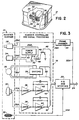
- FIG. 1 there is illustrated a block diagram of a new and improved image recognition system according to the invention generally designated by the reference numeral 10. While the image recognition system 10 is depicted and generally described herein for use with a television receiver to identify individual members of a viewing audience, the principles of the present invention are also applicable to other image recognition systems.
- the image recognition system 10 includes an audience scanner 12 for scanning and capturing an image of the viewing audience members within a monitored area, and a control command processor subsystem 14 for performing control operations and for storing and processing captured images.
- a data transfer device 16 is used for periodically transferring stored data to a central computer (not shown) of the television audience measurement and/or marketing data collection systems.
- the image recognition system 10 includes a scanner controller and signal processing circuit 18 illustrated in FIG. 3 for providing illumination and motor control signals to the audience scanner 12 and for locating and capturing the images of the audience members within the monitored area, an analog-to-digital A/D and interface circuit 20 illustrated in FIG.
- the frame grabber 22 can be implemented with, for example, such as, a model DT2803 low-cost Frame Grabber for use with IBM personal computers, manufactured and sold by Data Translation Inc., of Marlborough, Massachusetts.
- the scanner controller and signal processing circuit 18 is connected to the A/D and interface circuit 20 and the frame grabber circuit 22 via a plurality of signal lines and a video cable 28A.
- a data, address and control bus 24 connects the control command processor subsystem 14 to the A/D and interface circuit 20 and the frame grabber circuit 22.
- An audience recognition subsystem 26 for learning and for recognizing feature image signatures of the images of the audience members is illustrated in FIGS. 6 and 7.
- the audience scanner 12 includes a video camera 28 for capturing a video image, a pair of infrared sensors 30 for locating individual audience members, an ultrasound transducer 32 for identifying a distance measurement between the camera 28 and a particular located audience member, a pair of infrared illumination devices 34 for covert illumination of the monitored area, and a scanner drive 36 for scanning the monitored area.
- the video camera 28 provides a video image signal at a line 28A that is applied to the frame grabber 22.
- the output of the frame grabber 22 is applied to the data, address and control bus 24 via a line 22A.
- An infrared video camera for example, such as a Model CCD1200 IR Microcam, manufactured and sold by Electrophysics Corporation of Nutley, New Jersey, may be employed for the video camera 28.
- a sensed infrared signal at a line 30A provided by the infrared sensors 30 is applied to circuit 18.
- a parallel opposed dual pyroelectric infrared detector used in conjunction with an optic focusing device including a pair of fixed surface mirrors and a Fresnel lens, may be used for each of the infrared sensors 30, for example, such as an Eltec Model 429 and an Eltec Model 826C manufactured and sold by Eltec Instruments, Inc. of Daytona Beach, Florida.
- the sensed voltage signal output of each infrared sensor 30 at lines 30A corresponds to the temperature distribution of the monitored area.
- Each of the sensed infrared signals at lines 30A is applied to one of a pair of preamplifier devices 38.
- Each amplified infrared signal is applied to a corresponding one of a pair of low pass filters 40 for providing filtered infrared signals at lines 42 applied to the A/D and interface circuit 20.
- a dual operational amplifier integrated circuit device such as a device type LM358 arranged with appropriate feedback and biasing devices can be used for the preamplifiers 38 and low pass filters 40.
- the ultrasound transducer 32 such as a 50 KHz electrostatic transducer, for transmitting and for receiving ultrasonic signals provides a distance pulse echo signal at a line 32A that is applied to the A/D and interface circuit 20.
- Covert illumination of the monitored area is provided by the pair of infrared illumination devices 34 (one shown in FIG. 3) with each illumination device 34 operatively controlled by an activating signal applied at a line 34A.
- a switching transistor 44 such as an NPN bipolar transistor, is turned on by a control signal at a line 46 applied to its base from the A/D and interface circuit 20.
- a relay 48 connected between the collector of transistor 44 and a power supply 50 is energized by transistor 44 to close its relay contacts 52. The output of the power supply 50 is applied at the line 34A by the closed relay contacts 52. The output of the power supply 50 is connected to the video camera 28 at a line 28B.
- the scanner drive 36 such as a stepping motor is operatively controlled by a scanner controller 54 for stepwise angular rotation of the video camera 28 for scanning the monitored area.
- a scanner controller 54 for stepwise angular rotation of the video camera 28 for scanning the monitored area.
- An integrated circuit stepper motor driver device type SAA1042 manufactured and sold by Motorola Inc. can be employed for the scanner controller 38.
- Control signals at a pair of lines 56 are applied to the scanner controller 38 from the A/D and interface circuit 20.
- FIG. 4 provides a partly schematic and block diagram representation of the A/D and interface circuit 20.
- the filtered infrared signals at lines 42 are applied to an analog-to-digital A/D converter 58 which generates digital representations of the processed infrared signals.
- the digitized signals are applied to the control command processor subsystem 14 to identify directions within the monitored area corresponding to the possible locations of individual audience members.
- An ultrasound range module 60 drives the ultrasound transducer 32 for transmitting an ultrasonic burst signal and for receiving an echo signal at line 32A responsive to an enable or initiate input signal applied by the control/command processor 14 via a peripheral interface adapter (PIA) 62 at a line ENABLE.
- PDA peripheral interface adapter
- the control command processor subsystem 14 utilizes the identified angle signal to initiate operation of the ultrasound range module 58.
- a peripheral interface adapter device type 6522 manufactured by Rockwell International can be used for the PIA 62.
- Interrupt control signals IRQ2-IRQ7 at the processor subsystem data, address and control bus 24 from the PIA 62 are applied to the processor subsystem 14.
- the PIA 62 couples data, timing and control signals between the control/command processor 14 and the scanner controller and signal processing circuit 18.
- the PIA 62 also enables bidirectional communications between the image recognition system 10 and a host system for a particular application.
- a home unit of the type as described in United States patent 4,697,209 to David A. Kiewit and Daozheng Lu may be connected to the PIA 62.
- An integrated circuit 8-bit A/D converter device type AD7828 manufactured and sold by Analog Devices can be employed for the A/D converter 58.
- a sonar ranging module for example, such as an integrated circuit device type SN28827 manufactured and sold by Texas Instruments may be used for the ultrasound range module 60.
- An output echo signal of the ultrasound range module 60 is coupled to the control/command processor subsystem 14 via an amplifier/limiter stage 64 and the A/D converter 58 which converts the echo signal to a suitable format for use by the control command processor subsystem 14.
- the processed echo signal representative of distance between the scanner 12 and the located individual audience member is utilized by the control command processor subsystem 14 for adjusting the zooming functions of the video image data during processing.
- An octal bus transceiver 66 such as an integrated circuit device type 74HC245 manufactured and sold by Motorola Inc., provides bidirectional data communications between the processor subsystem data, address and control bus 24 and the A/D converter 58.
- a pair of octal bus transceivers 68 and 70 and a programmable array logic (PLA) device 72 provide bidirectional address and control communications between the processor subsystem data, address and control bus 24 and the PIA 62 and A/D converter 58.
- PDA programmable array logic
- An integrated circuit device type 74HC244 manufactured and sold by Motorola Inc. can be used for each of the octal bus transceivers 68 and 70.
- An oscillator device 74, such as a 2 MHz oscillator and a timing logic circuit 76 provide timing signals to the PIA 62 and the PLA 72.
- PLA 72 can be implemented with, for example, an integrated circuit device PLS153 manufactured and sold by Rockwell International.
- FIG. 5 provides a block diagram representation of the control command processor subsystem 14 of the image recognition system 10.
- the control command processor subsystem 14 includes a central processing unit 78, such as, an Intel 80286 high performance 16-bit microprocessor with integrated memory management and adapted for multi-tasking systems and an optional associated memory device 80.
- the central processing unit 78 is programmable to perform the control and signal processing functions and includes, in known manner, asynchronous input signal timing and clock control bus timing functions.
- the control command processor subsystem 14 further may include an image display 82, a computer display 84 and a keyboard 86 for use during the installation of the image recognition system 10.
- the control command processor subsystem 14 can be implemented with a personal computer system, such as an IBM PC/AT.
- Control signals at the processor bus 24 from the central processing unit 78 are applied via the signal line 46 of the PIA 62 (FIG. 4) to the illumination controller switching transistor 44 (FIG. 3) for controlling illumination of the monitored area.
- Motor control signals at the processor bus 24 from the central processing unit 78 are applied via the lines 56 of the PIA 62 (FIG. 4) to the scanner controller 54 (FIG. 3) which are translated and applied to the stepping motor 36.
- Feedback position signals may be provided to the central processing unit 78.
- FIGS. 6 and 7 provide a block diagram representation of the audience recognition subsystem 26. Bidirectional communications are provided between the central processing unit 78 and the frame grabber 22 and the audience recognition subsystem 26 via the data, address and control bus 24. Referring initially to FIG. 6, a learning operational mode of the audience recognition subsystem 26 is illustrated.
- the processed infrared image output signal from the frame grabber 22 is applied to an image acquisition block 88 to generate a digital representation of the infrared image signal.
- the digital infrared image representation is applied to a face image location block 92 that acquires a variable portion (mxn) pixels of the digitized image signal.
- the values of m and n are variable between 32 and 256 as determined for a particular identified distance between the scanner 12 and the located audience member.
- a gray-level subimage output of the face image location block 92 at a line G-Sub is applied to a normalization block 94.
- the normalized output of block 94 is applied to a thresholding block 96 to provide a thresholding, binary level face image output at a line B-Sub.
- Each pixel of the (mxn) thresholding, binary level face or B-Sub image is represented by a single binary digit or bit, or 2500 bits for the 50x50 pixels.
- the B-Sub image signal is applied to a feature signature extraction block 98.
- An extracted pattern image signature output of the feature signature extraction block 98 is stored in an individual face storage library (IFL) 100.
- a stop function flag is set at stop blocks 102 for updating the image libraries performed by the control command processor subsystem 14 as illustrated in FIG. 8A.
- FIG. 6A provides a graphical representation of a B-sub image including mxn pixels. Each of the mxn pixels is either a zero or a one.
- the B-sub image pixel data is utilized to extract the pattern image signature for storing in the learning operational mode (FIG. 6) and to extract the pattern image signature for comparing with the feature image signatures in the recognition operational mode illustrated in FIG. 7.
- a pseudo random predetermined sequence of the mxn B-Sub image bits defines a predetermined number T of feature positions used for storing the extracted feature signature output of the feature signature extraction blocks 98.
- Each feature position has a predetermined length L, where the value of L is between 3 and 10.
- T a total memory space for each of the pattern or face image signatures equals T multiplied by b or, for example, 357 positions x 16 bytes/position or 5712 bytes.
- the corresponding memory space is represented by the reference character 100 corresponding to the IFL block 100.
- the logic steps performed for storing the individual face pattern image signatures are described with respect to FIG. 8B.
- a distinct memory space of a predetermined capacity is defined for each of the individual face pattern image signatures within the image face library IFL block 100.
- individual face signatures TxP
- Multiple face images are learned for each of the audience members P by sequentially processing a series of video images of the video camera 28 by the image signal processing blocks of FIG. 6 for each of the audience members. All of the resulting extracted pattern image signatures for each of the audience members are stored in the particular corresponding memory space of the IFL memory spaces.
- FIG. 7 provides a block diagram representation of the recognition mode of the audience recognition subsystem 26.
- the digital representation of the infrared image signal from the image acquisition block 88 corresponding to an identified direction of an audience member by the processor subsystem 14 is applied to a zooming and head location block 104.
- a gray-level subimage output G-Sub of the zooming and head location block 104 is applied to a normalization block 106.
- the normalized output of block 106 is applied to a thresholding block 108 to provide a thresholding, binary level image output B-Sub.
- a feature signature is extracted from the B-Sub image at a feature signature extraction block 110.
- the extracted B-Sub image feature signature is compared with each of the pattern image signatures stored in the individual face library as illustrated at a block 112 to identify a match.
- a particular audience member is identified when the compared signatures exceed a predetermined correlation threshold value corresponding to the best matching rate or highest correlation with an individual face pattern image signature in the individual face library is identified at a conclusion block 114. If such a conclusion can not be reached, a next gray-level subimage output G-Sub of the zooming and head location block 104 is sequentially processed until a satisfactory conclusion can be made.
- the satisfactory conclusions include both "identified" and "unidentified” audience members. The logic steps performed for recognizing the particular individual audience member are described with respect to FIG. 8B.
- An output signal at a line 116 is then stored corresponding to the particular identified individual member of the viewing audience.
- the thus identified individual viewing member data can be stored together with other parameter data of a television data collection system, such as channel reception of a monitored receiver.
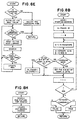
- FIG. 8A there is a main flow chart illustrating the logical steps performed by the control command processor subsystem 14 of the image recognition system 10.
- the sequential steps begin with an initialization routine. Then if a stop function is set, the particular pattern image signature memory space can be updated to include the feature image signature stored at IFL block 100 of FIG. 6. Otherwise, it is determined whether any function or mode has been selected, such as by a remote control or keyboard entry. If yes, then the selected function or mode is set or updated and then performed. Otherwise, the next sequential function or mode of modes 1-7 is performed.
- FIG. 8B is a flow chart illustrating the logic steps performed for learning and recognizing the individual face.
- the sequential operations begin by setting a memory space address ADDR to the starting address with N-found set to zero.
- the corresponding bit position B bit of ADDR + A byte is determined by the particular feature value S, where S is between 0 and 127, A equals an integer value S/8 and B equals S mod 8 or the residue of S after A bytes.
- S is between 0 and 127
- A equals an integer value S/8
- B equals S mod 8 or the residue of S after A bytes.
- An individual audience member face image may be learned multiple times (R) with R possible different extracted signatures resulting, depending on any changed facial expressions or various profiles of the audience member.
- R Each of the extracted feature signatures is sequentially stored within the corresponding pattern image signature memory space for the particular audience member by repeating the sequential signal processing of FIG. 6 and the learning or storing steps of FIG. 8B.
- the sequential steps for the recognition mode are performed, such as at the recognition for IFL block 112 when the B-Sub image extracted feature signature is compared with each of the individual pattern image signatures.
- the resulting N-found value is compared with a threshold value. If resulting N-found value is less than the threshold value, then a FALSE or no recognition for the particular IFL is indicated. If resulting N-found value is greater than or equal to the threshold value, then a TRUE or a recognition of the particular IFL is indicated.
- FIG. 8C is a flow chart illustrating an operational function or mode 1 logical steps performed to add to the individual pattern image signatures memory space or library. The sequential steps begin with a get and display a picture subroutine illustrated in FIG. 8D. Next a search all libraries subroutine illustrated in FIG. 8E is performed. The results are displayed and added to the library.
- the get and display a picture subroutine of FIG. 8D starts with an image acquisition step (block 88 of FIG. 6).
- the infrared video image is processed (blocks 92, 94 and 96 of FIG. 6) to provide a binary picture (B-sub image).
- a ratio of the ones in the resulting binary picture is calculated and the resulting binary picture is displayed.
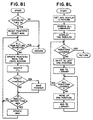
- the search all libraries subroutine begins with a check of the exposure time based on the calculated ratio of ones and if adjustment is required, then the sequential operation return without searching the libraries. Otherwise, if adjustment of the exposure time is not required, then an initial MAX value is set for the predetermined N-found value.
- a first library is searched (block 112 of FIG. 7 and FIG. 8B) and if the result N-found value is greater than the initial MAX value, then the MAX value is updated. Otherwise the MAX value is not changed. Then a next library is searched and the result is compared to the resulting MAX value and adjusted, until all the libraries have been searched.
- FIG. 8F is a flow chart illustrating an operational function or mode 2 logical steps performed to verify and add to library. The sequential steps begin with the get and display the picture subroutine illustrated in FIG. 8D. Next the search all libraries subroutine illustrated in FIG. 8E is performed. The results are displayed, verified by a user operator of the system 10, then added to an identified correct library.
- FIG. 8G is a flow chart illustrating an operational function or mode 3 logical steps performed to locate, display and recognize the faces. The sequential steps begin with a get and display the picture subroutine illustrated in FIG. 8D. Next the search all libraries subroutine illustrated in FIG. 8E is performed. The results are displayed.
- FIG. 8H is a flow chart illustrating an operational function or mode 4 logical steps performed to locate the faces. The sequential steps begin with a search raw picture for heads subroutine illustrated in FIG. 8I. Next a locate and search head(s) subroutine illustrated in FIG. 8J is performed.
- the search raw picture for head(s) subroutine begins with a check of the exposure time and if adjustment is required, then the sequential operation return without performing any searching for heads. Otherwise, if adjustment of the exposure time is not required, then an initial MAX value is set for the predetermined N-found value and a search area pointer i is reset.
- the first search area matrix is identified and sequentially compared with each of the individual pattern image signatures (IFM block 112 of FIG. 7 and FIG. 8B). The result is compared with the set predetermined correlation threshold MAX value, and if the result is greater than the initial MAX value, then that search area pointer is saved and the MAX value is updated. Otherwise, the search area pointer is not saved and the MAX value is not changed. Then the search area pointer value is updated and the next search area matrix is identified and the sequential steps are repeated until the total raw picture has been searched.
- FIG. 8J illustrates the locate and search head(s) subroutine performed by the control command processor subsystem 14 in the mode 4. If one search area pointer is stored in the subroutine of FIG. 8I, then the search area window is set to the identified search area matrix by the saved pointer value which corresponds to the head image portion. The exposure time is adjusted and the search all libraries subroutine of FIG. 8E is performed and the results are displayed.
- the MAX value is reset for a predetermined initial value. Then the search area window is set to the first identified search area matrix by the first saved pointer value which corresponds to a first head image portion. A local normalization is performed on the search area matrix data and the search all libraries subroutine of FIG. 8E is performed, and if the result is greater than the initial MAX value, then the MAX value is updated. Otherwise the MAX value is not changed. Then a next search area window is set to the next saved pointer value which corresponds to a next head image portion and the sequential steps are repeated until all the head image portions have been searched. Then the search area window is set to the identified search area matrix having the highest MAX value which corresponds to the head image portion. A local normalization is performed on the search area matrix data and the search all libraries subroutine of FIG. 8E is performed and the results are displayed.
- FIG. 8K is a flow chart illustrating an operational function or mode 5 logical steps performed to scan and search the monitored area. The sequential steps begin with scanning of the monitored area. Then the video camera 28 is pointed to audience members within the monitored area and the mode 4 operations of FIG. 8H are performed.
- FIG. 8L is a flow chart illustrating an operational function or mode 6 logical steps performed to shift and learn.
- the sequential steps begin with the get and display the picture subroutine illustrated in FIG. 8D.
- the search all libraries subroutine illustrated in FIG. 8E is performed.
- the results are displayed and if all positions have been learned, then the sequential operation return without adding to the library. Otherwise, the audience member image is shifted to the left one position and added to the pattern image signature IFL. Then the audience member image is moved up one position and sequentially repeated until all positions have been learned and added to the library.
- FIG. 8M is a flow chart illustrating an operational function or mode 7 logical steps performed to search and pause.
- the sequential steps begin with the search raw picture for heads subroutine illustrated in FIG. 8I.
- the locate and search head(s) subroutine illustrated in FIG. 8J is performed.
- a continue decision is yes, the sequential mode 7 steps are repeated.
Abstract
Description
- The present invention relates generally to image recognition systems for use with television audience measurement and marketing data collection systems, and more particularly to image recognition systems for identifying predetermined individual members of a viewing audience.
- Manual systems for determining the viewing/listening habits of the public are prone to inaccuracies resulting from the entry of erroneous data that may be intentionally or unintentionally entered and are slow in acquiring data.
- United States Patent No. 3,056,135 describes a method and apparatus for automatically determining the listening habits of wave signal receiver users. The method disclosed in this patent provides a record of the number and types of persons using a wave signal receiver by monitoring the operational conditions of the receiver and utilizing both strategically placed switches for counting the number of persons entering, leaving and within a particular area and a photographic recorder for periodically recording the composition of the audience. A mailable magazine provides a record of both the audience composition and the receiver operation information for manual processing by a survey organization. Thus a disadvantage is that acquiring data is slow and further many viewing audience members object to being identified from the photographic record.
- United States Patent No. 4,644,509 discloses an ultrasonic, pulse-echo method and apparatus for determining the number of persons in the audience and the composition of the audience of a radio receiver and/or a television receiver. First and second reflected ultrasonic wave maps of the monitored area are collected, first without people and second with people who may be present in the monitored area. The first collected background defining map is subtracted from the second collected map to obtain a resulting map. The resulting map is processed to identify clusters having a minimum intensity. A cluster size of the thus identified clusters is utilized to identify clusters corresponding to people in an audience.
- United States Patent No. 4,769,697 describes a system employing sensing of individual heat-radiating bodies in a viewing area. The heat-radiating bodies are located by scanning and sorted out by pattern recognition and comparison in an attempt to identify individual human beings yet in doing so the system depends on guesses, no actual identification being obtained.
- On the other hand Japanese Patent Abstract 59-208 699 discloses a system to identity a person sitting in the driver's seat of an automobile. This system employs infrared sensitive image detecting means providing image data from which feature parts are then derived. The feature parts are compared with stored teature parts of distinct individuals to determine if the person in the driver's seat is authorized.
- Various image recognition arrangements and systems are also known for recognizing patterns within a captured video image. However, these conventional pattern recognition systems are impractical and uneconomical for identifying individual audience members of a viewing audience due to the vast information storage and computing requirements that would be needed in these systems.
- It is theretore a main object of the present invention to provide an economical image recognition system for automatically identifying predetermined individual members of a viewing audience in a monitored area.
- This object is achieved by the image recognition system as defined in the appended claims.
- In accordance with a preferred embodiment of the invention a pattern image signature is stored corresponding to each predetermined individual member of the viewing audience to be identified. An audience scanner includes audience locating circuitry for locating individual audience members in the monitored area. A video image is captured for each of the located individual audience members in the monitored area. A pattern image signature is extracted from the captured image. The extracted pattern image signature is compared with each of the stored pattern image signatures to identify a particular one of the predetermined audience members. These steps are repeated to identify all of the located individual audience members in the monitored area.
- Each of the plurality of feature image signatures is stored in a distinct memory space of a predetermined capacity. Each of the feature image signatures is generated by processing a plurality of video images of the face of the individual to be identified. A signature from each of the processed video images is extracted and stored in the corresponding predetermined memory space for the particular feature image signature.
- In the following the invention in a preferred form is explained in connection with the accompanying drawings in which
- FIG 1 is a block diagram of an image recognition system according to the present invention;
- FIG. 2 is a perspective view partly broken away to show interior details of an audience scanner of the image recognition system of FIG. 1;
- FIG. 3 is a partly schematic and block diagram representation of a scanner controller and signal processing circuit of the image recognition system of FIG. 1;
- FIG. 4 is a partly schematic and block diagram representation of an analog-to-digital and interface circuit of the image recognition system of FIG. 1;
- FIG. 5 is a block diagram of a control command processor subsystem of the image recognition system of FIG. 1;
- FIG. 6 is a block diagram of a learning functional portion of an audience recognition subsystem of the image recognition system of FIG. 1;
- FIG. 6A is a graphical representation of a binary subimage and feature identifying logic for extracting and storing an image signature of the image recognition system of FIG. 1;
- FIG. 7 is a block diagram of a recognition functional portion of the audience recognition subsystem of the image recognition system of FIG. 1;
- FIGS. 8A - 8M are flow charts illustrating the logical steps performed by the image recognition system of FIG. 1.
- Referring now to the drawing, with particular attention to FIG. 1, there is illustrated a block diagram of a new and improved image recognition system according to the invention generally designated by the
reference numeral 10. While theimage recognition system 10 is depicted and generally described herein for use with a television receiver to identify individual members of a viewing audience, the principles of the present invention are also applicable to other image recognition systems. - As its major components, the
image recognition system 10 includes anaudience scanner 12 for scanning and capturing an image of the viewing audience members within a monitored area, and a controlcommand processor subsystem 14 for performing control operations and for storing and processing captured images. Adata transfer device 16 is used for periodically transferring stored data to a central computer (not shown) of the television audience measurement and/or marketing data collection systems. Theimage recognition system 10 includes a scanner controller andsignal processing circuit 18 illustrated in FIG. 3 for providing illumination and motor control signals to theaudience scanner 12 and for locating and capturing the images of the audience members within the monitored area, an analog-to-digital A/D andinterface circuit 20 illustrated in FIG. 4 for identifying the distance between audience members and theaudience scanner 12 and aframe grabber 22 for digitizing video images and providing frame buffer memory, timing and control logic. Theframe grabber 22 can be implemented with, for example, such as, a model DT2803 low-cost Frame Grabber for use with IBM personal computers, manufactured and sold by Data Translation Inc., of Marlborough, Massachusetts. The scanner controller andsignal processing circuit 18 is connected to the A/D andinterface circuit 20 and theframe grabber circuit 22 via a plurality of signal lines and avideo cable 28A. A data, address andcontrol bus 24 connects the controlcommand processor subsystem 14 to the A/D andinterface circuit 20 and theframe grabber circuit 22. Anaudience recognition subsystem 26 for learning and for recognizing feature image signatures of the images of the audience members is illustrated in FIGS. 6 and 7. - Referring also to FIGS. 2 and 3, the
audience scanner 12 includes avideo camera 28 for capturing a video image, a pair ofinfrared sensors 30 for locating individual audience members, anultrasound transducer 32 for identifying a distance measurement between thecamera 28 and a particular located audience member, a pair ofinfrared illumination devices 34 for covert illumination of the monitored area, and ascanner drive 36 for scanning the monitored area. Thevideo camera 28 provides a video image signal at aline 28A that is applied to theframe grabber 22. The output of theframe grabber 22 is applied to the data, address andcontrol bus 24 via aline 22A. An infrared video camera, for example, such as a Model CCD1200 IR Microcam, manufactured and sold by Electrophysics Corporation of Nutley, New Jersey, may be employed for thevideo camera 28. - A sensed infrared signal at a
line 30A provided by theinfrared sensors 30 is applied tocircuit 18. A parallel opposed dual pyroelectric infrared detector used in conjunction with an optic focusing device including a pair of fixed surface mirrors and a Fresnel lens, may be used for each of theinfrared sensors 30, for example, such as an Eltec Model 429 and an Eltec Model 826C manufactured and sold by Eltec Instruments, Inc. of Daytona Beach, Florida. The sensed voltage signal output of eachinfrared sensor 30 atlines 30A corresponds to the temperature distribution of the monitored area. Each of the sensed infrared signals atlines 30A is applied to one of a pair ofpreamplifier devices 38. Each amplified infrared signal is applied to a corresponding one of a pair oflow pass filters 40 for providing filtered infrared signals atlines 42 applied to the A/D andinterface circuit 20. A dual operational amplifier integrated circuit device, such as a device type LM358 arranged with appropriate feedback and biasing devices can be used for thepreamplifiers 38 andlow pass filters 40. - The
ultrasound transducer 32, such as a 50 KHz electrostatic transducer, for transmitting and for receiving ultrasonic signals provides a distance pulse echo signal at aline 32A that is applied to the A/D andinterface circuit 20. - Covert illumination of the monitored area is provided by the pair of infrared illumination devices 34 (one shown in FIG. 3) with each
illumination device 34 operatively controlled by an activating signal applied at aline 34A. A Model IRL200 infrared room illuminator manufactured and sold by Electrophysics Corporation of Nutley, New Jersey, may be employed for theillumination devices 34, although various illumination devices such as infrared lasers, light emitting diodes or a filtered flash lamp can be used. Aswitching transistor 44, such as an NPN bipolar transistor, is turned on by a control signal at aline 46 applied to its base from the A/D andinterface circuit 20. Arelay 48 connected between the collector oftransistor 44 and apower supply 50 is energized bytransistor 44 to close itsrelay contacts 52. The output of thepower supply 50 is applied at theline 34A by theclosed relay contacts 52. The output of thepower supply 50 is connected to thevideo camera 28 at a line 28B. - The
scanner drive 36, such as a stepping motor is operatively controlled by ascanner controller 54 for stepwise angular rotation of thevideo camera 28 for scanning the monitored area. An integrated circuit stepper motor driver device type SAA1042 manufactured and sold by Motorola Inc. can be employed for thescanner controller 38. Control signals at a pair oflines 56 are applied to thescanner controller 38 from the A/D andinterface circuit 20. - FIG. 4 provides a partly schematic and block diagram representation of the A/D and
interface circuit 20. The filtered infrared signals atlines 42 are applied to an analog-to-digital A/D converter 58 which generates digital representations of the processed infrared signals. The digitized signals are applied to the controlcommand processor subsystem 14 to identify directions within the monitored area corresponding to the possible locations of individual audience members. Anultrasound range module 60 drives theultrasound transducer 32 for transmitting an ultrasonic burst signal and for receiving an echo signal atline 32A responsive to an enable or initiate input signal applied by the control/command processor 14 via a peripheral interface adapter (PIA) 62 at a line ENABLE. The controlcommand processor subsystem 14 utilizes the identified angle signal to initiate operation of theultrasound range module 58. - A peripheral interface
adapter device type 6522 manufactured by Rockwell International can be used for thePIA 62. Interrupt control signals IRQ2-IRQ7 at the processor subsystem data, address and controlbus 24 from thePIA 62 are applied to theprocessor subsystem 14. ThePIA 62 couples data, timing and control signals between the control/command processor 14 and the scanner controller andsignal processing circuit 18. ThePIA 62 also enables bidirectional communications between theimage recognition system 10 and a host system for a particular application. A home unit of the type as described in United States patent 4,697,209 to David A. Kiewit and Daozheng Lu may be connected to thePIA 62. - An integrated circuit 8-bit A/D converter device type AD7828 manufactured and sold by Analog Devices can be employed for the A/
D converter 58. A sonar ranging module, for example, such as an integrated circuit device type SN28827 manufactured and sold by Texas Instruments may be used for theultrasound range module 60. An output echo signal of theultrasound range module 60 is coupled to the control/command processor subsystem 14 via an amplifier/limiter stage 64 and the A/D converter 58 which converts the echo signal to a suitable format for use by the controlcommand processor subsystem 14. The processed echo signal representative of distance between thescanner 12 and the located individual audience member is utilized by the controlcommand processor subsystem 14 for adjusting the zooming functions of the video image data during processing. - An
octal bus transceiver 66, such as an integrated circuit device type 74HC245 manufactured and sold by Motorola Inc., provides bidirectional data communications between the processor subsystem data, address and controlbus 24 and the A/D converter 58. A pair ofoctal bus transceivers device 72 provide bidirectional address and control communications between the processor subsystem data, address and controlbus 24 and thePIA 62 and A/D converter 58. - An integrated circuit device type 74HC244 manufactured and sold by Motorola Inc. can be used for each of the
octal bus transceivers oscillator device 74, such as a 2 MHz oscillator and a timing logic circuit 76 provide timing signals to thePIA 62 and thePLA 72.PLA 72 can be implemented with, for example, an integrated circuit device PLS153 manufactured and sold by Rockwell International. - FIG. 5 provides a block diagram representation of the control
command processor subsystem 14 of theimage recognition system 10. The controlcommand processor subsystem 14 includes acentral processing unit 78, such as, anIntel 80286 high performance 16-bit microprocessor with integrated memory management and adapted for multi-tasking systems and an optional associatedmemory device 80. Thecentral processing unit 78 is programmable to perform the control and signal processing functions and includes, in known manner, asynchronous input signal timing and clock control bus timing functions. - The control
command processor subsystem 14 further may include animage display 82, acomputer display 84 and akeyboard 86 for use during the installation of theimage recognition system 10. The controlcommand processor subsystem 14 can be implemented with a personal computer system, such as an IBM PC/AT. - Control signals at the
processor bus 24 from thecentral processing unit 78 are applied via thesignal line 46 of the PIA 62 (FIG. 4) to the illumination controller switching transistor 44 (FIG. 3) for controlling illumination of the monitored area. Motor control signals at theprocessor bus 24 from thecentral processing unit 78 are applied via thelines 56 of the PIA 62 (FIG. 4) to the scanner controller 54 (FIG. 3) which are translated and applied to the steppingmotor 36. Feedback position signals may be provided to thecentral processing unit 78. - FIGS. 6 and 7 provide a block diagram representation of the
audience recognition subsystem 26. Bidirectional communications are provided between thecentral processing unit 78 and theframe grabber 22 and theaudience recognition subsystem 26 via the data, address and controlbus 24. Referring initially to FIG. 6, a learning operational mode of theaudience recognition subsystem 26 is illustrated. The processed infrared image output signal from theframe grabber 22 is applied to animage acquisition block 88 to generate a digital representation of the infrared image signal. The digital infrared image representation is applied to a faceimage location block 92 that acquires a variable portion (mxn) pixels of the digitized image signal. The values of m and n are variable between 32 and 256 as determined for a particular identified distance between thescanner 12 and the located audience member. A middle pixel image portion may include, for example, such as m=50 and n=50. A gray-level subimage output of the faceimage location block 92 at a line G-Sub is applied to anormalization block 94. The normalized output ofblock 94 is applied to athresholding block 96 to provide a thresholding, binary level face image output at a line B-Sub. Each pixel of the (mxn) thresholding, binary level face or B-Sub image is represented by a single binary digit or bit, or 2500 bits for the 50x50 pixels. The B-Sub image signal is applied to a featuresignature extraction block 98. An extracted pattern image signature output of the featuresignature extraction block 98 is stored in an individual face storage library (IFL) 100. A stop function flag is set at stop blocks 102 for updating the image libraries performed by the controlcommand processor subsystem 14 as illustrated in FIG. 8A. - FIG. 6A provides a graphical representation of a B-sub image including mxn pixels. Each of the mxn pixels is either a zero or a one. The B-sub image pixel data is utilized to extract the pattern image signature for storing in the learning operational mode (FIG. 6) and to extract the pattern image signature for comparing with the feature image signatures in the recognition operational mode illustrated in FIG. 7.
- A pseudo random predetermined sequence of the mxn B-Sub image bits defines a predetermined number T of feature positions used for storing the extracted feature signature output of the feature signature extraction blocks 98. Each feature position has a predetermined length L, where the value of L is between 3 and 10. Considering a predetermined feature position of length L=7 and with the above example B-Sub image of 2500 bits, a pseudo random sequence of 2500/7 or 357 feature positions results or T=357. Each feature has a value between 0 and (2L-1) or, for example, between 0 and 127 when L=7. A memory space of 2L bits arranged as bytes b, where b equals 2L/8, is used for storing the possible feature values for each of the feature positions or, for example, 2*7 or 128 bits or 16 bytes. Thus a total memory space for each of the pattern or face image signatures equals T multiplied by b or, for example, 357 positions x 16 bytes/position or 5712 bytes.
- FIG. 6A illustrates a plurality of feature positions i=0 through i=(T-1) generally designated by the
reference character 98 corresponding to thefeature extraction block 98. The corresponding memory space is represented by thereference character 100 corresponding to theIFL block 100. The first or i=0 feature position value is stored in a corresponding bit position B in a corresponding byte between 0 and (b-1) within thememory space 98. The logic steps performed for storing the individual face pattern image signatures are described with respect to FIG. 8B. - A distinct memory space of a predetermined capacity is defined for each of the individual face pattern image signatures within the image face library IFL block 100. For example, for a viewing audience including a defined number of audience members P, individual face signatures (TxP) are stored in the corresponding IFL defined memory spaces. Multiple face images are learned for each of the audience members P by sequentially processing a series of video images of the
video camera 28 by the image signal processing blocks of FIG. 6 for each of the audience members. All of the resulting extracted pattern image signatures for each of the audience members are stored in the particular corresponding memory space of the IFL memory spaces. - FIG. 7 provides a block diagram representation of the recognition mode of the
audience recognition subsystem 26. The digital representation of the infrared image signal from theimage acquisition block 88 corresponding to an identified direction of an audience member by theprocessor subsystem 14 is applied to a zooming andhead location block 104. A gray-level subimage output G-Sub of the zooming andhead location block 104 is applied to anormalization block 106. The normalized output ofblock 106 is applied to athresholding block 108 to provide a thresholding, binary level image output B-Sub. A feature signature is extracted from the B-Sub image at a featuresignature extraction block 110. The extracted B-Sub image feature signature is compared with each of the pattern image signatures stored in the individual face library as illustrated at ablock 112 to identify a match. A particular audience member is identified when the compared signatures exceed a predetermined correlation threshold value corresponding to the best matching rate or highest correlation with an individual face pattern image signature in the individual face library is identified at aconclusion block 114. If such a conclusion can not be reached, a next gray-level subimage output G-Sub of the zooming andhead location block 104 is sequentially processed until a satisfactory conclusion can be made. The satisfactory conclusions include both "identified" and "unidentified" audience members. The logic steps performed for recognizing the particular individual audience member are described with respect to FIG. 8B. An output signal at aline 116 is then stored corresponding to the particular identified individual member of the viewing audience. The thus identified individual viewing member data can be stored together with other parameter data of a television data collection system, such as channel reception of a monitored receiver. - Referring to FIG. 8A, there is a main flow chart illustrating the logical steps performed by the control
command processor subsystem 14 of theimage recognition system 10. The sequential steps begin with an initialization routine. Then if a stop function is set, the particular pattern image signature memory space can be updated to include the feature image signature stored at IFL block 100 of FIG. 6. Otherwise, it is determined whether any function or mode has been selected, such as by a remote control or keyboard entry. If yes, then the selected function or mode is set or updated and then performed. Otherwise, the next sequential function or mode of modes 1-7 is performed. - FIG. 8B is a flow chart illustrating the logic steps performed for learning and recognizing the individual face. The sequential operations begin by setting a memory space address ADDR to the starting address with N-found set to zero. In the learning mode, an identified feature value from the B-Sub image is set to a corresponding bit position, starting with feature position i=0 and repeated for each feature position to i=356. The corresponding bit position B bit of ADDR + A byte, is determined by the particular feature value S, where S is between 0 and 127, A equals an integer value S/8 and B equals
S mod 8 or the residue of S after A bytes. For example, a feature value S=114 from the B-Sub image for the feature position i=0 is set to the 2nd bit of ADDR + 14 byte. - An individual audience member face image may be learned multiple times (R) with R possible different extracted signatures resulting, depending on any changed facial expressions or various profiles of the audience member. Each of the extracted feature signatures is sequentially stored within the corresponding pattern image signature memory space for the particular audience member by repeating the sequential signal processing of FIG. 6 and the learning or storing steps of FIG. 8B.
- Otherwise if not in the learning mode, then the sequential steps for the recognition mode are performed, such as at the recognition for IFL block 112 when the B-Sub image extracted feature signature is compared with each of the individual pattern image signatures.
- In the recognition mode, the identified feature value from the B-Sub image is compared to a corresponding bit position, starting with feature position i=0 and repeated for each feature position to i=356. If the corresponding bit position is set, a match is indicated and the N-found value is incremented by one. Otherwise, if the corresponding bit position is not set, nonmatching is indicated and the N-found value is not changed. The next incremental feature position is then compared to the corresponding bit position for the identified feature value.
- After the last feature position i=356 has been identified and compared to identify a match, then the resulting N-found value is compared with a threshold value. If resulting N-found value is less than the threshold value, then a FALSE or no recognition for the particular IFL is indicated. If resulting N-found value is greater than or equal to the threshold value, then a TRUE or a recognition of the particular IFL is indicated.
- FIG. 8C is a flow chart illustrating an operational function or
mode 1 logical steps performed to add to the individual pattern image signatures memory space or library. The sequential steps begin with a get and display a picture subroutine illustrated in FIG. 8D. Next a search all libraries subroutine illustrated in FIG. 8E is performed. The results are displayed and added to the library. - The get and display a picture subroutine of FIG. 8D starts with an image acquisition step (block 88 of FIG. 6). The infrared video image is processed (blocks 92, 94 and 96 of FIG. 6) to provide a binary picture (B-sub image). A ratio of the ones in the resulting binary picture is calculated and the resulting binary picture is displayed.
- In FIG. 8E, the search all libraries subroutine begins with a check of the exposure time based on the calculated ratio of ones and if adjustment is required, then the sequential operation return without searching the libraries. Otherwise, if adjustment of the exposure time is not required, then an initial MAX value is set for the predetermined N-found value. A first library is searched (block 112 of FIG. 7 and FIG. 8B) and if the result N-found value is greater than the initial MAX value, then the MAX value is updated. Otherwise the MAX value is not changed. Then a next library is searched and the result is compared to the resulting MAX value and adjusted, until all the libraries have been searched.
- FIG. 8F is a flow chart illustrating an operational function or
mode 2 logical steps performed to verify and add to library. The sequential steps begin with the get and display the picture subroutine illustrated in FIG. 8D. Next the search all libraries subroutine illustrated in FIG. 8E is performed. The results are displayed, verified by a user operator of thesystem 10, then added to an identified correct library. - FIG. 8G is a flow chart illustrating an operational function or
mode 3 logical steps performed to locate, display and recognize the faces. The sequential steps begin with a get and display the picture subroutine illustrated in FIG. 8D. Next the search all libraries subroutine illustrated in FIG. 8E is performed. The results are displayed. - FIG. 8H is a flow chart illustrating an operational function or
mode 4 logical steps performed to locate the faces. The sequential steps begin with a search raw picture for heads subroutine illustrated in FIG. 8I. Next a locate and search head(s) subroutine illustrated in FIG. 8J is performed. - In FIG. 8I, the search raw picture for head(s) subroutine begins with a check of the exposure time and if adjustment is required, then the sequential operation return without performing any searching for heads. Otherwise, if adjustment of the exposure time is not required, then an initial MAX value is set for the predetermined N-found value and a search area pointer i is reset. The first search area matrix is identified and sequentially compared with each of the individual pattern image signatures (IFM block 112 of FIG. 7 and FIG. 8B). The result is compared with the set predetermined correlation threshold MAX value, and if the result is greater than the initial MAX value, then that search area pointer is saved and the MAX value is updated. Otherwise, the search area pointer is not saved and the MAX value is not changed. Then the search area pointer value is updated and the next search area matrix is identified and the sequential steps are repeated until the total raw picture has been searched.
- FIG. 8J illustrates the locate and search head(s) subroutine performed by the control
command processor subsystem 14 in themode 4. If one search area pointer is stored in the subroutine of FIG. 8I, then the search area window is set to the identified search area matrix by the saved pointer value which corresponds to the head image portion. The exposure time is adjusted and the search all libraries subroutine of FIG. 8E is performed and the results are displayed. - Otherwise, if more than one pointer value is stored in the subroutine of FIG. 8I, then the MAX value is reset for a predetermined initial value. Then the search area window is set to the first identified search area matrix by the first saved pointer value which corresponds to a first head image portion. A local normalization is performed on the search area matrix data and the search all libraries subroutine of FIG. 8E is performed, and if the result is greater than the initial MAX value, then the MAX value is updated. Otherwise the MAX value is not changed. Then a next search area window is set to the next saved pointer value which corresponds to a next head image portion and the sequential steps are repeated until all the head image portions have been searched. Then the search area window is set to the identified search area matrix having the highest MAX value which corresponds to the head image portion. A local normalization is performed on the search area matrix data and the search all libraries subroutine of FIG. 8E is performed and the results are displayed.
- FIG. 8K is a flow chart illustrating an operational function or
mode 5 logical steps performed to scan and search the monitored area. The sequential steps begin with scanning of the monitored area. Then thevideo camera 28 is pointed to audience members within the monitored area and themode 4 operations of FIG. 8H are performed. - FIG. 8L is a flow chart illustrating an operational function or
mode 6 logical steps performed to shift and learn. The sequential steps begin with the get and display the picture subroutine illustrated in FIG. 8D. Next the search all libraries subroutine illustrated in FIG. 8E is performed. The results are displayed and if all positions have been learned, then the sequential operation return without adding to the library. Otherwise, the audience member image is shifted to the left one position and added to the pattern image signature IFL. Then the audience member image is moved up one position and sequentially repeated until all positions have been learned and added to the library. - FIG. 8M is a flow chart illustrating an operational function or
mode 7 logical steps performed to search and pause. The sequential steps begin with the search raw picture for heads subroutine illustrated in FIG. 8I. Next the locate and search head(s) subroutine illustrated in FIG. 8J is performed. Then if a continue decision is yes, thesequential mode 7 steps are repeated. - Although the present invention has been described in connection with details of a preferred embodiment, many alterations and modifications may be made without departing from the invention. Accordingly, it is intended that all such alterations and modifications be considered that are within the scope of the invention as defined in the appended claims.
Claims (16)
- An image recognition system (10) designed to identify members of an audience in a monitored area and including:- image capturing means (12, 18, 22) for capturing images of said monitored area,- member locating means (12, 14, Fig. 8K) for locating members of the viewing audience in the monitored area,- image processing means (18) for obtaining current image representations from said captured images,- memory means (14) for storing reference image representations,- comparing means (14) for comparing said current and stored image representations to obtain resulting representations, and- processing means for processing said resulting representations to define individual audience members in said monitored area,characterized in- that said image capturing means (12, 18, 22) comprise optical sensing means (28) capable of providing high resolution images,- that said image processing means (18 etc.) include locating means (92, 104) for locating heads of audience members in said high resolution images and scaling means (94, 106) for scaling image portions corresponding to thus located heads to a standard size, and- that said current as well as said stored image representations are in the form of signatures corresponding to the heads of individual audience members and based on the pixel values of the scaled image portions at certain positions.
- The image recognition system (10) as recited in claim 1 wherein said member locating means (12, 14, Figure 8K) include an infrared detector (30) for providing a temperature representative signal (30A) of the monitored area.
- The image recognition system (10) as recited in claim 2 further comprising processing means (38, 40, 20, 14) for processing said temperature representative signal to provide a direction signal representative of the direction of each of said located members relative to said member locating means (12, 14, and Figure 8K).
- The image recognition system (10) as recited in claim 3 wherein said member locating means (12, 14, and Figure 8K) further includes ultrasonic means (32) responsive to said direction signal for providing a distance signal (32A) representative of the distance of each of said located members from said member locating means.
- The image recognition system (10) as recited in claim 4 wherein said ultrasonic means (32) includes means (60) for transmitting an ultrasonic pulse echo signal, means (64, 58) for detecting a reflected pulse echo signal and means (78) for processing said detected pulse echo signal for providing said distance signal.
- The image recognition system (10) as recited in claim 2 wherein said member locating means (12, 14, and Figure 8K) further include scanner means (36) for scanning said monitored area.
- The image recognition system (10) as recited in claim 6, wherein said scanner means (36) are designed for providing angular rotation of said infrared detector (30) in a plane to provide said temperature representative signal (30A) of the monitored area.
- The image recognition system (10) as recited in claim 1 wherein said image capturing means (12, 18, 22) include an infrared video camera (28) for providing a video image signal (28A).
- The image recognition system (10) as recited in claims 3, 6 and 8, when combined, wherein said scanner means (36) carry said infrared detector (30) and said infrared video camera (28) for capturing an image of each located individual member in the monitored area and responsive to said direction signal.
- The image recognition system (10) as recited in claim 8 wherein said comparing means (14) include:processing means (88, 104, 106, 108) for processing each said captured video image to provide a digitized image signal; andextracting means (110) for extracting a pattern signature from said digitized image signal.
- The image recognition system (10) as recited in claim 10 wherein said digitized image signal comprises a digitized gray level image (104, G-SUB).
- The image recognition system (10) as recited in claim 10 wherein said digitized image signal comprises a thresholded binary image (108, B-SUB).
- The image recognition sytem (10) as recited in claim 10 wherein said extracting means (110) include:means (98 and Figure 8B) for extracting a numerical feature value (S) for each of a plurality of predefined feature positions (i = 0 to i = (T-1)) from said digitized image signal; andmeans (100 and Figure 8B) for identifying a memory location (B = ADDR + A byte) corresponding to said feature value (S) for each of said plurality of predefined feature positions.
- The image recognition system (10) as recited in claim 13 wherein said comparing means (14) further include:means (112 and Figure 8B) for calculating a number of matching memory locations (N-FOUND) with each of said pattern image signatures; andmeans (114 and Figure 8B) for identifying a match responsive to said calculated number (N-FOUND) if said calculated number is greater than a predetermined threshold value (THRESHOLD).
- The image recognition system (10) as recited in claim 14 wherein said comparing means (14) further include:
means (114 and Figure 8B) for identifying a highest matching value of a series of matching values to identify a predetermined audience member. - The image recognition system (10) as recited in claim 2 or 8 further comprising covert illumination means (34) for illuminating the monitored area, said covert illumination means including at least one infrared illuminator.
Applications Claiming Priority (2)
| Application Number | Priority Date | Filing Date | Title |
|---|---|---|---|
| US07/244,916 US4858000A (en) | 1988-09-14 | 1988-09-14 | Image recognition audience measurement system and method |
| US244916 | 1988-09-14 |
Publications (3)
| Publication Number | Publication Date |
|---|---|
| EP0358911A2 EP0358911A2 (en) | 1990-03-21 |
| EP0358911A3 EP0358911A3 (en) | 1990-12-05 |
| EP0358911B1 true EP0358911B1 (en) | 1996-09-18 |
Family
ID=22924602
Family Applications (1)
| Application Number | Title | Priority Date | Filing Date |
|---|---|---|---|
| EP89113972A Expired - Lifetime EP0358911B1 (en) | 1988-09-14 | 1989-07-28 | Image recognition audience measurement system |
Country Status (8)
| Country | Link |
|---|---|
| US (1) | US4858000A (en) |
| EP (1) | EP0358911B1 (en) |
| JP (1) | JP2915013B2 (en) |
| AT (1) | ATE143156T1 (en) |
| AU (1) | AU2854389A (en) |
| CA (1) | CA1314621C (en) |
| DE (1) | DE68927215T2 (en) |
| ES (1) | ES2091191T3 (en) |
Families Citing this family (177)
| Publication number | Priority date | Publication date | Assignee | Title |
|---|---|---|---|---|
| US4931865A (en) * | 1988-08-24 | 1990-06-05 | Sebastiano Scarampi | Apparatus and methods for monitoring television viewers |
| US5063603A (en) * | 1989-11-06 | 1991-11-05 | David Sarnoff Research Center, Inc. | Dynamic method for recognizing objects and image processing system therefor |
| US5164992A (en) * | 1990-11-01 | 1992-11-17 | Massachusetts Institute Of Technology | Face recognition system |
| US5245533A (en) * | 1990-12-18 | 1993-09-14 | A. C. Nielsen Company | Marketing research method and system for management of manufacturer's discount coupon offers |
| US5163094A (en) * | 1991-03-20 | 1992-11-10 | Francine J. Prokoski | Method for identifying individuals from analysis of elemental shapes derived from biosensor data |
| JPH0816958B2 (en) * | 1991-12-11 | 1996-02-21 | 茨城警備保障株式会社 | Security surveillance system |
| US5331544A (en) * | 1992-04-23 | 1994-07-19 | A. C. Nielsen Company | Market research method and system for collecting retail store and shopper market research data |
| FR2691033B1 (en) * | 1992-05-05 | 1995-10-06 | Thomson Csf | METHOD AND DEVICE FOR DETECTING A FACE ON A DIGITAL IMAGE AS WELL AS APPLICATION TO TELEVISION AUDIENCE MEASUREMENT AND REMOTE MONITORING. |
| JPH06160507A (en) * | 1992-09-24 | 1994-06-07 | Matsushita Electric Ind Co Ltd | Personnel existence state judging device |
| US5432864A (en) * | 1992-10-05 | 1995-07-11 | Daozheng Lu | Identification card verification system |
| GB9221678D0 (en) * | 1992-10-15 | 1992-11-25 | Taylor Nelson Group Limited | Identifying a received programme stream |
| US5550928A (en) * | 1992-12-15 | 1996-08-27 | A.C. Nielsen Company | Audience measurement system and method |
| US5481294A (en) * | 1993-10-27 | 1996-01-02 | A. C. Nielsen Company | Audience measurement system utilizing ancillary codes and passive signatures |
| US5781650A (en) * | 1994-02-18 | 1998-07-14 | University Of Central Florida | Automatic feature detection and age classification of human faces in digital images |
| US5835616A (en) * | 1994-02-18 | 1998-11-10 | University Of Central Florida | Face detection using templates |
| US5497314A (en) * | 1994-03-07 | 1996-03-05 | Novak; Jeffrey M. | Automated apparatus and method for object recognition at checkout counters |
| US5594934A (en) * | 1994-09-21 | 1997-01-14 | A.C. Nielsen Company | Real time correlation meter |
| US7724919B2 (en) | 1994-10-21 | 2010-05-25 | Digimarc Corporation | Methods and systems for steganographic processing |
| US6560349B1 (en) | 1994-10-21 | 2003-05-06 | Digimarc Corporation | Audio monitoring using steganographic information |
| EP1026521B1 (en) * | 1995-04-12 | 2004-09-29 | Matsushita Electric Industrial Co., Ltd. | Method and apparatus for detecting an object |
| US6321208B1 (en) | 1995-04-19 | 2001-11-20 | Brightstreet.Com, Inc. | Method and system for electronic distribution of product redemption coupons |
| US6760463B2 (en) | 1995-05-08 | 2004-07-06 | Digimarc Corporation | Watermarking methods and media |
| US7805500B2 (en) | 1995-05-08 | 2010-09-28 | Digimarc Corporation | Network linking methods and apparatus |
| US7224819B2 (en) | 1995-05-08 | 2007-05-29 | Digimarc Corporation | Integrating digital watermarks in multimedia content |
| US7917386B2 (en) | 1995-06-16 | 2011-03-29 | Catalina Marketing Corporation | Virtual couponing method and apparatus for use with consumer kiosk |
| US20020178051A1 (en) | 1995-07-25 | 2002-11-28 | Thomas G. Scavone | Interactive marketing network and process using electronic certificates |
| US7711564B2 (en) | 1995-07-27 | 2010-05-04 | Digimarc Corporation | Connected audio and other media objects |
| US6411725B1 (en) | 1995-07-27 | 2002-06-25 | Digimarc Corporation | Watermark enabled video objects |
| US6965682B1 (en) * | 1999-05-19 | 2005-11-15 | Digimarc Corp | Data transmission by watermark proxy |
| US6829368B2 (en) | 2000-01-26 | 2004-12-07 | Digimarc Corporation | Establishing and interacting with on-line media collections using identifiers in media signals |
| US6505160B1 (en) * | 1995-07-27 | 2003-01-07 | Digimarc Corporation | Connected audio and other media objects |
| US7562392B1 (en) | 1999-05-19 | 2009-07-14 | Digimarc Corporation | Methods of interacting with audio and ambient music |
| US6647548B1 (en) | 1996-09-06 | 2003-11-11 | Nielsen Media Research, Inc. | Coded/non-coded program audience measurement system |
| WO1998011494A1 (en) * | 1996-09-16 | 1998-03-19 | Advanced Research Solutions, Llc | Data correlation and analysis tool |
| US5991429A (en) * | 1996-12-06 | 1999-11-23 | Coffin; Jeffrey S. | Facial recognition system for security access and identification |
| US6111517A (en) * | 1996-12-30 | 2000-08-29 | Visionics Corporation | Continuous video monitoring using face recognition for access control |
| US6675383B1 (en) | 1997-01-22 | 2004-01-06 | Nielsen Media Research, Inc. | Source detection apparatus and method for audience measurement |
| US6676127B2 (en) | 1997-03-13 | 2004-01-13 | Shuffle Master, Inc. | Collating and sorting apparatus |
| US6084590A (en) * | 1997-04-07 | 2000-07-04 | Synapix, Inc. | Media production with correlation of image stream and abstract objects in a three-dimensional virtual stage |
| US6124864A (en) * | 1997-04-07 | 2000-09-26 | Synapix, Inc. | Adaptive modeling and segmentation of visual image streams |
| US6160907A (en) * | 1997-04-07 | 2000-12-12 | Synapix, Inc. | Iterative three-dimensional process for creating finished media content |
| US6561428B2 (en) | 1997-10-17 | 2003-05-13 | Hand Held Products, Inc. | Imaging device having indicia-controlled image parsing mode |
| US6467089B1 (en) | 1997-12-23 | 2002-10-15 | Nielsen Media Research, Inc. | Audience measurement system incorporating a mobile handset |
| US6266053B1 (en) | 1998-04-03 | 2001-07-24 | Synapix, Inc. | Time inheritance scene graph for representation of media content |
| US6297825B1 (en) | 1998-04-06 | 2001-10-02 | Synapix, Inc. | Temporal smoothing of scene analysis data for image sequence generation |
| US6249285B1 (en) | 1998-04-06 | 2001-06-19 | Synapix, Inc. | Computer assisted mark-up and parameterization for scene analysis |
| US6254096B1 (en) | 1998-04-15 | 2001-07-03 | Shuffle Master, Inc. | Device and method for continuously shuffling cards |
| US6655684B2 (en) | 1998-04-15 | 2003-12-02 | Shuffle Master, Inc. | Device and method for forming and delivering hands from randomly arranged decks of playing cards |
| US7689532B1 (en) | 2000-07-20 | 2010-03-30 | Digimarc Corporation | Using embedded data with file sharing |
| DE69830423D1 (en) | 1998-05-12 | 2005-07-07 | Nielsen Media Res Inc | Device for recording the ratings of digital television |
| US7062073B1 (en) | 1999-01-19 | 2006-06-13 | Tumey David M | Animated toy utilizing artificial intelligence and facial image recognition |
| US6847373B1 (en) | 1999-04-16 | 2005-01-25 | Avid Technology, Inc. | Natural color matching in a video editing system |
| US7302574B2 (en) | 1999-05-19 | 2007-11-27 | Digimarc Corporation | Content identifiers triggering corresponding responses through collaborative processing |
| US7565294B2 (en) | 1999-05-19 | 2009-07-21 | Digimarc Corporation | Methods and systems employing digital content |
| US8023724B2 (en) | 1999-07-22 | 2011-09-20 | Photon-X, Inc. | Apparatus and method of information extraction from electromagnetic energy based upon multi-characteristic spatial geometry processing |
| DE19962201A1 (en) * | 1999-09-06 | 2001-03-15 | Holger Lausch | Determination of people activity within a reception area using cameras and sensors |
| US6993245B1 (en) | 1999-11-18 | 2006-01-31 | Vulcan Patents Llc | Iterative, maximally probable, batch-mode commercial detection for audiovisual content |
| US7661116B2 (en) * | 2000-02-25 | 2010-02-09 | Vulcan Patents Llc | Auction for targeted content |
| AU2001249994A1 (en) | 2000-02-25 | 2001-09-03 | Interval Research Corporation | Method and system for selecting advertisements |
| US8910199B2 (en) * | 2000-02-25 | 2014-12-09 | Interval Licensing Llc | Targeted television content display |
| US7155159B1 (en) * | 2000-03-06 | 2006-12-26 | Lee S. Weinblatt | Audience detection |
| US8473342B1 (en) | 2000-04-05 | 2013-06-25 | Catalina Marketing Corporation | Method and system for generating certificates having unique Id data |
| US8590896B2 (en) | 2000-04-12 | 2013-11-26 | Shuffle Master Gmbh & Co Kg | Card-handling devices and systems |
| KR20010097950A (en) * | 2000-04-27 | 2001-11-08 | 이정숙 | Examination method of audience rating by disposition of viewer and system for the same |
| US8121843B2 (en) | 2000-05-02 | 2012-02-21 | Digimarc Corporation | Fingerprint methods and systems for media signals |
| US6873710B1 (en) * | 2000-06-27 | 2005-03-29 | Koninklijke Philips Electronics N.V. | Method and apparatus for tuning content of information presented to an audience |
| US7203367B2 (en) * | 2000-08-29 | 2007-04-10 | Imageid Ltd. | Indexing, storage and retrieval of digital images |
| JP4095243B2 (en) * | 2000-11-28 | 2008-06-04 | キヤノン株式会社 | A storage medium storing a URL acquisition and processing system and method and a program for executing the method. |
| US8103877B2 (en) | 2000-12-21 | 2012-01-24 | Digimarc Corporation | Content identification and electronic tickets, coupons and credits |
| WO2002051063A1 (en) | 2000-12-21 | 2002-06-27 | Digimarc Corporation | Methods, apparatus and programs for generating and utilizing content signatures |
| US20020114299A1 (en) * | 2000-12-27 | 2002-08-22 | Daozheng Lu | Apparatus and method for measuring tuning of a digital broadcast receiver |
| US7046819B2 (en) | 2001-04-25 | 2006-05-16 | Digimarc Corporation | Encoded reference signal for digital watermarks |
| US7111787B2 (en) | 2001-05-15 | 2006-09-26 | Hand Held Products, Inc. | Multimode image capturing and decoding optical reader |
| US6942151B2 (en) | 2001-05-15 | 2005-09-13 | Welch Allyn Data Collection, Inc. | Optical reader having decoding and image capturing functionality |
| US7131132B1 (en) * | 2001-06-11 | 2006-10-31 | Lucent Technologies Inc. | Automatic access denial |
| US6834807B2 (en) | 2001-07-13 | 2004-12-28 | Hand Held Products, Inc. | Optical reader having a color imager |
| US8011661B2 (en) | 2001-09-28 | 2011-09-06 | Shuffle Master, Inc. | Shuffler with shuffling completion indicator |
| US8337296B2 (en) | 2001-09-28 | 2012-12-25 | SHFL entertaiment, Inc. | Method and apparatus for using upstream communication in a card shuffler |
| US8616552B2 (en) | 2001-09-28 | 2013-12-31 | Shfl Entertainment, Inc. | Methods and apparatuses for an automatic card handling device and communication networks including same |
| US7677565B2 (en) | 2001-09-28 | 2010-03-16 | Shuffle Master, Inc | Card shuffler with card rank and value reading capability |
| US7753373B2 (en) | 2001-09-28 | 2010-07-13 | Shuffle Master, Inc. | Multiple mode card shuffler and card reading device |
| US7305108B2 (en) * | 2001-11-08 | 2007-12-04 | Pelco | Security identification system |
| US7136513B2 (en) * | 2001-11-08 | 2006-11-14 | Pelco | Security identification system |
| US20030131350A1 (en) * | 2002-01-08 | 2003-07-10 | Peiffer John C. | Method and apparatus for identifying a digital audio signal |
| US6801245B2 (en) | 2002-01-18 | 2004-10-05 | Imageid Ltd. | Method for automatic identification and data capture |
| US6886829B2 (en) | 2002-02-08 | 2005-05-03 | Vendingdata Corporation | Image capturing card shuffler |
| US7395062B1 (en) | 2002-09-13 | 2008-07-01 | Nielson Media Research, Inc. A Delaware Corporation | Remote sensing system |
| US7222071B2 (en) | 2002-09-27 | 2007-05-22 | Arbitron Inc. | Audio data receipt/exposure measurement with code monitoring and signature extraction |
| US7203338B2 (en) * | 2002-12-11 | 2007-04-10 | Nielsen Media Research, Inc. | Methods and apparatus to count people appearing in an image |
| US7609853B2 (en) * | 2002-12-11 | 2009-10-27 | The Nielsen Company (Us), Llc | Detecting a composition of an audience |
| US7637430B2 (en) * | 2003-05-12 | 2009-12-29 | Hand Held Products, Inc. | Picture taking optical reader |
| US20040237096A1 (en) * | 2003-05-20 | 2004-11-25 | Comcast Cable Holdings, Llc | Automated in-home observation of user interactions with video devices |
| JP4531501B2 (en) * | 2003-09-29 | 2010-08-25 | 富士フイルム株式会社 | Verification system and program |
| CA2543017C (en) | 2003-10-17 | 2013-11-26 | Nielsen Media Research, Inc. | Portable multi-purpose audience measurement system |
| JPWO2006025284A1 (en) * | 2004-09-02 | 2008-05-08 | 松下電器産業株式会社 | Stream playback device |
| US20060066048A1 (en) | 2004-09-14 | 2006-03-30 | Shuffle Master, Inc. | Magnetic jam detection in a card shuffler |
| US7293712B2 (en) | 2004-10-05 | 2007-11-13 | Hand Held Products, Inc. | System and method to automatically discriminate between a signature and a dataform |
| JP4380524B2 (en) | 2004-12-17 | 2009-12-09 | ソニー株式会社 | Information processing apparatus and information processing method |
| CA2601879C (en) | 2005-03-17 | 2017-07-04 | Nielsen Media Research, Inc. | Methods and apparatus for using audience member behavior information to determine compliance with audience measurement system usage requirements |
| US7631324B2 (en) * | 2005-06-08 | 2009-12-08 | The Nielsen Company (Us), Llc | Methods and apparatus for indirect illumination in electronic media rating systems |
| US7764836B2 (en) | 2005-06-13 | 2010-07-27 | Shuffle Master, Inc. | Card shuffler with card rank and value reading capability using CMOS sensor |
| US20070064208A1 (en) * | 2005-09-07 | 2007-03-22 | Ablaze Development Corporation | Aerial support structure and method for image capture |
| US7587070B2 (en) * | 2005-09-28 | 2009-09-08 | Facedouble, Inc. | Image classification and information retrieval over wireless digital networks and the internet |
| US7450740B2 (en) | 2005-09-28 | 2008-11-11 | Facedouble, Inc. | Image classification and information retrieval over wireless digital networks and the internet |
| US8311294B2 (en) | 2009-09-08 | 2012-11-13 | Facedouble, Inc. | Image classification and information retrieval over wireless digital networks and the internet |
| US8369570B2 (en) | 2005-09-28 | 2013-02-05 | Facedouble, Inc. | Method and system for tagging an image of an individual in a plurality of photos |
| US8600174B2 (en) | 2005-09-28 | 2013-12-03 | Facedouble, Inc. | Method and system for attaching a metatag to a digital image |
| US7599527B2 (en) * | 2005-09-28 | 2009-10-06 | Facedouble, Inc. | Digital image search system and method |
| AU2006327157B2 (en) * | 2005-12-20 | 2013-03-07 | Arbitron Inc. | Methods and systems for conducting research operations |
| US7556266B2 (en) | 2006-03-24 | 2009-07-07 | Shuffle Master Gmbh & Co Kg | Card shuffler with gravity feed system for playing cards |
| US8775252B2 (en) * | 2006-05-04 | 2014-07-08 | National Ict Australia Limited | Electronic media system |
| US8579289B2 (en) | 2006-05-31 | 2013-11-12 | Shfl Entertainment, Inc. | Automatic system and methods for accurate card handling |
| US8342525B2 (en) | 2006-07-05 | 2013-01-01 | Shfl Entertainment, Inc. | Card shuffler with adjacent card infeed and card output compartments |
| US8353513B2 (en) | 2006-05-31 | 2013-01-15 | Shfl Entertainment, Inc. | Card weight for gravity feed input for playing card shuffler |
| WO2007143394A2 (en) | 2006-06-02 | 2007-12-13 | Nielsen Media Research, Inc. | Digital rights management systems and methods for audience measurement |
| US20070300259A1 (en) * | 2006-06-09 | 2007-12-27 | Peter Chan | Systems and methods to support multiple program guides in a home network |
| CN101536503B (en) | 2006-06-15 | 2012-09-26 | 尼尔森(美国)有限公司 | Methods and apparatus to meter content exposure using closed caption information |
| US8070574B2 (en) | 2007-06-06 | 2011-12-06 | Shuffle Master, Inc. | Apparatus, system, method, and computer-readable medium for casino card handling with multiple hand recall feature |
| AU2007272440A1 (en) | 2006-07-12 | 2008-01-17 | Arbitron Inc. | Methods and systems for compliance confirmation and incentives |
| US8919775B2 (en) | 2006-11-10 | 2014-12-30 | Bally Gaming, Inc. | System for billing usage of an automatic card handling device |
| US8669845B1 (en) | 2007-03-30 | 2014-03-11 | Vail Resorts, Inc. | RFID skier monitoring systems and methods |
| US20080251575A1 (en) * | 2007-04-13 | 2008-10-16 | Yourday, Inc. | System for capturing and managing personalized video images over an ip-based control and data local area network |
| US20090171767A1 (en) * | 2007-06-29 | 2009-07-02 | Arbitron, Inc. | Resource efficient research data gathering using portable monitoring devices |
| US20090103909A1 (en) * | 2007-10-17 | 2009-04-23 | Live Event Media, Inc. | Aerial camera support structure |
| US20090158309A1 (en) * | 2007-12-12 | 2009-06-18 | Hankyu Moon | Method and system for media audience measurement and spatial extrapolation based on site, display, crowd, and viewership characterization |
| US8411963B2 (en) * | 2008-08-08 | 2013-04-02 | The Nielsen Company (U.S.), Llc | Methods and apparatus to count persons in a monitored environment |
| US9124769B2 (en) | 2008-10-31 | 2015-09-01 | The Nielsen Company (Us), Llc | Methods and apparatus to verify presentation of media content |
| US8967621B2 (en) | 2009-04-07 | 2015-03-03 | Bally Gaming, Inc. | Card shuffling apparatuses and related methods |
| US7988152B2 (en) | 2009-04-07 | 2011-08-02 | Shuffle Master, Inc. | Playing card shuffler |
| US8538093B2 (en) * | 2009-04-20 | 2013-09-17 | Mark Kodesh | Method and apparatus for encouraging social networking through employment of facial feature comparison and matching |
| US8351712B2 (en) | 2009-04-27 | 2013-01-08 | The Neilsen Company (US), LLC | Methods and apparatus to perform image classification based on pseudorandom features |
| US20110004474A1 (en) * | 2009-07-02 | 2011-01-06 | International Business Machines Corporation | Audience Measurement System Utilizing Voice Recognition Technology |
| GB2474508B (en) * | 2009-10-16 | 2015-12-09 | Norwell Sa | Audience measurement system |
| US8251597B2 (en) * | 2009-10-16 | 2012-08-28 | Wavecam Media, Inc. | Aerial support structure for capturing an image of a target |
| US8549552B2 (en) | 2009-11-03 | 2013-10-01 | The Nielsen Company (Us), Llc | Methods and apparatus to monitor media exposure in vehicles |
| US8775245B2 (en) | 2010-02-11 | 2014-07-08 | News America Marketing Properties, Llc | Secure coupon distribution |
| US8677385B2 (en) | 2010-09-21 | 2014-03-18 | The Nielsen Company (Us), Llc | Methods, apparatus, and systems to collect audience measurement data |
| US20120116252A1 (en) * | 2010-10-13 | 2012-05-10 | The Regents Of The University Of Colorado, A Body Corporate | Systems and methods for detecting body orientation or posture |
| US8800993B2 (en) | 2010-10-14 | 2014-08-12 | Shuffle Master Gmbh & Co Kg | Card handling systems, devices for use in card handling systems and related methods |
| US8918802B2 (en) | 2011-02-28 | 2014-12-23 | The Nielsen Company (Us), Llc | Methods and apparatus to monitor media exposure |
| US8315620B1 (en) | 2011-05-27 | 2012-11-20 | The Nielsen Company (Us), Llc | Methods and apparatus to associate a mobile device with a panelist profile |
| US8657200B2 (en) | 2011-06-20 | 2014-02-25 | Metrologic Instruments, Inc. | Indicia reading terminal with color frame processing |
| US8670609B2 (en) * | 2011-07-22 | 2014-03-11 | Canon Kabushiki Kaisha | Systems and methods for evaluating images |
| US8485527B2 (en) | 2011-07-29 | 2013-07-16 | Savant Shuffler LLC | Card shuffler |
| US9731190B2 (en) | 2011-07-29 | 2017-08-15 | Bally Gaming, Inc. | Method and apparatus for shuffling and handling cards |
| US8620088B2 (en) | 2011-08-31 | 2013-12-31 | The Nielsen Company (Us), Llc | Methods and apparatus to count people in images |
| KR101335915B1 (en) * | 2012-04-24 | 2013-12-03 | 주식회사 슈프리마 | Apparatus for recognizing face |
| US9219559B2 (en) | 2012-05-16 | 2015-12-22 | The Nielsen Company (Us), Llc | Methods and systems for audience measurement |
| US8960674B2 (en) | 2012-07-27 | 2015-02-24 | Bally Gaming, Inc. | Batch card shuffling apparatuses including multi-card storage compartments, and related methods |
| US9378766B2 (en) * | 2012-09-28 | 2016-06-28 | Bally Gaming, Inc. | Card recognition system, card handling device, and method for tuning a card handling device |
| US9511274B2 (en) | 2012-09-28 | 2016-12-06 | Bally Gaming Inc. | Methods for automatically generating a card deck library and master images for a deck of cards, and a related card processing apparatus |
| US11113700B2 (en) | 2012-11-05 | 2021-09-07 | Adobe Inc. | Method and apparatus for associating device user identifiers with content presentation and related events |
| US8769557B1 (en) | 2012-12-27 | 2014-07-01 | The Nielsen Company (Us), Llc | Methods and apparatus to determine engagement levels of audience members |
| US9426525B2 (en) | 2013-12-31 | 2016-08-23 | The Nielsen Company (Us), Llc. | Methods and apparatus to count people in an audience |
| SG11201608344WA (en) | 2014-04-11 | 2016-11-29 | Bally Gaming Inc | Method and apparatus for shuffling and handling cards |
| US9474957B2 (en) | 2014-05-15 | 2016-10-25 | Bally Gaming, Inc. | Playing card handling devices, systems, and methods for verifying sets of cards |
| US9566501B2 (en) | 2014-08-01 | 2017-02-14 | Bally Gaming, Inc. | Hand-forming card shuffling apparatuses including multi-card storage compartments, and related methods |
| USD764599S1 (en) | 2014-08-01 | 2016-08-23 | Bally Gaming, Inc. | Card shuffler device |
| US9551588B2 (en) | 2014-08-29 | 2017-01-24 | The Nielsen Company, LLC | Methods and systems to determine consumer locations based on navigational voice cues |
| US9504905B2 (en) | 2014-09-19 | 2016-11-29 | Bally Gaming, Inc. | Card shuffling device and calibration method |
| US9993719B2 (en) | 2015-12-04 | 2018-06-12 | Shuffle Master Gmbh & Co Kg | Card handling devices and related assemblies and components |
| US10933300B2 (en) | 2016-09-26 | 2021-03-02 | Shuffle Master Gmbh & Co Kg | Card handling devices and related assemblies and components |
| US10339765B2 (en) | 2016-09-26 | 2019-07-02 | Shuffle Master Gmbh & Co Kg | Devices, systems, and related methods for real-time monitoring and display of related data for casino gaming devices |
| US10491940B1 (en) | 2018-08-23 | 2019-11-26 | Rovi Guides, Inc. | Systems and methods for displaying multiple media assets for a plurality of users |
| US11896891B2 (en) | 2018-09-14 | 2024-02-13 | Sg Gaming, Inc. | Card-handling devices and related methods, assemblies, and components |
| US11376489B2 (en) | 2018-09-14 | 2022-07-05 | Sg Gaming, Inc. | Card-handling devices and related methods, assemblies, and components |
| US11338194B2 (en) | 2018-09-28 | 2022-05-24 | Sg Gaming, Inc. | Automatic card shufflers and related methods of automatic jam recovery |
| PH12020050309A1 (en) | 2019-09-10 | 2021-03-22 | Shuffle Master Gmbh And Co Kg | Card-handling devices with defect detection and related methods |
| US11173383B2 (en) | 2019-10-07 | 2021-11-16 | Sg Gaming, Inc. | Card-handling devices and related methods, assemblies, and components |
| US11373425B2 (en) | 2020-06-02 | 2022-06-28 | The Nielsen Company (U.S.), Llc | Methods and apparatus for monitoring an audience of media based on thermal imaging |
| US11711638B2 (en) | 2020-06-29 | 2023-07-25 | The Nielsen Company (Us), Llc | Audience monitoring systems and related methods |
| US11763591B2 (en) | 2020-08-20 | 2023-09-19 | The Nielsen Company (Us), Llc | Methods and apparatus to determine an audience composition based on voice recognition, thermal imaging, and facial recognition |
| US11595723B2 (en) | 2020-08-20 | 2023-02-28 | The Nielsen Company (Us), Llc | Methods and apparatus to determine an audience composition based on voice recognition |
| US11553247B2 (en) | 2020-08-20 | 2023-01-10 | The Nielsen Company (Us), Llc | Methods and apparatus to determine an audience composition based on thermal imaging and facial recognition |
| US11860704B2 (en) | 2021-08-16 | 2024-01-02 | The Nielsen Company (Us), Llc | Methods and apparatus to determine user presence |
| US11758223B2 (en) | 2021-12-23 | 2023-09-12 | The Nielsen Company (Us), Llc | Apparatus, systems, and methods for user presence detection for audience monitoring |
| US11689765B1 (en) | 2021-12-31 | 2023-06-27 | The Nielsen Company (Us), Llc | Methods and apparatus for obfuscated audience identification |
Family Cites Families (11)
| Publication number | Priority date | Publication date | Assignee | Title |
|---|---|---|---|---|
| US3056135A (en) * | 1957-07-09 | 1962-09-25 | A O Nielsen Company | Method and apparatus for automatically determining the listening habits of wave signal receiver users |
| SE365325B (en) * | 1971-11-04 | 1974-03-18 | Rothfjell R | |
| US4697209A (en) * | 1984-04-26 | 1987-09-29 | A. C. Nielsen Company | Methods and apparatus for automatically identifying programs viewed or recorded |
| JPS6184509A (en) * | 1984-10-02 | 1986-04-30 | Nippon Denso Co Ltd | Identifying device for vehicle driver |
| US4712103A (en) * | 1985-12-03 | 1987-12-08 | Motohiro Gotanda | Door lock control system |
| US4644509A (en) * | 1986-01-23 | 1987-02-17 | A. C. Nielsen Company | Ultrasonic audience measurement system and method |
| US4695879A (en) * | 1986-02-07 | 1987-09-22 | Weinblatt Lee S | Television viewer meter |
| US4739398A (en) * | 1986-05-02 | 1988-04-19 | Control Data Corporation | Method, apparatus and system for recognizing broadcast segments |
| US4754487A (en) * | 1986-05-27 | 1988-06-28 | Image Recall Systems, Inc. | Picture storage and retrieval system for various limited storage mediums |
| US4769697A (en) * | 1986-12-17 | 1988-09-06 | R. D. Percy & Company | Passive television audience measuring systems |
| JPS63253792A (en) * | 1987-04-09 | 1988-10-20 | Koichiro Uemura | Television viewership status measuring device |
-
1988
- 1988-09-14 US US07/244,916 patent/US4858000A/en not_active Expired - Lifetime
-
1989
- 1989-01-16 AU AU28543/89A patent/AU2854389A/en not_active Abandoned
- 1989-07-06 CA CA000604883A patent/CA1314621C/en not_active Expired - Fee Related
- 1989-07-28 EP EP89113972A patent/EP0358911B1/en not_active Expired - Lifetime
- 1989-07-28 AT AT89113972T patent/ATE143156T1/en not_active IP Right Cessation
- 1989-07-28 ES ES89113972T patent/ES2091191T3/en not_active Expired - Lifetime
- 1989-07-28 DE DE68927215T patent/DE68927215T2/en not_active Expired - Fee Related
- 1989-09-14 JP JP1239812A patent/JP2915013B2/en not_active Expired - Fee Related
Also Published As
| Publication number | Publication date |
|---|---|
| EP0358911A2 (en) | 1990-03-21 |
| AU2854389A (en) | 1990-03-22 |
| DE68927215T2 (en) | 1997-01-30 |
| US4858000A (en) | 1989-08-15 |
| DE68927215D1 (en) | 1996-10-24 |
| JP2915013B2 (en) | 1999-07-05 |
| ES2091191T3 (en) | 1996-11-01 |
| EP0358911A3 (en) | 1990-12-05 |
| JPH02120987A (en) | 1990-05-08 |
| ATE143156T1 (en) | 1996-10-15 |
| CA1314621C (en) | 1993-03-16 |
Similar Documents
| Publication | Publication Date | Title |
|---|---|---|
| EP0358911B1 (en) | Image recognition audience measurement system | |
| EP0358910B1 (en) | Image recognition system and method | |
| US5574804A (en) | Hand-held scanner | |
| EP0852771B1 (en) | Hand-held scanner with rotary position detector | |
| US5956122A (en) | Iris recognition apparatus and method | |
| CN1322329B (en) | Imput device using scanning sensors | |
| US5467403A (en) | Portable fingerprint scanning apparatus for identification verification | |
| US4896363A (en) | Apparatus and method for matching image characteristics such as fingerprint minutiae | |
| US4644509A (en) | Ultrasonic audience measurement system and method | |
| WO2003025859A1 (en) | Interface apparatus | |
| US5692068A (en) | Portable hand-held banknote reader | |
| WO1998003932A1 (en) | Hand-holdable optical scanner particularly useful as electronic translator | |
| US20050249387A1 (en) | Finger-based identification systems and methods | |
| JPH0678094A (en) | Control device for operation display | |
| CN114613069A (en) | Intelligent self-service terminal and intelligent auxiliary method thereof | |
| JPH0675728A (en) | Operation display controller | |
| JPH06105046A (en) | Working condition setting input controller | |
| US20170372124A1 (en) | Unobtrusive identity matcher: a tool for real-time verification of identity | |
| JPH06189049A (en) | Use condition setting input controller | |
| JPH0694835A (en) | Image forming device | |
| JPH0666944A (en) | Image forming apparatus | |
| JPH0659041A (en) | Image forming device | |
| KR102558090B1 (en) | An air conditioner control device that controls the air conditioner by recognizing the occupants of the room | |
| JPH0667482A (en) | Original and sheet forgetness warning systems | |
| JPH0666943A (en) | Image forming apparatus |
Legal Events
| Date | Code | Title | Description |
|---|---|---|---|
| PUAI | Public reference made under article 153(3) epc to a published international application that has entered the european phase |
Free format text: ORIGINAL CODE: 0009012 |
|
| AK | Designated contracting states |
Kind code of ref document: A2 Designated state(s): AT BE CH DE ES FR GB GR IT LI LU NL SE |
|
| PUAL | Search report despatched |
Free format text: ORIGINAL CODE: 0009013 |
|
| AK | Designated contracting states |
Kind code of ref document: A3 Designated state(s): AT BE CH DE ES FR GB GR IT LI LU NL SE |
|
| 17P | Request for examination filed |
Effective date: 19910522 |
|
| 17Q | First examination report despatched |
Effective date: 19930326 |
|
| GRAG | Despatch of communication of intention to grant |
Free format text: ORIGINAL CODE: EPIDOS AGRA |
|
| GRAH | Despatch of communication of intention to grant a patent |
Free format text: ORIGINAL CODE: EPIDOS IGRA |
|
| GRAH | Despatch of communication of intention to grant a patent |
Free format text: ORIGINAL CODE: EPIDOS IGRA |
|
| GRAA | (expected) grant |
Free format text: ORIGINAL CODE: 0009210 |
|
| STAA | Information on the status of an ep patent application or granted ep patent |
Free format text: STATUS: THE PATENT HAS BEEN GRANTED |
|
| AK | Designated contracting states |
Kind code of ref document: B1 Designated state(s): AT BE CH DE ES FR GB GR IT LI LU NL SE |
|
| PG25 | Lapsed in a contracting state [announced via postgrant information from national office to epo] |
Ref country code: GR Free format text: LAPSE BECAUSE OF FAILURE TO SUBMIT A TRANSLATION OF THE DESCRIPTION OR TO PAY THE FEE WITHIN THE PRESCRIBED TIME-LIMIT Effective date: 19960918 |
|
| REF | Corresponds to: |
Ref document number: 143156 Country of ref document: AT Date of ref document: 19961015 Kind code of ref document: T |
|
| REG | Reference to a national code |
Ref country code: CH Ref legal event code: NV Representative=s name: RITSCHER & SEIFERT PATENTANWAELTE VSP |
|
| ITF | It: translation for a ep patent filed |
Owner name: DE DOMINICIS & MAYER S.R.L. |
|
| REF | Corresponds to: |
Ref document number: 68927215 Country of ref document: DE Date of ref document: 19961024 |
|
| REG | Reference to a national code |
Ref country code: ES Ref legal event code: FG2A Ref document number: 2091191 Country of ref document: ES Kind code of ref document: T3 |
|
| ET | Fr: translation filed |
Free format text: CORRECTIONS |
|
| RAP2 | Party data changed (patent owner data changed or rights of a patent transferred) |
Owner name: NIELSEN MEDIA RESEARCH, INC. |
|
| PGFP | Annual fee paid to national office [announced via postgrant information from national office to epo] |
Ref country code: AT Payment date: 19970715 Year of fee payment: 9 |
|
| PLBE | No opposition filed within time limit |
Free format text: ORIGINAL CODE: 0009261 |
|
| PG25 | Lapsed in a contracting state [announced via postgrant information from national office to epo] |
Ref country code: LU Free format text: LAPSE BECAUSE OF NON-PAYMENT OF DUE FEES Effective date: 19970731 |
|
| NLT2 | Nl: modifications (of names), taken from the european patent patent bulletin |
Owner name: NIELSEN MEDIA RESEARCH, INC. |
|
| 26N | No opposition filed | ||
| REG | Reference to a national code |
Ref country code: CH Ref legal event code: PUE Owner name: A.C. NIELSEN COMPANY TRANSFER- NIELSEN MEDIA RESEA |
|
| REG | Reference to a national code |
Ref country code: GB Ref legal event code: 732E |
|
| NLS | Nl: assignments of ep-patents |
Owner name: NIELSEN MEDIA RESEARCH, INC. A DELAWARE CORPORATIO |
|
| REG | Reference to a national code |
Ref country code: FR Ref legal event code: TP |
|
| PG25 | Lapsed in a contracting state [announced via postgrant information from national office to epo] |
Ref country code: NL Free format text: LAPSE BECAUSE OF NON-PAYMENT OF DUE FEES Effective date: 19980201 |
|
| NLV4 | Nl: lapsed or anulled due to non-payment of the annual fee |
Effective date: 19980201 |
|
| REG | Reference to a national code |
Ref country code: ES Ref legal event code: PC2A |
|
| PG25 | Lapsed in a contracting state [announced via postgrant information from national office to epo] |
Ref country code: AT Free format text: LAPSE BECAUSE OF NON-PAYMENT OF DUE FEES Effective date: 19980728 |
|
| BECA | Be: change of holder's address |
Free format text: 980608 *NIELSEN MEDIA RESEARCH INC.:299 PARK AVENUE, NEW YORK, NEW YORK 10171-0074 |
|
| REG | Reference to a national code |
Ref country code: GB Ref legal event code: IF02 |
|
| PGFP | Annual fee paid to national office [announced via postgrant information from national office to epo] |
Ref country code: FR Payment date: 20040720 Year of fee payment: 16 |
|
| PGFP | Annual fee paid to national office [announced via postgrant information from national office to epo] |
Ref country code: SE Payment date: 20040721 Year of fee payment: 16 Ref country code: GB Payment date: 20040721 Year of fee payment: 16 |
|
| PGFP | Annual fee paid to national office [announced via postgrant information from national office to epo] |
Ref country code: CH Payment date: 20040722 Year of fee payment: 16 |
|
| PGFP | Annual fee paid to national office [announced via postgrant information from national office to epo] |
Ref country code: ES Payment date: 20040809 Year of fee payment: 16 |
|
| PGFP | Annual fee paid to national office [announced via postgrant information from national office to epo] |
Ref country code: BE Payment date: 20040819 Year of fee payment: 16 |
|
| PGFP | Annual fee paid to national office [announced via postgrant information from national office to epo] |
Ref country code: DE Payment date: 20040831 Year of fee payment: 16 |
|
| PG25 | Lapsed in a contracting state [announced via postgrant information from national office to epo] |
Ref country code: IT Free format text: LAPSE BECAUSE OF NON-PAYMENT OF DUE FEES Effective date: 20050728 Ref country code: GB Free format text: LAPSE BECAUSE OF NON-PAYMENT OF DUE FEES Effective date: 20050728 |
|
| PG25 | Lapsed in a contracting state [announced via postgrant information from national office to epo] |
Ref country code: SE Free format text: LAPSE BECAUSE OF NON-PAYMENT OF DUE FEES Effective date: 20050729 Ref country code: ES Free format text: LAPSE BECAUSE OF NON-PAYMENT OF DUE FEES Effective date: 20050729 |
|
| PG25 | Lapsed in a contracting state [announced via postgrant information from national office to epo] |
Ref country code: LI Free format text: LAPSE BECAUSE OF NON-PAYMENT OF DUE FEES Effective date: 20050731 Ref country code: CH Free format text: LAPSE BECAUSE OF NON-PAYMENT OF DUE FEES Effective date: 20050731 Ref country code: BE Free format text: LAPSE BECAUSE OF NON-PAYMENT OF DUE FEES Effective date: 20050731 |
|
| PG25 | Lapsed in a contracting state [announced via postgrant information from national office to epo] |
Ref country code: DE Free format text: LAPSE BECAUSE OF NON-PAYMENT OF DUE FEES Effective date: 20060201 |
|
| REG | Reference to a national code |
Ref country code: CH Ref legal event code: PL |
|
| EUG | Se: european patent has lapsed | ||
| GBPC | Gb: european patent ceased through non-payment of renewal fee |
Effective date: 20050728 |
|
| PG25 | Lapsed in a contracting state [announced via postgrant information from national office to epo] |
Ref country code: FR Free format text: LAPSE BECAUSE OF NON-PAYMENT OF DUE FEES Effective date: 20060331 |
|
| REG | Reference to a national code |
Ref country code: FR Ref legal event code: ST Effective date: 20060331 |
|
| REG | Reference to a national code |
Ref country code: ES Ref legal event code: FD2A Effective date: 20050729 |
|
| BERE | Be: lapsed |
Owner name: *NIELSEN MEDIA RESEARCH INC. Effective date: 20050731 |