EP0355420A1 - Solid electrolyte fuel cell - Google Patents
Solid electrolyte fuel cell Download PDFInfo
- Publication number
- EP0355420A1 EP0355420A1 EP89113437A EP89113437A EP0355420A1 EP 0355420 A1 EP0355420 A1 EP 0355420A1 EP 89113437 A EP89113437 A EP 89113437A EP 89113437 A EP89113437 A EP 89113437A EP 0355420 A1 EP0355420 A1 EP 0355420A1
- Authority
- EP
- European Patent Office
- Prior art keywords
- solid electrolyte
- fuel cell
- reactant
- electrolyte fuel
- gas
- Prior art date
- Legal status (The legal status is an assumption and is not a legal conclusion. Google has not performed a legal analysis and makes no representation as to the accuracy of the status listed.)
- Granted
Links
Images


Classifications
-
- H—ELECTRICITY
- H01—ELECTRIC ELEMENTS
- H01M—PROCESSES OR MEANS, e.g. BATTERIES, FOR THE DIRECT CONVERSION OF CHEMICAL ENERGY INTO ELECTRICAL ENERGY
- H01M8/00—Fuel cells; Manufacture thereof
- H01M8/02—Details
- H01M8/0202—Collectors; Separators, e.g. bipolar separators; Interconnectors
- H01M8/0247—Collectors; Separators, e.g. bipolar separators; Interconnectors characterised by the form
-
- H—ELECTRICITY
- H01—ELECTRIC ELEMENTS
- H01M—PROCESSES OR MEANS, e.g. BATTERIES, FOR THE DIRECT CONVERSION OF CHEMICAL ENERGY INTO ELECTRICAL ENERGY
- H01M8/00—Fuel cells; Manufacture thereof
- H01M8/02—Details
- H01M8/0202—Collectors; Separators, e.g. bipolar separators; Interconnectors
- H01M8/0258—Collectors; Separators, e.g. bipolar separators; Interconnectors characterised by the configuration of channels, e.g. by the flow field of the reactant or coolant
- H01M8/0263—Collectors; Separators, e.g. bipolar separators; Interconnectors characterised by the configuration of channels, e.g. by the flow field of the reactant or coolant having meandering or serpentine paths
-
- H—ELECTRICITY
- H01—ELECTRIC ELEMENTS
- H01M—PROCESSES OR MEANS, e.g. BATTERIES, FOR THE DIRECT CONVERSION OF CHEMICAL ENERGY INTO ELECTRICAL ENERGY
- H01M8/00—Fuel cells; Manufacture thereof
- H01M8/02—Details
- H01M8/0202—Collectors; Separators, e.g. bipolar separators; Interconnectors
- H01M8/0267—Collectors; Separators, e.g. bipolar separators; Interconnectors having heating or cooling means, e.g. heaters or coolant flow channels
-
- H—ELECTRICITY
- H01—ELECTRIC ELEMENTS
- H01M—PROCESSES OR MEANS, e.g. BATTERIES, FOR THE DIRECT CONVERSION OF CHEMICAL ENERGY INTO ELECTRICAL ENERGY
- H01M8/00—Fuel cells; Manufacture thereof
- H01M8/02—Details
- H01M8/0271—Sealing or supporting means around electrodes, matrices or membranes
-
- H—ELECTRICITY
- H01—ELECTRIC ELEMENTS
- H01M—PROCESSES OR MEANS, e.g. BATTERIES, FOR THE DIRECT CONVERSION OF CHEMICAL ENERGY INTO ELECTRICAL ENERGY
- H01M8/00—Fuel cells; Manufacture thereof
- H01M8/06—Combination of fuel cells with means for production of reactants or for treatment of residues
- H01M8/0606—Combination of fuel cells with means for production of reactants or for treatment of residues with means for production of gaseous reactants
- H01M8/0612—Combination of fuel cells with means for production of reactants or for treatment of residues with means for production of gaseous reactants from carbon-containing material
- H01M8/0625—Combination of fuel cells with means for production of reactants or for treatment of residues with means for production of gaseous reactants from carbon-containing material in a modular combined reactor/fuel cell structure
-
- H—ELECTRICITY
- H01—ELECTRIC ELEMENTS
- H01M—PROCESSES OR MEANS, e.g. BATTERIES, FOR THE DIRECT CONVERSION OF CHEMICAL ENERGY INTO ELECTRICAL ENERGY
- H01M8/00—Fuel cells; Manufacture thereof
- H01M8/24—Grouping of fuel cells, e.g. stacking of fuel cells
- H01M8/241—Grouping of fuel cells, e.g. stacking of fuel cells with solid or matrix-supported electrolytes
- H01M8/2425—High-temperature cells with solid electrolytes
- H01M8/2432—Grouping of unit cells of planar configuration
-
- H—ELECTRICITY
- H01—ELECTRIC ELEMENTS
- H01M—PROCESSES OR MEANS, e.g. BATTERIES, FOR THE DIRECT CONVERSION OF CHEMICAL ENERGY INTO ELECTRICAL ENERGY
- H01M8/00—Fuel cells; Manufacture thereof
- H01M8/24—Grouping of fuel cells, e.g. stacking of fuel cells
- H01M8/2457—Grouping of fuel cells, e.g. stacking of fuel cells with both reactants being gaseous or vaporised
-
- H—ELECTRICITY
- H01—ELECTRIC ELEMENTS
- H01M—PROCESSES OR MEANS, e.g. BATTERIES, FOR THE DIRECT CONVERSION OF CHEMICAL ENERGY INTO ELECTRICAL ENERGY
- H01M8/00—Fuel cells; Manufacture thereof
- H01M8/24—Grouping of fuel cells, e.g. stacking of fuel cells
- H01M8/2465—Details of groupings of fuel cells
- H01M8/2483—Details of groupings of fuel cells characterised by internal manifolds
-
- H—ELECTRICITY
- H01—ELECTRIC ELEMENTS
- H01M—PROCESSES OR MEANS, e.g. BATTERIES, FOR THE DIRECT CONVERSION OF CHEMICAL ENERGY INTO ELECTRICAL ENERGY
- H01M8/00—Fuel cells; Manufacture thereof
- H01M8/10—Fuel cells with solid electrolytes
- H01M8/12—Fuel cells with solid electrolytes operating at high temperature, e.g. with stabilised ZrO2 electrolyte
- H01M2008/1293—Fuel cells with solid oxide electrolytes
-
- H—ELECTRICITY
- H01—ELECTRIC ELEMENTS
- H01M—PROCESSES OR MEANS, e.g. BATTERIES, FOR THE DIRECT CONVERSION OF CHEMICAL ENERGY INTO ELECTRICAL ENERGY
- H01M2300/00—Electrolytes
- H01M2300/0017—Non-aqueous electrolytes
- H01M2300/0065—Solid electrolytes
- H01M2300/0068—Solid electrolytes inorganic
- H01M2300/0071—Oxides
- H01M2300/0074—Ion conductive at high temperature
-
- H—ELECTRICITY
- H01—ELECTRIC ELEMENTS
- H01M—PROCESSES OR MEANS, e.g. BATTERIES, FOR THE DIRECT CONVERSION OF CHEMICAL ENERGY INTO ELECTRICAL ENERGY
- H01M8/00—Fuel cells; Manufacture thereof
- H01M8/02—Details
- H01M8/0202—Collectors; Separators, e.g. bipolar separators; Interconnectors
- H01M8/0204—Non-porous and characterised by the material
- H01M8/0223—Composites
- H01M8/0228—Composites in the form of layered or coated products
-
- H—ELECTRICITY
- H01—ELECTRIC ELEMENTS
- H01M—PROCESSES OR MEANS, e.g. BATTERIES, FOR THE DIRECT CONVERSION OF CHEMICAL ENERGY INTO ELECTRICAL ENERGY
- H01M8/00—Fuel cells; Manufacture thereof
- H01M8/02—Details
- H01M8/0202—Collectors; Separators, e.g. bipolar separators; Interconnectors
- H01M8/023—Porous and characterised by the material
-
- Y—GENERAL TAGGING OF NEW TECHNOLOGICAL DEVELOPMENTS; GENERAL TAGGING OF CROSS-SECTIONAL TECHNOLOGIES SPANNING OVER SEVERAL SECTIONS OF THE IPC; TECHNICAL SUBJECTS COVERED BY FORMER USPC CROSS-REFERENCE ART COLLECTIONS [XRACs] AND DIGESTS
- Y02—TECHNOLOGIES OR APPLICATIONS FOR MITIGATION OR ADAPTATION AGAINST CLIMATE CHANGE
- Y02E—REDUCTION OF GREENHOUSE GAS [GHG] EMISSIONS, RELATED TO ENERGY GENERATION, TRANSMISSION OR DISTRIBUTION
- Y02E60/00—Enabling technologies; Technologies with a potential or indirect contribution to GHG emissions mitigation
- Y02E60/30—Hydrogen technology
- Y02E60/50—Fuel cells
Definitions
- the present invention relates to a solid electrolyte fuel cell that converts the free energy of a solid electrolyte to electrical energy by an electrochemical reaction and, in particular, to the reliability, operating characteristics and thermal efficiency of such a cell.
- a fuel cell consists of an electrolyte plate sandwiched between two electrodes, the oxygen electrode (cathode) and the fuel electrode (anode). Oxygen or air is supplied to the oxygen electrode whereas hydrogen, a reformed gas obtained by reforming (or processing) hydrocarbons such as natural gas, methanol and petroleum, or coal gas is supplied to the fuel electrode. The supplied oxygen combines electrochemically with the hydrogen in the fuel to produce both electricity and water.
- Fuel cells can be classified by electrolyte and the four predominant types developed so far comprise alkali electrolyte fuel cells, phosphoric acid electrolyte fuel cells, molten carbonate electrolyte fuel cells, and solid electrolyte fuel cells. Solid electrolyte fuel cells make use of solid oxides and are operated at temperatures of 900 - 1,000°C.
- oxygen ions migrate through a porous ceramic electrolyte such as yttria stabilized zirconia (ZrO2-Y2O3).
- CO +O2 ⁇ CO2 + 2e ⁇ (3).
- Solid electrolyte fuel cells CO can be directly used as a fuel as it would be in the case of molten carbonate electrolyte fuel cells, so that reformed gases obtained by reforming hydrocarbon fuels such as natural gas, methanol and petroleum can be directly supplied to the cell without being passed through a CO converter. Even the fuel reformer (or processor) can be eliminated since the high operating temperature (1,000°C) combined with the use of Ni as the fuel electrode material enables the fuel gas to be reformed within the cell.
- This feature offers the added advantage that the fuel supply system for solid electrolyte fuel cells is much simpler in construction than those for other types of fuel cells. Furthermore, the temperature of the gas discharged from solid electrolyte fuel cells is high enough to expand the scope of applications of the heat of the exhaust gases.
- the structure of single cells in solid electrolyte fuel cells may be roughly divided into two types.
- One is a cylindrical type that is described in U.S. Patent No. 3,460,991, or in the 1983 National Fuel Cell Seminar, Nov. 13-16, 1983, Oakland, Florida, p. 78 and/ or in 1985 Fuel Cell Seminar, May 19-22, 1985, Arlington, Arizona, p. 95.
- the other type is a flat or planar one that is described in U.S. Patent No. 3,554,808, or U.S. Patent No. 4,490,445 or 1983 National Fuel Cell Seminar, ibid. , p. 74.
- Solid electrolyte fuel cells which are basically composed of ceramic materials are mechanically brittle and are prone to failure on account of the thermal stress that would be produced by thermal expansion mismatch and nonuniformity in power generation by the cell. These problems have long prevented the development of practically feasible models of solid electrolyte fuel cells.
- electrode and separator materials having thermal expansion coefficients substantially the same as those of electrolyte materials were discovered and this led to the fabrication of experimental cells and the conducting of power generation tests on these cells.
- the cell system described in 1983 National Fuel Cell Seminar, No. 13-16, 1983, Oakland, Florida, p. 78 is designed for circumventing thermal expansion and provides higher reliability for single cells.
- the individual cells in this system are connected by a nickel felt pad which is not capable of complete thermal expansion absorption.
- current will flow along the surfaces of thin electrodes and the resulting increase in resistance (ohmic) loss will lead to lower power densities.
- 4,490,445 comprises single cells which are held between ribbed separator plates and which are each fabricated by sintering an assembly of electrodes (0.003 - 0.005 inch) coated on opposite sides of a thin disk (0.01 - 0.02 inch) of ZrO2-Y2O3 which serves as an electrolyte. In the absence of a tight gas seal, this cell design is capable of circumventing the thermal expansion of individual cells.
- the reactant gases flow diametrically along the principal surfaces of single cells, so the travel path of the reactant gases tends to become longer and the resulting increase in their concentration gradient leads to a greater degree of nonuniformity in the cell output distribution on the cell surfaces.
- An object of the present invention is a solid electrolyte fuel cell in which the individual components are adapted to be freely slidable with respect to one another and the travel path of reactant gases is made sufficiently short to circumvent thermal failure of the cell components in the face of temperature changes encountered by the fuel cell, thereby ensuring improved reliability and operating characteristics.
- Another object of the present invention is to provide a solid electrolyte fuel cell that insures improved thermal efficiency by making use of the heat of combustion of the gas to be discharged from the cell.
- a solid electrolyte fuel cell comprising planar single cells each having a cathode and an anode disposed on the two principal surfaces of a solid electrolyte substrate and having superposed thereon reactant gas distributing means for supplying individually two reactant gases, an oxidant gas and a fuel gas, to the two electrodes of each single cell, characterized in that the fuel cell includes reactant gas distributing means having guide vanes for directing the reactant gases into the space between the central and peripheral portions and for establishing electrical connection to the single cells, and manifolds penetrating through the central area of the superposed single cells and reactant gas distributing means to permit the parallel flows of reactant gases to be supplied to or discharged from the anode and cathode of each single cell.
- Another embodiment of the present invention comprises reactant gas distributing means that having guide vanes for directing the reactant gases into the space between the central and peripheral portions and for establishing electrical connection to the single cells and also having a reactant gas discharge slit in the peripheral portion for allowing the reactant gases to be discharged manifolds penetrating through the central area of the superposed single cells and reactant gas distributing means and to permit the parallel flows of reactant gases to be supplied to the anode and cathode of each single cell, a flame barrier disposed around a cell stack comprising the superposed single cells and reactant gas distributing means for blocking a combustion flame if such is generated around the cell stack, and a heat insulator that accommodates the cell stack and the flame barrier, with a preheating chamber being interposed.
- the fuel cell of the present invention includes reactant gas distributing means having guide vanes for directing the reactant gases into the space between the central and peripheral portions and for establishing electrical connection to the single cells and having a guide vane in the peripheral portion for sealing the reactant gases, manifolds that penetrate through the central area of the superposed single cells reactant gas distributing means to permit the parallel flows of reactant gases to be supplied to or discharged from the anode and cathode of each single cell and manifolds and to penetrate through the superposed single cells reactant gas distributing means in their peripheral portion and inward of the reactant gas sealing guide vane, and a combustion chamber adjoining a stack chamber for accommodating the cell stack comprising the superposed single cells and reactant gas distributing means and being partitioned from the stack chamber by a flame retarding well.
- the single cells may be formed either as self-supporting thin sheets or as membranes that are supported on a substrate. Self-supporting single cells do not use a supporting substrate.
- the reactant gas distributing means may be either a porous substrate having a separator plate or guide vanes which both are in the form of a self-supporting dense thin sheet, or a porous or dense substrate having a dense separator membrane on one principal surface and guide vanes on the other principal surface.
- the manofolds supply a fuel gas to the anode of each single cell or allow the fuel gas to be discharged after the reaction.
- the manifolds supply an oxidant gas to the cathode of each single cell or allow the oxidant gas to be discharged after the reaction.
- the manifolds may be formed of reactant gas pipes or alternatively, they may be formed by interconnecting reactant gas passage holes that are formed across the thickness of the superposed single cells and reactant gas distributing means.
- the guide vanes in the reactant gas distributing means allow the reactant gases to be displaced to the area between the central and peripheral portions of each single cell.
- the reactant gases may flow in various ways by following, for example, a linear, serpentine or spiral path.
- the gas sealing guide vane may be provided in the outer-most peripheral portion of the reactant gas distributing means in order to ensure that the reactant gases will not be discharged to the surroundings of the cell stack comprising the superposed single cells and reactant gas distributing means.
- reactant gas discharge slits are provided, the reactant gases can be discharged to the surroundings of the cell stack.
- a gas seal need not be provided for the entire portion of the single cells and reactant gas distributing means and may instead be provided in selected areas by means of glass O-rings. Sealing may be provided by an adhesive for ceramics in place of glass O-rings. If the reactant gases are discharged to the surroundings of the cell stack, a combustion flame will develop in the flame chamber around the cell stack. In this case, the fuel gas reformer and the oxidant or reactant gas inlet pipe can be heated by making use of the heat of the combustion flame. If no reactant gases are to be discharged into the flame chamber around the cell stack, the discharged gases are collected by the manifolds and allowed to react in the combustion chamber isolated from the stack chamber.
- the reactant gases are directed by the reactant gas distributing means to flow between the central manifolds and the peripheral portion of the distributing means, and this obviates the need to provide an overall gas seal between the individual components of the fuel cell.
- a gas seal may be provided in selected areas near to the manifolds.
- the reactant gases flow between the central and peripheral portions of the reactant gas distributing means and this shorter travel path of the reactant gases effectively reduces the concentration gradient of these gases.
- the reactant gases discharged from the cell stack are burnt by reacting with each other either between the flame barrier and the cell stack or within the combustion chamber partitioned from the cell stack, and the resulting heat of combustion may be effectively used.
- Figs. 1(A) and 1(B) show a porous substrate with a separator membrane for integration in a cell stack according to a first example of the present invention.
- Fig. 1(A) is a plan view and Fig. 1(B) is a cross-section as viewed in the direction indicated by arrow 1A-1A in Fig. 1(A).
- the porous substrate 11A (reactant gas distributing means) is formed of lanthanum manganite (LcMnO3).
- the separator membrane 4A is formed of a dense lanthanum chromite (LaCrO3) layer.
- the separator membrane 4A is also part of the reactant gas distributing means.
- a manifold 6, through which an oxidant gas is supplied, and a manifold 5, through which a fuel gas is supplied, are provided as reactant gas passage holes in the central area of the porous substrate 11A with the separator membrane.
- Reactant gas supply slits 10A are formed in the oxidant gas supply manifold 6.
- the porous substrate 11A is provided with ribbed guide vanes 8A for directing the oxidant gas, slits 29 for radially guiding the oxidant gas, and a reactant gas discharge slit 14 through which the oxidant gas is to be discharged. Fitting around the ribs, which form the fuel gas supply manifold, is a gas sealing glass O-ring 12.
- Figs. 2(A) and 2(B) show a porous substrate with a single cell for integration in a cell stack according to the first example of the present invention.
- Fig. 2(A) is a plan view and Fig. 2(B) is a cross-section as viewed in the direction indicated by arrow 2A-2A in Fig. 2(A).
- the porous substrate 11B (reactant gas distributing means) is formed from a nickel-zirconia (Ni -ZrO2) cermet.
- the single cell 13 is formed on the porous substrate 11B.
- the single cell 13 is composed of a solid electrolyte 1 made of yttria (Y2O3) stabilized dense zirconia, an anode 2 made of a porous Ni-ZrO2 cermet, and a cathode 3 made of porous lanthanum manganite.
- An oxidant gas supply manifold 6 and a fuel gas supply manifold 5 are provided in the central area of the porous substrate 11B with single cell 13.
- Reactant gas supply slits 10B are formed in the fuel gas supply manifold 5.
- the porous substrate 11B is furnished with ribbed guide vanes 8A for directing the fuel gas, slits 29 for radially guiding the fuel gas, and reactant gas discharge slits 14 through which the fuel gas is to be discharged.
- Fitted around the ribs on the substrate which form the oxidant gas supply manifold 6 is a gas sealing glass O-ring 12.
- the porous substrate 11A equipped with a separator membrane may be fabricated by the following method: a porous substrate with ribbed guide vanes that measures 300 mm x 300 mm x 2 mm is provided, and lanthanum chromite is densely plasma sprayed onto a flat major surface of this substrate to form the separator membrane 4A in a thickness of 40mim.
- the porous substrate 11B equipped with a single cell may be fabricated by the following method: a porous substrate measuring 300 mm x 300 mm x 2 mm is provided, and a Ni-ZrO2 cermet is loosely plasma sprayed onto a flat principal surface of this substrate to form the porous anode 2 in a thickness of 100 mim.
- Zirconia stabilized with yttria is thermal-sprayed onto the anode 2 to form the dense solid electrolyte 1 in a thickness of 30 mim.
- lanthanum manganite is plasma-sprayed to form the porous cathode 3 in a thickness of 800 mim.
- a dense, rather than porous, substrate may be fabricated using lanthanum manganite. In this case, too, a dense separator membrane formed of lanthanum chromite is necessary since lanthanum manganite is reduced in a reducing atmosphere.
- Fig. 3 shows a cross section of a cell stack in which the porous substrate 11A of Fig. 1(b) with a separator membrane and the porous substrate 11B of Fig. 2(b) with a single cell are alternately superposed one on another.
- Reactant gases are supplied through the reactant gas supply slits 10A and 10B in the directions indicated by arrows.
- the arrows on the right hand side show the streams of the oxidant gas, and those on the left-hand side show the streams of the fuel gas.
- the reactant gas passage holes are interconnected to form manifolds through which parallel flows of the respective reactant gases are supplied to the reactant gas distributing means.
- Fig. 4 is an enlarged view of portion A of Fig. 3, Fig. 4(A) is a cross-section showing the state before heating, and Fig. 4(B) after heating.
- the glass O-ring 12 is fused to provide a liquid seal.
- the ribs on the substrate around which the glass O-ring 12 is fitted have a filling or clogging portion 34 formed of a ceramic cement or some other suitable material on their inner surfaces.
- the oxidant gas is admitted into the porous substrate 11A formed of lanthanum manganite.
- the oxidant gas as guided by the guide vane 8A and slits 29, flows in a serpentine path toward the peripheral portion of the substrate 11A to be distributed to the cathode 3 of each single cell.
- the fuel gas is admitted into the porous substrate 11B formed of a Ni-ZrO2 cermet.
- the fuel gas flows in the same way as does the oxidant gas and is thus distributed to the anode 2 of each single cell.
- the separator membrane 4A prevents contact between the oxidant and fuel gases.
- the electromotive force (0.5 - 0.9 volts) generated in one single cell by an electrochemical reaction is added to the electromotive force generated in the other single cell connected in series to the first cell.
- the porous substrate 11A made of lanthanum manganite, the separator 4A made of lanthanum chromite and the porous substrate 11B made of a Ni-ZrO2 cermet have electronic conductivity and permit a current to flow through a series circuit.
- the separator membrane 4A which has been formed by thermal spraying, is joined physically to the porous substrate 11A and this allows the two members to slide freely on each other by thermal expansion or contraction.
- the same is true with the relationship between the single cell 13 and the porous substrate 11B, and with the relationship between the anode 2, solid electrolyte 1 and cathode 3 of which the single cell is composed.
- the separator membrane 4A (or single cell 13) and the porous substrate 11B or 11A are capable of freely sliding on each other by thermal expansion or contraction in response to a change in the temperature of the cell stack.
- the reactant gases can be directed radially to the space between the central and peripheral portions of the reactant gas distributing means by merely stacking the porous substrate 11A with a separator membrane on the porous substrate 11B with a single cell.
- the gas seal provided by the glass O-rings 12 is limited to selected areas in the neighborhood of the manifolds formed in the porous substrates 11A and 11B. As already mentioned, the gas seal provided by the glass O-rings becomes a liquid seal upon heating and will hence be inert to the thermal expansion or contraction that might be experienced by the individual components of the cell stack. In addition, the reactant gases flow radially over a short path.
- Fig. 5 shows a cell stack according to a second example of the present invention.
- Fig. 5(a) is a cross-section and Fig. 5(b) is a plan view as seen in the direction indicated by arrows C in Fig. 5(a).
- a fuel gas (hydrogen) is introduced into a separator plate 4B (reactant gas distributing means) by way of the fuel gas supply manifold 5.
- a reactant gas (oxygen) is introduced through the oxidant gas supply manifold 6 to be admitted into the separator plate 4B which is a self-supporting thin plate.
- the oxidant gas and the fuel gas are separately directed to the two principal surfaces of the separator plate 4B via reactant gas supply holes 10B.
- the reactant gas supply manifolds are reactant gas pipes that are made of zirconia stabilized with yttria (Y2O3).
- the separator plate 4B is made of lanthanum chromite (LaCrO3) and sauntered densely to give a thickness of 0.5 - 2 mm.
- Lanthanum chromite has electronic conductivity and will not be oxidized even if it is placed in an oxidizing atmosphere.
- a further advantage of lanthanum chromite is that it shows a thermal expansion coefficient close to that of yttria-stabilized zirconia.
- Single cells 13 are connected in series by this lanthanum chromite.
- Guide vanes 8A are provided on the two principal surfaces of the separator plate 4B. The guide vanes 8A direct the reactant gases to flow from the central area of the separator plate 4B toward its peripheral area. The oxidant gas thus reaches the cathode 3 of each single cell whereas the fuel gas reaches the anode 2 of the single cell.
- the solid electrolyte 1 is a self-supporting thin plate having a thickness of 50 - 500 mim that is formed of yttria stabilised zirconia.
- Anode 2 and cathode 3 are baked to the two principal surfaces of the solid electrolyte 1.
- Anode 2 is made of Ni-ZrO2 and its thickness is selected from the range of 0.01 - 1 mm.
- Lanthanum manganite is used as the active material of cathode 3. Both the anode and cathode are formed as porous structures.
- a fuel cell with the construction described above has the advantage that the single cells 13 and separator plates 4B need not be provided with a gas seal and may be simply stacked alternately one on another. This permits the single cells 13 to freely slide on the separator plates 4B during thermal expansion without developing any thermal stress.
- the gaps left between each of the reactant gas supply manifolds 5 and 6 and the walls of through-holes made in the single cells 13 and separator plate 4B may be filled by providing seal walls 9 on the separator plates 4B and by forming a ceramic sealing portion 7 between the seal walls 9 and each of the reaction gas supply manifolds 5 and 6.
- the thermal stress that may be generated by the sealing portion 7 is so small that the thermal stress to be developed by the overall system will remain small.
- the reactant gases reaching the peripheral portion of the reactant gas distributing means are combusted in the sealing portion 7 to ensure that the temperature of the fuel cell is maintained at a predetermined high level.
- the single cells as shown in Fig. 5 are of a disk shape but they may be otherwise shaped such as rectangular.
- the guide vanes 8A may also be designed in such a way that maximum cell characteristics can be attained by taking the concentration gradient of reactant gases into account.
- the reactant gas supply manifolds 5 and 6 may be integrated into a single entity. In this case, the separate streams of two reactant gases will flow through the single reactant gas supply manifold, with the attendant advantage of reduction in the number of through-holes to be formed in the substrates.
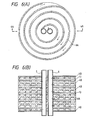
- Figs. 6(A) and 6(B) show a cell stack adopting a modified design of guide vanes 8A.
- Fig. 6(A) is a plan view and Fig. 6(A) is a cross section as viewed in the direction indicated by arrow 6A-6A in Fig. 6(A).
- the guide vanes 8A are formed as spiral coils. The pitch between adjacent turns of the spiral is selected at an optimum value which depends upon the diameter of the cell stack.
- the major advantage of this design is that the reactant gases can be admitted uniformly into the single cells 13 and that the discharged gases can be collected in one place.
- Fig. 7 shows a cross-section of a cell stack adopting a modified design of a gas seal.
- Each of the single cells 13 has an anode 2 and cathode 3 superposed on a circular solid electrolyte 1 and can be stacked alternately on circular separator plates 4B.
- a fuel gas supply manifold 5 and an oxidant gas supply manifold 6, which are both reactant gas pipes, are provided through the cell stack.
- a fuel gas discharge manifold and an oxidant gas discharge manifold, which make another pair of reactant gas pipes, are also provided through the cell stack but are not shown in Fig. 7.
- the anode 2 of each single cell is provided with a glass reservoir 16A, in which a glass O-ring 12B is fitted.
- the cathode 3 of each single cell is provided with a projection 15A.
- a glass reservoir 16B is formed on the upper surface of each separator plate 4B whereas a projection 15B is formed on its lower surface.
- a solid electrolyte fuel cell of the design described above may be fabricated by the following procedures.
- the circular solid electrolyte 1 (100 - 500 mim thick) is formed from yttria-stabilized zirconia.
- the solid electrolyte 1 has through-holes for insertion of the fuel gas supply manifold, oxidant gas supply manifold, fuel gas discharge manifold, and oxidant gas discharge manifold.
- a Ni-ZrO2 cermet is thermal-sprayed onto one principal surface of the solid electrolyte 1 to form a porous anode 2 in a thickness of 100 mim.
- Lanthanum manganite is sputtered onto the other principal surface of the solid electrolyte 1 to form a porous cathode 3 in a thickness of 50 - 200 mim.
- Glass reservoir 16A which resembles a gasket in shape and has a groove for storing glass, is press molded from a Ni-ZrO2 cermet and fired at a temperature of 1,000°C.
- the separator plates 4B are press molded from lanthanum chromite into a form having not only through-holes for insertion of a fuel gas supply manifold and the other necessary manifolds but also glass reservoir 16B and projection 15B. The molding is then fired to form a dense structure.
- Glass O-rings 12B and 12C are fitted in glass reservoirs 16A and 16B, respectively.
- the O-rings are formed of a soda lime glass having a melting point of 900°C and a working temperature of 1,000°C.
- the single cells 13 are alternately superposed on the separator plates 4B and the fuel gas supply manifold and the other necessary manifolds are set within the through-holes.
- the operating temperature of the fuel cell is maintained at 1,000°C for a sufficient duration of time to have the glass reservoir 16A and projection 15A baked to the anode 2 and cathode 3, respectively, of each single cell.
- the glass O-rings 12B and 12C are fused to enable liquid sealing.
- the fuel and oxidant gases that have undergone the reaction are discharged through the associated discharge manifolds (not shown). The discharged gases are not burnt around the cell stack, but instead are reacted within an isolated combustion chamber.
- the glass from which the O-rings are made solidifies but the soda lime glass having a greater linear expansion coefficient than zirconia and other electrode materials represents such a relatively small portion of the space in the glass reservoirs 16A and 16B that it will not cause cracking damage in the other components of the cell.
- Fig. 8 shows a cross section of a cell stack adopting another modification of the gas seal.
- gas sealing need not be effected around the cell stack.
- the discharged gases are burnt around the cell stack.
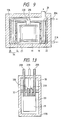
- FIG. 9 shows a cross-section of a solid electrolyte fuel cell having a combustion chamber according to a third example of the present invention.
- the combustion chamber 34 is provided around the cell stack.
- a natural gas (fuel gas) and steam are introduced from a pipe 20A and proceed down a fuel reformer 22, make a U-turn at the bottom, ascend to the top and enter a cell stack 19 via another fuel gas inlet pipe 20B.
- the natural gas is heated in a preheating chamber 25 and reformed to hydrogen, CO, and CO2 with the aid of the catalyst in the fuel reformer.
- the temperature suitable for reforming is within the range 700-850°C, so that satisfactory reforming can be accomplished with the discharged gases or combustion gases from the fuel cell of the present invention which operates in the temperature range of 900 -1,000°C.
- Air as an oxidant gas, flows spirally around the fuel reformed by passing through a route that starts with an oxidant gas inlet pipe 21A and ends with another oxidant gas inlet pipe 21B and in this process, the air is preheated to a temperature close to the operating temperature of the cell and introduced into the cell from above the central portion of the cell stack 19.
- the respective reaction gases react with each other within the cell stack and the unreacted hydrogen and oxygen, together with the product water, are discharged into a flame chamber 24 that surrounds the cell stack.
- the discharged H2, O2 and M2O mix in the flame chamber 24 and are burnt to form a combustion flame 23.
- a flame barrier 18 is disposed in such a way that the fuel reformer 22 will not be directly heated with the flame.
- the flame barrier 18 has small holes in it to provide a minimum barrier against heat.
- the combustion gases i.e., steam, carbon dioxide and nitrogen, are cooled in the preheating chamber 25 and recovered from the cell stack through a discharged gas vent 26. Even after being cooled in the preheating chamber 25, the discharged gases are still hot enough so that they may be utilized to produce lukewarm water.
- the vessel of the fuel reformer and the oxidant gas inlet pipes 21A and 21B may suitably be formed of a heat resistant alloy such as Incoloy 800H, whereas the flame barrier 18, may suitably be formed of a thin refractory brick or alumina.
- the cell stack 19, flame chamber 24, flame barrier 18 and preheating chamber are encased in a heat insulator 17A.
- Figs. 10(A) and 10(B) show a solid electrolyte fuel cell adopting a modified design of combustion chamber.
- Fig. 10(A) is a cross section and Fig. 10(B) is a plan view as seen in the direction indicated by arrow 10A-10A in Fig. 10(A).
- the fuel gas inlet pipe 20A and the oxidant gas inlet pipe 21A are heated in the preheating chamber 25.
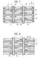
- Figs. 11(A) and 11(B) show a porous substrate 11C with a separator membrane for integration in a cell stack according to a fourth example of the present invention.
- Fig. 11(A) is a plan view and Fig. 11(B) is a cross section as viewed in the direction indicated by arrow 11A and 11A in Fig. 11(A).
- the porous substrate 11C has oxidant gas supply manifolds 6 and fuel gas supply manifolds 5 which are formed in the four corners of the substrate, as well as a fuel gas discharge manifold 27 and an oxidant gas discharge manifold 28 which are both formed in the central area of the substrate.
- the substrate is also provided with ribbed guide vanes 8A for directing the oxidant gas from the central area of the substrate to its peripheral area, and a ribbed guide vane 8B for providing a gas seal.
- the constituent materials of the separator 4C and porous substrate 11C and the processes for fabricating them are essentially the same as those described in connection with the porous substrate 11A with a separator membrane shown in Fig. 1.
- Figs. 12(A) and 12(B) show a porous substrate with a single cell for integration in a cell stack according to the fourth example of the prevention invention.
- Fig. 12(A) is a plan view and Fig. 12(B) is a cross-section as viewed in the direction indicated by arrow 12A-12A in Fig. 12(A).
- the constituent materials of the single cell 13 and porous substrate 11D and the processes for fabricating them are essentially the same as those described in connection with the porous substrate 11B with a single cell shown in Fig. 2.
- porous substrate 11C with a separator membrane and the porous substrate 11D with a single cell are alternately superposed one on another to form a cell stack 19 as shown in Fig. 13.
- Fig. 13 is a partial longitudinal section of a solid electrolyte fuel cell having a combustion chamber according to a fifth example of the present invention.
- the fuel gas passes through a fuel gas inlet pipe 20B, the fuel gas supply manifold 5 shown in Figs. 11(A) and 12(A), the fuel gas discharge manifold 27 shown in Figs. 11(A) and 12(A), and a fuel gas outlet pipe 31B.
- the oxidant gas passes through an oxidant gas inlet pipe 21B, the oxidant gas supply manifold 6 shown in Figs. 11(A) and 12(A), the oxidant gas discharge manifold 28 shown in Figs. 11(A) and 12(A), and an oxidant gas outlet pipe 31A.
- the discharged gases are burnt in a combination chamber 30.
- the heat of combustion is used to heat the fuel gas inlet pipe and the oxidant gas inlet pipe so as to preheat the reaction gases flowing through these pipes.
- the combustion chamber 30 is isolated from a stacking compartment 33 by a fire retarding wall 32.
- the combustion chamber 30 and the stacking compartment 33 are encased in a heat insulator 17B.
- the reactant gases are preheated before they are admitted into the stack 19 and this is effective in preventing thermal failure from occurring in the ceramic materials of which the fuel cell is made.
- the temperature of the single cells in the fuel cell system is maintained at a predetermined high level to improve its characteristics.
Abstract
Description
- The present invention relates to a solid electrolyte fuel cell that converts the free energy of a solid electrolyte to electrical energy by an electrochemical reaction and, in particular, to the reliability, operating characteristics and thermal efficiency of such a cell.
- Conventional power generators which employ heat engines such as gas turbines and diesel engines are subject to Carnot cycle efficiency limits. In contrast, the efficiency of fuel cells is dependent on the relationship between the change in the free energy of the underlying electrochemical reaction and the enthalpy of that reaction, and hence is expected to be higher than the efficiency of conventional power generators. Because of this advantage, the use of fuel cells as power generators will contribute to efficient utilization of resources and to a relative decrease in the level of CO₂ emissions and an extremely low level of NOx emissions. Fuel cells therefore hold much promise as a powerful means for curbing the aggravation of the environment by air pollution.
- A fuel cell consists of an electrolyte plate sandwiched between two electrodes, the oxygen electrode (cathode) and the fuel electrode (anode). Oxygen or air is supplied to the oxygen electrode whereas hydrogen, a reformed gas obtained by reforming (or processing) hydrocarbons such as natural gas, methanol and petroleum, or coal gas is supplied to the fuel electrode. The supplied oxygen combines electrochemically with the hydrogen in the fuel to produce both electricity and water. Fuel cells can be classified by electrolyte and the four predominant types developed so far comprise alkali electrolyte fuel cells, phosphoric acid electrolyte fuel cells, molten carbonate electrolyte fuel cells, and solid electrolyte fuel cells. Solid electrolyte fuel cells make use of solid oxides and are operated at temperatures of 900 - 1,000°C.
- In a solid electrolyte fuel cell, oxygen ions (0²⁻) migrate through a porous ceramic electrolyte such as yttria stabilized zirconia (ZrO₂-Y₂O₃).
The reaction occurring at the oxygen electrode is:
1/20₂ + 2e⁻ = O²⁻ (1).
The reaction taking place at the fuel electrode are:
H₂ + O²⁻ = H₂O + 2e⁻ (2)
CO +O²⁻ = CO₂ + 2e⁻ (3).
The overall reactions in the cell are:
1/20₂ + H₂ = H₂O (4)
1/20₂ + CO = CO₂ (5).
One major advantage of solid electrolyte fuel cells is that CO can be directly used as a fuel as it would be in the case of molten carbonate electrolyte fuel cells, so that reformed gases obtained by reforming hydrocarbon fuels such as natural gas, methanol and petroleum can be directly supplied to the cell without being passed through a CO converter. Even the fuel reformer (or processor) can be eliminated since the high operating temperature (1,000°C) combined with the use of Ni as the fuel electrode material enables the fuel gas to be reformed within the cell. This feature offers the added advantage that the fuel supply system for solid electrolyte fuel cells is much simpler in construction than those for other types of fuel cells. Furthermore, the temperature of the gas discharged from solid electrolyte fuel cells is high enough to expand the scope of applications of the heat of the exhaust gases. - The structure of single cells in solid electrolyte fuel cells may be roughly divided into two types. One is a cylindrical type that is described in U.S. Patent No. 3,460,991, or in the 1983 National Fuel Cell Seminar, Nov. 13-16, 1983, Oakland, Florida, p. 78 and/ or in 1985 Fuel Cell Seminar, May 19-22, 1985, Tucson, Arizona, p. 95. The other type is a flat or planar one that is described in U.S. Patent No. 3,554,808, or U.S. Patent No. 4,490,445 or 1983 National Fuel Cell Seminar, ibid., p. 74. Solid electrolyte fuel cells which are basically composed of ceramic materials are mechanically brittle and are prone to failure on account of the thermal stress that would be produced by thermal expansion mismatch and nonuniformity in power generation by the cell. These problems have long prevented the development of practically feasible models of solid electrolyte fuel cells. However, as the above-cited U.S. patents show, electrode and separator materials having thermal expansion coefficients substantially the same as those of electrolyte materials were discovered and this led to the fabrication of experimental cells and the conducting of power generation tests on these cells. In particular, the cell system described in 1983 National Fuel Cell Seminar, No. 13-16, 1983, Oakland, Florida, p. 78, is designed for circumventing thermal expansion and provides higher reliability for single cells. However, the individual cells in this system are connected by a nickel felt pad which is not capable of complete thermal expansion absorption. In addition, current will flow along the surfaces of thin electrodes and the resulting increase in resistance (ohmic) loss will lead to lower power densities.
- Among the planar type cells proposed to date, the one reported in 1983 National Fuel Cell Seminar Nov. 13-16, Oakland, Florida, p. 74, is of a monolithic design constructed by sintering an assembly of an electrolyte, electrodes and a separator and features the ability to produce an extremely high output power density. However, not only does this system require a sophis fabricating technique but it also is substantially incapable of circumventing thermal expansion, thus making it impossible to fabricate a device of large size. In other words, a limited scope of utility is the major defect of this cell design. The fuel cell described in U.S. Patent No. 4,490,445 comprises single cells which are held between ribbed separator plates and which are each fabricated by sintering an assembly of electrodes (0.003 - 0.005 inch) coated on opposite sides of a thin disk (0.01 - 0.02 inch) of ZrO₂-Y₂O₃ which serves as an electrolyte. In the absence of a tight gas seal, this cell design is capable of circumventing the thermal expansion of individual cells.
- However, in the fuel cell described above, the reactant gases flow diametrically along the principal surfaces of single cells, so the travel path of the reactant gases tends to become longer and the resulting increase in their concentration gradient leads to a greater degree of nonuniformity in the cell output distribution on the cell surfaces.
- An object of the present invention is a solid electrolyte fuel cell in which the individual components are adapted to be freely slidable with respect to one another and the travel path of reactant gases is made sufficiently short to circumvent thermal failure of the cell components in the face of temperature changes encountered by the fuel cell, thereby ensuring improved reliability and operating characteristics.
- Another object of the present invention is to provide a solid electrolyte fuel cell that insures improved thermal efficiency by making use of the heat of combustion of the gas to be discharged from the cell.
- The above-stated objects and other objects of the present invention are attained by a solid electrolyte fuel cell comprising planar single cells each having a cathode and an anode disposed on the two principal surfaces of a solid electrolyte substrate and having superposed thereon reactant gas distributing means for supplying individually two reactant gases, an oxidant gas and a fuel gas, to the two electrodes of each single cell, characterized in that the fuel cell includes reactant gas distributing means having guide vanes for directing the reactant gases into the space between the central and peripheral portions and for establishing electrical connection to the single cells, and manifolds penetrating through the central area of the superposed single cells and reactant gas distributing means to permit the parallel flows of reactant gases to be supplied to or discharged from the anode and cathode of each single cell.
- Another embodiment of the present invention comprises reactant gas distributing means that having guide vanes for directing the reactant gases into the space between the central and peripheral portions and for establishing electrical connection to the single cells and also having a reactant gas discharge slit in the peripheral portion for allowing the reactant gases to be discharged manifolds penetrating through the central area of the superposed single cells and reactant gas distributing means and to permit the parallel flows of reactant gases to be supplied to the anode and cathode of each single cell, a flame barrier disposed around a cell stack comprising the superposed single cells and reactant gas distributing means for blocking a combustion flame if such is generated around the cell stack, and a heat insulator that accommodates the cell stack and the flame barrier, with a preheating chamber being interposed.
- In still another embodiment, the fuel cell of the present invention includes reactant gas distributing means having guide vanes for directing the reactant gases into the space between the central and peripheral portions and for establishing electrical connection to the single cells and having a guide vane in the peripheral portion for sealing the reactant gases, manifolds that penetrate through the central area of the superposed single cells reactant gas distributing means to permit the parallel flows of reactant gases to be supplied to or discharged from the anode and cathode of each single cell and manifolds and to penetrate through the superposed single cells reactant gas distributing means in their peripheral portion and inward of the reactant gas sealing guide vane, and a combustion chamber adjoining a stack chamber for accommodating the cell stack comprising the superposed single cells and reactant gas distributing means and being partitioned from the stack chamber by a flame retarding well.
- The single cells may be formed either as self-supporting thin sheets or as membranes that are supported on a substrate. Self-supporting single cells do not use a supporting substrate. The same applies to the reactant gas distributing means and they may be either a porous substrate having a separator plate or guide vanes which both are in the form of a self-supporting dense thin sheet, or a porous or dense substrate having a dense separator membrane on one principal surface and guide vanes on the other principal surface. The manofolds supply a fuel gas to the anode of each single cell or allow the fuel gas to be discharged after the reaction. Furthermore, the manifolds supply an oxidant gas to the cathode of each single cell or allow the oxidant gas to be discharged after the reaction. The manifolds may be formed of reactant gas pipes or alternatively, they may be formed by interconnecting reactant gas passage holes that are formed across the thickness of the superposed single cells and reactant gas distributing means. The guide vanes in the reactant gas distributing means allow the reactant gases to be displaced to the area between the central and peripheral portions of each single cell. The reactant gases may flow in various ways by following, for example, a linear, serpentine or spiral path. The gas sealing guide vane may be provided in the outer-most peripheral portion of the reactant gas distributing means in order to ensure that the reactant gases will not be discharged to the surroundings of the cell stack comprising the superposed single cells and reactant gas distributing means. If reactant gas discharge slits are provided, the reactant gases can be discharged to the surroundings of the cell stack. A gas seal need not be provided for the entire portion of the single cells and reactant gas distributing means and may instead be provided in selected areas by means of glass O-rings. Sealing may be provided by an adhesive for ceramics in place of glass O-rings. If the reactant gases are discharged to the surroundings of the cell stack, a combustion flame will develop in the flame chamber around the cell stack. In this case, the fuel gas reformer and the oxidant or reactant gas inlet pipe can be heated by making use of the heat of the combustion flame. If no reactant gases are to be discharged into the flame chamber around the cell stack, the discharged gases are collected by the manifolds and allowed to react in the combustion chamber isolated from the stack chamber.
- The reactant gases are directed by the reactant gas distributing means to flow between the central manifolds and the peripheral portion of the distributing means, and this obviates the need to provide an overall gas seal between the individual components of the fuel cell. A gas seal may be provided in selected areas near to the manifolds. The reactant gases flow between the central and peripheral portions of the reactant gas distributing means and this shorter travel path of the reactant gases effectively reduces the concentration gradient of these gases. The reactant gases discharged from the cell stack are burnt by reacting with each other either between the flame barrier and the cell stack or within the combustion chamber partitioned from the cell stack, and the resulting heat of combustion may be effectively used.
-
- Figs. 1(A) and 1(B) show a porous substrate with a separator membrane for integration in a cell stack according to a first example of the present invention, with Fig. 1(A) being a plan view and Fig. 1(B) being a cross section as viewed in the direction indicated by
arrow 1A-1A in Fig. 1(A); - Figs. 2(A) and (B) show a porous substrate with a single cell for integration in a cell stack according to the first example of the present invention, with Fig. 2(A) being a plan view and Fig. 2(B) being a cross section as viewed in the direction indicated by
arrow 2A-2A in Fig. 2(A); - Fig. 3 shows a cross-section of a cell stack according to the first example of the present invention;
- Figs. 4(A) and 4(B) are enlarged views of portion A of Fig. 3, with Fig. 4(A) being a cross-section showing the state before heating and Fig. 4(B) showing the state after heating;
- Figs. 5(A) and 5(B) show a cell stack according to a second example of the present invention, with Fig. 5(A) being a cross-section and Fig. 5(B) being a plan view as viewed in the direction indicated by
arrow 5A-5A in Fig. 5(A); - Figs 6 (A) and 6(B) show a cell stack adopting a modified design of guide vanes, with Fig. 6(A) being a plan view and Fig. 6(B) being a cross-section as viewed in the direction indicated by
arrow 6A-6A in Fig. 6(A); - Fig. 7 shows a cross-section of a cell stack adopting a modified design of gas seal;
- Fig. 8 shows a cross-section of a cell stack adopting another modification of gas seal;
- Fig. 9 shows a cross-section of a solid electrolyte fuel cell having a combustion chamber according to a third example of the present invention;
- Figs. 10(A) and 10(B) show a solid electrolyte fuel cell adopting a modified design of combustion chamber, with Fig. 10(A) being a cross-section; and Fig. 10(B) being a plan view as seen in the direction indicated by
arrow 10A-10A in Fig. 10(A); - Figs. 11(A) and 11(B) show a porous substrate with a separator membrane for integration in a cell stack according to a fourth example of the present invention, with Fig. 11(A) being a plain view and Fig. 11(B) being a cross-section as viewed in the direction indicated by the
arrow 11A-11A in Fig. 11(A); - Figs. 12(A) and 12(B) show a porous substrate with a single cell for integration in a cell stack according to the fourth example of the present invention, with Fig. 12(A) being a plan view and Fig. 12(B) being a cross-section as viewed in the direction indicated by
arrow 12A-12A in Fig. 12(A) and - Fig. 13 is a partial longitudinal section of a solid electrolyte fuel all having a combustion chamber according to a fifth example of the present invention.
- Examples of the present invention are described hereunder with reference to the accompanying drawings.
- Figs. 1(A) and 1(B) show a porous substrate with a separator membrane for integration in a cell stack according to a first example of the present invention. Fig. 1(A) is a plan view and Fig. 1(B) is a cross-section as viewed in the direction indicated by
arrow 1A-1A in Fig. 1(A). Theporous substrate 11A (reactant gas distributing means) is formed of lanthanum manganite (LcMnO₃). theseparator membrane 4A is formed of a dense lanthanum chromite (LaCrO₃) layer. Theseparator membrane 4A is also part of the reactant gas distributing means. Amanifold 6, through which an oxidant gas is supplied, and amanifold 5, through which a fuel gas is supplied, are provided as reactant gas passage holes in the central area of theporous substrate 11A with the separator membrane. Reactant gas supply slits 10A are formed in the oxidantgas supply manifold 6. Theporous substrate 11A is provided withribbed guide vanes 8A for directing the oxidant gas, slits 29 for radially guiding the oxidant gas, and a reactant gas discharge slit 14 through which the oxidant gas is to be discharged. Fitting around the ribs, which form the fuel gas supply manifold, is a gas sealing glass O-ring 12. - Figs. 2(A) and 2(B) show a porous substrate with a single cell for integration in a cell stack according to the first example of the present invention. Fig. 2(A) is a plan view and Fig. 2(B) is a cross-section as viewed in the direction indicated by
arrow 2A-2A in Fig. 2(A). Theporous substrate 11B (reactant gas distributing means) is formed from a nickel-zirconia (Ni -ZrO₂) cermet. Thesingle cell 13 is formed on theporous substrate 11B. Thesingle cell 13 is composed of asolid electrolyte 1 made of yttria (Y₂O₃) stabilized dense zirconia, ananode 2 made of a porous Ni-ZrO₂ cermet, and acathode 3 made of porous lanthanum manganite. An oxidantgas supply manifold 6 and a fuelgas supply manifold 5 are provided in the central area of theporous substrate 11B withsingle cell 13. Reactant gas supply slits 10B are formed in the fuelgas supply manifold 5. Theporous substrate 11B is furnished withribbed guide vanes 8A for directing the fuel gas, slits 29 for radially guiding the fuel gas, and reactant gas discharge slits 14 through which the fuel gas is to be discharged. Fitted around the ribs on the substrate which form the oxidantgas supply manifold 6 is a gas sealing glass O-ring 12. - The
porous substrate 11A equipped with a separator membrane may be fabricated by the following method: a porous substrate with ribbed guide vanes that measures 300 mm x 300 mm x 2 mm is provided, and lanthanum chromite is densely plasma sprayed onto a flat major surface of this substrate to form theseparator membrane 4A in a thickness of 40mim. Theporous substrate 11B equipped with a single cell may be fabricated by the following method: a porous substrate measuring 300 mm x 300 mm x 2 mm is provided, and a Ni-ZrO₂ cermet is loosely plasma sprayed onto a flat principal surface of this substrate to form theporous anode 2 in a thickness of 100 mim. Zirconia stabilized with yttria is thermal-sprayed onto theanode 2 to form the densesolid electrolyte 1 in a thickness of 30 mim. Subsequently, lanthanum manganite is plasma-sprayed to form theporous cathode 3 in a thickness of 800 mim. A dense, rather than porous, substrate may be fabricated using lanthanum manganite. In this case, too, a dense separator membrane formed of lanthanum chromite is necessary since lanthanum manganite is reduced in a reducing atmosphere. - Fig. 3 shows a cross section of a cell stack in which the
porous substrate 11A of Fig. 1(b) with a separator membrane and theporous substrate 11B of Fig. 2(b) with a single cell are alternately superposed one on another. Reactant gases are supplied through the reactantgas supply slits - Fig. 4 is an enlarged view of portion A of Fig. 3, Fig. 4(A) is a cross-section showing the state before heating, and Fig. 4(B) after heating. Upon heating, the glass O-
ring 12 is fused to provide a liquid seal. The ribs on the substrate around which the glass O-ring 12 is fitted have a filling or cloggingportion 34 formed of a ceramic cement or some other suitable material on their inner surfaces. - The oxidant gas is admitted into the
porous substrate 11A formed of lanthanum manganite. The oxidant gas, as guided by theguide vane 8A and slits 29, flows in a serpentine path toward the peripheral portion of thesubstrate 11A to be distributed to thecathode 3 of each single cell. The fuel gas, on the other hand, is admitted into theporous substrate 11B formed of a Ni-ZrO₂ cermet. The fuel gas flows in the same way as does the oxidant gas and is thus distributed to theanode 2 of each single cell. Theseparator membrane 4A prevents contact between the oxidant and fuel gases. The electromotive force (0.5 - 0.9 volts) generated in one single cell by an electrochemical reaction is added to the electromotive force generated in the other single cell connected in series to the first cell. Theporous substrate 11A made of lanthanum manganite, theseparator 4A made of lanthanum chromite and theporous substrate 11B made of a Ni-ZrO₂ cermet have electronic conductivity and permit a current to flow through a series circuit. - The
separator membrane 4A, which has been formed by thermal spraying, is joined physically to theporous substrate 11A and this allows the two members to slide freely on each other by thermal expansion or contraction. The same is true with the relationship between thesingle cell 13 and theporous substrate 11B, and with the relationship between theanode 2,solid electrolyte 1 andcathode 3 of which the single cell is composed. Even if theporous substrate 11A with a separator membrane is alternately superposed on theporous substrate 11B with a single cell to make a cell stack, theseparator membrane 4A (or single cell 13) and theporous substrate porous substrate 11A with a separator membrane on theporous substrate 11B with a single cell. The gas seal provided by the glass O-rings 12 is limited to selected areas in the neighborhood of the manifolds formed in theporous substrates separator 4A andsingle cell 13 are formed on substrates because in such a "support membrane system" the travel path of reactant gases becomes inevitably long in order to enable cell stacking over a large area. After the reaction, the reactant gases are discharged from the periphery of the cell stack and burnt. - Fig. 5 shows a cell stack according to a second example of the present invention. Fig. 5(a) is a cross-section and Fig. 5(b) is a plan view as seen in the direction indicated by arrows C in Fig. 5(a). A fuel gas (hydrogen) is introduced into a
separator plate 4B (reactant gas distributing means) by way of the fuelgas supply manifold 5. A reactant gas (oxygen) is introduced through the oxidantgas supply manifold 6 to be admitted into theseparator plate 4B which is a self-supporting thin plate. The oxidant gas and the fuel gas are separately directed to the two principal surfaces of theseparator plate 4B via reactant gas supply holes 10B. The reactant gas supply manifolds are reactant gas pipes that are made of zirconia stabilized with yttria (Y₂O₃). - The
separator plate 4B is made of lanthanum chromite (LaCrO₃) and sauntered densely to give a thickness of 0.5 - 2 mm. Lanthanum chromite has electronic conductivity and will not be oxidized even if it is placed in an oxidizing atmosphere. A further advantage of lanthanum chromite is that it shows a thermal expansion coefficient close to that of yttria-stabilized zirconia.Single cells 13 are connected in series by this lanthanum chromite.Guide vanes 8A are provided on the two principal surfaces of theseparator plate 4B. The guide vanes 8A direct the reactant gases to flow from the central area of theseparator plate 4B toward its peripheral area. The oxidant gas thus reaches thecathode 3 of each single cell whereas the fuel gas reaches theanode 2 of the single cell. - The
solid electrolyte 1 is a self-supporting thin plate having a thickness of 50 - 500 mim that is formed of yttria stabilised zirconia.Anode 2 andcathode 3 are baked to the two principal surfaces of thesolid electrolyte 1.Anode 2 is made of Ni-ZrO₂ and its thickness is selected from the range of 0.01 - 1 mm. Lanthanum manganite is used as the active material ofcathode 3. Both the anode and cathode are formed as porous structures. - A fuel cell with the construction described above has the advantage that the
single cells 13 andseparator plates 4B need not be provided with a gas seal and may be simply stacked alternately one on another. This permits thesingle cells 13 to freely slide on theseparator plates 4B during thermal expansion without developing any thermal stress. The gaps left between each of the reactantgas supply manifolds single cells 13 andseparator plate 4B may be filled by providingseal walls 9 on theseparator plates 4B and by forming aceramic sealing portion 7 between theseal walls 9 and each of the reactiongas supply manifolds portion 7 is so small that the thermal stress to be developed by the overall system will remain small. The reactant gases reaching the peripheral portion of the reactant gas distributing means are combusted in the sealingportion 7 to ensure that the temperature of the fuel cell is maintained at a predetermined high level. - The single cells as shown in Fig. 5 are of a disk shape but they may be otherwise shaped such as rectangular. The guide vanes 8A may also be designed in such a way that maximum cell characteristics can be attained by taking the concentration gradient of reactant gases into account.
- The reactant
gas supply manifolds - Figs. 6(A) and 6(B) show a cell stack adopting a modified design of
guide vanes 8A. Fig. 6(A) is a plan view and Fig. 6(A) is a cross section as viewed in the direction indicated byarrow 6A-6A in Fig. 6(A). The guide vanes 8A are formed as spiral coils. The pitch between adjacent turns of the spiral is selected at an optimum value which depends upon the diameter of the cell stack. The major advantage of this design is that the reactant gases can be admitted uniformly into thesingle cells 13 and that the discharged gases can be collected in one place. - Fig. 7 shows a cross-section of a cell stack adopting a modified design of a gas seal. Each of the
single cells 13 has ananode 2 andcathode 3 superposed on a circularsolid electrolyte 1 and can be stacked alternately oncircular separator plates 4B. A fuelgas supply manifold 5 and an oxidantgas supply manifold 6, which are both reactant gas pipes, are provided through the cell stack. A fuel gas discharge manifold and an oxidant gas discharge manifold, which make another pair of reactant gas pipes, are also provided through the cell stack but are not shown in Fig. 7. - The
anode 2 of each single cell is provided with aglass reservoir 16A, in which a glass O-ring 12B is fitted. Thecathode 3 of each single cell is provided with aprojection 15A. Aglass reservoir 16B is formed on the upper surface of eachseparator plate 4B whereas aprojection 15B is formed on its lower surface. - A solid electrolyte fuel cell of the design described above may be fabricated by the following procedures. First, the circular solid electrolyte 1 (100 - 500 mim thick) is formed from yttria-stabilized zirconia. The
solid electrolyte 1 has through-holes for insertion of the fuel gas supply manifold, oxidant gas supply manifold, fuel gas discharge manifold, and oxidant gas discharge manifold. A Ni-ZrO₂ cermet is thermal-sprayed onto one principal surface of thesolid electrolyte 1 to form aporous anode 2 in a thickness of 100 mim. Lanthanum manganite is sputtered onto the other principal surface of thesolid electrolyte 1 to form aporous cathode 3 in a thickness of 50 - 200 mim.Glass reservoir 16A, which resembles a gasket in shape and has a groove for storing glass, is press molded from a Ni-ZrO₂ cermet and fired at a temperature of 1,000°C. Theseparator plates 4B are press molded from lanthanum chromite into a form having not only through-holes for insertion of a fuel gas supply manifold and the other necessary manifolds but alsoglass reservoir 16B andprojection 15B. The molding is then fired to form a dense structure. - Glass O-
rings glass reservoirs single cells 13 are alternately superposed on theseparator plates 4B and the fuel gas supply manifold and the other necessary manifolds are set within the through-holes. The operating temperature of the fuel cell is maintained at 1,000°C for a sufficient duration of time to have theglass reservoir 16A andprojection 15A baked to theanode 2 andcathode 3, respectively, of each single cell. The glass O-rings - When the cell operation ends, the glass from which the O-rings are made solidifies but the soda lime glass having a greater linear expansion coefficient than zirconia and other electrode materials represents such a relatively small portion of the space in the
glass reservoirs - Fig. 8 shows a cross section of a cell stack adopting another modification of the gas seal. In the absence of reactant gas discharge manifolds, gas sealing need not be effected around the cell stack. The discharged gases are burnt around the cell stack.
- FIG. 9 shows a cross-section of a solid electrolyte fuel cell having a combustion chamber according to a third example of the present invention. The
combustion chamber 34 is provided around the cell stack. A natural gas (fuel gas) and steam are introduced from apipe 20A and proceed down afuel reformer 22, make a U-turn at the bottom, ascend to the top and enter acell stack 19 via another fuelgas inlet pipe 20B. In this process, the natural gas is heated in a preheatingchamber 25 and reformed to hydrogen, CO, and CO₂ with the aid of the catalyst in the fuel reformer. The temperature suitable for reforming is within the range 700-850°C, so that satisfactory reforming can be accomplished with the discharged gases or combustion gases from the fuel cell of the present invention which operates in the temperature range of 900 -1,000°C. Air, as an oxidant gas, flows spirally around the fuel reformed by passing through a route that starts with an oxidantgas inlet pipe 21A and ends with another oxidantgas inlet pipe 21B and in this process, the air is preheated to a temperature close to the operating temperature of the cell and introduced into the cell from above the central portion of thecell stack 19. - The respective reaction gases react with each other within the cell stack and the unreacted hydrogen and oxygen, together with the product water, are discharged into a
flame chamber 24 that surrounds the cell stack. The discharged H₂, O₂ and M₂O mix in theflame chamber 24 and are burnt to form acombustion flame 23. Aflame barrier 18 is disposed in such a way that thefuel reformer 22 will not be directly heated with the flame. On the other hand, theflame barrier 18 has small holes in it to provide a minimum barrier against heat. The combustion gases, i.e., steam, carbon dioxide and nitrogen, are cooled in the preheatingchamber 25 and recovered from the cell stack through a dischargedgas vent 26. Even after being cooled in the preheatingchamber 25, the discharged gases are still hot enough so that they may be utilized to produce lukewarm water. - The vessel of the fuel reformer and the oxidant
gas inlet pipes flame barrier 18, may suitably be formed of a thin refractory brick or alumina. Thecell stack 19,flame chamber 24,flame barrier 18 and preheating chamber are encased in aheat insulator 17A. - Figs. 10(A) and 10(B) show a solid electrolyte fuel cell adopting a modified design of combustion chamber. Fig. 10(A) is a cross section and Fig. 10(B) is a plan view as seen in the direction indicated by
arrow 10A-10A in Fig. 10(A). The fuelgas inlet pipe 20A and the oxidantgas inlet pipe 21A are heated in the preheatingchamber 25. - Figs. 11(A) and 11(B) show a
porous substrate 11C with a separator membrane for integration in a cell stack according to a fourth example of the present invention. Fig. 11(A) is a plan view and Fig. 11(B) is a cross section as viewed in the direction indicated byarrow porous substrate 11C has oxidantgas supply manifolds 6 and fuelgas supply manifolds 5 which are formed in the four corners of the substrate, as well as a fuelgas discharge manifold 27 and an oxidantgas discharge manifold 28 which are both formed in the central area of the substrate. The substrate is also provided withribbed guide vanes 8A for directing the oxidant gas from the central area of the substrate to its peripheral area, and aribbed guide vane 8B for providing a gas seal. The constituent materials of theseparator 4C andporous substrate 11C and the processes for fabricating them are essentially the same as those described in connection with theporous substrate 11A with a separator membrane shown in Fig. 1. - Figs. 12(A) and 12(B) show a porous substrate with a single cell for integration in a cell stack according to the fourth example of the prevention invention. Fig. 12(A) is a plan view and Fig. 12(B) is a cross-section as viewed in the direction indicated by
arrow 12A-12A in Fig. 12(A). The constituent materials of thesingle cell 13 andporous substrate 11D and the processes for fabricating them are essentially the same as those described in connection with theporous substrate 11B with a single cell shown in Fig. 2. - The
porous substrate 11C with a separator membrane and theporous substrate 11D with a single cell are alternately superposed one on another to form acell stack 19 as shown in Fig. 13. - Fig. 13 is a partial longitudinal section of a solid electrolyte fuel cell having a combustion chamber according to a fifth example of the present invention. The fuel gas passes through a fuel
gas inlet pipe 20B, the fuelgas supply manifold 5 shown in Figs. 11(A) and 12(A), the fuelgas discharge manifold 27 shown in Figs. 11(A) and 12(A), and a fuelgas outlet pipe 31B. The oxidant gas passes through an oxidantgas inlet pipe 21B, the oxidantgas supply manifold 6 shown in Figs. 11(A) and 12(A), the oxidantgas discharge manifold 28 shown in Figs. 11(A) and 12(A), and an oxidantgas outlet pipe 31A. - The discharged gases are burnt in a
combination chamber 30. The heat of combustion is used to heat the fuel gas inlet pipe and the oxidant gas inlet pipe so as to preheat the reaction gases flowing through these pipes. Thecombustion chamber 30 is isolated from a stackingcompartment 33 by afire retarding wall 32. Thecombustion chamber 30 and the stackingcompartment 33 are encased in aheat insulator 17B. The reactant gases are preheated before they are admitted into thestack 19 and this is effective in preventing thermal failure from occurring in the ceramic materials of which the fuel cell is made. In addition, the temperature of the single cells in the fuel cell system is maintained at a predetermined high level to improve its characteristics.
Claims (19)
(1) the reactant gas distributing means having guide vanes adapted to direct the reactant gases into the space between respective central and peripheral portions of each single cell and also a reactant gas discharge slit in the peripheral portion for allowing the reactant gases to be discharged, said distributing means comprising means for establishing electrical connection to the single cells;
and the fuel cell also comprises
(2) manifolds which penetrate the superposed single cells and reactant gas distributing means to supply the flows of reactant gases to, and to exhaust reactant gases from, the reactant gas distributing means;
(3) a flame barrier that is disposed around the superposed single cells except for portions of said manifolds to block a combustion flame that is generated from the reactant gases exhausted from said reactant gas distributing means; and
(4) a heat insulator that accommodates all of said fuel cell, including said flame barrier and forms a preheating chamber about said excepted portions of said manifolds.
(1) the reactant gas distributing means comprises guide vane means for directing the reactant gases into the space between respective central and peripheral portions of each single cell and comprises means for establishing electrical connection to the single cells, the guide vane means including guide vane means in the peripheral portion for sealing the reactant gases; said fuel cell further comprising
(2) manifolds that penetrate through the superposed single cells and reactant gas distributing means to supply and discharge the flows of reactant gases to and from the distributing means inward of the reactant gas sealing guide vane means; and
(3) a combustion chamber for combusting the discharged reactant gases, said combustion chamber comprising a flame retardant wall partitioning the superposed single cells therefrom.
Applications Claiming Priority (16)
| Application Number | Priority Date | Filing Date | Title |
|---|---|---|---|
| JP184132/88 | 1988-07-23 | ||
| JP18413288 | 1988-07-23 | ||
| JP20789888 | 1988-08-22 | ||
| JP207898/88 | 1988-08-22 | ||
| JP221545/88 | 1988-09-05 | ||
| JP22154588 | 1988-09-05 | ||
| JP27653288 | 1988-11-01 | ||
| JP276532/88 | 1988-11-01 | ||
| JP92736/89 | 1989-04-12 | ||
| JP9273689 | 1989-04-12 | ||
| JP118302/89 | 1989-05-11 | ||
| JP11830289 | 1989-05-11 | ||
| JP1135610A JPH02168568A (en) | 1988-09-05 | 1989-05-29 | Fuel battery with solid electrolyte |
| JP135610/89 | 1989-05-29 | ||
| JP147291/89 | 1989-06-08 | ||
| JP1147291A JP2555731B2 (en) | 1988-07-23 | 1989-06-08 | Solid oxide fuel cell |
Publications (2)
| Publication Number | Publication Date |
|---|---|
| EP0355420A1 true EP0355420A1 (en) | 1990-02-28 |
| EP0355420B1 EP0355420B1 (en) | 1993-10-06 |
Family
ID=27572865
Family Applications (1)
| Application Number | Title | Priority Date | Filing Date |
|---|---|---|---|
| EP89113437A Expired - Lifetime EP0355420B1 (en) | 1988-07-23 | 1989-07-21 | Solid electrolyte fuel cell |
Country Status (2)
| Country | Link |
|---|---|
| EP (1) | EP0355420B1 (en) |
| DE (1) | DE68909720T2 (en) |
Cited By (31)
| Publication number | Priority date | Publication date | Assignee | Title |
|---|---|---|---|---|
| EP0374636A1 (en) * | 1988-12-20 | 1990-06-27 | Asea Brown Boveri Ag | Process for the conversion of the chemical potential energy of a material into electrical energy by a high-temperature electrochemical process |
| EP0397072A1 (en) * | 1989-05-12 | 1990-11-14 | Asea Brown Boveri Ag | Arrangement of a plurality of flat, even, high-temperature fuel cells, assembled in a stack |
| EP0426265A2 (en) * | 1989-09-12 | 1991-05-08 | Mitsubishi Jukogyo Kabushiki Kaisha | Solid electrolyte fuel cell |
| EP0450336A2 (en) * | 1990-03-13 | 1991-10-09 | Mitsubishi Jukogyo Kabushiki Kaisha | Power generation system with flat fuel cells of solid electrolyte |
| WO1992006517A1 (en) * | 1990-10-05 | 1992-04-16 | Seed Capital Investments (Sci) B.V. | Seals for gas-carrying lines and installations which comprise such seals |
| EP0510584A1 (en) * | 1991-04-23 | 1992-10-28 | Osaka Gas Co., Ltd. | Method of producing interconnectors for solid oxide electrolyte fuel cells |
| EP0568991A1 (en) * | 1992-05-08 | 1993-11-10 | Osaka Gas Co., Ltd. | Solid-electrolyte fuel cell system |
| EP0580918A1 (en) * | 1992-07-27 | 1994-02-02 | Sulzer Innotec Ag | Device comprising high-temperature fuel cells |
| DE4236441A1 (en) * | 1992-10-28 | 1994-05-05 | Siemens Ag | Sealing gas spaces in a height temperature fuel cell - treating spaces with at least two gases in succession, first containing oxidisable compound, others being acidic |
| WO1994010717A1 (en) * | 1992-10-28 | 1994-05-11 | Siemens Aktiengesellschaft | Process for sealing high-temperature fuel cells and fuel cells sealed according to this process |
| EP0654838A1 (en) * | 1993-11-24 | 1995-05-24 | Sulzer Innotec Ag | Device comprising high-temperature fuel cells and method of starting said device |
| WO1995026430A2 (en) * | 1994-03-21 | 1995-10-05 | Ztek Corporation | Electrochemical converter having optimal pressure distribution |
| WO1996008052A1 (en) * | 1994-09-03 | 1996-03-14 | Forschungszentrum Jülich GmbH | Solid electrolyte, high temperature fuel cell arrangement |
| WO1997027639A1 (en) * | 1996-01-22 | 1997-07-31 | Alliedsignal Inc. | Coflow planar fuel cell stack construction for solid electrolytes |
| US6054229A (en) * | 1996-07-19 | 2000-04-25 | Ztek Corporation | System for electric generation, heating, cooling, and ventilation |
| EP1037296A1 (en) * | 1999-03-17 | 2000-09-20 | Sulzer Hexis AG | Fuel cell stack with exhaust gases after-burning region at the periphery of the stack |
| US6344290B1 (en) | 1997-02-11 | 2002-02-05 | Fucellco, Incorporated | Fuel cell stack with solid electrolytes and their arrangement |
| US6361892B1 (en) | 1999-12-06 | 2002-03-26 | Technology Management, Inc. | Electrochemical apparatus with reactant micro-channels |
| US6399233B1 (en) | 1999-07-29 | 2002-06-04 | Technology Management, Inc. | Technique for rapid cured electrochemical apparatus component fabrication |
| WO2004021492A1 (en) * | 2002-08-28 | 2004-03-11 | Honda Giken Kogyo Kabushiki Kaisha | Bipolar plates assembly for a fuel cell |
| EP1433767A1 (en) * | 2001-09-26 | 2004-06-30 | Ngk Insulators, Ltd. | Laminated ceramic sintered compact, method for producing laminated ceramic sintered compact, electrochemical cell, electroconductive joining member for electrochemical cell, and electrochemical device |
| WO2006116638A2 (en) | 2005-04-27 | 2006-11-02 | Lilliputian Systems Inc. | Compact solid oxide fuel cell apparatus |
| DE102005021487A1 (en) * | 2005-05-10 | 2006-11-16 | Bohmann, Dirk, Dr.-Ing. | Metallic bipolar plates for use in fuel cell stacks are produced by forming metal foil with channels on both sides |
| DE102005026060A1 (en) * | 2005-05-18 | 2006-11-23 | Bohmann, Dirk, Dr.-Ing. | Bipolar plate for proton exchange membrane fuel cell stack has spiral or meander channels in crossing region ending in outer inlet pockets formed in same directions as alternately forward and rearward channels |
| EP1786055A1 (en) * | 2005-10-25 | 2007-05-16 | General Electric Company | SOFC seal and cell thermal management |
| WO2007074666A1 (en) * | 2005-12-28 | 2007-07-05 | Honda Motor Co., Ltd. | Fuel cell and fuel cell stack |
| EP1852929A1 (en) * | 2005-02-22 | 2007-11-07 | Mitsubishi Materials Corporation | Solid oxide fuel cell |
| US7449261B2 (en) | 2001-09-13 | 2008-11-11 | Ngk Insulators, Ltd. | Holding member for holding an electrochemical cell, a holding substrate for the same, an electrochemical system and a connecting member for electrochemical cells |
| US8043760B2 (en) | 2007-03-28 | 2011-10-25 | Ngk Insulators, Ltd. | Electrochemical cell stacks |
| WO2012097521A1 (en) * | 2011-01-21 | 2012-07-26 | 中国科学院宁波材料技术与工程研究所 | Solid oxide feul cell stack |
| CN111370726A (en) * | 2020-03-17 | 2020-07-03 | 山东建筑大学 | Radial flow field structure of fuel cell |
Families Citing this family (4)
| Publication number | Priority date | Publication date | Assignee | Title |
|---|---|---|---|---|
| GB2519494B (en) | 2012-08-14 | 2021-02-24 | Loop Energy Inc | Fuel cell flow channels and flow fields |
| US9644277B2 (en) | 2012-08-14 | 2017-05-09 | Loop Energy Inc. | Reactant flow channels for electrolyzer applications |
| WO2014026287A1 (en) | 2012-08-14 | 2014-02-20 | Powerdisc Development Corporation Ltd. | Fuel cell components, stacks and modular fuel cell systems |
| CN109075358B (en) | 2016-03-22 | 2021-10-19 | 环能源公司 | Fuel cell flow field design for thermal management |
Citations (9)
| Publication number | Priority date | Publication date | Assignee | Title |
|---|---|---|---|---|
| US3432353A (en) * | 1965-03-03 | 1969-03-11 | Asea Ab | Fuel cell electrode |
| GB1197496A (en) * | 1966-09-20 | 1970-07-08 | Bbc Brown Boveri & Cie | High-temperature fuel-cell battery |
| US3526548A (en) * | 1965-12-10 | 1970-09-01 | Comp Generale Electricite | Fuel cell electrodes |
| US3718506A (en) * | 1971-02-22 | 1973-02-27 | Bbc Brown Boveri & Cie | Fuel cell system for reacting hydrocarbons |
| FR2432774A1 (en) * | 1978-07-31 | 1980-02-29 | Inst Francais Du Petrole | Electrode for fuel cell with sealed compartments - has two surfaces defining shallow rectangular cavity |
| US4490445A (en) * | 1982-05-24 | 1984-12-25 | Massachusetts Institute Of Technology | Solid oxide electrochemical energy converter |
| WO1986006762A1 (en) * | 1985-05-17 | 1986-11-20 | Hsu Michael S | Electrochemical converters and combined cycle systems |
| US4644751A (en) * | 1985-03-14 | 1987-02-24 | Massachusetts Institute Of Technology | Integrated fuel-cell/steam plant for electrical generation |
| EP0289226A1 (en) * | 1987-04-28 | 1988-11-02 | The Standard Oil Company | Improved solid electrolyte fuel cell and assembly |
-
1989
- 1989-07-21 DE DE89113437T patent/DE68909720T2/en not_active Expired - Fee Related
- 1989-07-21 EP EP89113437A patent/EP0355420B1/en not_active Expired - Lifetime
Patent Citations (9)
| Publication number | Priority date | Publication date | Assignee | Title |
|---|---|---|---|---|
| US3432353A (en) * | 1965-03-03 | 1969-03-11 | Asea Ab | Fuel cell electrode |
| US3526548A (en) * | 1965-12-10 | 1970-09-01 | Comp Generale Electricite | Fuel cell electrodes |
| GB1197496A (en) * | 1966-09-20 | 1970-07-08 | Bbc Brown Boveri & Cie | High-temperature fuel-cell battery |
| US3718506A (en) * | 1971-02-22 | 1973-02-27 | Bbc Brown Boveri & Cie | Fuel cell system for reacting hydrocarbons |
| FR2432774A1 (en) * | 1978-07-31 | 1980-02-29 | Inst Francais Du Petrole | Electrode for fuel cell with sealed compartments - has two surfaces defining shallow rectangular cavity |
| US4490445A (en) * | 1982-05-24 | 1984-12-25 | Massachusetts Institute Of Technology | Solid oxide electrochemical energy converter |
| US4644751A (en) * | 1985-03-14 | 1987-02-24 | Massachusetts Institute Of Technology | Integrated fuel-cell/steam plant for electrical generation |
| WO1986006762A1 (en) * | 1985-05-17 | 1986-11-20 | Hsu Michael S | Electrochemical converters and combined cycle systems |
| EP0289226A1 (en) * | 1987-04-28 | 1988-11-02 | The Standard Oil Company | Improved solid electrolyte fuel cell and assembly |
Non-Patent Citations (3)
| Title |
|---|
| PATENT ABSTRACTS OF JAPAN, vol. 11, no. 306 (E-546)[2753], 6th October 1987; & JP-A-62 98 567 (HITACHI LTD) 08-05-1987 * |
| PATENT ABSTRACTS OF JAPAN, vol. 11, no. 83 (E-489)[2530], 13th March 1987; & JP-A-61 237 370 (ISHIKAWAJIMA HARIMA HEAVY IND. CO.) 22-10-1980 * |
| PATENT ABSTRACTS OF JAPAN, vol. 12, no. 273 (E-639)[3120], 29th July 1988; & JP-A-63 53 863 (MITSUBISHI HEAVY IND., LTD) 08-03-1988 * |
Cited By (58)
| Publication number | Priority date | Publication date | Assignee | Title |
|---|---|---|---|---|
| EP0374636A1 (en) * | 1988-12-20 | 1990-06-27 | Asea Brown Boveri Ag | Process for the conversion of the chemical potential energy of a material into electrical energy by a high-temperature electrochemical process |
| EP0397072A1 (en) * | 1989-05-12 | 1990-11-14 | Asea Brown Boveri Ag | Arrangement of a plurality of flat, even, high-temperature fuel cells, assembled in a stack |
| EP0426265A2 (en) * | 1989-09-12 | 1991-05-08 | Mitsubishi Jukogyo Kabushiki Kaisha | Solid electrolyte fuel cell |
| EP0426265A3 (en) * | 1989-09-12 | 1991-09-25 | Mitsubishi Jukogyo Kabushiki Kaisha | Solid electrolyte fuel cell |
| US5145753A (en) * | 1989-09-12 | 1992-09-08 | Mitsubishi Jukogyo Kabushiki Kaisha | Solid electrolyte fuel cell |
| AU634812B2 (en) * | 1989-09-12 | 1993-03-04 | Mitsubishi Jukogyo Kabushiki Kaisha | Solid electrolyte fuel cell |
| EP0450336A2 (en) * | 1990-03-13 | 1991-10-09 | Mitsubishi Jukogyo Kabushiki Kaisha | Power generation system with flat fuel cells of solid electrolyte |
| EP0450336A3 (en) * | 1990-03-13 | 1991-10-23 | Mitsubishi Jukogyo Kabushiki Kaisha | Power generation system with flat fuel cells of solid electrolyte |
| US5360681A (en) * | 1990-10-05 | 1994-11-01 | Seed Capital Investments (Sct) B.V. | Seals for gas-carrying lines and installations which comprise such seals |
| WO1992006517A1 (en) * | 1990-10-05 | 1992-04-16 | Seed Capital Investments (Sci) B.V. | Seals for gas-carrying lines and installations which comprise such seals |
| AU657445B2 (en) * | 1990-10-05 | 1995-03-09 | Seed Capital Investments (Sci) B.V. | Seals for gas-carrying lines and installations which comprise such seals |
| US5348776A (en) * | 1991-04-23 | 1994-09-20 | Osaka Gas Company Limited | Method of producing interconnectors for solid oxide electrolyte fuel cells |
| EP0510584A1 (en) * | 1991-04-23 | 1992-10-28 | Osaka Gas Co., Ltd. | Method of producing interconnectors for solid oxide electrolyte fuel cells |
| US5350642A (en) * | 1992-05-08 | 1994-09-27 | Osaka Gas Co., Ltd. | Solid-electrolyte fuel cell system |
| EP0568991A1 (en) * | 1992-05-08 | 1993-11-10 | Osaka Gas Co., Ltd. | Solid-electrolyte fuel cell system |
| EP0580918A1 (en) * | 1992-07-27 | 1994-02-02 | Sulzer Innotec Ag | Device comprising high-temperature fuel cells |
| US5532071A (en) * | 1992-10-28 | 1996-07-02 | Siemens Aktiengesellschaft | Process for sealing high-temperature fuel cells |
| WO1994010717A1 (en) * | 1992-10-28 | 1994-05-11 | Siemens Aktiengesellschaft | Process for sealing high-temperature fuel cells and fuel cells sealed according to this process |
| DE4331912A1 (en) * | 1992-10-28 | 1995-03-23 | Siemens Ag | Process for sealing high temperature fuel cells |
| DE4236441A1 (en) * | 1992-10-28 | 1994-05-05 | Siemens Ag | Sealing gas spaces in a height temperature fuel cell - treating spaces with at least two gases in succession, first containing oxidisable compound, others being acidic |
| EP0654838A1 (en) * | 1993-11-24 | 1995-05-24 | Sulzer Innotec Ag | Device comprising high-temperature fuel cells and method of starting said device |
| WO1995026430A2 (en) * | 1994-03-21 | 1995-10-05 | Ztek Corporation | Electrochemical converter having optimal pressure distribution |
| WO1995026430A3 (en) * | 1994-03-21 | 1996-02-08 | Ztek Corp | Electrochemical converter having optimal pressure distribution |
| US5833822A (en) * | 1994-03-21 | 1998-11-10 | Ztek Corporation | Electrochemical converter having optimal pressure distribution |
| WO1996008052A1 (en) * | 1994-09-03 | 1996-03-14 | Forschungszentrum Jülich GmbH | Solid electrolyte, high temperature fuel cell arrangement |
| WO1997027639A1 (en) * | 1996-01-22 | 1997-07-31 | Alliedsignal Inc. | Coflow planar fuel cell stack construction for solid electrolytes |
| US6054229A (en) * | 1996-07-19 | 2000-04-25 | Ztek Corporation | System for electric generation, heating, cooling, and ventilation |
| US6344290B1 (en) | 1997-02-11 | 2002-02-05 | Fucellco, Incorporated | Fuel cell stack with solid electrolytes and their arrangement |
| EP1037296A1 (en) * | 1999-03-17 | 2000-09-20 | Sulzer Hexis AG | Fuel cell stack with exhaust gases after-burning region at the periphery of the stack |
| US6432567B1 (en) | 1999-03-17 | 2002-08-13 | Sulzer Hexis Ag | Fuel cell battery with afterburning at the periphery of a cell stack |
| US6399233B1 (en) | 1999-07-29 | 2002-06-04 | Technology Management, Inc. | Technique for rapid cured electrochemical apparatus component fabrication |
| US6878480B2 (en) | 1999-12-06 | 2005-04-12 | Technology Management, Inc. | Electrochemical apparatus with reactant micro-channels |
| US6361892B1 (en) | 1999-12-06 | 2002-03-26 | Technology Management, Inc. | Electrochemical apparatus with reactant micro-channels |
| US7449261B2 (en) | 2001-09-13 | 2008-11-11 | Ngk Insulators, Ltd. | Holding member for holding an electrochemical cell, a holding substrate for the same, an electrochemical system and a connecting member for electrochemical cells |
| EP1433767A1 (en) * | 2001-09-26 | 2004-06-30 | Ngk Insulators, Ltd. | Laminated ceramic sintered compact, method for producing laminated ceramic sintered compact, electrochemical cell, electroconductive joining member for electrochemical cell, and electrochemical device |
| EP1433767A4 (en) * | 2001-09-26 | 2008-01-16 | Ngk Insulators Ltd | Laminated ceramic sintered compact, method for producing laminated ceramic sintered compact, electrochemical cell, electroconductive joining member for electrochemical cell, and electrochemical device |
| WO2004021492A1 (en) * | 2002-08-28 | 2004-03-11 | Honda Giken Kogyo Kabushiki Kaisha | Bipolar plates assembly for a fuel cell |
| US7049019B2 (en) | 2002-08-28 | 2006-05-23 | Honda Giken Kogyo Kabushiki Kaisha | Fuel cell |
| EP1852929A1 (en) * | 2005-02-22 | 2007-11-07 | Mitsubishi Materials Corporation | Solid oxide fuel cell |
| US8338047B2 (en) | 2005-02-22 | 2012-12-25 | Mitsubishi Materials Corporation | Solid oxide fuel cell |
| EP1852929A4 (en) * | 2005-02-22 | 2008-05-07 | Mitsubishi Materials Corp | Solid oxide fuel cell |
| WO2006116638A2 (en) | 2005-04-27 | 2006-11-02 | Lilliputian Systems Inc. | Compact solid oxide fuel cell apparatus |
| US7947407B2 (en) | 2005-04-27 | 2011-05-24 | Lilliputian Systems, Inc. | Fuel cell apparatus having a small package size |
| WO2006116638A3 (en) * | 2005-04-27 | 2007-05-24 | Lilliputian Systems Inc | Compact solid oxide fuel cell apparatus |
| DE102005021487B4 (en) * | 2005-05-10 | 2014-11-20 | Dirk Bohmann | Bipolar plate of a deformed metal foil and use of the bipolar plate |
| DE102005021487A1 (en) * | 2005-05-10 | 2006-11-16 | Bohmann, Dirk, Dr.-Ing. | Metallic bipolar plates for use in fuel cell stacks are produced by forming metal foil with channels on both sides |
| DE102005026060A1 (en) * | 2005-05-18 | 2006-11-23 | Bohmann, Dirk, Dr.-Ing. | Bipolar plate for proton exchange membrane fuel cell stack has spiral or meander channels in crossing region ending in outer inlet pockets formed in same directions as alternately forward and rearward channels |
| EP1786055A1 (en) * | 2005-10-25 | 2007-05-16 | General Electric Company | SOFC seal and cell thermal management |
| US7943266B2 (en) | 2005-10-25 | 2011-05-17 | General Electric Company | SOFC seal and cell thermal management |
| CN101351917B (en) * | 2005-12-28 | 2010-07-14 | 本田技研工业株式会社 | Fuel cell and fuel cell stack |
| KR101058771B1 (en) | 2005-12-28 | 2011-08-24 | 혼다 기켄 고교 가부시키가이샤 | Fuel cell and fuel cell stack |
| US20100221634A1 (en) * | 2005-12-28 | 2010-09-02 | Honda Motor Co., Ltd. | Fuel cell and fuel cell stack |
| WO2007074666A1 (en) * | 2005-12-28 | 2007-07-05 | Honda Motor Co., Ltd. | Fuel cell and fuel cell stack |
| US9401515B2 (en) | 2005-12-28 | 2016-07-26 | Honda Motor Co., Ltd. | Fuel cell and fuel cell stack |
| US8043760B2 (en) | 2007-03-28 | 2011-10-25 | Ngk Insulators, Ltd. | Electrochemical cell stacks |
| WO2012097521A1 (en) * | 2011-01-21 | 2012-07-26 | 中国科学院宁波材料技术与工程研究所 | Solid oxide feul cell stack |
| CN111370726A (en) * | 2020-03-17 | 2020-07-03 | 山东建筑大学 | Radial flow field structure of fuel cell |
| CN111370726B (en) * | 2020-03-17 | 2021-10-08 | 山东建筑大学 | Radial flow field structure of fuel cell |
Also Published As
| Publication number | Publication date |
|---|---|
| DE68909720T2 (en) | 1994-02-03 |
| EP0355420B1 (en) | 1993-10-06 |
| DE68909720D1 (en) | 1993-11-11 |
Similar Documents
| Publication | Publication Date | Title |
|---|---|---|
| US4910100A (en) | Solid electrolyte fuel cell | |
| EP0355420B1 (en) | Solid electrolyte fuel cell | |
| EP0442743B1 (en) | Solid oxide fuel cells | |
| EP0328812B1 (en) | Electrochemical generators of rectangular design having corner heating | |
| US4761349A (en) | Solid oxide fuel cell with monolithic core | |
| US7718295B2 (en) | Method for preparing an interconnect | |
| CA2142757C (en) | Solid oxide fuel cell stack | |
| CA2494434C (en) | Gas-tight fuel cell assembly | |
| CA2142755C (en) | Solid oxide fuel cell stack | |
| EP0442741B1 (en) | Solid oxide fuel cell | |
| EP0055011A1 (en) | High temperature solid electrolyte fuel cell generator | |
| US8021794B2 (en) | Fuel cell with cross-shaped reformer | |
| EP0740358B1 (en) | Cell units for solid oxide fuel cells and power generators using such cell units | |
| US9512525B2 (en) | Solid oxide fuel cell or solid oxide electrolyzing cell and method for operating such a cell | |
| JP2555731B2 (en) | Solid oxide fuel cell | |
| JP3516325B2 (en) | Honeycomb structure solid oxide fuel cell | |
| US4824742A (en) | Manifold, bus support and coupling arrangement for solid oxide fuel cells | |
| JP2002008681A (en) | Fuel cell | |
| JPH0589890A (en) | Cell of solid electrolyte type fuel battery and power generating device using it | |
| JP2783926B2 (en) | Single cell of solid oxide fuel cell and power generator using the same | |
| JPH02168568A (en) | Fuel battery with solid electrolyte | |
| JP2022156332A (en) | Electrochemical element, electrochemical module, electrochemical device, energy system, solid oxide fuel cell, solid oxide electrolysis cell, and manufacturing method of electrochemical element | |
| JPH0660888A (en) | Flat type solid electrolyte fuel cell | |
| JPH05166529A (en) | Power generation device |
Legal Events
| Date | Code | Title | Description |
|---|---|---|---|
| PUAI | Public reference made under article 153(3) epc to a published international application that has entered the european phase |
Free format text: ORIGINAL CODE: 0009012 |
|
| AK | Designated contracting states |
Kind code of ref document: A1 Designated state(s): DE GB NL |
|
| 17P | Request for examination filed |
Effective date: 19900515 |
|
| 17Q | First examination report despatched |
Effective date: 19911015 |
|
| GRAA | (expected) grant |
Free format text: ORIGINAL CODE: 0009210 |
|
| AK | Designated contracting states |
Kind code of ref document: B1 Designated state(s): DE GB NL |
|
| REF | Corresponds to: |
Ref document number: 68909720 Country of ref document: DE Date of ref document: 19931111 |
|
| PLBE | No opposition filed within time limit |
Free format text: ORIGINAL CODE: 0009261 |
|
| STAA | Information on the status of an ep patent application or granted ep patent |
Free format text: STATUS: NO OPPOSITION FILED WITHIN TIME LIMIT |
|
| 26N | No opposition filed | ||
| PGFP | Annual fee paid to national office [announced via postgrant information from national office to epo] |
Ref country code: GB Payment date: 19970714 Year of fee payment: 9 |
|
| PGFP | Annual fee paid to national office [announced via postgrant information from national office to epo] |
Ref country code: DE Payment date: 19970725 Year of fee payment: 9 |
|
| PGFP | Annual fee paid to national office [announced via postgrant information from national office to epo] |
Ref country code: NL Payment date: 19970731 Year of fee payment: 9 |
|
| PG25 | Lapsed in a contracting state [announced via postgrant information from national office to epo] |
Ref country code: GB Free format text: LAPSE BECAUSE OF NON-PAYMENT OF DUE FEES Effective date: 19980721 |
|
| PG25 | Lapsed in a contracting state [announced via postgrant information from national office to epo] |
Ref country code: NL Free format text: LAPSE BECAUSE OF NON-PAYMENT OF DUE FEES Effective date: 19990201 |
|
| GBPC | Gb: european patent ceased through non-payment of renewal fee |
Effective date: 19980721 |
|
| NLV4 | Nl: lapsed or anulled due to non-payment of the annual fee |
Effective date: 19990201 |
|
| PG25 | Lapsed in a contracting state [announced via postgrant information from national office to epo] |
Ref country code: DE Free format text: LAPSE BECAUSE OF NON-PAYMENT OF DUE FEES Effective date: 19990501 |