EP0354313A2 - Device for the transmission of tuning data in receiver apparatus - Google Patents
Device for the transmission of tuning data in receiver apparatus Download PDFInfo
- Publication number
- EP0354313A2 EP0354313A2 EP89110072A EP89110072A EP0354313A2 EP 0354313 A2 EP0354313 A2 EP 0354313A2 EP 89110072 A EP89110072 A EP 89110072A EP 89110072 A EP89110072 A EP 89110072A EP 0354313 A2 EP0354313 A2 EP 0354313A2
- Authority
- EP
- European Patent Office
- Prior art keywords
- tuning data
- voting data
- personal computer
- data
- volatile
- Prior art date
- Legal status (The legal status is an assumption and is not a legal conclusion. Google has not performed a legal analysis and makes no representation as to the accuracy of the status listed.)
- Withdrawn
Links
Images
Classifications
-
- H—ELECTRICITY
- H03—ELECTRONIC CIRCUITRY
- H03J—TUNING RESONANT CIRCUITS; SELECTING RESONANT CIRCUITS
- H03J1/00—Details of adjusting, driving, indicating, or mechanical control arrangements for resonant circuits in general
- H03J1/0008—Details of adjusting, driving, indicating, or mechanical control arrangements for resonant circuits in general using a central processing unit, e.g. a microprocessor
- H03J1/0025—Details of adjusting, driving, indicating, or mechanical control arrangements for resonant circuits in general using a central processing unit, e.g. a microprocessor in a remote control unit
-
- H—ELECTRICITY
- H03—ELECTRONIC CIRCUITRY
- H03J—TUNING RESONANT CIRCUITS; SELECTING RESONANT CIRCUITS
- H03J1/00—Details of adjusting, driving, indicating, or mechanical control arrangements for resonant circuits in general
- H03J1/0008—Details of adjusting, driving, indicating, or mechanical control arrangements for resonant circuits in general using a central processing unit, e.g. a microprocessor
-
- H—ELECTRICITY
- H03—ELECTRONIC CIRCUITRY
- H03J—TUNING RESONANT CIRCUITS; SELECTING RESONANT CIRCUITS
- H03J2200/00—Indexing scheme relating to tuning resonant circuits and selecting resonant circuits
- H03J2200/25—Remote control device with display
Definitions
- the invention relates to a device for transferring voting data into receiving devices with the features specified in the preamble of claim 1.
- Such a device is known from DE-OS 36 42 365 of the applicant.
- the known device is based on the knowledge that, due to the increasing range of programs, in particular also via cable and satellite, the tuning process of receiving devices becomes more and more complex and time-consuming when they are put into operation.
- a non-volatile tuning data memory is provided in the known device, in which the tuning data is entered using a keyboard. From this device with the non-volatile tuning data memory, for example, the specialist dealer can transfer the tuning data into the tuning data memory of the receiving device when setting up or starting up the receiving device.
- the object of the invention is to provide, in a device of the type specified in the preamble of claim 1, a way in which the input of the voting data into the non-volatile voting data memory can be simplified.
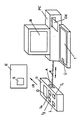
- the figure shows a receiving device E to be programmed with a voting data memory S, a device G for transferring voting data into receiving devices and a personal computer PC with a screen B and a keyboard T.
- the device G contains a display D, buttons T 1. .T n, a charging button L, a socket A and a (not shown) non-volatile tuning data memory.
- a floppy disk DK can be loaded into the personal computer PC, on which a program is stored which is specified by the manufacturer of the device E to be programmed and is used to generate the tuning data.
- the device G is connected via a cable K to the personal computer (PC).
- the tuning data are fed into the device G as follows:
- a start signal is generated and the communication interface for communication with the personal computer PC is generated.
- the device G is thus ready to accept data.
- a program stored on the floppy disk DK is started.
- the program lists on screen B tuning data or data for channels, special channels, transmitter identifications etc. in tabular form. These data are either also stored on the floppy disk DK or are read from the non-volatile tuning data memory of the device G and fed to the personal computer PC or its screen B via the connecting cable K.
- This tuning data can be modified using the keyboard T.
- a takeover key Ü on the keyboard T of the personal computer PC is actuated.
- the voting data are transmitted from the personal computer PC via its (not shown) printer interface and the connecting cable K into the non-volatile tuning data memory of the device G.
- the tuning data can be loaded into the tuning data memory S when a receiving device E is started up.
- the latter data transmission can take place wirelessly, for example by means of infrared transmission, or also via a connecting cable.
Abstract
Description
Die Erfindung betrifft eine Einrichtung zur Überführung von Abstimmdaten in Empfangsgeräte mit den im Oberbegriff des Anspruchs 1 angegebenen Merkmalen.The invention relates to a device for transferring voting data into receiving devices with the features specified in the preamble of claim 1.
Eine derartige Einrichtung ist aus der DE-OS 36 42 365 der Anmelderin bekannt. Die bekannte Einrichtung geht von der Erkenntnis aus, daß aufgrund des zunehmenden Programmangebotes, insbesondere auch über Kabel und Satellit, der Abstimmvorgang von Empfangsgeräten bei deren Inbetriebnahme immer aufwendiger und zeitintensiver wird. Um den Abstimmvorgang zu vereinfachen und zu beschleunigen ist bei der bekannten Einrichtung ein nichtflüchtiger Abstimmdatenspeicher vorgesehen, in welchen die Abstimmdaten mittels einer Tastatur eingegeben werden. Von dieser Einrichtung mit dem nichtflüchtigen Abstimmdatenspeicher aus kann beispielsweise der Fachhändler bei der Aufstellung bzw. Inbetriebnahme des Empfangsgerätes die Abstimmdaten in den Abstimmdatenspeicher des Empfangsgerätes übertragen.Such a device is known from DE-OS 36 42 365 of the applicant. The known device is based on the knowledge that, due to the increasing range of programs, in particular also via cable and satellite, the tuning process of receiving devices becomes more and more complex and time-consuming when they are put into operation. In order to simplify and accelerate the tuning process, a non-volatile tuning data memory is provided in the known device, in which the tuning data is entered using a keyboard. From this device with the non-volatile tuning data memory, for example, the specialist dealer can transfer the tuning data into the tuning data memory of the receiving device when setting up or starting up the receiving device.
Eine ähnliche Einrichtung ist aus der DE-OS 36 40 437 bekannt.A similar device is known from DE-OS 36 40 437.
Weiterhin ist es aus der nicht vorveröffentlichten Patentanmeldung P 37 13 235.0 der Anmelderin bekannt, als nichtflüchtiger Abstimmdatenspeicher eine Magnetbandcassette zu verwenden, auf der die Abstimmdaten in geeigneter Form aufgezeichnet sind.Furthermore, it is known from the applicant's unpublished patent application P 37 13 235.0 to use a magnetic tape cassette as the non-volatile tuning data memory, on which the voting data are recorded in a suitable form.
Die Aufgabe der Erfindung besteht darin, bei einer Einrichtung der im Oberbegriff des Anspruchs 1 angegebenen Art einen Weg aufzuzeigen, wie die Eingabe der Abstimmdaten in den nichtflüchtigen Abstimmdatenspeicher vereinfacht werden kann.The object of the invention is to provide, in a device of the type specified in the preamble of claim 1, a way in which the input of the voting data into the non-volatile voting data memory can be simplified.
Diese Aufgabe wird bei einer Einrichtung der im Oberbegriff des Anspruchs angegebenen Art durch die im kennzeichnenden Teil des Anspruchs 1 angegebenen Merkmale gelöst.This object is achieved in a device of the type specified in the preamble of the claim by the features specified in the characterizing part of claim 1.
Vorteilhafte Ausgestaltungen der beanspruchten Einrichtung ergeben sich aus den Unteransprüchen.Advantageous refinements of the claimed device result from the subclaims.
Die Vorteile der Erfindung ergeben sich aus der Erläuterung eines Ausführungsbeispieles anhand der (einzigen) Figur.The advantages of the invention result from the explanation of an embodiment using the (single) figure.
Die Figur zeigt ein zu programmierendes Empfangsgerät E mit einem Abstimmdatenspeicher S, eine Einrichtung G zur Überführung von Abstimmdaten in Empfangsgeräte und einen Personal-Computer PC mit einem Bildschirm B und einer Tastatur T. Die Einrichtung G enthält ein Display D, Tasten T 1...T n, eine Ladetaste L, eine Anschlußbuchse A und einen (nicht gezeichneten) nichtflüchtigen Abstimmdatenspeicher. In den Personal-Computer PC ist eine Diskette DK ladbar, auf der ein Programm abgespeichert ist, welches vom Hersteller des zu programmierenden Gerätes E vorgegeben ist und zur Generierung der Abstimmdaten verwendet wird. Die Einrichtung G ist über ein Kabel K mit dem Personal-Computer (PC) verbunden.The figure shows a receiving device E to be programmed with a voting data memory S, a device G for transferring voting data into receiving devices and a personal computer PC with a screen B and a keyboard T. The device G contains a display D, buttons T 1. .T n, a charging button L, a socket A and a (not shown) non-volatile tuning data memory. A floppy disk DK can be loaded into the personal computer PC, on which a program is stored which is specified by the manufacturer of the device E to be programmed and is used to generate the tuning data. The device G is connected via a cable K to the personal computer (PC).
Die Einspeisung der Abstimmdaten in die Einrichtung G geschieht wie folgt:The tuning data are fed into the device G as follows:
Nach der Betätigung einer Ladetaste L auf der Einrichtung G wird ein Startsignal erzeugt und damit die Kommunikationsschnittstelle für die Kommunikation mit dem Personal-Computer PC generiert. Damit ist die Einrichtung G zur Übernahme von Daten bereit.After actuation of a charging button L on the device G, a start signal is generated and the communication interface for communication with the personal computer PC is generated. The device G is thus ready to accept data.
Nach dem Einlegen einer Diskette DK in den Personal-Computer PC wird ein auf der Diskette DK abgespeichertes Programm gestartet. Das Programm listet auf dem Bildschirm B Abstimmdaten bzw. Daten für Kanäle, Sonderkanäle, Senderkennungen usw. in Tabellenform auf. Diese Daten sind entweder ebenfalls auf der Diskette DK abgespeichert oder werden aus dem nichtflüchtigen Abstimmdatenspeicher der Einrichtung G ausgelesen und dem Personal-Computer PC bzw. dessen Bildschirm B über das Verbindungskabel K zugeführt. Unter Verwendung der Tastatur T können diese Abstimmdaten modifiziert werden. Sind die gewünschten Abstimmdaten mittels der Tastatur T eingegeben, so wird eine Übernahmetaste Ü auf der Tastatur T des Personal-Computers PC betätigt. In Ansprache auf diese Tastenbetätigung werden die Abstimmdaten vom Personal-Computer PC über dessen (nicht gezeichnete) Druckerschnittstelle und das Verbindungskabel K in den nichtflüchtigen Abstimmdatenspeicher der Einrichtung G übertragen.After inserting a floppy disk DK into the personal computer PC, a program stored on the floppy disk DK is started. The program lists on screen B tuning data or data for channels, special channels, transmitter identifications etc. in tabular form. These data are either also stored on the floppy disk DK or are read from the non-volatile tuning data memory of the device G and fed to the personal computer PC or its screen B via the connecting cable K. This tuning data can be modified using the keyboard T. Once the desired tuning data have been entered using the keyboard T, a takeover key Ü on the keyboard T of the personal computer PC is actuated. In response to this key actuation, the voting data are transmitted from the personal computer PC via its (not shown) printer interface and the connecting cable K into the non-volatile tuning data memory of the device G.
Von dort aus können die Abstimmdaten bei der Inbetriebnahme eines Empfangsgerätes E in dessen Abstimmdatenspeicher S geladen werden. Die letztgenannte Datenübertragung kann leitungslos, beispielsweise mittels einer Infrarot-Übertragung, oder auch über ein Verbindungskabel, erfolgen.From there, the tuning data can be loaded into the tuning data memory S when a receiving device E is started up. The latter data transmission can take place wirelessly, for example by means of infrared transmission, or also via a connecting cable.
Claims (6)
- sie eine Ladetaste (L) aufweist, durch deren Betätigung die Einrichtung (G) zur Übernahme von Abstimmdaten vorbereitet wird,
- ein auf einer Diskette (DK) gespeichertes Programm aufgerufen wird, welches Abstimmdaten auf einem Bildschirm (B) des Personal-Computers (PC) auflistet, und
- die auf dem Bildschirm (B) aufgelisteten Abstimmdaten mittels der Tastatur (T) des Personal-Computers (PC) modifizierbar sind.4. Device according to claim 3, characterized in that
- it has a loading button (L), the actuation of which prepares the device (G) for accepting voting data,
- A program stored on a diskette (DK) is called up, which lists voting data on a screen (B) of the personal computer (PC), and
- The tuning data listed on the screen (B) can be modified using the keyboard (T) of the personal computer (PC).
Applications Claiming Priority (2)
| Application Number | Priority Date | Filing Date | Title |
|---|---|---|---|
| DE3827211 | 1988-08-11 | ||
| DE3827211 | 1988-08-11 |
Publications (2)
| Publication Number | Publication Date |
|---|---|
| EP0354313A2 true EP0354313A2 (en) | 1990-02-14 |
| EP0354313A3 EP0354313A3 (en) | 1990-07-25 |
Family
ID=6360615
Family Applications (1)
| Application Number | Title | Priority Date | Filing Date |
|---|---|---|---|
| EP89110072A Withdrawn EP0354313A3 (en) | 1988-08-11 | 1989-06-03 | Device for the transmission of tuning data in receiver apparatus |
Country Status (1)
| Country | Link |
|---|---|
| EP (1) | EP0354313A3 (en) |
Cited By (12)
| Publication number | Priority date | Publication date | Assignee | Title |
|---|---|---|---|---|
| DE4025302A1 (en) * | 1990-08-09 | 1992-02-13 | Ruf Kg Wilhelm | PROGRAMMING DEVICE FOR PROGRAMMING A REMOTE CONTROL TRANSMITTER |
| DE4300974A1 (en) * | 1993-01-15 | 1993-06-24 | Hans Christian Koehler | Remote controller for range of electronic equipment - has memory programmed with different format instructions that are transmitted over infrared or ultrasonic path |
| EP0553073A1 (en) * | 1990-09-24 | 1993-08-04 | Universal Electronics, Inc. | Universal remote control system |
| EP0596594A1 (en) * | 1992-10-26 | 1994-05-11 | Firstperson, Inc. | Remote control and pointing device |
| EP0601743A1 (en) * | 1992-12-10 | 1994-06-15 | Nokia Mobile Phones Ltd. | Tuning of a radio receiver |
| US5414426A (en) * | 1987-10-14 | 1995-05-09 | Universal Electronics Inc. | Favorite key macro command and chained macro command in a remote control |
| US5414761A (en) * | 1987-10-14 | 1995-05-09 | Universal Electronics Inc. | Remote control system |
| WO1997044897A1 (en) * | 1996-05-17 | 1997-11-27 | Società Italiana per lo Sviluppo dell'Elettronica S.I.SV.EL. S.p.A. | Method for programming television signal receivers and/or television signal receivers implementing the mentioned method |
| EP0938232A2 (en) * | 1992-05-01 | 1999-08-25 | Gemstar Development Corporation | Television program record scheduling using compressed codes |
| WO2001065693A2 (en) * | 2000-03-03 | 2001-09-07 | Koninklijke Philips Electronics N.V. | Method and device for transferring data from one device to another |
| US6430359B1 (en) | 1988-12-23 | 2002-08-06 | Gemstar Development Corporation | Apparatus and method using compressed codes for television program record scheduling |
| US6587067B2 (en) | 1987-10-14 | 2003-07-01 | Universal Electronics Inc. | Universal remote control with macro command capabilities |
Citations (8)
| Publication number | Priority date | Publication date | Assignee | Title |
|---|---|---|---|---|
| JPS60206299A (en) * | 1984-03-29 | 1985-10-17 | Sony Corp | Remote controller |
| EP0176965A2 (en) * | 1984-10-02 | 1986-04-09 | Sony Corporation | Remote control apparatus |
| JPS61177088A (en) * | 1985-01-31 | 1986-08-08 | Nec Home Electronics Ltd | Picture display device |
| DE3640437A1 (en) * | 1986-11-27 | 1988-06-09 | Siemens Ag | Programmable device for adjusting a receiving set of entertainment electronics |
| EP0271058A2 (en) * | 1986-12-11 | 1988-06-15 | GRUNDIG E.M.V. Elektro-Mechanische Versuchsanstalt Max Grundig holländ. Stiftung & Co. KG. | Device for programming receivers |
| DE8717283U1 (en) * | 1987-10-31 | 1988-07-21 | Metz-Werke Gmbh & Co Kg, 8510 Fuerth, De | |
| DE3713235A1 (en) * | 1986-12-11 | 1988-10-27 | Grundig Emv | Device for programming receivers |
| DE3726972A1 (en) * | 1987-08-13 | 1989-02-23 | Graetz Nokia Gmbh | Arrangement for programming receiving units |
-
1989
- 1989-06-03 EP EP89110072A patent/EP0354313A3/en not_active Withdrawn
Patent Citations (8)
| Publication number | Priority date | Publication date | Assignee | Title |
|---|---|---|---|---|
| JPS60206299A (en) * | 1984-03-29 | 1985-10-17 | Sony Corp | Remote controller |
| EP0176965A2 (en) * | 1984-10-02 | 1986-04-09 | Sony Corporation | Remote control apparatus |
| JPS61177088A (en) * | 1985-01-31 | 1986-08-08 | Nec Home Electronics Ltd | Picture display device |
| DE3640437A1 (en) * | 1986-11-27 | 1988-06-09 | Siemens Ag | Programmable device for adjusting a receiving set of entertainment electronics |
| EP0271058A2 (en) * | 1986-12-11 | 1988-06-15 | GRUNDIG E.M.V. Elektro-Mechanische Versuchsanstalt Max Grundig holländ. Stiftung & Co. KG. | Device for programming receivers |
| DE3713235A1 (en) * | 1986-12-11 | 1988-10-27 | Grundig Emv | Device for programming receivers |
| DE3726972A1 (en) * | 1987-08-13 | 1989-02-23 | Graetz Nokia Gmbh | Arrangement for programming receiving units |
| DE8717283U1 (en) * | 1987-10-31 | 1988-07-21 | Metz-Werke Gmbh & Co Kg, 8510 Fuerth, De |
Non-Patent Citations (2)
| Title |
|---|
| PATENT ABSTRACTS OF JAPAN, vol. 010054, (E-385), 4. März 1986; & JP-A-60 206 299 (SONY) * |
| PATENT ABSTRACTS OF JAPAN, vol. 010386, (E-467), 24. Dezember 1986; & JP-A-61 177 088 (NEC HOME ELECTRONICS) * |
Cited By (19)
| Publication number | Priority date | Publication date | Assignee | Title |
|---|---|---|---|---|
| US5414426A (en) * | 1987-10-14 | 1995-05-09 | Universal Electronics Inc. | Favorite key macro command and chained macro command in a remote control |
| US6587067B2 (en) | 1987-10-14 | 2003-07-01 | Universal Electronics Inc. | Universal remote control with macro command capabilities |
| US5414761A (en) * | 1987-10-14 | 1995-05-09 | Universal Electronics Inc. | Remote control system |
| US6430359B1 (en) | 1988-12-23 | 2002-08-06 | Gemstar Development Corporation | Apparatus and method using compressed codes for television program record scheduling |
| DE4025302A1 (en) * | 1990-08-09 | 1992-02-13 | Ruf Kg Wilhelm | PROGRAMMING DEVICE FOR PROGRAMMING A REMOTE CONTROL TRANSMITTER |
| AU648277B2 (en) * | 1990-09-24 | 1994-04-21 | Universal Electronics Inc. | Universal remote control system |
| EP0553073A4 (en) * | 1990-09-24 | 1993-12-15 | Universal Electronics, Inc. | Universal remote control system |
| EP0553073A1 (en) * | 1990-09-24 | 1993-08-04 | Universal Electronics, Inc. | Universal remote control system |
| EP0938232A3 (en) * | 1992-05-01 | 2000-08-23 | Gemstar Development Corporation | Television program record scheduling using compressed codes |
| EP0938232A2 (en) * | 1992-05-01 | 1999-08-25 | Gemstar Development Corporation | Television program record scheduling using compressed codes |
| EP0596594A1 (en) * | 1992-10-26 | 1994-05-11 | Firstperson, Inc. | Remote control and pointing device |
| KR100304796B1 (en) * | 1992-10-26 | 2001-11-22 | 모리스 마이클 에이치. | Control device |
| US5524288A (en) * | 1992-12-10 | 1996-06-04 | Nokia Mobile Phones Ltd. | Tuning of a radio receiver |
| EP0601743A1 (en) * | 1992-12-10 | 1994-06-15 | Nokia Mobile Phones Ltd. | Tuning of a radio receiver |
| DE4300974A1 (en) * | 1993-01-15 | 1993-06-24 | Hans Christian Koehler | Remote controller for range of electronic equipment - has memory programmed with different format instructions that are transmitted over infrared or ultrasonic path |
| WO1997044897A1 (en) * | 1996-05-17 | 1997-11-27 | Società Italiana per lo Sviluppo dell'Elettronica S.I.SV.EL. S.p.A. | Method for programming television signal receivers and/or television signal receivers implementing the mentioned method |
| WO2001065693A2 (en) * | 2000-03-03 | 2001-09-07 | Koninklijke Philips Electronics N.V. | Method and device for transferring data from one device to another |
| WO2001065693A3 (en) * | 2000-03-03 | 2001-12-20 | Koninkl Philips Electronics Nv | Method and device for transferring data from one device to another |
| KR100722175B1 (en) * | 2000-03-03 | 2007-05-29 | 코닌클리케 필립스 일렉트로닉스 엔.브이. | Transferring data from one device to another |
Also Published As
| Publication number | Publication date |
|---|---|
| EP0354313A3 (en) | 1990-07-25 |
Similar Documents
| Publication | Publication Date | Title |
|---|---|---|
| EP0354313A2 (en) | Device for the transmission of tuning data in receiver apparatus | |
| DE3210893C2 (en) | Device arrangement with a television receiver and a Videdo recording and / or reproducing device | |
| DE29724542U1 (en) | Interface device for a memory card | |
| DE3916409A1 (en) | Portable data-transmitting and receiving device | |
| DE2703394A1 (en) | DATA PROCESSING SYSTEM | |
| DE69910900T2 (en) | Data processing for transmission of serial and parallel data | |
| DE2517048C3 (en) | Device for monitoring data transmission in a data processing system | |
| DE2334867A1 (en) | INTERFACE ADAPTATION CIRCUIT FOR CONTROLLING A DATA FLOW | |
| EP0057892A3 (en) | Multi-function control part | |
| DE3727756A1 (en) | METHOD FOR PROCESSING IDENTIFICATION SIGNALS | |
| DE3124991C2 (en) | Digital data magnetic tape recorder | |
| DE4123165C2 (en) | Single-frame playback device | |
| EP0920683B1 (en) | Process for programming electric equipmentand plug-in interfacing card | |
| US4613872A (en) | Recorder for side-by-side digital recording of analog data and digital data | |
| EP0895199B1 (en) | Tachograph with an interface for its connection to a data bus | |
| EP0338290B1 (en) | Method for loading an operating command sequence necessary for operating a microprocessor-controlled electrical device | |
| DE69730679T2 (en) | Plant for the execution of programmed recording | |
| DE19534747C2 (en) | Magnetic card reader interface device | |
| DE19503207C2 (en) | Method for the joint transmission of digital source and control data between data sources and sinks connected via data lines | |
| EP0320708B1 (en) | Video recording device with a memory for preferred programmes | |
| DE3810075C2 (en) | Device for evaluating the operating data of a coin-operated game device | |
| EP1113445B1 (en) | Process and device for coupling signals in a multimedia system | |
| DE3245073A1 (en) | Device for transmitting written information | |
| EP1111911B1 (en) | Device for remote controlling of a television receiver or a videorecorder | |
| EP0301248B1 (en) | Data processing equipment with maintenance processor for control of maintenance operations and procedure for performing such maintenance operations |
Legal Events
| Date | Code | Title | Description |
|---|---|---|---|
| PUAI | Public reference made under article 153(3) epc to a published international application that has entered the european phase |
Free format text: ORIGINAL CODE: 0009012 |
|
| AK | Designated contracting states |
Kind code of ref document: A2 Designated state(s): AT DE FR GB IT |
|
| PUAL | Search report despatched |
Free format text: ORIGINAL CODE: 0009013 |
|
| AK | Designated contracting states |
Kind code of ref document: A3 Designated state(s): AT DE FR GB IT |
|
| STAA | Information on the status of an ep patent application or granted ep patent |
Free format text: STATUS: THE APPLICATION IS DEEMED TO BE WITHDRAWN |
|
| 18D | Application deemed to be withdrawn |
Effective date: 19910126 |