EP0353149A1 - Method for making a display panel, and panel obtained by this method - Google Patents
Method for making a display panel, and panel obtained by this method Download PDFInfo
- Publication number
- EP0353149A1 EP0353149A1 EP89402118A EP89402118A EP0353149A1 EP 0353149 A1 EP0353149 A1 EP 0353149A1 EP 89402118 A EP89402118 A EP 89402118A EP 89402118 A EP89402118 A EP 89402118A EP 0353149 A1 EP0353149 A1 EP 0353149A1
- Authority
- EP
- European Patent Office
- Prior art keywords
- blade
- panel
- blades
- successive
- panel according
- Prior art date
- Legal status (The legal status is an assumption and is not a legal conclusion. Google has not performed a legal analysis and makes no representation as to the accuracy of the status listed.)
- Granted
Links
Images


Classifications
-
- A—HUMAN NECESSITIES
- A47—FURNITURE; DOMESTIC ARTICLES OR APPLIANCES; COFFEE MILLS; SPICE MILLS; SUCTION CLEANERS IN GENERAL
- A47F—SPECIAL FURNITURE, FITTINGS, OR ACCESSORIES FOR SHOPS, STOREHOUSES, BARS, RESTAURANTS OR THE LIKE; PAYING COUNTERS
- A47F5/00—Show stands, hangers, or shelves characterised by their constructional features
- A47F5/08—Show stands, hangers, or shelves characterised by their constructional features secured to the wall, ceiling, or the like; Wall-bracket display devices
- A47F5/0807—Display panels, grids or rods used for suspending merchandise or cards supporting articles; Movable brackets therefor
- A47F5/0846—Display panels or rails with elongated channels; Sliders, brackets, shelves, or the like, slidably attached therein
Definitions
- the present invention relates to a panel which can be used for hanging and presenting objects and, more particularly, such a panel consisting of a succession of horizontal elements determining between them grooves in which members in the form of hooks used, for example, for hanging objects to be displayed or which are integrated into shelves.
- Such panels are known which are made of wood, in particular chipboard, a material chosen because it is easy to work with traditional carpentry tools. These panels are of reduced cost, but they have the disadvantage of having an unpleasant presentation, because they age badly and get dirty, and of being limited in load. These are besides artisanal creations, made to measure.
- the object of the present invention is to remedy the above-mentioned drawbacks of known presentation panels and for this purpose it proposes to provide a presentation panel which, while being simple to manufacture and of a low cost price, ensures excellent load resistance and provides an integrity presentation.
- a resistant and inexpensive material consisting of sheet metal which is worked according to a particularly original operating method is used for the production of presentation panels.
- the sheet is cut into identical strips whose length corresponds to the length of the panel to be obtained, each sheet sheet thus obtained is subjected to successive forming operations to give it a profile such that it has transversely ends arranged substantially in the same plane and which are separated from each other by a projecting intermediate part connected to one of the ends of the blade by an S-profile portion, then the blades are assembled in succession thus formed by applying, over the entire length, the end of a blade against the contiguous end of the previous blade and by spot welding.
- the successive operations of forming the blades comprise: - a first forming operation performing a double fold of the blade around two first transverse fold lines, - a second forming operation performing a double flat folding of the blade, around two new transverse folding lines arranged on either side of said first fold lines, so that the two end parts of the blade are parallel and connected to each other by an S-shaped part, and - A third forming operation performing a double fold of the blade on the side of one of its end parts, around two additional transverse fold lines, so as to bring the two end parts of the blade substantially in the same plane.
- the space between the projecting parts of successive blades can be adjusted as desired, this space possibly being 8 to 10 mm, or more, without modifying the design of manufacturing the blades.
- the blades thus assembled into panels can be hung on blind uprights with a casing system, which allows a particularly pleasant presentation to be obtained by aligning the panels without visible intermediate posts.
- identical sheet metal blades 1 are used, one of which has been shown in FIGS. 1 and 2, having a length which corresponds to that of the panel to be produced.
- the sheet metal blade 1 undergoes, at a first work station, a first forming operation comprising the production of a folded douple around the lines 2 and 3 to present, as shown in FIG. 3, two parallel end portions 4, 5 connected together by a part 6 oriented perpendicular to them.
- a second forming operation is then carried out at a second work station, during which the blade 1 undergoes two folds flat, around the lines 7, 8, so as shown in FIG. 4 that its end portions 4, 5 substantially parallel are connected together by an intermediate part with an S-profile.
- the blade 1 then undergoes a double folding in the vicinity of its end part 5, around the lines 9, 10, so that its extreme parts 4, 5 are substantially in the same plane as seen in FIG. 5.
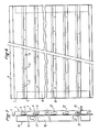
- the blades 1 thus formed are then assembled to each other, as shown in Figures 6 and 7, by applying the end 4 of a blade against the end 5 of the previous blade and joining over the entire length of the blades by welding points 11.
- the space 12 left between the blades 1 during assembly, and which constitutes the grooves in which members 13 can form hooks for hanging the objects to be presented, may for example be in the range of 8 to 10 mm.
- the panel thus obtained is subjected to painting operations in order to present a pleasant appearance allowing its use in all the exhibition places.
- the panels according to the invention are generally manufactured according to standard lengths so that, when the length of the space to be fitted is slightly greater than the length of the panel, a space remains free on the side of the panel after installation of that this which gives an unsightly effect.
- sheet metal blades are produced, each having a profile in the form of a slide for sliding on the end part of a blade of the panel, and which are intended to be fixed individually on a vertical upright secured to the end of the space to fill.
- each of these blades 18 has a U-shaped part overturned terminated at one end by a wing 19 facing outwards and, at the other end, by a wing 20 facing inwards.
- each blade 18 is engaged to slide on a blade 1 of the panel and its end, which projects laterally with respect to the panel, is fixed to the upright 21 secured to the end of the space to be fitted.
- This fixing is carried out by means of a bolt 22 tightening the wing 19 of the blade 18 against the upright 21.
- the bolt 22 serves at the same time to fix the lower end of the blade 18 above, by tightening the wing 20 of this blade between the head of the bolt 22 and a washer 23.
- FIG. 8 shows the result obtained when the successive blades 18 have been fixed.
- the panels according to the invention being generally intended to be associated with a base and a pediment it is understood that these can be provided telescopic so as to be able to extend laterally when the panel itself undergoes lateral extension in the way shown in Figures 8 to 10.
Abstract
Description
La présente invention concerne un panneau utilisable pour l'accrochage et la présentation d'objets et, plus particulièrement, un tel panneau constitué d'une succession d'éléments horizontaux déterminant entre eux des rainures dans lesquelles peuvent s'engager des organes en forme de crochets servant par exemple à la suspension d' objets à présenter ou bien qui sont intégrés à des étagères.The present invention relates to a panel which can be used for hanging and presenting objects and, more particularly, such a panel consisting of a succession of horizontal elements determining between them grooves in which members in the form of hooks used, for example, for hanging objects to be displayed or which are integrated into shelves.
On connaît de tels panneaux qui sont réalisés en bois, en particulier en aggloméré, matériau choisi parce qu'il se travaille facilement avec des outils traditionnels de menuiserie. Ces panneaux sont d'un coût réduit, mais ils présentent l'inconvénient d'avoir une présentation peu agréable, car ils vieillissent mal et se salissent, et d'être limités en charge. Il s'agit d'ailleurs de réalisations artisanales, faites sur mesure.Such panels are known which are made of wood, in particular chipboard, a material chosen because it is easy to work with traditional carpentry tools. These panels are of reduced cost, but they have the disadvantage of having an unpleasant presentation, because they age badly and get dirty, and of being limited in load. These are besides artisanal creations, made to measure.
On connaît aussi des panneaux réalisés en aluminium extrudé ou en bois extrudé avec profilé plastique, qui donnent satisfaction au niveau de la présentation mais moins en ce qui concerne la résistance à la charge, en particulier pour les panneaux en bois. Toutefois, en raison du coût de leurs matériaux constitutifs, ces panneaux sont d'une prix de revient élevé que nuit à leur développement, en particulier pour l'équipement de grandes surfaces d'exposition.There are also known panels made of extruded aluminum or extruded wood with plastic profile, which give satisfaction in terms of presentation but less in terms of load resistance, in particular for wooden panels. However, because of the cost of their constituent materials, these panels are of a high cost price that hinders their development, in particular for the equipment of large exhibition areas.
La présente invention a pour objet de remédier aux inconvénients mentionnés ci-dessus des panneaux de présentation connus et elle propose à cet effet de fournir un panneau de présentation qui, tout en étant de fabrication simple et d'un prix de revient peu élevé, assure une excellente résistance à la charge et procure une présentation irréprochable.The object of the present invention is to remedy the above-mentioned drawbacks of known presentation panels and for this purpose it proposes to provide a presentation panel which, while being simple to manufacture and of a low cost price, ensures excellent load resistance and provides an impeccable presentation.
Selon l'invention on utilise, pour la réalisation de panneaux de présentation, un matériau résistant et peu onéreux constitué par de la tôle qui est travaillée selon un mode opératoire particulièrement original. En effet, selon le procédé de l'invention, on découpe la tôle en lames identiques dont la longueur correspond à la longueur du panneau à obtenir, on soumet chaque lame de tôle ainsi obtenue à des opérations de formage successives pour lui donner un profil tel qu'elle présente transversalement des extrémités disposées sensiblement dans un même plan et qui sont séparées entre elles par une partie intermédiaire en saillie reliée à l'une des extrémités de la lame par une portion à profil en S, puis on assemble en succession les lames ainsi formées en appliquant, sur toute la longueur, l'extrémité d'une lame contre l'extrémité contiguë de la lame précédente et en procédant à une soudure par point.According to the invention, a resistant and inexpensive material consisting of sheet metal which is worked according to a particularly original operating method is used for the production of presentation panels. In fact, according to the method of the invention, the sheet is cut into identical strips whose length corresponds to the length of the panel to be obtained, each sheet sheet thus obtained is subjected to successive forming operations to give it a profile such that it has transversely ends arranged substantially in the same plane and which are separated from each other by a projecting intermediate part connected to one of the ends of the blade by an S-profile portion, then the blades are assembled in succession thus formed by applying, over the entire length, the end of a blade against the contiguous end of the previous blade and by spot welding.
Selon l'invention les opérations successives de formage des lames comprennent :
- une première opération de formage réalisant une double pliure de la lame autour de deux premières lignes de pliage transversales,
- une seconde opération de formage réalisant un double pliage à plat de la lame, autour de deux nouvelles lignes de pliage transversales disposées de part et d'autre desdites premières lignes de pliage, de façon que les deux parties extrêmes de la lame soient parallèles et reliées entre elles par une partie en profil en S, et
- une troisième opération de formage réalisant une double pliure de la lame du côté de l'une de ses parties extrêmes, autour de deux lignes de pliage transversales supplémentaires, de façon à amener les deux parties extrêmes de la lame sensiblement dans un même plan.According to the invention, the successive operations of forming the blades comprise:
- a first forming operation performing a double fold of the blade around two first transverse fold lines,
- a second forming operation performing a double flat folding of the blade, around two new transverse folding lines arranged on either side of said first fold lines, so that the two end parts of the blade are parallel and connected to each other by an S-shaped part, and
- A third forming operation performing a double fold of the blade on the side of one of its end parts, around two additional transverse fold lines, so as to bring the two end parts of the blade substantially in the same plane.
On comprend que, selon le procédé de l'invention, on peut réaliser des panneaux comportant des lames de toutes largeurs et de toutes hauteurs avec le même outillage. On comprend aussi que la conception de formage des lames permet de rattraper, à l'assemblage de celles-ci, les différences de cotes dues à l'accumulation des tolérances des matériaux ainsi que les différences découlant des différentes opérations exécutées.It is understood that, according to the method of the invention, it is possible to produce panels comprising strips of all widths and all heights with the same tool. It is also understood that the blade forming design makes it possible to make up for the differences in dimensions due to the accumulation of material tolerances as well as the differences arising from the various operations carried out when these are assembled.
Lors de l'assemblage des lames entre elles on peut régler à volonté l'espace entre les parties saillantes des lames successives, cet espace pouvant être de 8 à 10 mm, ou plus, sans modifier la conception de fabrication des lames.When assembling the blades together, the space between the projecting parts of successive blades can be adjusted as desired, this space possibly being 8 to 10 mm, or more, without modifying the design of manufacturing the blades.
Les lames ainsi assemblées en panneaux peuvent être accrochées sur des montants en aveugle avec un système d'emboîtage, ce qui permet l'obtention d'une présentation particulièrement agréable par alignement des panneaux sans poteaux intermédiaires visibles.The blades thus assembled into panels can be hung on blind uprights with a casing system, which allows a particularly pleasant presentation to be obtained by aligning the panels without visible intermediate posts.
Pour bien faire comprendre le procédé de fabrication selon l'invention on en décrira ci-après, à titre d'exemple sans caractère limitatif, une forme de réalisation préférée en référence au dessin schématique annexé dans lequel :
- la figure 1 est une vue de face d'une lame de tôle utilisée pour la mise en oeuvre du procédé selon l'invention ;
- la figure 2 est une coupe transversale de la lame de la figure 1 ;
- les figures 3 à 5 sont des coupes transversales de la lame des figures 1 et 2 respectivement après les première, deuxième et troisième opérations de formage ;
- la figure 6 est une vue de face d'un panneau obtenu selon le procédé de l'invention, par assemblage de lames de la figure 5 ;
- la figure 7 est une vue de profil du panneau de la figure 6 ;
- la figure 8 est une vue de face correspondant à la figure 6, dans une application particulière permettant une extension réglable du panneau ;
- la figure 9 est une vue de profil partielle correspondant à la figure 8 ; et
- la figure 10 est, à plus grande échelle, une vue en coupe verticale partielle d'une lame coulissante servant à l'extension du panneau.
- Figure 1 is a front view of a sheet metal blade used for the implementation of the method according to the invention;
- Figure 2 is a cross section of the blade of Figure 1;
- Figures 3 to 5 are cross sections of the blade of Figures 1 and 2 respectively after the first, second and third forming operations;
- Figure 6 is a front view of a panel obtained according to the method of the invention, by assembling the blades of Figure 5;
- Figure 7 is a side view of the panel of Figure 6;
- Figure 8 is a front view corresponding to Figure 6, in a particular application allowing an adjustable extension of the panel;
- Figure 9 is a partial profile view corresponding to Figure 8; and
- Figure 10 is, on a larger scale, a partial vertical sectional view of a sliding blade for the extension of the panel.
Pour la fabrication de panneaux de présentation selon l'invention, on utilise des lames de tôle identiques 1, dont une a été représentée aux figures 1 et 2, ayant une longueur qui correspond à celle du panneau à réaliser. La lame de tôle 1 subit, à un premier poste de travail, une première opération de formage comprenant la réalisation d'un douple pli autour des lignes 2 et 3 pour présenter, comme représenté à la figure 3, deux parties extrêmes parallèles 4, 5 reliées ensemble par une partie 6 orientée perpendiculairement à elles.For the production of presentation panels according to the invention, identical
Une seconde opération de formage est alors réalisée à un second poste de travail, au cours de laquelle la lame 1 subit deux pliages à plat, autour des lignes 7, 8, de façon comme représenté à la figure 4 que ses parties extrêmes 4, 5 sensiblement parallèles soient reliées ensemble par une partie intermédiaire à profil en S.A second forming operation is then carried out at a second work station, during which the
Sur un troisième poste de formage, la lame 1 subit ensuite un double pliage au voisinage de sa partie extrême 5, autour des lignes 9, 10, de façon que ses parties extrêmes 4, 5 soient sensiblement dans un même plan comme on le voit à la figure 5.On a third forming station, the
Les lames 1 ainsi formées sont alors assemblées les unes aux autres, comme représenté aux figures 6 et 7, par application de l'extrémité 4 d'une lame contre l'extrémité 5 de la lame précédente et solidarisation sur toute la longueur des lames par des points de soudure 11. L'espace 12 laissé entre les lames 1 lors de l'assemblage, et qui constitue les rainures dans lesquelles pourront s'engager des organes 13 formant crochets pour la suspension des objets à présenter, peut être par exemple de l'ordre de 8 à 10 mm.The
Aux panneaux ainsi constitués d'un nombre déterminé de lames 1, par exemple neuf ou treize lames, sont fixés des montants verticaux 14 en forme de cornière. Comme on le voit aux figures 6 et 7, la face arrière du panneau est soudée à une aile 15 du montant 14, alors que l'autre aile 16 du montant présente des découpes 17 conçues pour s'accrocher sur des supports muraux.To the panels thus formed of a determined number of
Après fabrication, le panneau ainsi obtenu est soumis à des opérations de peinture afin de présenter un aspect agréable permettant son utilisation dans tous les lieux d'exposition.After manufacture, the panel thus obtained is subjected to painting operations in order to present a pleasant appearance allowing its use in all the exhibition places.
Les panneaux selon l'invention sont généralement fabriqués selon des longueurs standards de sorte que, lorsque la longueur de l'espace à équiper est légèrement supérieure à la longueur du panneau, un espace reste libre sur le côté du panneau après mise en place de celui-ci ce qui procure un effet disgracieux. Pour remédier à cet inconvénient on réalise des lames en tôle présentant chacune un profil en forme de glissière pour coulisser sur la partie extrême d'une lame du panneau, et qui sont destinées à être fixées individuellement sur un montant vertical solidaire de l'extrémité de l'espace à combler.The panels according to the invention are generally manufactured according to standard lengths so that, when the length of the space to be fitted is slightly greater than the length of the panel, a space remains free on the side of the panel after installation of that this which gives an unsightly effect. To overcome this drawback, sheet metal blades are produced, each having a profile in the form of a slide for sliding on the end part of a blade of the panel, and which are intended to be fixed individually on a vertical upright secured to the end of the space to fill.
Comme on le voit aux figures 8 à 10, chacune de ces lames 18 présente une partie en forme de U renversée terminée à une extrémité par une aile 19 tournée vers l'extérieur et, à l'autre extrémité, par une aile 20 tournée vers l'intérieur. Pour la mise en place, chaque lame 18 est engagée pour coulisser sur une lame 1 du panneau et son extrémité, qui fait saillie latéralement par rapport au panneau, est fixée au montant 21 solidaire de l'extrémité de l'espace à équiper. Cette fixation s'effectue au moyen d'un boulon 22 serrant l'aile 19 de la lame 18 contre le montant 21. Comme on le voit à la figure 10 le boulon 22 sert en même temps à fixer l'extrémité inférieure de la lame 18 précédente, par serrage de l'aile 20 de cette lame entre la tête du boulon 22 et une rondelle 23. La figure 8 montre le résultat obtenu lorsque les lames 18 successives ont été fixées.As seen in Figures 8 to 10, each of these
Les panneaux selon l'invention étant destinés généralement à être associés à un socle et à un fronton on comprend que ceux-ci peuvent être prévus télescopiques de façon à pouvoir s'étendre latéralement lorsque le panneau subit lui-même une extension latérale de la façon représentée aux figures 8 à 10.The panels according to the invention being generally intended to be associated with a base and a pediment it is understood that these can be provided telescopic so as to be able to extend laterally when the panel itself undergoes lateral extension in the way shown in Figures 8 to 10.
On comprendra que la description ci-dessus a été donnée à simple titre d'exemple, sans caractère limitatif, et que des adjonctions ou des modifications constructives pourraient y être apportées sans sortir du cadre de l'invention définie par les revendication qui suivent.It will be understood that the above description has been given by way of example, without limitation, and that additions or constructive modifications could be made without departing from the scope of the invention defined by the claims which follow.
Claims (10)
- à découper des lames (1) de tôle identiques dont la longueur correspond à celle du panneau à réaliser,
- à soumettre chaque lame (1) ainsi obtenue à des opérations de formage successives pour lui donner un profil tel qu'elle présente, en direction transversale, des extrémités (4, 5) disposées sensiblement dans un même plan et séparées entre elles par une partie intermédiaire en saillie qui est reliée à l'une desdites extrémités pa une portion en S, et
- à disposer ces lames à la suite les unes des autres de façon que les parties saillantes de deux lames successives déterminent une rainure,
caractérisé en ce que les lames (1) ainsi formées sont assemblées ensemble en appliquant, sur toute la longueur, une extrémité (5) d'une lame sur l'extrémité opposée (4) de la lame précédente de façon que ces extrémités se superposent, et en procédant à une soudure par point.1. A method of manufacturing a support panel for the presentation of objects, characterized in that it comprises the successive operations consisting
- cutting blades (1) of identical sheet metal the length of which corresponds to that of the panel to be produced,
- subjecting each blade (1) thus obtained to successive forming operations to give it a profile such that it has, in transverse direction, ends (4, 5) arranged substantially in the same plane and separated from each other by a intermediate protruding part which is connected to one of said ends by an S-shaped portion, and
- placing these blades one after the other so that the projecting parts of two successive blades define a groove,
characterized in that the blades (1) thus formed are assembled together by applying, over the entire length, one end (5) of a blade to the opposite end (4) of the preceding blade so that these ends overlap , and by spot welding.
- une première opération de formage réalisant une double pliure de la lame (1) autour de deux premières lignes de pliage transversale (2, 3),
- une seconde opération de formage réalisant un double pliage à plat de la lame (1) autour de deux nouvelles lignes de pliage transversales (7, 8) disposées de part et d'autre des deux premières lignes de pliage (2, 3), de façon que les extrémités (4, 5) de la lame (1) soient parallèles et reliées entre elles par une partie à profil en S,
- une troisième opération de formage réalisant une double pliure de la lame (1) du côté de l'une de ses extrémités (5), autour de deux lignes de pliage transversales supplémentaires (9, 10), de façon à amener les deux extrémités (4, 5) de la lame (1) sensiblement dans un même plan.2. Method according to claim 1, characterized in that the successive forming operations of the blades (1) comprise:
a first forming operation performing a double fold of the blade (1) around two first transverse fold lines (2, 3),
a second forming operation performing a double flat folding of the blade (1) around two new transverse folding lines (7, 8) arranged on either side of the first two folding lines (2, 3), so that the ends (4, 5) of the blade (1) are parallel and connected to each other by a section with an S-profile,
- a third forming operation performing a double fold of the blade (1) on the side of one of its ends (5), around two additional transverse fold lines (9, 10), so as to bring the two ends (4, 5) of the blade (1) substantially in the same plane.
Applications Claiming Priority (2)
| Application Number | Priority Date | Filing Date | Title |
|---|---|---|---|
| FR8810247 | 1988-07-29 | ||
| FR8810247A FR2634637B1 (en) | 1988-07-29 | 1988-07-29 | METHOD FOR MANUFACTURING A DISPLAY SUPPORT PANEL, AND PANEL OBTAINED BY IMPLEMENTING THE METHOD |
Publications (2)
| Publication Number | Publication Date |
|---|---|
| EP0353149A1 true EP0353149A1 (en) | 1990-01-31 |
| EP0353149B1 EP0353149B1 (en) | 1994-06-01 |
Family
ID=9368915
Family Applications (1)
| Application Number | Title | Priority Date | Filing Date |
|---|---|---|---|
| EP89402118A Revoked EP0353149B1 (en) | 1988-07-29 | 1989-07-26 | Method for making a display panel, and panel obtained by this method |
Country Status (7)
| Country | Link |
|---|---|
| US (1) | US5014902A (en) |
| EP (1) | EP0353149B1 (en) |
| AT (1) | ATE106209T1 (en) |
| DE (2) | DE68915634T2 (en) |
| ES (1) | ES2014393T3 (en) |
| FR (1) | FR2634637B1 (en) |
| GR (1) | GR900300156T1 (en) |
Cited By (1)
| Publication number | Priority date | Publication date | Assignee | Title |
|---|---|---|---|---|
| FR2651981A1 (en) * | 1989-09-21 | 1991-03-22 | Stal Ind | System and strip for making a display means |
Families Citing this family (6)
| Publication number | Priority date | Publication date | Assignee | Title |
|---|---|---|---|---|
| GB0302233D0 (en) * | 2003-01-31 | 2003-03-05 | Bros Bros Elland Ltd | Wall display system panel |
| US11583074B2 (en) | 2017-10-27 | 2023-02-21 | Elfa International Ab | Wall-mounted, configurable storage system |
| US11375812B2 (en) | 2018-09-12 | 2022-07-05 | Elfa International Ab | Wall-mounted, configurable storage system |
| SE543835C2 (en) | 2019-12-23 | 2021-08-10 | Elfa Int Ab | Shelf storage system comprising hang standards with screw holes at distances corresponding to desired bracket to bracket distances |
| EP4142543A1 (en) | 2020-04-30 | 2023-03-08 | Elfa International AB | Suspension system comprising a rear rail arranged with flanges at least partially extending in different directions and a hangstandard arrangable thereto |
| SE544174C2 (en) | 2020-04-30 | 2022-02-22 | Elfa Int Ab | Hang standard and storage system including the hang standard |
Citations (5)
| Publication number | Priority date | Publication date | Assignee | Title |
|---|---|---|---|---|
| FR1551912A (en) * | 1966-08-19 | 1969-01-03 | ||
| DE2250987A1 (en) * | 1972-10-18 | 1974-05-02 | Althaus K Metall | GROOVE WALL FOR SALES ROOMS |
| US4187407A (en) * | 1978-09-05 | 1980-02-05 | General Motors Corporation | Welded lap joint and method of making the same |
| US4450970A (en) * | 1981-09-11 | 1984-05-29 | J. A. Wilson Display Ltd. | Display panels |
| US4607753A (en) * | 1983-06-28 | 1986-08-26 | Ready Metal Manufacturing Company | Slotted wall merchandise display panel |
Family Cites Families (3)
| Publication number | Priority date | Publication date | Assignee | Title |
|---|---|---|---|---|
| BE794911A (en) * | 1972-02-05 | 1973-05-29 | Kaspar Klaus | TRAVELABLE AREA FOR MECHANICAL INSTALLATIONS OF GARAGES, RAMPS, LIFTING PLATFORMS OR SIMILAR |
| JPS60148173U (en) * | 1984-03-15 | 1985-10-01 | マツダ株式会社 | car roof |
| JPS60244427A (en) * | 1984-05-17 | 1985-12-04 | Nakagawa Kinzoku Kogyosho:Kk | Forming method of metallic spandrel for architecture for building |
-
1988
- 1988-07-29 FR FR8810247A patent/FR2634637B1/en not_active Expired - Lifetime
-
1989
- 1989-07-26 ES ES89402118T patent/ES2014393T3/en not_active Expired - Lifetime
- 1989-07-26 AT AT89402118T patent/ATE106209T1/en not_active IP Right Cessation
- 1989-07-26 DE DE68915634T patent/DE68915634T2/en not_active Revoked
- 1989-07-26 DE DE198989402118T patent/DE353149T1/en active Pending
- 1989-07-26 EP EP89402118A patent/EP0353149B1/en not_active Revoked
- 1989-07-28 US US07/386,091 patent/US5014902A/en not_active Expired - Fee Related
-
1991
- 1991-09-27 GR GR90300156T patent/GR900300156T1/en unknown
Patent Citations (5)
| Publication number | Priority date | Publication date | Assignee | Title |
|---|---|---|---|---|
| FR1551912A (en) * | 1966-08-19 | 1969-01-03 | ||
| DE2250987A1 (en) * | 1972-10-18 | 1974-05-02 | Althaus K Metall | GROOVE WALL FOR SALES ROOMS |
| US4187407A (en) * | 1978-09-05 | 1980-02-05 | General Motors Corporation | Welded lap joint and method of making the same |
| US4450970A (en) * | 1981-09-11 | 1984-05-29 | J. A. Wilson Display Ltd. | Display panels |
| US4607753A (en) * | 1983-06-28 | 1986-08-26 | Ready Metal Manufacturing Company | Slotted wall merchandise display panel |
Non-Patent Citations (1)
| Title |
|---|
| PATENT ABSTRACTS OF JAPAN, vol. 10, no. 114 (M-473)[2171], 26th avril 1986; & JP-A-60 244 427 (NAKAGAWA KINZOKU KOGYOSHO K.K.) 04-12-1985 * |
Cited By (1)
| Publication number | Priority date | Publication date | Assignee | Title |
|---|---|---|---|---|
| FR2651981A1 (en) * | 1989-09-21 | 1991-03-22 | Stal Ind | System and strip for making a display means |
Also Published As
| Publication number | Publication date |
|---|---|
| DE68915634T2 (en) | 1994-11-10 |
| EP0353149B1 (en) | 1994-06-01 |
| FR2634637A1 (en) | 1990-02-02 |
| DE68915634D1 (en) | 1994-07-07 |
| ES2014393T3 (en) | 1994-09-01 |
| ATE106209T1 (en) | 1994-06-15 |
| ES2014393A4 (en) | 1990-07-16 |
| US5014902A (en) | 1991-05-14 |
| FR2634637B1 (en) | 1991-12-13 |
| GR900300156T1 (en) | 1991-09-27 |
| DE353149T1 (en) | 1990-09-06 |
Similar Documents
| Publication | Publication Date | Title |
|---|---|---|
| EP0353149B1 (en) | Method for making a display panel, and panel obtained by this method | |
| FR2571949A1 (en) | Folding display case having an automatic unfolding capability | |
| BE1011814A4 (en) | Separation element form panel for making walls and displays for temporary events. | |
| CA1029520A (en) | Composite structures | |
| FR2803365A1 (en) | METAL PROFILE, PARTICULARLY FOR URBAN FURNITURE | |
| EP3041387B1 (en) | Bottle support | |
| FR2879138A1 (en) | Track for motor vehicle seat, has movable track unit including sheet metal support with core presenting bracket housed in recess, where flap is directly welded on lower portion of core and projection zone is welded on contour of recess | |
| EP0637007A1 (en) | Panel type structure, particulary for scenery | |
| EP0212996B1 (en) | Set of elements for the arrangement of exhibition halls, shops and other venues | |
| FR2714803A1 (en) | Shelf with stiffening pillars. | |
| FR2650015A1 (en) | SUPPORT PLATE FOR EXTERIOR WALL COVERING | |
| FR2682209A1 (en) | Label holder which can be fitted to display furniture in a retail shop | |
| FR2539336A1 (en) | Painting booth made from modular panels | |
| FR2740805A1 (en) | Angle bracket connecting wooden beam to concrete structure | |
| FR2679284A1 (en) | SHELTER IN PARTICULAR INTENDED TO BE INSTALLED IN A STADIUM NEAR THE PLAYGROUND. | |
| FR2797206A1 (en) | METHOD FOR RIGID CONNECTION BETWEEN A TUBULAR ELEMENT AND A METALLIC PLANE ELEMENT APPLICABLE IN PARTICULAR TO LADDERS AND THE LIKE | |
| FR2725354A1 (en) | Display stand with shelves held on vertical posts | |
| FR2812526A1 (en) | System for building cardboard stand for displaying articles for sale comprises shelves made up of polygonal base and peripheral wall and with slots in their corners through which polygonal tubes which lock together to form a rack | |
| FR2820962A1 (en) | Hanging system for display rails for articles in blister packs comprises claw at end of rail with U-shaped section at top, which fits over mounting rail and has inward-facing steps on its front surface | |
| FR3090980A1 (en) | System comprising a shelf and a label holder device, configured to equip a device for presenting articles of goods | |
| FR2500284A3 (en) | Upright for shelving or furniture - consists of two tubular profiled sections joined by nut and screw | |
| FR2534462A1 (en) | Modular furniture | |
| EP1722065A1 (en) | Panel of hollow reinforcement beams | |
| FR2758310A3 (en) | Flat bottom foldable bag | |
| FR2913704A1 (en) | Office's walls connecting method, involves realizing connection between walls by bringing one profile in contact with another profile, where end of sides of latter profile and base of latter profile are engaged with part of former profile |
Legal Events
| Date | Code | Title | Description |
|---|---|---|---|
| PUAI | Public reference made under article 153(3) epc to a published international application that has entered the european phase |
Free format text: ORIGINAL CODE: 0009012 |
|
| AK | Designated contracting states |
Kind code of ref document: A1 Designated state(s): AT BE CH DE ES GB GR IT LI LU NL SE |
|
| ITCL | It: translation for ep claims filed |
Representative=s name: FIAMMENGHI FIAMMENGHI RACHELI |
|
| TCNL | Nl: translation of patent claims filed | ||
| GBC | Gb: translation of claims filed (gb section 78(7)/1977) | ||
| TCAT | At: translation of patent claims filed | ||
| DET | De: translation of patent claims | ||
| 17P | Request for examination filed |
Effective date: 19900731 |
|
| 17Q | First examination report despatched |
Effective date: 19920416 |
|
| GRAA | (expected) grant |
Free format text: ORIGINAL CODE: 0009210 |
|
| AK | Designated contracting states |
Kind code of ref document: B1 Designated state(s): AT BE CH DE ES GB GR IT LI LU NL SE |
|
| PG25 | Lapsed in a contracting state [announced via postgrant information from national office to epo] |
Ref country code: NL Effective date: 19940601 Ref country code: GR Free format text: LAPSE BECAUSE OF NON-PAYMENT OF DUE FEES Effective date: 19940601 Ref country code: AT Effective date: 19940601 |
|
| REF | Corresponds to: |
Ref document number: 106209 Country of ref document: AT Date of ref document: 19940615 Kind code of ref document: T |
|
| REF | Corresponds to: |
Ref document number: 68915634 Country of ref document: DE Date of ref document: 19940707 |
|
| ITF | It: translation for a ep patent filed |
Owner name: FIAMMENGHI FIAMMENGHI RACHELI |
|
| PGFP | Annual fee paid to national office [announced via postgrant information from national office to epo] |
Ref country code: GB Payment date: 19940726 Year of fee payment: 6 |
|
| PGFP | Annual fee paid to national office [announced via postgrant information from national office to epo] |
Ref country code: ES Payment date: 19940730 Year of fee payment: 6 |
|
| ITTA | It: last paid annual fee | ||
| PG25 | Lapsed in a contracting state [announced via postgrant information from national office to epo] |
Ref country code: LU Free format text: LAPSE BECAUSE OF NON-PAYMENT OF DUE FEES Effective date: 19940731 |
|
| PGFP | Annual fee paid to national office [announced via postgrant information from national office to epo] |
Ref country code: CH Payment date: 19940809 Year of fee payment: 6 |
|
| PGFP | Annual fee paid to national office [announced via postgrant information from national office to epo] |
Ref country code: DE Payment date: 19940810 Year of fee payment: 6 |
|
| PGFP | Annual fee paid to national office [announced via postgrant information from national office to epo] |
Ref country code: BE Payment date: 19940831 Year of fee payment: 6 |
|
| PG25 | Lapsed in a contracting state [announced via postgrant information from national office to epo] |
Ref country code: SE Effective date: 19940901 |
|
| REG | Reference to a national code |
Ref country code: ES Ref legal event code: FG2A Ref document number: 2014393 Country of ref document: ES Kind code of ref document: T3 |
|
| GBT | Gb: translation of ep patent filed (gb section 77(6)(a)/1977) |
Effective date: 19940819 |
|
| NLV1 | Nl: lapsed or annulled due to failure to fulfill the requirements of art. 29p and 29m of the patents act | ||
| PLBI | Opposition filed |
Free format text: ORIGINAL CODE: 0009260 |
|
| 26 | Opposition filed |
Opponent name: LA CHEMISE LACOSTE Effective date: 19950227 |
|
| PG25 | Lapsed in a contracting state [announced via postgrant information from national office to epo] |
Ref country code: GB Effective date: 19950726 |
|
| PG25 | Lapsed in a contracting state [announced via postgrant information from national office to epo] |
Ref country code: ES Free format text: LAPSE BECAUSE OF NON-PAYMENT OF DUE FEES Effective date: 19950727 |
|
| PG25 | Lapsed in a contracting state [announced via postgrant information from national office to epo] |
Ref country code: BE Effective date: 19950731 |
|
| BERE | Be: lapsed |
Owner name: FAPEC Effective date: 19950731 |
|
| RDAG | Patent revoked |
Free format text: ORIGINAL CODE: 0009271 |
|
| REG | Reference to a national code |
Ref country code: CH Ref legal event code: PL |
|
| STAA | Information on the status of an ep patent application or granted ep patent |
Free format text: STATUS: PATENT REVOKED |
|
| GBPC | Gb: european patent ceased through non-payment of renewal fee |
Effective date: 19950726 |
|
| 27W | Patent revoked |
Effective date: 19951215 |