EP0353025A2 - Sliding test device for assays - Google Patents
Sliding test device for assays Download PDFInfo
- Publication number
- EP0353025A2 EP0353025A2 EP89307548A EP89307548A EP0353025A2 EP 0353025 A2 EP0353025 A2 EP 0353025A2 EP 89307548 A EP89307548 A EP 89307548A EP 89307548 A EP89307548 A EP 89307548A EP 0353025 A2 EP0353025 A2 EP 0353025A2
- Authority
- EP
- European Patent Office
- Prior art keywords
- filter
- pad
- absorbent material
- absorbent
- liquid
- Prior art date
- Legal status (The legal status is an assumption and is not a legal conclusion. Google has not performed a legal analysis and makes no representation as to the accuracy of the status listed.)
- Granted
Links
Images

Classifications
-
- B—PERFORMING OPERATIONS; TRANSPORTING
- B01—PHYSICAL OR CHEMICAL PROCESSES OR APPARATUS IN GENERAL
- B01L—CHEMICAL OR PHYSICAL LABORATORY APPARATUS FOR GENERAL USE
- B01L3/00—Containers or dishes for laboratory use, e.g. laboratory glassware; Droppers
- B01L3/50—Containers for the purpose of retaining a material to be analysed, e.g. test tubes
- B01L3/502—Containers for the purpose of retaining a material to be analysed, e.g. test tubes with fluid transport, e.g. in multi-compartment structures
-
- B—PERFORMING OPERATIONS; TRANSPORTING
- B01—PHYSICAL OR CHEMICAL PROCESSES OR APPARATUS IN GENERAL
- B01D—SEPARATION
- B01D61/00—Processes of separation using semi-permeable membranes, e.g. dialysis, osmosis or ultrafiltration; Apparatus, accessories or auxiliary operations specially adapted therefor
- B01D61/14—Ultrafiltration; Microfiltration
- B01D61/18—Apparatus therefor
-
- G—PHYSICS
- G01—MEASURING; TESTING
- G01N—INVESTIGATING OR ANALYSING MATERIALS BY DETERMINING THEIR CHEMICAL OR PHYSICAL PROPERTIES
- G01N33/00—Investigating or analysing materials by specific methods not covered by groups G01N1/00 - G01N31/00
- G01N33/48—Biological material, e.g. blood, urine; Haemocytometers
- G01N33/50—Chemical analysis of biological material, e.g. blood, urine; Testing involving biospecific ligand binding methods; Immunological testing
- G01N33/53—Immunoassay; Biospecific binding assay; Materials therefor
- G01N33/5302—Apparatus specially adapted for immunological test procedures
Definitions
- This invention relates to a construction of a test device that allows it to alternate between no-liquid flow, and liquid flow, through a filter, the filter being used to separate a reaction product from the reagents that provide the reaction product.
- Diagnostic devices have been provided in the past for conducting immunoreactions in one or more test wells to determine the qualitative existence of pregnancy or an infectious disease.
- Such devices commonly include a filter membrane at the bottom of the well to separate out free, unreacted immunoreagents, from complexed immunoreagents. (The former pass through the membrane.)
- Underneath such membranes is preferably located an absorbent material to absorb the liquid of the reaction mixture. It has been conventional in such devices to provide for control of liquid flow, so as to first retain the liquid in the well above the membrane for an incubation period, and then to allow flow through the membrane.
- Previously provided mechanisms for controlling the flow include an aperture in the housing for the absorbent material underneath, and seals for opening and closing the aperture.
- U.S. Patent 4,734,262 by Bagshawe A recent development towards this end is that described in U.S. Patent 4,734,262 by Bagshawe.
- a non-absorbent seal is provided at the bottom of the well, between the opening in the well and the filter membrane that is combined with an absorbent material.
- the device is constructed to provide relative movement in the form of reciprocation, between the seal and the opening, but not between the seal and the filter membrane. That is, both the seal and membrane are caused to deflect away from the opening, such as by applying pressure to the top chamber, allowing liquid to pour out onto the filter membrane.
- Such a construction has several disadvantages.
- seal covers the surface of the filter membrane at the top, thus decreasing the area available for filtration, and most importantly, it prevents the filter from being observed through the opening for a detectable change indicative of a positive reaction.
- a second disadvantage is a requirement that there be a positive driving pressure to open the seal. This requires an auxiliary instrument, such as a vacuum source, besides what can be done using just the operator's own manipulation.
- a test device useful for conducting a reaction comprising a) a well configured to confine temporarily a liquid patient sample admixed with at least one reagent, to provide the reaction, b) a filter at the bottom of the well with pores effective to pass free, unreacted reagent but not complexed or reacted reagent, and c) an absorbent material underneath the filter effective to draw off liquid in the well after the reaction.
- the device is characterized in that it further includes d) a non-absorbent pad underneath the filter, adjacent to the absorbent material, and e) means for moving the filter and the absorbent material relative to each other, and the filter and the pad relative to each other, between two positions, one in which the filter contacts the non-absorbent pad and the other in which the filter contacts the absorbent material.
- a liquid testing device is provided with a liquid-confining well, a filter, and an absorbent material underneath, that allows flow or no flow of liquid through the filter without the use of vent seals of carefully controlled tolerances.
- the invention is described herein in the context of the preferred embodiments, in which the device has three pairs of upper/lower compartments, to immunoassay a) the patient sample, b) a positive control and c) a negative control, all more or less simultaneously.
- the filters are shown as sliding between two positions.
- aspects of the invention are useful with only a single pair of compartments, and with any kind of reaction and any form of relative movement between the filter and its absorbent material.
- the chemistries provide for an immunoassay, in which there is separately received at three filters in three compartments, a patient antigen complexed with an antigen, a positive control for the complex so formed, and a negative control for the complex so formed, respectively, as is conventional.
- Figures 1A and 1B illustrate a related device 10 provided by the prior art, specifically one taught by U.S. Patent No. 4,734,262 noted above.
- An upper compartment or well 12 has at the bottom of it, an aperture 14 that has mounted below it, a non-absorbent seal 16, that sits on the filter-absorbent material 18 held in place by member 20. Liquid placed in well 12 will not pour into or through material 18 because seal 16 blocks it, Figure 1A.
- Figure 18 such as by a positive pressure applied to well 12 (arrow 22) or a vacuum applied to material 18, both the seal and material 18 pull away from aperture 14 and liquid flow into the filter-absorbent material occurs, arrows 24.
- the disadvantages of such a device are that the presence of seal 16 prevents reading any color change through the top, and it requires the application of a pressure differential to unseat seal 16.
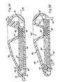
- an improved device 50 comprises, Figure 2, three upper compartments or wells 52a, 52b, and 52c.
- the bottom 53 of each well, Figure 3A, is covered with a porous filter 58 which will pass liquid through it unless such flow is blocked either by a liquid lock or some other means.
- Both the well and its filter are carried on an upper housing 59 having a sloped forward edge 61 and a rear groove 63.
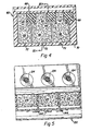
- Below housing 59 is a lower housing member 60, Figures 2-4, having in an adjacent, and preferably contiguous relationship, both an absorbent material 66 and a non-absorbent seal or pad 68, Figure 4.
- the footprint 58 of the filter of each well 52a, 52b and 52c, is shown as contacting pad 68, Figure 4, before each well moves to where the filter contacts the adjacent absorbent material 66.
- the height "h", Figure 3A, of both material 66 and the pad 68 is such as to compress material 66 or pad 68 slightly, when filter 58 contacts either one.
- lower housing 60 The material 66 and pads 68 are held within lower housing 60, as shown in Figure 4.
- Such lower housing has a forward edge 70 that optionally bears one or more vent apertures 72, and a track groove 74, Figure 3A, that accommodates edge 61 of upper housing 59 in a sliding relationship.
- Rearward portion 76 of housing 60 has a lip 78 that slidably extends into groove 63.
- Vertical ribs (not shown) can be located in housing 60 between, e.g., each material 66, to keep them in place.
- upper housing 59 moves relative to lower housing 60 preferably by sliding with respect thereto.
- This provides a sliding relationship between filter 58 of each well, and both its non-absorbent pad 68 and its absorbent material 66.
- the footprint 58 of the filter slides as per arrow 80, from contact with non-absorbent pad 68, to absorbent material 66. That is, each well goes from a non-liquid-flow condition to a liquid-flowing condition, respectively, since apertures 72 insure there is no liquid lock.
- the word "closed” can be printed at 85 on the top of housing 60, Figure 2, to inform the user that, when configured as shown in Figure 2, the wells are closed off from flow. A printing of the word "open” (not shown) is useful at the other end 87 of the top of housing 60.
- device 50′ comprises an upper housing 59′ and a lower housing 60′.
- Housing 59′ includes wells such as well 52b′, and filter 58′, and housing 60′ houses absorbent material 66′ and non-absorbent pad 68′, all constructed as described above.
- upper housing 59′ remains stationary by reason of its four supports 89 that are attached, for example, at the four corners of such housing.
- Housing 59′ also includes a lip 61′ that fits in a groove 74′ provided in housing 60′, and a rear groove 63′ that accommodates lip 78′ of housing 60′. Housing 60′ is slung to slide within groove 63′ and on lip 61′ as a track support, in and out of the plane of Fig. 3B.
- Filters 58 can be polyamides, such as nylon, and for example nylon-66 microporous membranes manufactured under the tradenames BIODYNE A or ULTRIPOR N-66 by Pall Corporation. Most preferably, the membranes are precoated (prior to use) with one or more water-soluble proteins, such as casein derivatives obtained from acylation, alkylation or sulfonylation of the casein. Various optional additional treatments can be given to the filter upper surface during or before assembly.
- Absorbent material 66 can be any bibulous material, having a sufficient pore volume to soak up about 2 cc of liquid.
- Useful materials include cellulose acetate, cotton, and rayon.
- pads 68 are selected from non-absorbent materials, such as resilient neoprene laminated with a hydrophobic plastic, for example, polypropylene.
- the resiliency is selected to allow filter 58 to compress pad 68 with sufficient pressure as to withstand about 3 cm of water as a liquid head of pressure, without leaking. Such compression does not significantly interfere with the upper housing 59 being easily slid by a user, relative to lower housing 60, by simply using finger pressure.
- the devices of the invention are particularly useful to provide an immunoreaction within one or all of the wells, between an immunoreagent (such as labeled antibodies) that is pre-applied or added to the well, and the patient's sample.
- an immunoreagent such as labeled antibodies
- housing 59 When housing 59 is slid to the open position (by sliding leftward, Figure 2), the liquid is then free to flow into the absorbent material underneath, carrying with it unreacted (uncomplexed) immunoreagent.
- complexed immunoreagent remains behind on the filter, either because of its size or because a sandwich has formed using beaded antibodies which will not pass through the filter.
- the labeled antibodies so trapped on the filter are then caused to react to produce a detectable signal.
- Figure 5 illustrates a comparative example, wherein no movement occurs between the filter 124 and its absorbent material 128. Instead, those parts occupy a fixed relationship and a slide valve 150 acts to open or close apertures 144, using a compressed elastomeric material inside valve 150 (not shown). Although such a device works well, care is needed in the selection of materials and in the manufacture of related dimensions to insure that valve 150 can be moved by finger pressure. In contrast, less care need be given to the tolerances used to assemble filter 58 of the present invention, in sliding contact with pad 68 or absorbent material 66.
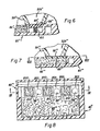
- FIG. 6 illustrates another embodiment, in which a rigid non-absorbent pad is used. Parts similar to those previously described bear the same reference numeral to which is added.
- filter 58 ⁇ is mounted over the bottom of each well, such as well 52b ⁇ , that is part of upper housing 59 ⁇ . Housing 59 ⁇ slides with respect to lower housing 60 ⁇ , having in an adjacent configuration, an absorbent material 66 ⁇ and a non-absorbent pad 68 ⁇ for each well.
- pad 68 ⁇ is relatively rigid.
- a spring 100 is used to bias pad 68 ⁇ upwardly with a force equivalent to about 3 cm of water as a liquid head of pressure. (2.5 cm is the maximum height of liquid used in the wells.)
- the corners of pad 68 ⁇ can be optionally rounded (not shown) to allow filter 58 ⁇ to cam pad 68 ⁇ down when filter 58 ⁇ is moved back over it, if such resealing is desired.
- An example of such a relatively rigid non-absorbent pad 68 ⁇ includes a hydrophobic plastic such as polyproplyene.
- a rigid non-absorbing pad can be used without the need for a spring 100 that is separate from the rest of the assembly.
- Such an embodiment is shown in Figures 7-9, wherein parts similar to those previously described bear the same reference numeral, to which the distinguishing mark (′′′) is appended.
- upper housing 59′′′ has a well 52b′′′ with a filter 58′′′, constructed as before.
- Lower housing 60′′′ has both an absorbent material 66′′′ and a rigid non-absorbent pad 68′′′ with respect to which filter 58′′′ slides, also as in the embodiment of Figure 6.
- the characteristic resilience of material 66′′′ is used to bias the rigid pad 68′′′ against filter 58′′′ with the necessary force.
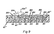
- material 66′′′ can be cut to have the shape shown in Fig. 9 even before pad 68′′′ is placed on top of material 66′′′.
- edges 210 of the portions 202 are preferably beveled.
- Figs. 7-9 can also be arranged as shown in Fig. 3B, to provide the relative sliding motion between the two housings.
Abstract
Description
- This invention relates to a construction of a test device that allows it to alternate between no-liquid flow, and liquid flow, through a filter, the filter being used to separate a reaction product from the reagents that provide the reaction product.
- Diagnostic devices have been provided in the past for conducting immunoreactions in one or more test wells to determine the qualitative existence of pregnancy or an infectious disease. Such devices commonly include a filter membrane at the bottom of the well to separate out free, unreacted immunoreagents, from complexed immunoreagents. (The former pass through the membrane.) Underneath such membranes is preferably located an absorbent material to absorb the liquid of the reaction mixture. It has been conventional in such devices to provide for control of liquid flow, so as to first retain the liquid in the well above the membrane for an incubation period, and then to allow flow through the membrane. Previously provided mechanisms for controlling the flow include an aperture in the housing for the absorbent material underneath, and seals for opening and closing the aperture. When the aperture is open, normal liquid wetting causes the liquid to flow though the membrane into the absorbent material. Such seals, although effective, require careful tolerances and assembly techniques, so as to insure the apertures are normally closed, while at the same time are openable using manual forces easily available to the user.
- Thus, a problem prior to this invention has been to provide liquid flow control for such devices without requiring such high tolerance, while at the same time allowing easy use by the operator.
- A recent development towards this end is that described in U.S. Patent 4,734,262 by Bagshawe. In this device, a non-absorbent seal is provided at the bottom of the well, between the opening in the well and the filter membrane that is combined with an absorbent material. The device is constructed to provide relative movement in the form of reciprocation, between the seal and the opening, but not between the seal and the filter membrane. That is, both the seal and membrane are caused to deflect away from the opening, such as by applying pressure to the top chamber, allowing liquid to pour out onto the filter membrane. Such a construction has several disadvantages. One is that the seal covers the surface of the filter membrane at the top, thus decreasing the area available for filtration, and most importantly, it prevents the filter from being observed through the opening for a detectable change indicative of a positive reaction. A second disadvantage is a requirement that there be a positive driving pressure to open the seal. This requires an auxiliary instrument, such as a vacuum source, besides what can be done using just the operator's own manipulation.
- The problems of this invention are addressed by a diagnostic device with flow control means that avoid the above-noted problems concerning tolerances and difficulties of pressurizing and reading.
- More specifically, the above problems are addressed by a test device useful for conducting a reaction, the device comprising a) a well configured to confine temporarily a liquid patient sample admixed with at least one reagent, to provide the reaction, b) a filter at the bottom of the well with pores effective to pass free, unreacted reagent but not complexed or reacted reagent, and c) an absorbent material underneath the filter effective to draw off liquid in the well after the reaction. The device is characterized in that it further includes d) a non-absorbent pad underneath the filter, adjacent to the absorbent material, and e) means for moving the filter and the absorbent material relative to each other, and the filter and the pad relative to each other, between two positions, one in which the filter contacts the non-absorbent pad and the other in which the filter contacts the absorbent material.
- It is an advantageous feature of the invention that a liquid testing device is provided with a liquid-confining well, a filter, and an absorbent material underneath, that allows flow or no flow of liquid through the filter without the use of vent seals of carefully controlled tolerances.
- It is another advantageous feature of the invention that such a liquid testing device is provided that allows filtering of the liquid to occur without having to apply a pressure differential across the filter to open the filter to flow.
- It is a related advantageous feature of the invention that such a device is provided wherein the results are easily read from a color change on the filter, after flow is readily initiated by the user.
- The present invention will now be described by way of example with reference to the accompanying drawings in which:
- Figures 1A and 1B are fragmentary sectional views of a prior art device, requiring a pressure differential to be applied across the filter to cause liquid flow to occur through the filter;
- Figure 2 is a plan view of a device constructed in accord with the present invention;
- Figure 3A is a sectional view of the device of Figure 2, taken along the line IIIA - IIIA of Figure 4;
- Figure 3B is a sectional view similar to Figure 3A but of a slightly different embodiment;
- Figure 4 is a sectional plan view, taken along the line IV - IV of Figure 3A;
- Figure 5 is an exploded plan view, partially broken away, of a comparative example;
- Figures 6 and 7 are fragmentary sectional views similar to that of Figures 3A and 3B, but illustrating alternate embodiments;
- Figure 8 is a section view taken generally along the line VIII - VIII of Figure 7; and
- Figure 9 is a section view taken generally along the line IX - IX of Figure 8.
- The invention is described herein in the context of the preferred embodiments, in which the device has three pairs of upper/lower compartments, to immunoassay a) the patient sample, b) a positive control and c) a negative control, all more or less simultaneously. The filters are shown as sliding between two positions. In addition, aspects of the invention are useful with only a single pair of compartments, and with any kind of reaction and any form of relative movement between the filter and its absorbent material.
- The actual chemistries of the assay are not described in detail, primarily because the mechanics of the device are applicable to any, or even no, chemistry, provided it is appropriate that flow not take place instantaneously into the liquid-receiving compartment.
- In the most preferred embodiment, the chemistries provide for an immunoassay, in which there is separately received at three filters in three compartments, a patient antigen complexed with an antigen, a positive control for the complex so formed, and a negative control for the complex so formed, respectively, as is conventional.
- Figures 1A and 1B illustrate a
related device 10 provided by the prior art, specifically one taught by U.S. Patent No. 4,734,262 noted above. An upper compartment or well 12 has at the bottom of it, anaperture 14 that has mounted below it, anon-absorbent seal 16, that sits on the filter-absorbent material 18 held in place bymember 20. Liquid placed in well 12 will not pour into or throughmaterial 18 because seal 16 blocks it, Figure 1A. However, when a differential pressure is applied acrossmaterial 18, Figure 18, such as by a positive pressure applied to well 12 (arrow 22) or a vacuum applied tomaterial 18, both the seal andmaterial 18 pull away fromaperture 14 and liquid flow into the filter-absorbent material occurs,arrows 24. As noted above, the disadvantages of such a device are that the presence ofseal 16 prevents reading any color change through the top, and it requires the application of a pressure differential to unseatseal 16. - In accordance with the present invention, an improved
device 50 comprises, Figure 2, three upper compartments orwells bottom 53 of each well, Figure 3A, is covered with aporous filter 58 which will pass liquid through it unless such flow is blocked either by a liquid lock or some other means. Both the well and its filter are carried on anupper housing 59 having a slopedforward edge 61 and arear groove 63. - Below
housing 59 is alower housing member 60, Figures 2-4, having in an adjacent, and preferably contiguous relationship, both anabsorbent material 66 and a non-absorbent seal orpad 68, Figure 4. Thefootprint 58 of the filter of each well 52a, 52b and 52c, is shown as contactingpad 68, Figure 4, before each well moves to where the filter contacts the adjacentabsorbent material 66. The height "h", Figure 3A, of bothmaterial 66 and thepad 68 is such as to compressmaterial 66 orpad 68 slightly, when filter 58 contacts either one. - The
material 66 andpads 68 are held withinlower housing 60, as shown in Figure 4. Such lower housing has aforward edge 70 that optionally bears one ormore vent apertures 72, and atrack groove 74, Figure 3A, that accommodatesedge 61 ofupper housing 59 in a sliding relationship.Rearward portion 76 ofhousing 60 has alip 78 that slidably extends intogroove 63. Vertical ribs (not shown) can be located inhousing 60 between, e.g., eachmaterial 66, to keep them in place. - Thus, as is apparent,
upper housing 59 moves relative tolower housing 60 preferably by sliding with respect thereto. This in turn provides a sliding relationship betweenfilter 58 of each well, and both itsnon-absorbent pad 68 and itsabsorbent material 66. As shown in Figure 4, thefootprint 58 of the filter (shown in phantom) slides as perarrow 80, from contact withnon-absorbent pad 68, toabsorbent material 66. That is, each well goes from a non-liquid-flow condition to a liquid-flowing condition, respectively, sinceapertures 72 insure there is no liquid lock. The word "closed" can be printed at 85 on the top ofhousing 60, Figure 2, to inform the user that, when configured as shown in Figure 2, the wells are closed off from flow. A printing of the word "open" (not shown) is useful at theother end 87 of the top ofhousing 60. - Other sliding motions are useful as well, for example, one in which the upper housing rotates with respect to the lower housing (not shown).
- Yet another useful sliding motion is one in which the lower housing slides relative to the upper housing, which is kept stationary. Such an alternative embodiment appears in Fig. 3B, in which parts similar to those previously described bear the same reference numerals, to which the distinguishing suffix (′) (prime) is attached. Thus,
device 50′ comprises anupper housing 59′ and alower housing 60′.Housing 59′ includes wells such aswell 52b′, and filter 58′, andhousing 60′ housesabsorbent material 66′ andnon-absorbent pad 68′, all constructed as described above. However, in this embodimentupper housing 59′ remains stationary by reason of its foursupports 89 that are attached, for example, at the four corners of such housing.Housing 59′ also includes alip 61′ that fits in agroove 74′ provided inhousing 60′, and arear groove 63′ that accommodateslip 78′ ofhousing 60′.Housing 60′ is slung to slide withingroove 63′ and onlip 61′ as a track support, in and out of the plane of Fig. 3B. - Useful materials for either embodiment include the following:
Filters 58 can be polyamides, such as nylon, and for example nylon-66 microporous membranes manufactured under the tradenames BIODYNE A or ULTRIPOR N-66 by Pall Corporation. Most preferably, the membranes are precoated (prior to use) with one or more water-soluble proteins, such as casein derivatives obtained from acylation, alkylation or sulfonylation of the casein. Various optional additional treatments can be given to the filter upper surface during or before assembly. -
Absorbent material 66 can be any bibulous material, having a sufficient pore volume to soak up about 2 cc of liquid. Useful materials include cellulose acetate, cotton, and rayon. - As noted,
pads 68 are selected from non-absorbent materials, such as resilient neoprene laminated with a hydrophobic plastic, for example, polypropylene. The resiliency is selected to allowfilter 58 to compresspad 68 with sufficient pressure as to withstand about 3 cm of water as a liquid head of pressure, without leaking. Such compression does not significantly interfere with theupper housing 59 being easily slid by a user, relative tolower housing 60, by simply using finger pressure. - As a result, the devices of the invention are particularly useful to provide an immunoreaction within one or all of the wells, between an immunoreagent (such as labeled antibodies) that is pre-applied or added to the well, and the patient's sample. When
housing 59 is slid to the open position (by sliding leftward, Figure 2), the liquid is then free to flow into the absorbent material underneath, carrying with it unreacted (uncomplexed) immunoreagent. However, complexed immunoreagent remains behind on the filter, either because of its size or because a sandwich has formed using beaded antibodies which will not pass through the filter. The labeled antibodies so trapped on the filter are then caused to react to produce a detectable signal. - Figure 5 illustrates a comparative example, wherein no movement occurs between the
filter 124 and itsabsorbent material 128. Instead, those parts occupy a fixed relationship and aslide valve 150 acts to open orclose apertures 144, using a compressed elastomeric material inside valve 150 (not shown). Although such a device works well, care is needed in the selection of materials and in the manufacture of related dimensions to insure thatvalve 150 can be moved by finger pressure. In contrast, less care need be given to the tolerances used to assemblefilter 58 of the present invention, in sliding contact withpad 68 orabsorbent material 66. - Figure 6 illustrates another embodiment, in which a rigid non-absorbent pad is used. Parts similar to those previously described bear the same reference numeral to which is added. Thus, as in the previous embodiment, filter 58˝ is mounted over the bottom of each well, such as
well 52b˝, that is part ofupper housing 59˝.Housing 59˝ slides with respect tolower housing 60˝, having in an adjacent configuration, anabsorbent material 66˝ and anon-absorbent pad 68˝ for each well. Unlike the previous embodiment, however, pad 68˝ is relatively rigid. To insure that it seats againstfilter 58˝ with sufficient pressure as to prevent leakage, aspring 100 is used to biaspad 68˝ upwardly with a force equivalent to about 3 cm of water as a liquid head of pressure. (2.5 cm is the maximum height of liquid used in the wells.) The corners ofpad 68˝ can be optionally rounded (not shown) to allowfilter 58˝ tocam pad 68˝ down whenfilter 58˝ is moved back over it, if such resealing is desired. - An example of such a relatively rigid
non-absorbent pad 68˝ includes a hydrophobic plastic such as polyproplyene. - A rigid non-absorbing pad can be used without the need for a
spring 100 that is separate from the rest of the assembly. Such an embodiment is shown in Figures 7-9, wherein parts similar to those previously described bear the same reference numeral, to which the distinguishing mark (‴) is appended. - Thus, in Figure 7, as in the embodiment of Figure 6,
upper housing 59‴ has a well 52b‴ with afilter 58‴, constructed as before.Lower housing 60‴ has both anabsorbent material 66‴ and arigid non-absorbent pad 68‴ with respect to whichfilter 58‴ slides, also as in the embodiment of Figure 6. However, in this embodiment the characteristic resilience ofmaterial 66‴ is used to bias therigid pad 68‴ againstfilter 58‴ with the necessary force. In addition, Figure 9,material 66‴ has a tendency to protrude at 190 intoapertures 200 ofpad 68‴, thus providing the desired contiguous location of the absorbent material immediately adjacent toportions 202 of the pad on which the footprint offilter 58‴ presses, Figure 8. As a result, when well 52a‴ moves as perarrow 204, Figure 9, it goes from its closed contact withportion 202 ofpad 68‴, to the "open" contact withportions 190 ofmaterial 66‴. - Alternatively,
material 66‴ can be cut to have the shape shown in Fig. 9 even beforepad 68‴ is placed on top ofmaterial 66‴. - To allow reclosing of the wells by movement back onto
pad 68‴, edges 210 of theportions 202 are preferably beveled. - The embodiment of Figs. 7-9 can also be arranged as shown in Fig. 3B, to provide the relative sliding motion between the two housings.
Claims (13)
characterized in that said device further includes d) a non-absorbent pad underneath said filter, adjacent to said absorbent material, and e) means for moving said filter and said absorbent material relative to each other, and said filter and said pad relative to each other, between two positions, one in which said filter contacts said non-absorbent pad and the other in which said filter contacts said absorbent material.
characterized in that said device further includes a non-absorbent pad underneath said filter, and wherein said liquid-controlling means comprise means for providing relative sliding movement between said filter and said pad and said absorbent material, to provide contact of said filter with either said non-absorbing pad or said absorbent material, so that proper alternating conditions of no flow or flow occur.
Applications Claiming Priority (2)
| Application Number | Priority Date | Filing Date | Title |
|---|---|---|---|
| US07/224,831 US4877586A (en) | 1988-07-27 | 1988-07-27 | Sliding test device for assays |
| US224831 | 1988-07-27 |
Publications (3)
| Publication Number | Publication Date |
|---|---|
| EP0353025A2 true EP0353025A2 (en) | 1990-01-31 |
| EP0353025A3 EP0353025A3 (en) | 1991-03-20 |
| EP0353025B1 EP0353025B1 (en) | 1993-05-12 |
Family
ID=22842413
Family Applications (1)
| Application Number | Title | Priority Date | Filing Date |
|---|---|---|---|
| EP89307548A Expired - Lifetime EP0353025B1 (en) | 1988-07-27 | 1989-07-25 | Sliding test device for assays |
Country Status (5)
| Country | Link |
|---|---|
| US (1) | US4877586A (en) |
| EP (1) | EP0353025B1 (en) |
| JP (1) | JPH0274863A (en) |
| CA (1) | CA1332911C (en) |
| DE (1) | DE68906479D1 (en) |
Cited By (7)
| Publication number | Priority date | Publication date | Assignee | Title |
|---|---|---|---|---|
| EP0458198A2 (en) * | 1990-05-22 | 1991-11-27 | Millipore Corporation | Flow through assay apparatus |
| WO1993013856A1 (en) * | 1992-01-18 | 1993-07-22 | Genera Technologies Limtied | Assay apparatus and method |
| EP0635721A1 (en) * | 1993-07-23 | 1995-01-25 | Whatman Inc. | Solid phase extraction device |
| WO1996012561A1 (en) * | 1994-10-25 | 1996-05-02 | Sippican, Inc. | Chemical detector |
| WO1999028038A1 (en) * | 1997-11-28 | 1999-06-10 | Cortecs Diagnostics Limited | Device and apparatus for conducting an assay |
| WO2000000830A1 (en) * | 1998-06-29 | 2000-01-06 | Sension, Biologische Detektions- Und Schnelltestsysteme Gmbh | Combined device for simultaneously conducting immunofiltration tests |
| WO2000076663A1 (en) * | 1999-06-10 | 2000-12-21 | Provalis Diagnostics Limited | Apparatus, instrument and device for conducting an assay |
Families Citing this family (48)
| Publication number | Priority date | Publication date | Assignee | Title |
|---|---|---|---|---|
| US4948561A (en) * | 1989-02-09 | 1990-08-14 | Eastman Kodak Company | Multiple level filter device and kit containing same |
| US5114350A (en) * | 1989-03-08 | 1992-05-19 | Cholestech Corporation | Controlled-volume assay apparatus |
| US5110724A (en) * | 1990-04-02 | 1992-05-05 | Cholestech Corporation | Multi-analyte assay device |
| US5258163A (en) * | 1990-04-14 | 1993-11-02 | Boehringer Mannheim Gmbh | Test carrier for analysis of fluids |
| US5869345A (en) * | 1991-05-29 | 1999-02-09 | Smithkline Diagnostics, Inc. | Opposable-element assay device employing conductive barrier |
| US5468648A (en) * | 1991-05-29 | 1995-11-21 | Smithkline Diagnostics, Inc. | Interrupted-flow assay device |
| US5998220A (en) | 1991-05-29 | 1999-12-07 | Beckman Coulter, Inc. | Opposable-element assay devices, kits, and methods employing them |
| US5607863A (en) * | 1991-05-29 | 1997-03-04 | Smithkline Diagnostics, Inc. | Barrier-controlled assay device |
| US6168956B1 (en) | 1991-05-29 | 2001-01-02 | Beckman Coulter, Inc. | Multiple component chromatographic assay device |
| US5877028A (en) | 1991-05-29 | 1999-03-02 | Smithkline Diagnostics, Inc. | Immunochromatographic assay device |
| DE4132743A1 (en) * | 1991-10-02 | 1993-04-08 | Boehringer Mannheim Gmbh | TEST CARRIER FOR THE ANALYSIS OF LIQUIDS |
| US6156270A (en) | 1992-05-21 | 2000-12-05 | Biosite Diagnostics, Inc. | Diagnostic devices and apparatus for the controlled movement of reagents without membranes |
| US7524456B1 (en) | 1992-05-21 | 2009-04-28 | Biosite Incorporated | Diagnostic devices for the controlled movement of reagents without membranes |
| US6767510B1 (en) * | 1992-05-21 | 2004-07-27 | Biosite, Inc. | Diagnostic devices and apparatus for the controlled movement of reagents without membranes |
| US6905882B2 (en) * | 1992-05-21 | 2005-06-14 | Biosite, Inc. | Diagnostic devices and apparatus for the controlled movement of reagents without membranes |
| US5589344A (en) | 1994-06-15 | 1996-12-31 | Johnson & Johnson Clinical Diagnostics, Inc. | Test kit and method for competitive specific binding assay |
| US5770086A (en) * | 1996-01-25 | 1998-06-23 | Eureka| Science Corp. | Methods and apparatus using hydrogels |
| US5879951A (en) | 1997-01-29 | 1999-03-09 | Smithkline Diagnostics, Inc. | Opposable-element assay device employing unidirectional flow |
| US5939252A (en) | 1997-05-09 | 1999-08-17 | Lennon; Donald J. | Detachable-element assay device |
| AUPP103497A0 (en) | 1997-12-19 | 1998-01-15 | Panbio Pty Ltd | Assay apparatus |
| GB0021887D0 (en) * | 2000-09-06 | 2000-10-18 | Provalis Diagnostics Ltd | Assay device |
| US6372516B1 (en) | 2000-09-07 | 2002-04-16 | Sun Biomedical Laboratories, Inc. | Lateral flow test device |
| AU2002331408B2 (en) * | 2001-08-20 | 2008-05-08 | Proteome Systems Ltd | Diagnostic testing process and apparatus |
| US7102752B2 (en) * | 2001-12-11 | 2006-09-05 | Kimberly-Clark Worldwide, Inc. | Systems to view and analyze the results from diffraction-based diagnostics |
| US7098041B2 (en) | 2001-12-11 | 2006-08-29 | Kimberly-Clark Worldwide, Inc. | Methods to view and analyze the results from diffraction-based diagnostics |
| JP4551660B2 (en) * | 2001-12-12 | 2010-09-29 | プロテオム システムズ リミテッド | Diagnostic inspection method |
| US8367013B2 (en) | 2001-12-24 | 2013-02-05 | Kimberly-Clark Worldwide, Inc. | Reading device, method, and system for conducting lateral flow assays |
| US20030119203A1 (en) | 2001-12-24 | 2003-06-26 | Kimberly-Clark Worldwide, Inc. | Lateral flow assay devices and methods for conducting assays |
| ATE309544T1 (en) | 2002-04-09 | 2005-11-15 | Cholestech Corp | METHOD AND DEVICE FOR QUANTIFYING HIGH DENSITY LIPOPROTEIN-CHOLESTEROL |
| US7314763B2 (en) | 2002-08-27 | 2008-01-01 | Kimberly-Clark Worldwide, Inc. | Fluidics-based assay devices |
| US7432105B2 (en) | 2002-08-27 | 2008-10-07 | Kimberly-Clark Worldwide, Inc. | Self-calibration system for a magnetic binding assay |
| US7285424B2 (en) | 2002-08-27 | 2007-10-23 | Kimberly-Clark Worldwide, Inc. | Membrane-based assay devices |
| CN1318142C (en) * | 2002-10-11 | 2007-05-30 | Zbx公司 | Diagnostic devices |
| US7781172B2 (en) | 2003-11-21 | 2010-08-24 | Kimberly-Clark Worldwide, Inc. | Method for extending the dynamic detection range of assay devices |
| US7247500B2 (en) | 2002-12-19 | 2007-07-24 | Kimberly-Clark Worldwide, Inc. | Reduction of the hook effect in membrane-based assay devices |
| US20040197819A1 (en) | 2003-04-03 | 2004-10-07 | Kimberly-Clark Worldwide, Inc. | Assay devices that utilize hollow particles |
| US7851209B2 (en) | 2003-04-03 | 2010-12-14 | Kimberly-Clark Worldwide, Inc. | Reduction of the hook effect in assay devices |
| US20050112703A1 (en) | 2003-11-21 | 2005-05-26 | Kimberly-Clark Worldwide, Inc. | Membrane-based lateral flow assay devices that utilize phosphorescent detection |
| US7713748B2 (en) | 2003-11-21 | 2010-05-11 | Kimberly-Clark Worldwide, Inc. | Method of reducing the sensitivity of assay devices |
| US7943395B2 (en) | 2003-11-21 | 2011-05-17 | Kimberly-Clark Worldwide, Inc. | Extension of the dynamic detection range of assay devices |
| US7943089B2 (en) | 2003-12-19 | 2011-05-17 | Kimberly-Clark Worldwide, Inc. | Laminated assay devices |
| US7521226B2 (en) | 2004-06-30 | 2009-04-21 | Kimberly-Clark Worldwide, Inc. | One-step enzymatic and amine detection technique |
| JP2007003412A (en) * | 2005-06-24 | 2007-01-11 | Sekisui Chem Co Ltd | Biological measuring method |
| US8133741B2 (en) | 2005-10-26 | 2012-03-13 | General Electric Company | Methods and systems for delivery of fluidic samples to sensor arrays |
| US7723120B2 (en) * | 2005-10-26 | 2010-05-25 | General Electric Company | Optical sensor array system and method for parallel processing of chemical and biochemical information |
| DE602008002825D1 (en) | 2007-01-09 | 2010-11-11 | Cholestech Corp | DEVICE AND METHOD FOR MEASURING THE LDL ASSOCIATED CHOLESTEROL |
| US7883898B2 (en) * | 2007-05-07 | 2011-02-08 | General Electric Company | Method and apparatus for measuring pH of low alkalinity solutions |
| CN110168366A (en) * | 2017-01-04 | 2019-08-23 | 新加坡科技研究局 | The vertical streaming system of sieving for the bioassay based on particle |
Citations (2)
| Publication number | Priority date | Publication date | Assignee | Title |
|---|---|---|---|---|
| US4558013A (en) * | 1983-04-08 | 1985-12-10 | Mast Immunosystems, Ltd. | Calibrated reaction measurement system |
| US4734262A (en) * | 1983-04-29 | 1988-03-29 | Bagshawe Kenneth D | Reaction mixture handling device |
Family Cites Families (2)
| Publication number | Priority date | Publication date | Assignee | Title |
|---|---|---|---|---|
| IT1006557B (en) * | 1971-09-08 | 1976-10-20 | Bagshawe Kenneth Dawson | REACTION CELL PARTICULARLY USEFUL IN RADIOIMMUNITY TESTS |
| US4246339A (en) * | 1978-11-01 | 1981-01-20 | Millipore Corporation | Test device |
-
1988
- 1988-07-27 US US07/224,831 patent/US4877586A/en not_active Expired - Lifetime
-
1989
- 1989-03-15 CA CA000593735A patent/CA1332911C/en not_active Expired - Fee Related
- 1989-07-25 DE DE8989307548T patent/DE68906479D1/en not_active Expired - Lifetime
- 1989-07-25 JP JP1192455A patent/JPH0274863A/en active Pending
- 1989-07-25 EP EP89307548A patent/EP0353025B1/en not_active Expired - Lifetime
Patent Citations (2)
| Publication number | Priority date | Publication date | Assignee | Title |
|---|---|---|---|---|
| US4558013A (en) * | 1983-04-08 | 1985-12-10 | Mast Immunosystems, Ltd. | Calibrated reaction measurement system |
| US4734262A (en) * | 1983-04-29 | 1988-03-29 | Bagshawe Kenneth D | Reaction mixture handling device |
Cited By (9)
| Publication number | Priority date | Publication date | Assignee | Title |
|---|---|---|---|---|
| EP0458198A2 (en) * | 1990-05-22 | 1991-11-27 | Millipore Corporation | Flow through assay apparatus |
| EP0458198A3 (en) * | 1990-05-22 | 1992-11-19 | Millipore Corporation | Flow through assay apparatus and process |
| WO1993013856A1 (en) * | 1992-01-18 | 1993-07-22 | Genera Technologies Limtied | Assay apparatus and method |
| EP0635721A1 (en) * | 1993-07-23 | 1995-01-25 | Whatman Inc. | Solid phase extraction device |
| WO1996012561A1 (en) * | 1994-10-25 | 1996-05-02 | Sippican, Inc. | Chemical detector |
| WO1999028038A1 (en) * | 1997-11-28 | 1999-06-10 | Cortecs Diagnostics Limited | Device and apparatus for conducting an assay |
| US6300142B1 (en) | 1997-11-28 | 2001-10-09 | Provalis Diagnostics Ltd | Device and apparatus for conducting an assay |
| WO2000000830A1 (en) * | 1998-06-29 | 2000-01-06 | Sension, Biologische Detektions- Und Schnelltestsysteme Gmbh | Combined device for simultaneously conducting immunofiltration tests |
| WO2000076663A1 (en) * | 1999-06-10 | 2000-12-21 | Provalis Diagnostics Limited | Apparatus, instrument and device for conducting an assay |
Also Published As
| Publication number | Publication date |
|---|---|
| CA1332911C (en) | 1994-11-08 |
| DE68906479D1 (en) | 1993-06-17 |
| JPH0274863A (en) | 1990-03-14 |
| EP0353025A3 (en) | 1991-03-20 |
| EP0353025B1 (en) | 1993-05-12 |
| US4877586A (en) | 1989-10-31 |
Similar Documents
| Publication | Publication Date | Title |
|---|---|---|
| EP0353025B1 (en) | Sliding test device for assays | |
| US4797260A (en) | Antibody testing system | |
| JP2513740B2 (en) | Method and apparatus for fecal occult blood sampling and testing | |
| US4948561A (en) | Multiple level filter device and kit containing same | |
| JP2543871B2 (en) | Method and apparatus for fecal occult blood sampling and testing | |
| US5283039A (en) | Multi-well filtration apparatus | |
| US5147606A (en) | Self-metering fluid analysis device | |
| FI78361B (en) | ANORDING FOR CHEMICAL ANALYZER AND ANALYZING. | |
| US5077012A (en) | Device for detecting disease markers | |
| US4734262A (en) | Reaction mixture handling device | |
| EP0991928A2 (en) | Rapid flow-through binding assay apparatus and method | |
| GB2086761A (en) | Fractionation system for biological fluids | |
| CA2344544A1 (en) | Analytical test device and method of use | |
| US20060193746A1 (en) | Multiple analyte assay devices | |
| EP1554571A2 (en) | In line test device and methods of use | |
| JPH06109606A (en) | Sample collecting and analyzing apparatus | |
| US5227290A (en) | Method for conducting diagnostic assays | |
| US4976926A (en) | Vacuum diagnostic device | |
| AU589286B2 (en) | Improved apparatus and process for immunoassays | |
| US4792398A (en) | Manual vacuum filtration device | |
| GB2139519A (en) | Reaction-chamber and filter for chemical analysis | |
| US5419870A (en) | Antibody testing system | |
| US4921677A (en) | Sliding valve for vent of liquid collecting compartment | |
| EP0308231B1 (en) | Liquid-collecting device | |
| JPH06331625A (en) | Stool occult blood discriminating device |
Legal Events
| Date | Code | Title | Description |
|---|---|---|---|
| PUAI | Public reference made under article 153(3) epc to a published international application that has entered the european phase |
Free format text: ORIGINAL CODE: 0009012 |
|
| AK | Designated contracting states |
Kind code of ref document: A2 Designated state(s): CH DE FR GB IT LI SE |
|
| PUAL | Search report despatched |
Free format text: ORIGINAL CODE: 0009013 |
|
| AK | Designated contracting states |
Kind code of ref document: A3 Designated state(s): CH DE FR GB IT LI SE |
|
| 17P | Request for examination filed |
Effective date: 19910807 |
|
| 17Q | First examination report despatched |
Effective date: 19921009 |
|
| GRAA | (expected) grant |
Free format text: ORIGINAL CODE: 0009210 |
|
| AK | Designated contracting states |
Kind code of ref document: B1 Designated state(s): CH DE FR GB IT LI SE |
|
| PG25 | Lapsed in a contracting state [announced via postgrant information from national office to epo] |
Ref country code: IT Free format text: LAPSE BECAUSE OF FAILURE TO SUBMIT A TRANSLATION OF THE DESCRIPTION OR TO PAY THE FEE WITHIN THE PRE;WARNING: LAPSES OF ITALIAN PATENTS WITH EFFECTIVE DATE BEFORE 2007 MAY HAVE OCCURRED AT ANY TIME BEFORE 2007. THE CORRECT EFFECTIVE DATE MAY BE DIFFERENT FROM THE ONE RECORDED.SCRIBED TIME-LIMIT Effective date: 19930512 Ref country code: DE Effective date: 19930512 Ref country code: CH Effective date: 19930512 Ref country code: SE Effective date: 19930512 Ref country code: LI Effective date: 19930512 |
|
| REF | Corresponds to: |
Ref document number: 68906479 Country of ref document: DE Date of ref document: 19930617 |
|
| REG | Reference to a national code |
Ref country code: CH Ref legal event code: PL |
|
| ET | Fr: translation filed | ||
| REG | Reference to a national code |
Ref country code: GB Ref legal event code: 732E |
|
| PGFP | Annual fee paid to national office [announced via postgrant information from national office to epo] |
Ref country code: FR Payment date: 19970709 Year of fee payment: 9 |
|
| PGFP | Annual fee paid to national office [announced via postgrant information from national office to epo] |
Ref country code: GB Payment date: 19970716 Year of fee payment: 9 |
|
| PG25 | Lapsed in a contracting state [announced via postgrant information from national office to epo] |
Ref country code: GB Free format text: LAPSE BECAUSE OF NON-PAYMENT OF DUE FEES Effective date: 19980725 |
|
| GBPC | Gb: european patent ceased through non-payment of renewal fee |
Effective date: 19980725 |
|
| PG25 | Lapsed in a contracting state [announced via postgrant information from national office to epo] |
Ref country code: FR Free format text: LAPSE BECAUSE OF NON-PAYMENT OF DUE FEES Effective date: 19990331 |
|
| REG | Reference to a national code |
Ref country code: FR Ref legal event code: ST |
|
| PLBE | No opposition filed within time limit |
Free format text: ORIGINAL CODE: 0009261 |
|
| STAA | Information on the status of an ep patent application or granted ep patent |
Free format text: STATUS: NO OPPOSITION FILED WITHIN TIME LIMIT |