EP0352017A1 - Fastener - Google Patents
Fastener Download PDFInfo
- Publication number
- EP0352017A1 EP0352017A1 EP89307094A EP89307094A EP0352017A1 EP 0352017 A1 EP0352017 A1 EP 0352017A1 EP 89307094 A EP89307094 A EP 89307094A EP 89307094 A EP89307094 A EP 89307094A EP 0352017 A1 EP0352017 A1 EP 0352017A1
- Authority
- EP
- European Patent Office
- Prior art keywords
- tab
- parts
- strip
- piece
- pieces
- Prior art date
- Legal status (The legal status is an assumption and is not a legal conclusion. Google has not performed a legal analysis and makes no representation as to the accuracy of the status listed.)
- Withdrawn
Links
Images

Classifications
-
- A—HUMAN NECESSITIES
- A44—HABERDASHERY; JEWELLERY
- A44B—BUTTONS, PINS, BUCKLES, SLIDE FASTENERS, OR THE LIKE
- A44B13/00—Hook or eye fasteners
- A44B13/0005—Hook or eye fasteners characterised by their material
- A44B13/0023—Hook or eye fasteners characterised by their material made of plastics
-
- A—HUMAN NECESSITIES
- A44—HABERDASHERY; JEWELLERY
- A44B—BUTTONS, PINS, BUCKLES, SLIDE FASTENERS, OR THE LIKE
- A44B13/00—Hook or eye fasteners
- A44B13/0029—Hook or eye fasteners characterised by their way of fastening to the support
- A44B13/0047—Hook or eye fasteners characterised by their way of fastening to the support welded or moulded
-
- A—HUMAN NECESSITIES
- A44—HABERDASHERY; JEWELLERY
- A44B—BUTTONS, PINS, BUCKLES, SLIDE FASTENERS, OR THE LIKE
- A44B13/00—Hook or eye fasteners
- A44B13/0052—Strips of hook or eye fasteners
-
- A—HUMAN NECESSITIES
- A44—HABERDASHERY; JEWELLERY
- A44B—BUTTONS, PINS, BUCKLES, SLIDE FASTENERS, OR THE LIKE
- A44B18/00—Fasteners of the touch-and-close type; Making such fasteners
- A44B18/0003—Fastener constructions
- A44B18/0007—Fastener constructions in which each part has similar elements
-
- Y—GENERAL TAGGING OF NEW TECHNOLOGICAL DEVELOPMENTS; GENERAL TAGGING OF CROSS-SECTIONAL TECHNOLOGIES SPANNING OVER SEVERAL SECTIONS OF THE IPC; TECHNICAL SUBJECTS COVERED BY FORMER USPC CROSS-REFERENCE ART COLLECTIONS [XRACs] AND DIGESTS
- Y10—TECHNICAL SUBJECTS COVERED BY FORMER USPC
- Y10S—TECHNICAL SUBJECTS COVERED BY FORMER USPC CROSS-REFERENCE ART COLLECTIONS [XRACs] AND DIGESTS
- Y10S24/00—Buckles, buttons, clasps
- Y10S24/30—Separable-fastener or required component thereof
- Y10S24/38—Each mating member having similarly shaped, sized, and operated interlocking face
- Y10S24/40—Each mating member having similarly shaped, sized, and operated interlocking face including elongated face having varying, parallel cross sections throughout its length
-
- Y—GENERAL TAGGING OF NEW TECHNOLOGICAL DEVELOPMENTS; GENERAL TAGGING OF CROSS-SECTIONAL TECHNOLOGIES SPANNING OVER SEVERAL SECTIONS OF THE IPC; TECHNICAL SUBJECTS COVERED BY FORMER USPC CROSS-REFERENCE ART COLLECTIONS [XRACs] AND DIGESTS
- Y10—TECHNICAL SUBJECTS COVERED BY FORMER USPC
- Y10T—TECHNICAL SUBJECTS COVERED BY FORMER US CLASSIFICATION
- Y10T24/00—Buckles, buttons, clasps, etc.
- Y10T24/14—Bale and package ties, hose clamps
- Y10T24/1457—Metal bands
- Y10T24/148—End-to-end integral band end connection
-
- Y—GENERAL TAGGING OF NEW TECHNOLOGICAL DEVELOPMENTS; GENERAL TAGGING OF CROSS-SECTIONAL TECHNOLOGIES SPANNING OVER SEVERAL SECTIONS OF THE IPC; TECHNICAL SUBJECTS COVERED BY FORMER USPC CROSS-REFERENCE ART COLLECTIONS [XRACs] AND DIGESTS
- Y10—TECHNICAL SUBJECTS COVERED BY FORMER USPC
- Y10T—TECHNICAL SUBJECTS COVERED BY FORMER US CLASSIFICATION
- Y10T24/00—Buckles, buttons, clasps, etc.
- Y10T24/45—Separable-fastener or required component thereof [e.g., projection and cavity to complete interlock]
- Y10T24/45152—Each mating member having similarly shaped, sized, and operated interlocking or intermeshable face
- Y10T24/45215—Slot and tab or tongue
Definitions
- the present invention provides a simple, inexpensive, effective, easily made fastener that makes firm partially self aligning engagement.
- a fastener comprising first and second pieces of stiff flexible polymeric sheet material, each piece having a plurality of aligned, equally spaced, similarly shaped and oriented, generally U shaped through slits.
- the slits define a row of tab-like parts of the piece and a surrounding main part of the piece.
- Each of the tab-like parts is bent along a bend line between the ends of the slit defining the tab-like part to project in the same direction out of the plane of the main part of the piece to define an opening through the piece beneath the tab-like part.
- the bend lines of the tab-like parts are parallel and extend transverse of the piece, and the main part and tab-like parts of the piece have opposed edge surfaces adjacent the opposite ends of the slits disposed at an included angle in the range of about 60 to 90 degrees (preferably about 70 to 80 degrees or 75 degrees) with respect to the adjacent bend line so that when the tab-like parts on each of the two pieces are simultaneously fully inserted through the openings in the other piece with the tab-like parts projecting generally in opposite directions, the edge surfaces of the tabs-like parts on one piece will make frictional engagement with the edge surfaces of the main part of the piece on the other to frictionally hold the pieces in releasable engagement.
- the pieces can be attached to different backing layers to be releasably attached by the fastener, with the surfaces of the pieces opposite that from which the tab-like portions project against the backing layer and the pieces attached to the backing layers at positions spaced from the row of tab-like parts so that when the pieces are engaged the tab-like parts of one of the pieces can move to positions between the other piece and the backing attached to the other piece.
- the backing layers are of rigid material, the pieces after engagement can only be disengaged by simultaneously sliding all of the tabs out of engagement with each other which takes an initial effort sufficient to overcome the frictional engagement between the surfaces.
- the pieces after engagement can be disengaged either by simultaneously sliding all of the tab-like portions out of engagement with each other which also takes an initial effort sufficient to overcome the frictional engagement between the surfaces, or by peeling the fastener portions apart one tab at a time, which peeling can facilitate separating the fastener portions particularly when they are used on garments, such as to fasten together tensioned elastic portions of garments such as brassieres.
- the pieces of the fastener can be cut from a strip of the stiff flexible polymeric material in which the tabs can be formed by passing the strip through a rotary die assembly.
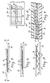
- FIG. 1 an elongate stiff flexible strip 10 of polymeric material (e.g., polypropylene in the range of about 0.025 to 0.051 centimeter (0.010 to 0.020 inch) thick) according to the present invention that is adapted to be cut into lengths to form releasably engageable pieces 11 of a fastener.
- polymeric material e.g., polypropylene in the range of about 0.025 to 0.051 centimeter (0.010 to 0.020 inch) thick
- the strip 10 and each piece 11 cut from the strip 10 has a plurality of equally spaced, aligned, similarly shaped and oriented, generally U shaped slits 12 along its length, which slits 12 define a row of tab-like parts 14 of the strip 10 or piece 11, and a surrounding main part 15 of the strip 10 or piece 11.
- Each of the tab-like parts 14 is bent along a bend line 16 between the ends of the slit 12 defining the tab-like part 14 in the same direction out of the plane of the main part 15 of the strip 10 or piece 11 to define an opening through the strip 10 or piece 11 beneath the tab-like part 14, and the slits 12 and tab-like parts 14 in the strip 10 of sheet material 10 can easily be formed by passing a strip of the sheet material through the nip of a pair of die wheels 13 as is illustrated in Figure 2.
- the bend lines 16 of the tab-like parts 14 are parallel and extend transverse of the strip 10 or piece 11 of sheet material such that an imaginary line perpendicular to one of the bend lines 16 and bisecting the adjacent tab-like part 14 will bisect all of the tab-like parts 14 along the strip 10 or piece 11.
- the tab-like parts 14 and the main part 15 of the strip 10 or piece 11 of sheet material have adjacent edge surfaces 18 and 20 respectively adjacent the opposite ends of the slits 12, which edge surfaces 18 and 20 are disposed at an included angle 22 (see Figure 1) in the range of about 60 to 90 degrees and preferably in the range of about 70 to 80 degrees or about 75 degrees with respect to the adjacent bend line 16.
- edge surfaces 18 and 20 With this orientation of the edge surfaces 18 and 20, when the tab-like parts 14 on each of two lengths or pieces 11 of the strip 10 of sheet material are simultaneously fully inserted through the openings in the other piece 11 of sheet material with the tab-like parts 14 projecting generally in opposite directions (as is sequentially illustrated in Figures 5-7 in which the pieces 11 being engaged are attached to backing layers 26), the edge surfaces 18 of the tab-like parts 14 on one piece 11 will make frictional engagement with the edge surfaces 20 of the main part 15 of the other piece 11 (see figure 8) to frictionally hold the pieces 11 in releasable engagement.
- the two pieces 11 are each attached to a different backing layer 26 as is illustrated in Figures 3 and 4 for one of the pieces 11 and in Figures 7-9 for two of the pieces 11.
- the pieces 11 are each attached along one of the surfaces of the backing layer 26 with the tab-like parts 14 of the piece projecting away from the backing layer 26, and the pieces are attached to the backing layer 26 (e.g., by staples, sewing stitches, adhesive or fusion as by ultrasonic welding) at positions 30 parallel to and spaced from the sides of the row of tab-like parts 14 so that when the pieces 11 are engaged, the tab-like parts 14 of one of the pieces 11 will be positioned between the other piece 11 and the backing 26 attached to the other piece, as can best be seen in Figure 9.
- the pieces 11 after engagement can only be disengaged by simultaneously sliding all of the tab-like parts 14 out of engagement with each other which takes an initial effort sufficient to overcome the frictional engagement between the surfaces 18 and 20.
- the pieces 11 after engagement can be disengaged either by simultaneously sliding all of the tab-like parts 14 out of engagement with each other (which also takes an initial effort sufficient to overcome the frictional engagement between the surfaces 18 and 20), or by peeling the pieces 11 apart from one end to disengage two tab-like parts 14 at a time as is illustrated in Figure 10. Such peeling can facilitate separating the pieces 11 particularly when they are used on garments.
- the tab-like parts 14 on a piece 11 made from 0.015 inch thick polypropylene can have a width along the bend line 16 of about 0.25 inch, an angle 22 of 75 degrees, a length at right angles to the bend line 16 of about 3/16 inch and a tip radius opposite the bend line 16 of about 3/32 inch about a center spaced at a right angle from the bend line 16 by about 3/64 inch, and the bend lines 16 of the tab-like parts 14 along the piece 11 can be spaced by about 9/16 inch.
Abstract
A strip (10) of polymeric sheet material adapted to cut into lengths to form releasably engageable pieces (11) of a fastener. The strip (14) has a row of tab-like parts (14) bent along bend lines (16) out of the plane of a main part (15) of the strip (10) to define an opening through the strip (10); and the main part (15) and tab-like parts (14) of the strip (10) have adjacent edge surfaces (18 and 20) disposed at an included angle in the range of about 60 to 90 degrees with respect to the adjacent bend line (16) so that when the tab-like parts (14) on each of two lengths of the strip (10) are simultaneously fully inserted through the openings in the other length with the tab-like parts (14) projecting generally in opposite directions, the edge surfaces (18 or 20) of the tab-like parts (14) on one length will make frictional engagement with the edge surfaces (18 or 20) of the main part of the strip (10) on the other to frictionally hold the lengths in releasable engagement.
Description
- The present invention relates to fasteners of the type having portions adapted for releasable engagement, and in one aspect to such fasteners in which both portions of the fasteners have essentially the same structure.
- The present invention provides a simple, inexpensive, effective, easily made fastener that makes firm partially self aligning engagement.
- According to the present invention there is provided a fastener comprising first and second pieces of stiff flexible polymeric sheet material, each piece having a plurality of aligned, equally spaced, similarly shaped and oriented, generally U shaped through slits. The slits define a row of tab-like parts of the piece and a surrounding main part of the piece. Each of the tab-like parts is bent along a bend line between the ends of the slit defining the tab-like part to project in the same direction out of the plane of the main part of the piece to define an opening through the piece beneath the tab-like part. The bend lines of the tab-like parts are parallel and extend transverse of the piece, and the main part and tab-like parts of the piece have opposed edge surfaces adjacent the opposite ends of the slits disposed at an included angle in the range of about 60 to 90 degrees (preferably about 70 to 80 degrees or 75 degrees) with respect to the adjacent bend line so that when the tab-like parts on each of the two pieces are simultaneously fully inserted through the openings in the other piece with the tab-like parts projecting generally in opposite directions, the edge surfaces of the tabs-like parts on one piece will make frictional engagement with the edge surfaces of the main part of the piece on the other to frictionally hold the pieces in releasable engagement.
- The pieces can be attached to different backing layers to be releasably attached by the fastener, with the surfaces of the pieces opposite that from which the tab-like portions project against the backing layer and the pieces attached to the backing layers at positions spaced from the row of tab-like parts so that when the pieces are engaged the tab-like parts of one of the pieces can move to positions between the other piece and the backing attached to the other piece. When the backing layers are of rigid material, the pieces after engagement can only be disengaged by simultaneously sliding all of the tabs out of engagement with each other which takes an initial effort sufficient to overcome the frictional engagement between the surfaces. When the backing layers are of flexible material, the pieces after engagement can be disengaged either by simultaneously sliding all of the tab-like portions out of engagement with each other which also takes an initial effort sufficient to overcome the frictional engagement between the surfaces, or by peeling the fastener portions apart one tab at a time, which peeling can facilitate separating the fastener portions particularly when they are used on garments, such as to fasten together tensioned elastic portions of garments such as brassieres.
- The pieces of the fastener can be cut from a strip of the stiff flexible polymeric material in which the tabs can be formed by passing the strip through a rotary die assembly.
- The present invention will be further described with reference to the accompanying drawing wherein like reference numerals refer to like parts in the several views, and wherein:
- Figure 1 is a fragmentary plan view of a strip of sheet material that is adapted to be cut into lengths to form releasably engageable portions of a fastener according to the present invention;
- Figure 2 is a schematic view illustrating the manufacture of the strip of sheet material of Figure 1;
- Figure 3 is a plan view illustrating the sheet material of Figure 1 attached to a backing;
- Figure 4 is a side view illustrating the sheet material of Figure 1 attached to a backing:
- Figures 5, 6, and 7 are side views sequentially illustrating engagement of two pieces of the sheet material of Figure 1 attached to a backing;
- Figure 8 is a sectional view taken approximately along line 8-8 of Figure 7;
- Figure 9 is an enlarged fragmentary sectional view taken approximately along line 9-9 of Figure 8; and
- Figure 10 is a side view illustrating partial separation of two engaged pieces of the sheet material of Figure 1 attached to a flexible backing.
- Referring now to the drawing, there is shown in Figure 1 an elongate stiff
flexible strip 10 of polymeric material (e.g., polypropylene in the range of about 0.025 to 0.051 centimeter (0.010 to 0.020 inch) thick) according to the present invention that is adapted to be cut into lengths to form releasablyengageable pieces 11 of a fastener. - The
strip 10 and eachpiece 11 cut from thestrip 10 has a plurality of equally spaced, aligned, similarly shaped and oriented, generally U shapedslits 12 along its length, which slits 12 define a row of tab-like parts 14 of thestrip 10 orpiece 11, and a surroundingmain part 15 of thestrip 10 orpiece 11. Each of the tab-like parts 14 is bent along abend line 16 between the ends of theslit 12 defining the tab-like part 14 in the same direction out of the plane of themain part 15 of thestrip 10 orpiece 11 to define an opening through thestrip 10 orpiece 11 beneath the tab-like part 14, and theslits 12 and tab-like parts 14 in thestrip 10 ofsheet material 10 can easily be formed by passing a strip of the sheet material through the nip of a pair ofdie wheels 13 as is illustrated in Figure 2. - The
bend lines 16 of the tab-like parts 14 are parallel and extend transverse of thestrip 10 orpiece 11 of sheet material such that an imaginary line perpendicular to one of thebend lines 16 and bisecting the adjacent tab-like part 14 will bisect all of the tab-like parts 14 along thestrip 10 orpiece 11. The tab-like parts 14 and themain part 15 of thestrip 10 orpiece 11 of sheet material haveadjacent edge surfaces slits 12, whichedge surfaces adjacent bend line 16. With this orientation of theedge surfaces like parts 14 on each of two lengths orpieces 11 of thestrip 10 of sheet material are simultaneously fully inserted through the openings in theother piece 11 of sheet material with the tab-like parts 14 projecting generally in opposite directions (as is sequentially illustrated in Figures 5-7 in which thepieces 11 being engaged are attached to backing layers 26), theedge surfaces 18 of the tab-like parts 14 on onepiece 11 will make frictional engagement with theedge surfaces 20 of themain part 15 of the other piece 11 (see figure 8) to frictionally hold thepieces 11 in releasable engagement. - Typically when the two
pieces 11 are used as a fastener they are each attached to adifferent backing layer 26 as is illustrated in Figures 3 and 4 for one of thepieces 11 and in Figures 7-9 for two of thepieces 11. Thepieces 11 are each attached along one of the surfaces of thebacking layer 26 with the tab-like parts 14 of the piece projecting away from thebacking layer 26, and the pieces are attached to the backing layer 26 (e.g., by staples, sewing stitches, adhesive or fusion as by ultrasonic welding) atpositions 30 parallel to and spaced from the sides of the row of tab-like parts 14 so that when thepieces 11 are engaged, the tab-like parts 14 of one of thepieces 11 will be positioned between theother piece 11 and thebacking 26 attached to the other piece, as can best be seen in Figure 9. - When the
backing layers 26 are of rigid material, thepieces 11 after engagement can only be disengaged by simultaneously sliding all of the tab-like parts 14 out of engagement with each other which takes an initial effort sufficient to overcome the frictional engagement between thesurfaces backing layers 26 are of flexible material, however, thepieces 11 after engagement can be disengaged either by simultaneously sliding all of the tab-like parts 14 out of engagement with each other (which also takes an initial effort sufficient to overcome the frictional engagement between thesurfaces 18 and 20), or by peeling thepieces 11 apart from one end to disengage two tab-like parts 14 at a time as is illustrated in Figure 10. Such peeling can facilitate separating thepieces 11 particularly when they are used on garments. - As one preferred example, the tab-
like parts 14 on apiece 11 made from 0.015 inch thick polypropylene can have a width along thebend line 16 of about 0.25 inch, anangle 22 of 75 degrees, a length at right angles to thebend line 16 of about 3/16 inch and a tip radius opposite thebend line 16 of about 3/32 inch about a center spaced at a right angle from thebend line 16 by about 3/64 inch, and thebend lines 16 of the tab-like parts 14 along thepiece 11 can be spaced by about 9/16 inch. - The present invention has now been described with reference to one embodiment thereof. It will be apparent to those skilled in the art that many changes can be made in the embodiment described without departing from the scope of the present invention. For example, while rounded tips on the tab-
like parts 14 are preferred for most uses, triangular tips may also be useful for some purposes; and other sheet materials such as metal or polymeric sheet material of polyester or nylon may be preferred for certain uses. Thus the scope of the present invention should not be limited to the structures described in this application, but only by structures described by the language of the claims and the equivalents of those structures.
Claims (13)
1. An elongate stiff flexible strip (10) of polymeric sheet material adapted to cut into lengths to form releasably engageable pieces (11) of a fastener, said strip (10) having a plurality of equally spaced, aligned, similarly shaped and oriented, generally U shaped slits (12) along its length, said slits (12) defining a row of tab-like parts (14) of said strip (10) and a surrounding main part (15) of said strip (10), each of said tab-like parts (14) being bent along a bend line (16) between the ends of the slit (12) defining the tab-like part (14) out of the plane of the main part (15) of said strip (10) to define an opening through said strip (10), said bend lines 16 of said tab-like parts (14) being parallel and extending transverse of said strip (10), and said main part (15) and tab-like parts (14) of the strip (10) having adjacent edge surfaces (18 and 20) adjacent the opposite ends of said slits (12) disposed at an included angle in the range of about 60 to 90 degrees with respect to the adjacent bend line (16) so that when the tab-like parts (14) on each of two lengths of said strip (10) are simultaneously fully inserted through the openings in the other length with the tab-like parts (14) projecting generally in opposite directions, said edge surfaces (18 and 20) of the tab-like parts (14) on one length will make frictional engagement with said edge surfaces (18 and 20) of the main part (15) of the strip (10) on the other to frictionally hold the lengths in releasable engagement.
2. An elongate strip 10 according to claim 1 wherein said included angle is in the range of about 70 to 80 degrees.
3. An elongate strip 10 according to claim 1 wherein said included angle is about 75 degrees.
4. An elongate strip 10 according to claim 1 wherein said sheet material is in the range of about 0.025 to 0.051 centimeter thick.
5. An elongate strip 10 according to claim 4 wherein said sheet material is polypropylene.
6. A fastener comprising first and second pieces (11) of stiff flexible polymeric sheet material, each piece having opposite major surfaces, a plurality of aligned, equally spaced, similarly shaped and oriented, generally U shaped through slits (12), said slits (12) defining a row of tab-like parts (14) of said piece (11) and a surrounding main part (15) of said piece (11), each of said tab-like parts (14) being bent along a bend line (16) between the ends of the slit (12) defining the tab-like part (12) out of the plane of the main part (15) of the piece (11) to define an opening through said piece (11), said bend lines (16) of said tab-like parts (14) being parallel and extending transverse of said piece (11), and said main part (15) and tab-like parts (14) of the piece (11) having opposed edge surfaces (18 and 20) adjacent the opposite ends of said slits (12) disposed at an included angle in the range of about 60 to 90 degrees with respect to the adjacent bend line (16) so that when the tab-like parts (14) on each of said two pieces (11) are simultaneously fully inserted through the openings in the other piece (11) with the tab-like parts (14) projecting generally in opposite directions, said edge surfaces (18 and 20) of the tabs-like parts (14) on one piece (11) will make frictional engagement with the edge surfaces (18 and 20) of the main part (15) of the piece (11) on the other to frictionally hold the pieces (11) in releasable engagement.
7. A fastener according to claim 6 wherein said included angle is in the range of about 70 to 80 degrees.
8. A fastener according to claim 6 wherein said included angle is about 75 degrees.
9. A fastener according to claim 6 wherein said sheet material is in the range of about 0.025 to 0.051 centimeter thick.
10. A fastener according to claim 9 wherein said sheet material is polypropylene.
11. A fastener according to claim 6 in combination with first and second backing layers (26), one of the backing layers (26) attached along the surface opposite the projecting tab-like parts (14) of a different one of the pieces (11) at positions spaced from the row of tab-like parts (14) so that when the pieces (11) are engaged the tab-like parts (14) of one of the pieces (11) will be positioned between the other piece (11) and backing layer (26) attached to the other piece (11).
12 . A fastener according to claim 11 wherein said backing layers (26) are rigid.
13. A fastener according to claim 11 wherein said backing layers (26) are flexible.
Applications Claiming Priority (2)
| Application Number | Priority Date | Filing Date | Title |
|---|---|---|---|
| US220265 | 1988-07-18 | ||
| US07/220,265 US4887339A (en) | 1988-07-18 | 1988-07-18 | Strip material with tab-like parts for forming fasteners |
Publications (1)
| Publication Number | Publication Date |
|---|---|
| EP0352017A1 true EP0352017A1 (en) | 1990-01-24 |
Family
ID=22822824
Family Applications (1)
| Application Number | Title | Priority Date | Filing Date |
|---|---|---|---|
| EP89307094A Withdrawn EP0352017A1 (en) | 1988-07-18 | 1989-07-13 | Fastener |
Country Status (4)
| Country | Link |
|---|---|
| US (1) | US4887339A (en) |
| EP (1) | EP0352017A1 (en) |
| JP (1) | JPH0280003A (en) |
| CA (1) | CA1319247C (en) |
Cited By (3)
| Publication number | Priority date | Publication date | Assignee | Title |
|---|---|---|---|---|
| EP0704176A1 (en) * | 1994-09-30 | 1996-04-03 | Nitto Denko Corporation | Sheet-form hook and fastening system using it |
| GB2398825A (en) * | 2003-02-27 | 2004-09-01 | Marks Spencer Plc | Securing arrangements |
| FR3018167A1 (en) * | 2014-03-07 | 2015-09-11 | Giannitrapani Sylvia Alger | ASSEMBLY DEVICE BETWEEN A FIRST FLAT ELEMENT AND A SECOND FLAT ELEMENT |
Families Citing this family (48)
| Publication number | Priority date | Publication date | Assignee | Title |
|---|---|---|---|---|
| US6004670A (en) * | 1989-10-26 | 1999-12-21 | Minnesota Mining And Manufacturing Company | Multiple releasable contact responsive fasteners |
| US5316849A (en) * | 1989-10-26 | 1994-05-31 | Minnesota Mining And Manufacturing Company | Reclosable mechanical fastener based on a composite article |
| US5196266A (en) * | 1989-10-26 | 1993-03-23 | Minnesota Mining And Manufacturing Company | Reclosable mechanical fastener based on a composite article |
| US5888335A (en) * | 1989-10-26 | 1999-03-30 | Minnesota Mining And Manufacturing Company | Multiple releasable contact responsive fasteners |
| CA2053110C (en) | 1990-12-17 | 2002-09-10 | Bruce M. Siebers | Diaper or absorbent article with tensioning attachment |
| US5231767A (en) * | 1991-10-22 | 1993-08-03 | Anthony Industries, Inc. | Warp sensing apparatus |
| US5360270A (en) * | 1992-04-28 | 1994-11-01 | Minnesota Mining And Manufacturing Company | Reusable security enclosure |
| US5201101A (en) * | 1992-04-28 | 1993-04-13 | Minnesota Mining And Manufacturing Company | Method of attaching articles and a pair of articles fastened by the method |
| US5304162A (en) * | 1992-12-30 | 1994-04-19 | Kimberly-Clark Corporation | Garment and pleated, adjustable strap member therefor |
| KR970009710B1 (en) * | 1992-12-30 | 1997-06-17 | 킴벌리-클라크 코포레이션 | Garment attachment system |
| US5374262A (en) * | 1992-12-30 | 1994-12-20 | Kimberly-Clark Corporation | Adjustable garment attachment system |
| US5423789A (en) * | 1993-03-31 | 1995-06-13 | Kimberly-Clark Corporation | Garment with selectable fasteners |
| US6030373A (en) * | 1995-04-13 | 2000-02-29 | Kimberly-Clark Worldwide, Inc. | Multi-attachment fastening system |
| US5634245A (en) * | 1995-07-14 | 1997-06-03 | Minnesota Mining And Manufacturing Company | Structured surface fastener |
| US5657516A (en) * | 1995-10-12 | 1997-08-19 | Minnesota Mining And Manufacturing Company | Dual structured fastener elements |
| US5781031A (en) * | 1995-11-21 | 1998-07-14 | International Business Machines Corporation | Programmable logic array |
| US5818748A (en) * | 1995-11-21 | 1998-10-06 | International Business Machines Corporation | Chip function separation onto separate stacked chips |
| ZA9610142B (en) * | 1995-12-27 | 1997-06-23 | Kimberly Clark Co | Absorbent article fastening system and its method of manufacture |
| US5624429A (en) * | 1996-03-06 | 1997-04-29 | Kimberly-Clark Corporation | Mechanical fastening system with grip tab |
| US5876531A (en) * | 1996-03-06 | 1999-03-02 | Kimberly-Clark Worldwide, Inc. | Process for making a mechanical fastener having a grip tab |
| US5704933A (en) * | 1996-04-18 | 1998-01-06 | Kimberly-Clark Worldwide, Inc. | Elastic strap fastening system with button fasteners |
| US5669901A (en) * | 1996-04-18 | 1997-09-23 | Kimberly-Clark Worldwide, Inc. | Absorbent article having an improved mechanical fastening system |
| US5759317A (en) * | 1996-07-22 | 1998-06-02 | Kimberly-Clark Worldwide, Inc. | Process for making a mechanical fastener |
| US5912059A (en) * | 1996-08-16 | 1999-06-15 | Minnesota Mining And Manufacturing Company | Ostomy pouch having non-tacky fastener system |
| US5755016A (en) * | 1996-12-23 | 1998-05-26 | Velcro Industries, B.V. | Hook and loop fastening and the like |
| US5884374A (en) * | 1997-11-20 | 1999-03-23 | Velcro Industries B.V. | Fastener members and apparatus for their fabrication |
| US6085394A (en) * | 1999-07-22 | 2000-07-11 | Industrial Thermo Polymers Limited | Coupler |
| US8678807B2 (en) * | 2000-10-24 | 2014-03-25 | Velcro Industries B.V. | Molding apparatus and related methods |
| US7785095B2 (en) * | 2001-03-14 | 2010-08-31 | Velcro Industries B.V. | Molding apparatus and related methods |
| US6687962B2 (en) | 2002-01-16 | 2004-02-10 | Velcro Industries B.V. | Fastener element patterning |
| US7238314B2 (en) | 2003-03-13 | 2007-07-03 | 3M Innovative Properties Company | Polymer transfer apparatus, methods, and composite webs |
| KR20050117554A (en) * | 2003-03-13 | 2005-12-14 | 쓰리엠 이노베이티브 프로퍼티즈 캄파니 | Composite webs and closure systems |
| US7303711B2 (en) * | 2004-02-24 | 2007-12-04 | Velcro Industries B.V. | Fastener products |
| US7141283B2 (en) * | 2004-02-24 | 2006-11-28 | Velcro Industries B.V. | Fasteners |
| US7478460B2 (en) * | 2004-02-24 | 2009-01-20 | Velcro Industries B.V. | Shear fasteners |
| US7799162B2 (en) * | 2004-05-10 | 2010-09-21 | 3M Innovative Properties Company | Composite webs with elastic composite structures |
| US7534481B2 (en) | 2006-08-08 | 2009-05-19 | 3M Innovative Properties Company | Shaped elastic tab laminates |
| US8051540B2 (en) * | 2008-02-29 | 2011-11-08 | Velcro Industries B.V. | Releasable fastening arrangement |
| US8069537B2 (en) * | 2008-05-16 | 2011-12-06 | Velcro Industries B.V. | Fastener products and related methods |
| US11813034B2 (en) | 2010-06-07 | 2023-11-14 | Creative Surgical Solutions, Llc | Surgical drape with separable elements |
| US10363108B2 (en) | 2010-06-07 | 2019-07-30 | Creative Surgical Solutions, Llc | Surgical drape with separable elements |
| USD667043S1 (en) | 2010-09-17 | 2012-09-11 | Couch Iii Quest C | Extendable strap |
| US8465824B2 (en) | 2010-09-17 | 2013-06-18 | Quest C. Couch, III | Strap for securing accessories to photographic flash units |
| EP3271167B1 (en) | 2015-03-18 | 2021-08-18 | 3M Innovative Properties Company | Mounting system |
| EP3273826B1 (en) | 2015-03-27 | 2020-08-05 | 3M Innovative Properties Company | Canvas mounting device |
| WO2017040454A1 (en) * | 2015-09-04 | 2017-03-09 | Creative Surgical Solutions, Inc. | Surgical drape with separable elements |
| US10293971B2 (en) | 2016-10-11 | 2019-05-21 | Velcro BVBA | Reclosable paperboard carton |
| MX2018010474A (en) | 2017-08-31 | 2019-06-24 | Tidi Products Llc | Separable sterile drape with z-shaped folds. |
Citations (5)
| Publication number | Priority date | Publication date | Assignee | Title |
|---|---|---|---|---|
| FR1214649A (en) * | 1959-01-28 | 1960-04-11 | Closing system for belts and the like | |
| FR1226172A (en) * | 1959-06-02 | 1960-07-08 | Closure system for ties | |
| US3418700A (en) * | 1966-06-24 | 1968-12-31 | Maid Rite Novelty Corp | Separable fastener for wearing apparel |
| US3927443A (en) * | 1971-08-13 | 1975-12-23 | Ingrip Fasteners | Multi-element self-gripping devices with linguiform gripping tabs |
| US4183121A (en) * | 1977-10-20 | 1980-01-15 | Bonnie Enterprises, Inc. | Separable fastener |
Family Cites Families (5)
| Publication number | Priority date | Publication date | Assignee | Title |
|---|---|---|---|---|
| US184397A (en) * | 1876-11-14 | Improvement in bale-ties | ||
| US235273A (en) * | 1880-12-07 | Bale-band fastening | ||
| GB760697A (en) * | 1953-09-02 | 1956-11-07 | Dagmar O Connor | Improvements in fasteners for overlapping elements |
| US3263292A (en) * | 1964-09-30 | 1966-08-02 | Virginia Garment Co Inc | Plastic closure device |
| US3869764A (en) * | 1972-02-29 | 1975-03-11 | Int Fastener Ets | Press-on and split-off type fastener and manufacturing device therefor |
-
1988
- 1988-07-18 US US07/220,265 patent/US4887339A/en not_active Expired - Fee Related
-
1989
- 1989-06-29 CA CA000604317A patent/CA1319247C/en not_active Expired - Fee Related
- 1989-07-13 EP EP89307094A patent/EP0352017A1/en not_active Withdrawn
- 1989-07-14 JP JP1182399A patent/JPH0280003A/en active Pending
Patent Citations (5)
| Publication number | Priority date | Publication date | Assignee | Title |
|---|---|---|---|---|
| FR1214649A (en) * | 1959-01-28 | 1960-04-11 | Closing system for belts and the like | |
| FR1226172A (en) * | 1959-06-02 | 1960-07-08 | Closure system for ties | |
| US3418700A (en) * | 1966-06-24 | 1968-12-31 | Maid Rite Novelty Corp | Separable fastener for wearing apparel |
| US3927443A (en) * | 1971-08-13 | 1975-12-23 | Ingrip Fasteners | Multi-element self-gripping devices with linguiform gripping tabs |
| US4183121A (en) * | 1977-10-20 | 1980-01-15 | Bonnie Enterprises, Inc. | Separable fastener |
Cited By (4)
| Publication number | Priority date | Publication date | Assignee | Title |
|---|---|---|---|---|
| EP0704176A1 (en) * | 1994-09-30 | 1996-04-03 | Nitto Denko Corporation | Sheet-form hook and fastening system using it |
| US5603145A (en) * | 1994-09-30 | 1997-02-18 | Nitto Denko Corporation | Sheet-form hook and fastening system using it |
| GB2398825A (en) * | 2003-02-27 | 2004-09-01 | Marks Spencer Plc | Securing arrangements |
| FR3018167A1 (en) * | 2014-03-07 | 2015-09-11 | Giannitrapani Sylvia Alger | ASSEMBLY DEVICE BETWEEN A FIRST FLAT ELEMENT AND A SECOND FLAT ELEMENT |
Also Published As
| Publication number | Publication date |
|---|---|
| JPH0280003A (en) | 1990-03-20 |
| US4887339A (en) | 1989-12-19 |
| CA1319247C (en) | 1993-06-22 |
Similar Documents
| Publication | Publication Date | Title |
|---|---|---|
| US4887339A (en) | Strip material with tab-like parts for forming fasteners | |
| US4563796A (en) | Retainer with coacting legs | |
| US4672722A (en) | Single tape closure construction | |
| US8262637B2 (en) | Fastening tape for a hygiene item, diaper,method of closing a diaper, tape material and winding of a tape material | |
| KR940006314B1 (en) | Fastener component | |
| EP0186853B1 (en) | Adjustable strap fastener | |
| US4479733A (en) | Dual-function looseleaf binder sheets | |
| EP0037652A1 (en) | Two strip materials used for forming fasteners | |
| KR870001808Y1 (en) | Slide fastener | |
| EP0051914A1 (en) | Self-locking ribbon assemblies | |
| EP0110346B1 (en) | Bottom stop for slide fasteners | |
| JPH0659755B2 (en) | Sheet binding strips and books for bookbinding | |
| JPH0584213U (en) | One-piece molded surface fastener | |
| JPH0810528Y2 (en) | Armor for cutting blade | |
| US3732600A (en) | Attachment assembly | |
| US3905073A (en) | Top stops for slide fasteners | |
| EP0248113A2 (en) | Combination of artificial-flower-forming ribbon and tack plate | |
| US2634467A (en) | Flexible molding strip | |
| US4060886A (en) | Method and apparatus for manufacture of slide fastener stringer | |
| US4560299A (en) | Presentation folder | |
| US4265160A (en) | Composite staple-type fastener having relatively movable locking portions | |
| US2767450A (en) | Paper pin-clip | |
| JPH0122507Y2 (en) | ||
| US3641632A (en) | Fastener means | |
| US4620383A (en) | Visible index systems |
Legal Events
| Date | Code | Title | Description |
|---|---|---|---|
| PUAI | Public reference made under article 153(3) epc to a published international application that has entered the european phase |
Free format text: ORIGINAL CODE: 0009012 |
|
| AK | Designated contracting states |
Kind code of ref document: A1 Designated state(s): DE FR GB IT |
|
| 17P | Request for examination filed |
Effective date: 19900418 |
|
| 17Q | First examination report despatched |
Effective date: 19910909 |
|
| STAA | Information on the status of an ep patent application or granted ep patent |
Free format text: STATUS: THE APPLICATION IS DEEMED TO BE WITHDRAWN |
|
| 18D | Application deemed to be withdrawn |
Effective date: 19930621 |