EP0351786A2 - Data processing apparatus - Google Patents
Data processing apparatus Download PDFInfo
- Publication number
- EP0351786A2 EP0351786A2 EP89113164A EP89113164A EP0351786A2 EP 0351786 A2 EP0351786 A2 EP 0351786A2 EP 89113164 A EP89113164 A EP 89113164A EP 89113164 A EP89113164 A EP 89113164A EP 0351786 A2 EP0351786 A2 EP 0351786A2
- Authority
- EP
- European Patent Office
- Prior art keywords
- data
- item
- memory means
- input
- memory
- Prior art date
- Legal status (The legal status is an assumption and is not a legal conclusion. Google has not performed a legal analysis and makes no representation as to the accuracy of the status listed.)
- Granted
Links
Images


Classifications
-
- H—ELECTRICITY
- H04—ELECTRIC COMMUNICATION TECHNIQUE
- H04J—MULTIPLEX COMMUNICATION
- H04J3/00—Time-division multiplex systems
- H04J3/02—Details
- H04J3/06—Synchronising arrangements
- H04J3/07—Synchronising arrangements using pulse stuffing for systems with different or fluctuating information rates or bit rates
-
- G—PHYSICS
- G06—COMPUTING; CALCULATING OR COUNTING
- G06F—ELECTRIC DIGITAL DATA PROCESSING
- G06F16/00—Information retrieval; Database structures therefor; File system structures therefor
- G06F16/20—Information retrieval; Database structures therefor; File system structures therefor of structured data, e.g. relational data
- G06F16/28—Databases characterised by their database models, e.g. relational or object models
- G06F16/284—Relational databases
-
- G—PHYSICS
- G06—COMPUTING; CALCULATING OR COUNTING
- G06F—ELECTRIC DIGITAL DATA PROCESSING
- G06F16/00—Information retrieval; Database structures therefor; File system structures therefor
- G06F16/90—Details of database functions independent of the retrieved data types
- G06F16/901—Indexing; Data structures therefor; Storage structures
- G06F16/9017—Indexing; Data structures therefor; Storage structures using directory or table look-up
-
- G—PHYSICS
- G06—COMPUTING; CALCULATING OR COUNTING
- G06F—ELECTRIC DIGITAL DATA PROCESSING
- G06F40/00—Handling natural language data
- G06F40/10—Text processing
- G06F40/166—Editing, e.g. inserting or deleting
- G06F40/177—Editing, e.g. inserting or deleting of tables; using ruled lines
- G06F40/18—Editing, e.g. inserting or deleting of tables; using ruled lines of spreadsheets
-
- G—PHYSICS
- G06—COMPUTING; CALCULATING OR COUNTING
- G06Q—INFORMATION AND COMMUNICATION TECHNOLOGY [ICT] SPECIALLY ADAPTED FOR ADMINISTRATIVE, COMMERCIAL, FINANCIAL, MANAGERIAL OR SUPERVISORY PURPOSES; SYSTEMS OR METHODS SPECIALLY ADAPTED FOR ADMINISTRATIVE, COMMERCIAL, FINANCIAL, MANAGERIAL OR SUPERVISORY PURPOSES, NOT OTHERWISE PROVIDED FOR
- G06Q99/00—Subject matter not provided for in other groups of this subclass
Definitions
- the present invention relates to a data processing apparatus for storing various types of data and displaying stored data as needed.
- Compact electronic recording apparatuses have recently been developed in place of pocketbooks for recording addresses.
- the apparatus manages data of individual names, telephone numbers, and the like.
- the apparatus When such a data storage apparatus is set in an input mode, the apparatus is set in a state of waiting for a name data input.
- the apparatus When an operator inputs name data to the apparatus, the apparatus sequentially displays a menu designating that each item data such as an address and a telephone number should be input. The operator inputs item data in accordance with the menu.
- items of input data are limited to predetermined items, e.g., addresses and telephone numbers. For this reason, even if a user demands to manage some special item data, the apparatus cannot satisfy such a demand. Hence, the conventional apparatuses are inconvenient.
- a data storage apparatus sometimes stores a large number of data representing the same last or first name. In this case, if a data search is to be performed on the basis of, e.g., name data using a conventional apparatus, an operator must read out all the corresponding name data and determine whether each of the readout name data is desired data.
- a data processing apparatus comprising: key input means (1) for inputting data associated with an individual; item memory means (12) for storing a plurality of item names associated with data to be input; first data memory means (5 - 8) for storing input data in units of items stored in said item memory means; second data memory means (10) for storing combinations of the items of data stored in said first memory means (5 - 8) and relating to each individual; means (1) for inputting a search word; first comparing means (15) for comparing the input search word with the data stored in said first memory means; and output means (4, 3, 19) for reading out each item data of an individual from said first memory means on the basis of a combination stored in said second memory means, which combination is associated with data whose coincide is detected in said first comparing means.
- a data processing apparatus comprises: key input means (1) having character keys for a data input; first memory means (12) for storing item names of input data; second memory means (5 - 8) for storing the input data in units of items; guidance means (3, 4, 19) for sequentially displaying the item names stored in said first memory means and guiding a data input sequence of the items; data write means (4, 9) for writing the data, which is input in accordance with the guidance by said guidance means, in said second memory means in units of items; adding means (4) for adding an item name to the item names already stored in said first memory means; and control means (4, 9) for, when said input guidance means displays an item added by said adding means and data is input in accordance with the item, designating a predetermined area of said said second memory means, which is different from an area in which item data has been stored, and causing said data write means to write data in the predetermined area.
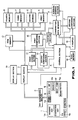
- Fig. 1 is a block diagram showing a data processing apparatus to which the present invention is applied.
- a key input section 1 comprises numeric keys 1a for inputting numeric data, character keys 1b for inputting letters, symbols, and the like, an "IN/OUT” key 1c for designating an input/output mode of the apparatus, and a “function” key 1d for displaying the functions of the apparatus.
- the key input section 1 comprises a "name card” key 1e for setting a name card management mode, a “next item” key 1f for designating an item when data is to be input in the name card management mode, a “registration” key 1g for designating data registration, a “search” key 1h for designating a search for stored data, and “AND” and “OR” keys 1i and 1j for determining search conditions.
- Key input data from the key input section 1 is supplied to a key determining section 2.
- the section 2 supplies the input data from the section 1 to a display buffer 3, and also supplies execution data for designating processing designated by the function key to a control section 4.
- the control section 4 is constituted by a read-only memory (ROM) and stores programs for controlling the respective circuits.
- ROM read-only memory
- control section 4 Upon reception of the execution data operated by the key input section 1 through the key determining section 2, the control section 4 outputs a control command to cause each circuit to perform processing corresponding to a key operation in accordance with a program.
- Input data are respectively stored in first to fourth memories 5 to 8 in units of items in accordance with a control operation of an address control section 9.
- the sets of addresses of the areas, in each of which the items of data relating an individual are stored are stored in a combination data memory 10.
- the contents of the memory 10 are sorted by a sorting section 11.
- An item memory 12 stores the items of data stored in the first to fourth memories 5 to 8.
- First and second search buffers 13 and 14 independently and temporarily hold search data which are input from the key input section 1. These data held in the buffers 13 and 14 are supplied to a first comparing section 15 and compared with the storage contents of the memories 5, 6, 7, and 8. The comparison results from the first comparing section 15 are supplied to the control section 4.
- An X buffer 16 holds one of the address data stored in the combination data memory 10.
- a second comparing section 17 determines whether the address data held in the X buffer 16 coincides with other address data stored in the combination data memory 10, and supplies the determination result to the control section 4.
- a coincidence or noncoincidence flag is set in a flag memory 18 in accordance with the comparison result from the second comparing section 17.
- the display section 19 is constituted by a dot matrix liquid crystal display unit.
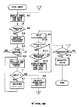
- step A1 the first item name stored in the item memory 12 is read out to the display buffer 3 in response to an instruction from the control section 4.
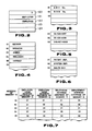
- the item memory 12 will be described in detail below with reference to Fig. 2.
- the item memory 12 has five registers.
- the item memory 12 stores item names and the number thereof necessary for name card management.
- Fig. 2 shows a case wherein an "employer name (name of company)" and an “employe name (name of person)" are respectively stored in registers 121 and 122, and a register 120 stores "2" as the number of items.
- step A1 therefore, the first item name "EMPLOYER" is displayed on the display section 19, and an operator knows that the apparatus is set in a state of waiting for an employer name input (Fig. 13A).
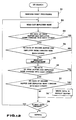
- step A3 a menu of executable functions is displayed on the display section 19. In this case, a menu shown in, e.g., Fig. 13B is displayed. If the operator operates the numeric key 1a to input "3" so as to designate "addition of items” in accordance with the display on the display section 9, this operation is discriminated in step A4, and the flow of control advances to step A5.
- step A5 the number of items stored in the register 120 of the memory 12 is incremented by one.
- Fig. 13C shows the display state of the display section 9 at this time.
- step A6 the input of the item name is detected, and the flow of control advances to step A7.
- step A7 the input data "TELEPHONE" is written in a register 123 of the item name memory 12 as third item name data.
- step A8 When the input operation of the item name is completed, the operator operates the "name card” key 1e (step A8). In response to this key operation, the flow of control returns to step A1, and the apparatus is set in a state of waiting for a data input of the first item "EMPLOYER".
- step A9 When the operator inputs an employer name by using character keys 1b (in step A9) and operates the "next item" key 1f, these key operations are detected in step A10, and the flow of control advances to step A11. In step A11, it is checked whether next item data is present.
- step A12 the next item name "EMPLOYE NAME" is read out and displayed on the display section 19 through the display buffer 3. The flow of control then returns to step A9.
- step A10 When the operator inputs name data and operates the "next item” key 1f, the flow of control advances to steps A10, A11, and A12, and the third item "TELEPHONE” is displayed. If the "registration" key 1g is operated after data corresponding to the item names "TELEPHONE” and “DEPARTMENT” are input in the same manner as described above, NO is obtained in step A10, and YES is obtained in step A13. As a result, the data are registered in step A14. This data registration processing will be described in detail below with reference to Fig. 9.
- step A101 the first data (the employer name) of input data is extracted.
- step A102 it is checked whether data identical with the extracted data has been already stored in the first memory 5. If YES is obtained in step A102, the flow of control advances to step A103 in which the currently input employer name data is not newly registered, and the address of an area of the first memory 5 in which the employer name is stored is written at a predetermined position of the combination data memory 10.
- step A102 If NO is obtained in step A102, the flow of control advances to step A104 to newly store the input employer data in the first memory 5 and to write the address data of an employer name data area of the first memory 5, in a predetermined position of the combination data memory 10.
- step A105 When the registration processing of the employer name data is completed,it is checked in step A105 whether the next input data is present. In this case, since employe name data is present, the flow of control returns to step A101, and processing of the employe name data is executed in the same manner as described above with respect to the second memory 6.
- the respective key input data of a card name are respectively stored in the first to fourth memories 5 to 8 in units of items.
- the first memory 5 stores employer names; the second memory 6, employe names; the third memory 7, telephone numbers; and the fourth memory 8, the names of departments.
- the respective memories 5 to 8 store data so as not to store the same data twice.
- the item data of a given individual is stored in the combination data memory 10 in combination with corresponding address data.
- Figs. 3 to 6 respectively show states of item data stored in the first to fourth memories.
- Fig. 7 shows the contents of the combination data memory 10, wherein data associated with five persons working for two companies are stored.
- the memory 10 stores the respective item data of the individuals as address data of the respective memories in which the data are recorded. That is, each row of the data of a matrix configuration shown in Fig. 7 represents the data of each individual, i.e., each employe.
- the first to fourth columns correspond to the first to fourth memories, respectively. That is, for example, the fifth row data (02, 05, 03, 03) correspond to "BBB Co.” (EMPLOYER), "HAROLD” (EMPLOYE NAME), "045-007-9999" (TELEPHONE), and "SALES DEP.” (DEPARTMENT), respectively.
- search information consists of one or two words. If search information consisting of two words is to be used, an "AND” or “OR” key must be operated between the words to designate a search condition.
- step B6 If the "AND” or “OR” information is input, the flow of control advances to step B6 or B7 depending on a decision made in step B3.
- step B4 If the operator inputs, e.g., "HA" and operates the "search” key 1h, the flow advances to step B4.
- step B4 "HA" input in step B1 is input to the first search buffer 13.
- the first comparing section 15 compares the data stored in the first search buffer 13 with the data stored in the first to fourth memories 5 to 8. In this case, the first two letters of "HAROLD" stored at an address (05) of the second memory 6 coincide with the input "HA".
- the flow of control then advances to step B5, and data of his employer name, his telephone number, and a department to which he belongs are supplied from addresses of other memories which are associated with the address (05) of the second memory 6 to the display buffer 3 to be displayed.
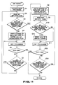
- search data of an employer name and an employe name are input. If, for example, character "B" is input, the "AND” key 1i is operated, characters "HA" are input, and the "search” key 1h is operated, an AND search operation is executed in accordance with the flow chart shown in Fig. 11.
- the input data "B" and "HA” are respectively written in the first and second search buffers 13 and 14. Reset processing is then performed in step C1.
- the address control section 9 resets the addresses of the first to fourth memories (to be 01) and clears the contents of the X buffer 16 and the flag memory 18.
- step C2 The flow of control then advances to step C2 to read out an employer name "ABC Co.” from an address of the first memory 5 corresponding to an employer name address data (01) written at an address (01) of the combination data memory 10.
- step C3 one search data, i.e., the employer name "B” stored in the first search buffer 13 is compared with "ABC Co.” by the first comparing section 15. In this case, since they do not coincide with each other, NO is obtained in step C3, and the flow advances to step C4.
- step C4 the employer name address (01) at which noncoincidence is determined is written in the X buffer 16, and the noncoincidence flag is set in the flag memory 18.
- step C5 the address of the combination data memory 10 is increased by one, and a data end is checked in step C6. In this case, since the remaining data is present, NO is obtained in step C6, and the flow of control advances to step C7.
- the employer name address (01) written at an address (02) of the combination data memory 10 is compared with the address data (01) written in the X buffer 16 by the second comparing section 17 so as to check whether they coincide with each other.
- step C5 the flow of control returns to step C5 to increase the address of the memory 10 by one, and the operation from step C6 is repeated. Subsequently, the operation from step C5 to step C7 is repeated in the same manner as described above.
- Employer name addresses (01) determined to be coincident with the address (01) written in the X buffer 16 in this manner are not regarded as the corresponding data. Note that if a data end is detected and YES is obtained in step C6 in the course of such an operation, the flow returns to the flow chart shown in Fig. 10, and the search operation is completed.
- step C3 If the address of the combination data memory 10 is increased to (04), employer name address data (02) is obtained. Since the address data (02) does not coincide with the address data (01) written in the X buffer 16, NO is obtained by the second comparing section 17 in step C7. As a result, the flow of control returns to step C2. In this case, an employer name "BBB Co.” is read out from an address of the first memory 5 corresponding to the employer name address (02) written at the address (04) of the memory 10. In step C3, the first comparing section 15 compares "BBB Co.” with one search data written in the first search buffer 13, i.e., employer name "B". Since YES is obtained in step C3, the flow advances to step C8.
- step C8 the employer name address (02) at which coincidence is determined is written in the X buffer 16, and at the same time, the coincidence flag is set in the flag memory 18.
- step C9 an employe name "BENJAMIN" is read out from an address of the second memory 6 corresponding to the employe name address (04) written at the address (04) of the memory 10.
- step C10 the readout name is compared with the other search data written in the second search buffer 14, i.e., the employe name "HA". In this case, since NO is obtained in step C10, the flow of control advances to step C11.
- step C11 the address of the combination data memory 10 is increased by one.
- step C12 a data end is checked. If YES is obtained in step C12, the flow of control returns to the processing shown in Fig. 10, thereby completing the search operation. In this case, since NO is obtained in step C12, the flow of control advances to step C13.
- step C13 an employer name address (02) written at an address (05) of the combination data memory 10 is compared with the address data written in the X buffer 16 so as to determine whether they coincide with each other. If an employer name at the corresponding address is different from "BBB Co.” and NO is obtained in step C13, the flow of control returns to the processing shown in Fig. 10, thus completing the search operation.
- step C13 YES is obtained in step C13, and hence the flow of control returns to step C9 to read out a name "HAROLD" from an address of the second memory 16 corresponding to the address (05) of the memory 10.
- step C10 "HAROLD" is compared with the other search data written in the second search buffer 14, i.e., "HA". Since they coincide with each other in this case, the flow of control advances to step C14 to display the search data on the display section 19. That is, in this case, if both the data of the employer name and the employe name coincide with the search data, the corresponding data is determined, and the data to be searched is displayed on the display section 19.
- item data are read out from addresses of the memories 5, 6, 7, and 8 respectively corresponding to the employer name address (02), the employe name address (05), a telephone number address (03), and a department address (03) which are written in the storage area at the address (05) of the combination data memory 10.
- the employer name "BBB Co.”, the employe name "HAROLD”, a telephone number "045-007-9999", and a department "SALES DEP" are displayed on the display section 19 as the data to be searched.
- step D1 An OR search operation is executed in accordance with a flow chart shown in Fig. 12.
- step D1 reset processing is performed.
- the addresses of the combination data memory 10 and the first to fourth memories 5 to 8 are reset (set to be 01) by the address control section 9, and at the same time, the contents of the X buffer 16 and the flag memory 18 are cleared.
- step D2 The flow of control then advances to step D2 to read out an employer name "ABC Co.” from an address of the first memory 5 corresponding to the address (01) written at the address (01) of the memory 10.
- step D3 the readout data and one search data written in the first search buffer 13 are compared with each other by the first comparing section 13. In this case, since they do not coincide with each other, the flow advances to step D4.
- step D4 the employer name "ABC Co.” in the first memory 5 corresponding to the employer address (01) written at the address (01) of the memory 10 is compared with the other search data (the name "HA") written in the second buffer 14. In this case, they do not coincide with each other either, and the flow advances to step D5.
- step D5 an employe name "GEORGE” in the second memory 6 corresponding to an employe name address (01) written at the address (01) of the combination data memory 10 is read out.
- step D6 the first comparing section 15 compares the readout data with one search data written in the first search buffer 13. In this case, since they do not coincide with each other, the flow of control advances to step D7.
- step D7 the employe name "GEORGE” in the second memory 6 corresponding to the employe name address (01) written in the address (01) of the memory 10 is compared with the other search data (the employe name "HA") written in the second search buffer 14. In this case, they do not coincide with each other either, the flow of control advances to step D8.
- step D8 it is checked whether the next data is present. In this case, since the next data is present, the flow of control returns to step D2.
- step D2 the employer name "ABC Co.” stored in a storage area of the first memory 5 corresponding to the employer address (01) written in a storage area of an address (02) of the combination data memory 10 is read out, and the operation from step D3 is executed.
- step D2 the employer name "BBB Co.” in the first memory 5 corresponding to an address (04) of the memory 10 is read out. If the readout employer name is compared with one search data written in the first search buffer 13, they coincide with each other. As a result, the flow of control advances to step D9, and the search data is displayed on the display section 19. In this case, when either the employer name or the employe name of the individual data coincides with the search data, the individual data is determined to be data which has been searched and is displayed on the display section 19.
- item data are read out from addresses of the memories 5, 6, 7, and 8 respectively corresponding to the employer name address (02), the employe name address (04), a telephone number address (03), and a department address (03) which are written in the storage area at the address (04) of the combination data memory 10.
- the employer name "BBB Co.”, the employe name "BENJAMIN”, a telephone number "045-007-9999", and a department "SALES DEP" are displayed on the display section 19 as the data to be searched.
Abstract
Description
- The present invention relates to a data processing apparatus for storing various types of data and displaying stored data as needed.
- Compact electronic recording apparatuses have recently been developed in place of pocketbooks for recording addresses. The apparatus manages data of individual names, telephone numbers, and the like.
- When such a data storage apparatus is set in an input mode, the apparatus is set in a state of waiting for a name data input. When an operator inputs name data to the apparatus, the apparatus sequentially displays a menu designating that each item data such as an address and a telephone number should be input. The operator inputs item data in accordance with the menu. In conventional data storage apparatuses, however, items of input data are limited to predetermined items, e.g., addresses and telephone numbers. For this reason, even if a user demands to manage some special item data, the apparatus cannot satisfy such a demand. Hence, the conventional apparatuses are inconvenient.
- In addition, a data storage apparatus sometimes stores a large number of data representing the same last or first name. In this case, if a data search is to be performed on the basis of, e.g., name data using a conventional apparatus, an operator must read out all the corresponding name data and determine whether each of the readout name data is desired data.
- In the conventional apparatus, therefore, as the number of data registered is increased, data search requires much labor and time. That is, the conventional apparatus is very inconvenient.
- It is an object of the present invention to provide a data processing apparatus which allows an easy search for stored data.
- It is another object of the present invention to provide a data processing apparatus capable of variably setting input data items in accordance with a purpose of a user.
- According to the present invention, there is provided a data processing apparatus comprising:
key input means (1) for inputting data associated with an individual;
item memory means (12) for storing a plurality of item names associated with data to be input;
first data memory means (5 - 8) for storing input data in units of items stored in said item memory means;
second data memory means (10) for storing combinations of the items of data stored in said first memory means (5 - 8) and relating to each individual;
means (1) for inputting a search word;
first comparing means (15) for comparing the input search word with the data stored in said first memory means; and
output means (4, 3, 19) for reading out each item data of an individual from said first memory means on the basis of a combination stored in said second memory means, which combination is associated with data whose coincide is detected in said first comparing means. - A data processing apparatus comprises:
key input means (1) having character keys for a data input;
first memory means (12) for storing item names of input data;
second memory means (5 - 8) for storing the input data in units of items;
guidance means (3, 4, 19) for sequentially displaying the item names stored in said first memory means and guiding a data input sequence of the items;
data write means (4, 9) for writing the data, which is input in accordance with the guidance by said guidance means, in said second memory means in units of items;
adding means (4) for adding an item name to the item names already stored in said first memory means; and
control means (4, 9) for, when said input guidance means displays an item added by said adding means and data is input in accordance with the item, designating a predetermined area of said said second memory means, which is different from an area in which item data has been stored, and causing said data write means to write data in the predetermined area. - This invention can be more fully understood from the following detailed description when taken in conjunction with the accompanying drawings, in which:
- Fig. 1 is a block diagram showing a data processing apparatus to which the present invention is applied;
- Fig. 2 is a view showing an arrangement of an item memory of the data processing apparatus;
- Figs. 3 to 6 are views respectively showing the contents of first to fourth memories;
- Fig. 7 is a view showing an arrangement of a combination data memory;
- Fig. 8 is a flow chart showing an operation of data input;
- Fig. 9 is a flow chart showing an operation of data registration;
- Fig. 10 is a flow chart showing a data search operation;
- Fig. 11 is a flow chart for explaining an AND search operation of data search operations in detail;
- Fig. 12 is a flow chart for explaining an OR search operation of data search operations in detail; and
- Figs. 13A to 13D are views respectively showing key operations and displays when data items to be handled by the data processing apparatus are to be added.
- Fig. 1 is a block diagram showing a data processing apparatus to which the present invention is applied.
- A
key input section 1 comprisesnumeric keys 1a for inputting numeric data,character keys 1b for inputting letters, symbols, and the like, an "IN/OUT"key 1c for designating an input/output mode of the apparatus, and a "function"key 1d for displaying the functions of the apparatus. In addition, thekey input section 1 comprises a "name card"key 1e for setting a name card management mode, a "next item"key 1f for designating an item when data is to be input in the name card management mode, a "registration" key 1g for designating data registration, a "search"key 1h for designating a search for stored data, and "AND" and "OR"keys - Key input data from the
key input section 1 is supplied to akey determining section 2. Thesection 2 supplies the input data from thesection 1 to adisplay buffer 3, and also supplies execution data for designating processing designated by the function key to acontrol section 4. - The
control section 4 is constituted by a read-only memory (ROM) and stores programs for controlling the respective circuits. - Upon reception of the execution data operated by the
key input section 1 through thekey determining section 2, thecontrol section 4 outputs a control command to cause each circuit to perform processing corresponding to a key operation in accordance with a program. - Input data are respectively stored in first to
fourth memories 5 to 8 in units of items in accordance with a control operation of anaddress control section 9. The sets of addresses of the areas, in each of which the items of data relating an individual are stored are stored in acombination data memory 10. The contents of thememory 10 are sorted by asorting section 11. Anitem memory 12 stores the items of data stored in the first tofourth memories 5 to 8. - First and
second search buffers key input section 1. These data held in thebuffers first comparing section 15 and compared with the storage contents of thememories first comparing section 15 are supplied to thecontrol section 4. - An
X buffer 16 holds one of the address data stored in thecombination data memory 10. Asecond comparing section 17 determines whether the address data held in theX buffer 16 coincides with other address data stored in thecombination data memory 10, and supplies the determination result to thecontrol section 4. - A coincidence or noncoincidence flag is set in a
flag memory 18 in accordance with the comparison result from thesecond comparing section 17. - Note that the key input data, the storage data of the
item memory 12, and the data stored in the first to fourth memories are held in thedisplay buffer 3, and are displayed on adisplay section 19. Thedisplay section 19 is constituted by a dot matrix liquid crystal display unit. - An operation of the embodiment having the above-described arrangement will be described below.
- Data input to the apparatus will be described first.
- An operator operates the "IN/OUT"
key 1c of thekey input section 1 to set the apparatus in the input mode. The operator then operates the "name card" key 1e to cause the apparatus to start execution of processing for storing name card data, as shown in Fig. 8. This storage processing will be described below with reference to Fig. 8. - In step A1, the first item name stored in the
item memory 12 is read out to thedisplay buffer 3 in response to an instruction from thecontrol section 4. - The
item memory 12 will be described in detail below with reference to Fig. 2. Theitem memory 12 has five registers. Theitem memory 12 stores item names and the number thereof necessary for name card management. Fig. 2 shows a case wherein an "employer name (name of company)" and an "employe name (name of person)" are respectively stored inregisters register 120 stores "2" as the number of items. - In step A1, therefore, the first item name "EMPLOYER" is displayed on the
display section 19, and an operator knows that the apparatus is set in a state of waiting for an employer name input (Fig. 13A). - In this state, the operator can add an item name of data to be stores. When an item name is to be added, the operator operates the "function" key 1d. When the operation of the "function" key 1d is detected in step A2, the flow of control advances to step A3. In step A3, a menu of executable functions is displayed on the
display section 19. In this case, a menu shown in, e.g., Fig. 13B is displayed. If the operator operates the numeric key 1a to input "3" so as to designate "addition of items" in accordance with the display on thedisplay section 9, this operation is discriminated in step A4, and the flow of control advances to step A5. - In step A5, the number of items stored in the
register 120 of thememory 12 is incremented by one. - In Fig. 2, since the number of items is "2", the updated number of items becomes "3". In this state, the apparatus is then set in a state of waiting for a data input. Fig. 13C shows the display state of the
display section 9 at this time. - Subsequently, the operator inputs an item name to be added in accordance with the display on the
display section 9. If a "telephone number" is to be added as an item name, the operator inputs "TELEPHONE" with the "character"keys 1c of thekey input section 1 and operates the "registration" key 1g. Fig. 13D shows the display state of thedisplay section 9 at this time. In step A6, the input of the item name is detected, and the flow of control advances to step A7. In step A7, the input data "TELEPHONE" is written in aregister 123 of theitem name memory 12 as third item name data. - If the operator registers, e.g., "DEPARTMENT" as a fourth item name in the same manner as described above, "DEPARTMENT" is stored in a
register 124 of theitem memory 12. - When the input operation of the item name is completed, the operator operates the "name card" key 1e (step A8). In response to this key operation, the flow of control returns to step A1, and the apparatus is set in a state of waiting for a data input of the first item "EMPLOYER".
- When the operator inputs an employer name by using
character keys 1b (in step A9) and operates the "next item" key 1f, these key operations are detected in step A10, and the flow of control advances to step A11. In step A11, it is checked whether next item data is present. - In this case, since "EMPLOYE NAME" is present as the next item name, the flow of control advances to step A12. In step A12, the next item name "EMPLOYE NAME" is read out and displayed on the
display section 19 through thedisplay buffer 3. The flow of control then returns to step A9. - When the operator inputs name data and operates the "next item" key 1f, the flow of control advances to steps A10, A11, and A12, and the third item "TELEPHONE" is displayed. If the "registration" key 1g is operated after data corresponding to the item names "TELEPHONE" and "DEPARTMENT" are input in the same manner as described above, NO is obtained in step A10, and YES is obtained in step A13. As a result, the data are registered in step A14. This data registration processing will be described in detail below with reference to Fig. 9.
- In step A101, the first data (the employer name) of input data is extracted. In step A102, it is checked whether data identical with the extracted data has been already stored in the
first memory 5. If YES is obtained in step A102, the flow of control advances to step A103 in which the currently input employer name data is not newly registered, and the address of an area of thefirst memory 5 in which the employer name is stored is written at a predetermined position of thecombination data memory 10. - If NO is obtained in step A102, the flow of control advances to step A104 to newly store the input employer data in the
first memory 5 and to write the address data of an employer name data area of thefirst memory 5, in a predetermined position of thecombination data memory 10. - When the registration processing of the employer name data is completed,it is checked in step A105 whether the next input data is present. In this case, since employe name data is present, the flow of control returns to step A101, and processing of the employe name data is executed in the same manner as described above with respect to the
second memory 6. - In this manner, the respective key input data of a card name are respectively stored in the first to
fourth memories 5 to 8 in units of items. Thefirst memory 5 stores employer names; thesecond memory 6, employe names; thethird memory 7, telephone numbers; and thefourth memory 8, the names of departments. In this case, therespective memories 5 to 8 store data so as not to store the same data twice. The item data of a given individual is stored in thecombination data memory 10 in combination with corresponding address data. - Figs. 3 to 6 respectively show states of item data stored in the first to fourth memories. Fig. 7 shows the contents of the
combination data memory 10, wherein data associated with five persons working for two companies are stored. - An arrangement of the
combination data memory 10 shown in Fig. 7 should be noted. Thememory 10 stores the respective item data of the individuals as address data of the respective memories in which the data are recorded. That is, each row of the data of a matrix configuration shown in Fig. 7 represents the data of each individual, i.e., each employe. The first to fourth columns correspond to the first to fourth memories, respectively. That is, for example, the fifth row data (02, 05, 03, 03) correspond to "BBB Co." (EMPLOYER), "HAROLD" (EMPLOYE NAME), "045-007-9999" (TELEPHONE), and "SALES DEP." (DEPARTMENT), respectively. - A search for stored data will be described below with reference to Fig. 10.
- When a data search is to be performed, the apparatus is set in an output mode. An operator inputs search information by using the
character keys 1b or thenumeric keys 1a of thekey input section 1, and operates the "search" key 1h. In response to this key operation, a search operation is started (steps B1 and B2). For example, search information consists of one or two words. If search information consisting of two words is to be used, an "AND" or "OR" key must be operated between the words to designate a search condition. - If the "AND" or "OR" information is input, the flow of control advances to step B6 or B7 depending on a decision made in step B3.
- If the operator inputs, e.g., "HA" and operates the "search" key 1h, the flow advances to step B4.
- In step B4, "HA" input in step B1 is input to the
first search buffer 13. The first comparingsection 15 compares the data stored in thefirst search buffer 13 with the data stored in the first tofourth memories 5 to 8. In this case, the first two letters of "HAROLD" stored at an address (05) of thesecond memory 6 coincide with the input "HA". The flow of control then advances to step B5, and data of his employer name, his telephone number, and a department to which he belongs are supplied from addresses of other memories which are associated with the address (05) of thesecond memory 6 to thedisplay buffer 3 to be displayed. - A search operation using two words will be described below. In this embodiment, search data of an employer name and an employe name are input. If, for example, character "B" is input, the "AND" key 1i is operated, characters "HA" are input, and the "search" key 1h is operated, an AND search operation is executed in accordance with the flow chart shown in Fig. 11.
- The input data "B" and "HA" are respectively written in the first and second search buffers 13 and 14. Reset processing is then performed in step C1. In this case, the
address control section 9 resets the addresses of the first to fourth memories (to be 01) and clears the contents of theX buffer 16 and theflag memory 18. - The flow of control then advances to step C2 to read out an employer name "ABC Co." from an address of the
first memory 5 corresponding to an employer name address data (01) written at an address (01) of thecombination data memory 10. In step C3, one search data, i.e., the employer name "B" stored in thefirst search buffer 13 is compared with "ABC Co." by the first comparingsection 15. In this case, since they do not coincide with each other, NO is obtained in step C3, and the flow advances to step C4. - In step C4, the employer name address (01) at which noncoincidence is determined is written in the
X buffer 16, and the noncoincidence flag is set in theflag memory 18. In step C5, the address of thecombination data memory 10 is increased by one, and a data end is checked in step C6. In this case, since the remaining data is present, NO is obtained in step C6, and the flow of control advances to step C7. The employer name address (01) written at an address (02) of thecombination data memory 10 is compared with the address data (01) written in theX buffer 16 by the second comparingsection 17 so as to check whether they coincide with each other. In this case, since they coincide with each other, the flow of control returns to step C5 to increase the address of thememory 10 by one, and the operation from step C6 is repeated. Subsequently, the operation from step C5 to step C7 is repeated in the same manner as described above. Employer name addresses (01) determined to be coincident with the address (01) written in theX buffer 16 in this manner are not regarded as the corresponding data. Note that if a data end is detected and YES is obtained in step C6 in the course of such an operation, the flow returns to the flow chart shown in Fig. 10, and the search operation is completed. - If the address of the
combination data memory 10 is increased to (04), employer name address data (02) is obtained. Since the address data (02) does not coincide with the address data (01) written in theX buffer 16, NO is obtained by the second comparingsection 17 in step C7. As a result, the flow of control returns to step C2. In this case, an employer name "BBB Co." is read out from an address of thefirst memory 5 corresponding to the employer name address (02) written at the address (04) of thememory 10. In step C3, the first comparingsection 15 compares "BBB Co." with one search data written in thefirst search buffer 13, i.e., employer name "B". Since YES is obtained in step C3, the flow advances to step C8. - In step C8, the employer name address (02) at which coincidence is determined is written in the
X buffer 16, and at the same time, the coincidence flag is set in theflag memory 18. In step C9, an employe name "BENJAMIN" is read out from an address of thesecond memory 6 corresponding to the employe name address (04) written at the address (04) of thememory 10. In step C10, the readout name is compared with the other search data written in thesecond search buffer 14, i.e., the employe name "HA". In this case, since NO is obtained in step C10, the flow of control advances to step C11. - In step C11, the address of the
combination data memory 10 is increased by one. In step C12, a data end is checked. If YES is obtained in step C12, the flow of control returns to the processing shown in Fig. 10, thereby completing the search operation. In this case, since NO is obtained in step C12, the flow of control advances to step C13. In step C13, an employer name address (02) written at an address (05) of thecombination data memory 10 is compared with the address data written in theX buffer 16 so as to determine whether they coincide with each other. If an employer name at the corresponding address is different from "BBB Co." and NO is obtained in step C13, the flow of control returns to the processing shown in Fig. 10, thus completing the search operation. In this case, however, YES is obtained in step C13, and hence the flow of control returns to step C9 to read out a name "HAROLD" from an address of thesecond memory 16 corresponding to the address (05) of thememory 10. In step C10, "HAROLD" is compared with the other search data written in thesecond search buffer 14, i.e., "HA". Since they coincide with each other in this case, the flow of control advances to step C14 to display the search data on thedisplay section 19. That is, in this case, if both the data of the employer name and the employe name coincide with the search data, the corresponding data is determined, and the data to be searched is displayed on thedisplay section 19. In this case, item data are read out from addresses of thememories combination data memory 10. As a result, the employer name "BBB Co.", the employe name "HAROLD", a telephone number "045-007-9999", and a department "SALES DEP" are displayed on thedisplay section 19 as the data to be searched. - An OR search operation is executed in accordance with a flow chart shown in Fig. 12. In step D1, reset processing is performed. The addresses of the
combination data memory 10 and the first tofourth memories 5 to 8 are reset (set to be 01) by theaddress control section 9, and at the same time, the contents of theX buffer 16 and theflag memory 18 are cleared. - The flow of control then advances to step D2 to read out an employer name "ABC Co." from an address of the
first memory 5 corresponding to the address (01) written at the address (01) of thememory 10. In step D3, the readout data and one search data written in thefirst search buffer 13 are compared with each other by the first comparingsection 13. In this case, since they do not coincide with each other, the flow advances to step D4. In step D4, the employer name "ABC Co." in thefirst memory 5 corresponding to the employer address (01) written at the address (01) of thememory 10 is compared with the other search data (the name "HA") written in thesecond buffer 14. In this case, they do not coincide with each other either, and the flow advances to step D5. - In step D5, an employe name "GEORGE" in the
second memory 6 corresponding to an employe name address (01) written at the address (01) of thecombination data memory 10 is read out. In step D6, the first comparingsection 15 compares the readout data with one search data written in thefirst search buffer 13. In this case, since they do not coincide with each other, the flow of control advances to step D7. In step D7, the employe name "GEORGE" in thesecond memory 6 corresponding to the employe name address (01) written in the address (01) of thememory 10 is compared with the other search data (the employe name "HA") written in thesecond search buffer 14. In this case, they do not coincide with each other either, the flow of control advances to step D8. In step D8, it is checked whether the next data is present. In this case, since the next data is present, the flow of control returns to step D2. In step D2, the employer name "ABC Co." stored in a storage area of thefirst memory 5 corresponding to the employer address (01) written in a storage area of an address (02) of thecombination data memory 10 is read out, and the operation from step D3 is executed. - Subsequently, an operation similar to the above-described operation is repeated while the address of the
combination data memory 10 is sequentially updated. In step D2, the employer name "BBB Co." in thefirst memory 5 corresponding to an address (04) of thememory 10 is read out. If the readout employer name is compared with one search data written in thefirst search buffer 13, they coincide with each other. As a result, the flow of control advances to step D9, and the search data is displayed on thedisplay section 19. In this case, when either the employer name or the employe name of the individual data coincides with the search data, the individual data is determined to be data which has been searched and is displayed on thedisplay section 19. In this case, item data are read out from addresses of thememories combination data memory 10. As a result, the employer name "BBB Co.", the employe name "BENJAMIN", a telephone number "045-007-9999", and a department "SALES DEP" are displayed on thedisplay section 19 as the data to be searched.
Claims (17)
item memory means (12) for storing a plurality of item names associated with data to be input;
first data memory means (5 - 8) for storing input data in units of items stored in said item memory means;
second data memory means (10) for storing combinations of the items of data stored in said first memory means (5 - 8) and relating to each individual;
means (1) for inputting a search word;
first comparing means (15) for comparing the input search word with the data stored in said first memory means; and
output means (4, 3, 19) for reading out each item data of an individual from said first memory means on the basis of a combination stored in said second memory means, which combination is associated with data whose coincide is detected in said first comparing means.
said first comparing means (15) comprises means for comparing the data stored in said first data memory means with the search word one by one in units of items, and
said output means comprises means for extracting, from a data combination stored in said second memory means in association with one data, data associated with items other than an item to which the one data determined to coincide with the search word by said first comparing means belongs.
said output means (3, 4, 19) comprises means for selecting, from said second memory means, combination data of an individual, the combination data including two address data of areas storing two data founded to coincide with the first and second search words by said first comparing means, whereby
said output means reads out item data of the individual selected by said selecting means from said first memory means and outputs the readout item data.
memory means (16) for storing address data of a storage area of said first data memory means, the storage area storing item data which is determined to be noncoincident with the first search word by said first comparing means;
second comparing means (17) for comparing the address data stored in said memory means with next address data which is in said second memory means and belongs to an item corresponding to the address data stored in said memory means;
means (4) for further designating next address data belonging to the item when a comparison result from said second comparing means represents a noncoincidence; and
control means (4) for, when a comparison result from said comparing means represents noncoincidence, causing said first comparing means to compare item data held in a storage area of said first data memory means corresponding to an address at which the noncoincidence is determined with the first search word.
said output means (3, 4, 19) comprises means for selecting combination data of an individual which includes address data of a storage area holding item data with which at least one of the two search words coincides.
said second memory means (10) comprises means for storing item data of each individual as combinations of address data of said submemory means.
key input means (1) having character keys for a data input;
first memory means (12) for storing item names of input data;
second memory means (5 - 8) for storing the input data in units of items;
guidance means (3, 4, 19) for sequentially displaying the item names stored in said first memory means and guiding a data input sequence of the items;
data write means (4, 9) for writing the data, which is input in accordance with the guidance by said guidance means, in said second memory means in units of items;
adding means (4) for adding an item name to the item names already stored in said first memory means; and
control means (4, 9) for, when said input guidance means displays an item added by said adding means and data is input in accordance with the item, designating a predetermined area of said second memory means, which is different from an area in which item data has been stored, and causing said data write means to write data in the predetermined area.
comparing means (15) for comparing input data with data which has been stored in said second memory means;
means (14) for inhibiting registration of the input data in said second memory means when said comparing means detects data coinciding with the input data in said second memory means; and
control means (4, 9) for causing said third memory means (10) to store the data founded to coincide with the input data in said second memory means as data constructing the combination upon operation of said inhibiting means.
Applications Claiming Priority (4)
| Application Number | Priority Date | Filing Date | Title |
|---|---|---|---|
| JP9553088U JPH0218165U (en) | 1988-07-19 | 1988-07-19 | |
| JP1988095531U JPH0624913Y2 (en) | 1988-07-19 | 1988-07-19 | Information storage device |
| JP95531/88U | 1988-07-19 | ||
| JP95530/88U | 1988-07-19 |
Publications (3)
| Publication Number | Publication Date |
|---|---|
| EP0351786A2 true EP0351786A2 (en) | 1990-01-24 |
| EP0351786A3 EP0351786A3 (en) | 1991-06-26 |
| EP0351786B1 EP0351786B1 (en) | 1997-05-02 |
Family
ID=26436751
Family Applications (1)
| Application Number | Title | Priority Date | Filing Date |
|---|---|---|---|
| EP89113164A Expired - Lifetime EP0351786B1 (en) | 1988-07-19 | 1989-07-18 | Data processing apparatus |
Country Status (3)
| Country | Link |
|---|---|
| EP (1) | EP0351786B1 (en) |
| DE (1) | DE68928011T2 (en) |
| HK (1) | HK1002815A1 (en) |
Cited By (2)
| Publication number | Priority date | Publication date | Assignee | Title |
|---|---|---|---|---|
| EP0410452A2 (en) * | 1989-07-28 | 1991-01-30 | Casio Computer Company Limited | Data totaling apparatus |
| EP0927940A1 (en) * | 1997-12-31 | 1999-07-07 | The Explorid Group B.V. | Database and method for building a database |
Citations (3)
| Publication number | Priority date | Publication date | Assignee | Title |
|---|---|---|---|---|
| EP0079465A2 (en) * | 1981-11-13 | 1983-05-25 | International Business Machines Corporation | Method for storing and accessing a relational data base |
| EP0253138A2 (en) * | 1986-06-17 | 1988-01-20 | Sharp Kabushiki Kaisha | Data processing device |
| US4791561A (en) * | 1987-04-17 | 1988-12-13 | Wang Laboratories, Inc. | Interactive construction of means for database maintenance |
-
1989
- 1989-07-18 EP EP89113164A patent/EP0351786B1/en not_active Expired - Lifetime
- 1989-07-18 DE DE68928011T patent/DE68928011T2/en not_active Expired - Fee Related
-
1998
- 1998-02-23 HK HK98101380A patent/HK1002815A1/en not_active IP Right Cessation
Patent Citations (3)
| Publication number | Priority date | Publication date | Assignee | Title |
|---|---|---|---|---|
| EP0079465A2 (en) * | 1981-11-13 | 1983-05-25 | International Business Machines Corporation | Method for storing and accessing a relational data base |
| EP0253138A2 (en) * | 1986-06-17 | 1988-01-20 | Sharp Kabushiki Kaisha | Data processing device |
| US4791561A (en) * | 1987-04-17 | 1988-12-13 | Wang Laboratories, Inc. | Interactive construction of means for database maintenance |
Non-Patent Citations (1)
| Title |
|---|
| D.F. Stubbs and N.W. Webre: "Data Structures with Abstract Data Types and Pascal" 1985, Brooks/Cole Publishing Company, Monterey, California * |
Cited By (3)
| Publication number | Priority date | Publication date | Assignee | Title |
|---|---|---|---|---|
| EP0410452A2 (en) * | 1989-07-28 | 1991-01-30 | Casio Computer Company Limited | Data totaling apparatus |
| EP0410452A3 (en) * | 1989-07-28 | 1991-06-26 | Casio Computer Company Limited | Data totaling apparatus |
| EP0927940A1 (en) * | 1997-12-31 | 1999-07-07 | The Explorid Group B.V. | Database and method for building a database |
Also Published As
| Publication number | Publication date |
|---|---|
| EP0351786A3 (en) | 1991-06-26 |
| DE68928011T2 (en) | 1997-08-14 |
| HK1002815A1 (en) | 1998-09-18 |
| DE68928011D1 (en) | 1997-06-05 |
| EP0351786B1 (en) | 1997-05-02 |
Similar Documents
| Publication | Publication Date | Title |
|---|---|---|
| US5363504A (en) | Electronic filing method and apparatus | |
| JP2689259B2 (en) | Menu processing device | |
| US7322012B2 (en) | Display program, display method and display device | |
| EP0649108B1 (en) | Data storage apparatus | |
| US4835735A (en) | Card image data processing system | |
| EP0351786A2 (en) | Data processing apparatus | |
| JPH07307826A (en) | Electronic equipment | |
| JPH08329156A (en) | Organization chart processor | |
| JPH0233661A (en) | Character processor containing automatic address input function | |
| EP0453840A2 (en) | Data display apparatus | |
| JPH01290016A (en) | Data input system | |
| JPH0514304B2 (en) | ||
| JPH0827788B2 (en) | Information management device | |
| JP2998393B2 (en) | Data input device | |
| JP2585048Y2 (en) | Numeric character input device | |
| JPH0237466A (en) | Information processing system | |
| JPH0132544B2 (en) | ||
| JPS58151636A (en) | Address information input device | |
| JPH05173893A (en) | Data storage device | |
| JPS62115536A (en) | Information management equipment | |
| JP3067083B2 (en) | Document input device | |
| JPH064486A (en) | Data storage device | |
| JPH11345152A (en) | Data processor and storage medium thereof | |
| JPH0490089A (en) | Management device using card | |
| JPS60129878A (en) | Character input system |
Legal Events
| Date | Code | Title | Description |
|---|---|---|---|
| PUAI | Public reference made under article 153(3) epc to a published international application that has entered the european phase |
Free format text: ORIGINAL CODE: 0009012 |
|
| AK | Designated contracting states |
Kind code of ref document: A2 Designated state(s): DE FR GB |
|
| PUAL | Search report despatched |
Free format text: ORIGINAL CODE: 0009013 |
|
| 17P | Request for examination filed |
Effective date: 19910322 |
|
| AK | Designated contracting states |
Kind code of ref document: A3 Designated state(s): DE FR GB |
|
| 17Q | First examination report despatched |
Effective date: 19931230 |
|
| GRAG | Despatch of communication of intention to grant |
Free format text: ORIGINAL CODE: EPIDOS AGRA |
|
| GRAH | Despatch of communication of intention to grant a patent |
Free format text: ORIGINAL CODE: EPIDOS IGRA |
|
| GRAH | Despatch of communication of intention to grant a patent |
Free format text: ORIGINAL CODE: EPIDOS IGRA |
|
| GRAA | (expected) grant |
Free format text: ORIGINAL CODE: 0009210 |
|
| AK | Designated contracting states |
Kind code of ref document: B1 Designated state(s): DE FR GB |
|
| REF | Corresponds to: |
Ref document number: 68928011 Country of ref document: DE Date of ref document: 19970605 |
|
| ET | Fr: translation filed | ||
| PLBE | No opposition filed within time limit |
Free format text: ORIGINAL CODE: 0009261 |
|
| STAA | Information on the status of an ep patent application or granted ep patent |
Free format text: STATUS: NO OPPOSITION FILED WITHIN TIME LIMIT |
|
| 26N | No opposition filed | ||
| PGFP | Annual fee paid to national office [announced via postgrant information from national office to epo] |
Ref country code: FR Payment date: 20000711 Year of fee payment: 12 |
|
| PGFP | Annual fee paid to national office [announced via postgrant information from national office to epo] |
Ref country code: GB Payment date: 20000713 Year of fee payment: 12 |
|
| PGFP | Annual fee paid to national office [announced via postgrant information from national office to epo] |
Ref country code: DE Payment date: 20000717 Year of fee payment: 12 |
|
| PG25 | Lapsed in a contracting state [announced via postgrant information from national office to epo] |
Ref country code: GB Free format text: LAPSE BECAUSE OF NON-PAYMENT OF DUE FEES Effective date: 20010718 |
|
| GBPC | Gb: european patent ceased through non-payment of renewal fee |
Effective date: 20010718 |
|
| PG25 | Lapsed in a contracting state [announced via postgrant information from national office to epo] |
Ref country code: FR Free format text: LAPSE BECAUSE OF NON-PAYMENT OF DUE FEES Effective date: 20020329 |
|
| PG25 | Lapsed in a contracting state [announced via postgrant information from national office to epo] |
Ref country code: DE Free format text: LAPSE BECAUSE OF NON-PAYMENT OF DUE FEES Effective date: 20020501 |
|
| REG | Reference to a national code |
Ref country code: FR Ref legal event code: ST |