EP0351540A2 - Arthroskopie-Hakenstanze - Google Patents
Arthroskopie-Hakenstanze Download PDFInfo
- Publication number
- EP0351540A2 EP0351540A2 EP89110440A EP89110440A EP0351540A2 EP 0351540 A2 EP0351540 A2 EP 0351540A2 EP 89110440 A EP89110440 A EP 89110440A EP 89110440 A EP89110440 A EP 89110440A EP 0351540 A2 EP0351540 A2 EP 0351540A2
- Authority
- EP
- European Patent Office
- Prior art keywords
- section
- movable
- outer shaft
- hook
- cross
- Prior art date
- Legal status (The legal status is an assumption and is not a legal conclusion. Google has not performed a legal analysis and makes no representation as to the accuracy of the status listed.)
- Granted
Links
Images

Classifications
-
- A—HUMAN NECESSITIES
- A61—MEDICAL OR VETERINARY SCIENCE; HYGIENE
- A61B—DIAGNOSIS; SURGERY; IDENTIFICATION
- A61B17/00—Surgical instruments, devices or methods, e.g. tourniquets
- A61B17/16—Bone cutting, breaking or removal means other than saws, e.g. Osteoclasts; Drills or chisels for bones; Trepans
- A61B17/1604—Chisels; Rongeurs; Punches; Stamps
- A61B17/1606—Chisels; Rongeurs; Punches; Stamps of forceps type, i.e. having two jaw elements moving relative to each other
- A61B17/1608—Chisels; Rongeurs; Punches; Stamps of forceps type, i.e. having two jaw elements moving relative to each other the two jaw elements being linked to two elongated shaft elements moving longitudinally relative to each other
-
- A—HUMAN NECESSITIES
- A61—MEDICAL OR VETERINARY SCIENCE; HYGIENE
- A61B—DIAGNOSIS; SURGERY; IDENTIFICATION
- A61B17/00—Surgical instruments, devices or methods, e.g. tourniquets
- A61B17/32—Surgical cutting instruments
-
- A—HUMAN NECESSITIES
- A61—MEDICAL OR VETERINARY SCIENCE; HYGIENE
- A61B—DIAGNOSIS; SURGERY; IDENTIFICATION
- A61B2217/00—General characteristics of surgical instruments
- A61B2217/002—Auxiliary appliance
- A61B2217/005—Auxiliary appliance with suction drainage system
Definitions
- the invention relates to an arthroscopic hook punch according to DE-OS 35 26 822, which consists of a fixed stamped part formed from the distal end of a round outer shaft and a movable hook jaw part which can be pivoted by means of a push rod which is axially movable by a scissor handle runs through the outer shaft in addition to a parallel flushing or suction channel.
- the known hook punches according to the aforementioned type have the disadvantage that the push rod comes into direct contact with the tissue or bone parts to be suctioned off or with the soiled rinsing or suction liquid, so that the spreading of germs and obstruction of the suctioning is possible with the known consequences .
- the object of the invention is to avoid carry-over of germs, to ensure unhindered suction and to keep the diameter of the outer shaft as small as possible, but to design the push rod in this way, that the movable punch jaw part can be actuated by a handle with high power transmission by means of the push rod.
- a supplementary task is that the cartilage or bone parts removed by the hook punch can be discharged through the suction channel unhindered even when the mouth is closed.
- the arthroscopic hook punch consists of an attachment 2 to be coupled with a scissor handle 1 of the type that the attachment 2 can be connected to known scissor handles already available in a clinic or practice. Different, different hook punches can therefore be used can be used for existing scissor handles.
- the different sizes of attachments 2 each consist of an outer shaft 3, the distal shaft end of which forms the fixed jaw part 4.
- the shaft 3 is provided proximally with a coupling part 5 of a known type, with which the fixed handle leg 1 a can be exchangeably connected by the coupling part 6.
- a flushing or suction channel 7 runs through the shaft 3 and is provided with an angled connecting piece 8 located distally in front of the handle leg 10 for the connection of a negative pressure.
- This channel 7 has a substantially circular cross section, which is provided at the top with a flat 7a.
- This flattening 7a and the upper inner part of the shaft 3 form the tightest possible, sealing guide for the correspondingly profiled push rod 9, which allows the transfer of large forces from the movable handle leg 10 to the movable hook jaw part 11 due to its cross section, this embodiment having a small diameter of the outer shaft 3 leads to a relatively wide suction channel 7.
- the jaw part 11 is provided with a lower, relatively deep recess 12, which is able to receive all punched tissue or bone parts.
- the suction channel 7 directly adjoins this recess 13 when the punching mouth is closed.
- the distal end of the push rod and the proximal end interlock in the area of their articulated connection, so that the suction of the rinsing liquid in this area is effectively prevented.
Abstract
Description
- Die Erfindung geht aus von einer Arthroskopie-Hakenstanze nach der DE-OS 35 26 822, die aus einem aus dem distalen Ende eines runden Außenschaftes gebildeten feststehenden Stanzteil und einem beweglichen Hakenmaulteil besteht, das mittels einer durch einen Scherengriff axial bewegbaren Schubstange verschwenkbar ist, die neben einem parallelen Spül- bzw. Absaugkanal durch den Außenschaft verläuft.
- Die bekannten Hakenstanzen nach der vorerwähnten Art weisen den Nachteil auf, daß die Schubstange unmittelbar mit den abzusaugenden Gewebe- oder Knochenteilen oder der verschmutzten Spül- oder Absaugflüssigkeit in Berührung kommt, so daß dadurch eine Keimverschleppung sowie eine Behinderung der Absaugung mit den bekannten Folgen möglich ist.
- Die Aufgabe der Erfindung besteht darin, Keimverschleppungen zu vermeiden,eine ungehinderte Absaugung zu gewährleisten und hierbei den Durchmesser des Außenschaftes so klein wie möglich zu halten, aber dabei die Schubstange so auszubilden, daß das bewegliche Stanzmaulteil durch eine Handhabe bei hoher Kraftübertragung mittels der Schubstange betätigt werden kann.
- Eine ergänzende Aufgabe besteht darin, daß die durch die Hakenstanze abgetragenen Knorpel- oder Knochenteile auch bei geschlossenem Maul durch den Absaugkanal ungehindert abgeführt werden können.
- Weiter ist vorgesehen, für das Instrument in der Klinik oder in der Praxis vorhandene Scherengriffe verwenden zu können.
- Die Aufgabe der Erfindung wird durch den Patentanspruch 1 gelöst.
- Weiter wird diese Lösung durch die Merkmale des Anspruches 2 ergänzt.
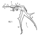
- Die Erfindung ist nachstehend anhand der Zeichnung beschrieben. Es zeigen:
- Figur 1 eine Gesamtansicht der Arthroskopie-Hakenstanze,
- Figur 2 den Aufsatz der Stanze ohne Handgriff,
- Figur 3
- und 4 zwei Querschnitte nach den Linien III-III und IV bis IV der Figur 2.
- Die Arthroskopie-Hakenstanze besteht aus einem mit einem Scherengriff 1 zu kuppelnden Aufsatz 2 der Art, daß der Aufsatz 2 mit in einer Klinik oder einem Praxis bereits vorhandenen,bekannten Scherengriff verbindbar ist. Es können daher verschiedene, unterschiedliche Hakenstanzen für vorhandene Scherengriffe verwendet werden.
- Die in den Größenabmessungen unterschiedlichen Aufsätze 2 bestehen jeweils aus einem Außenschaft 3, dessen distales Schaftende das feststehende Maulteil 4 bildet. Der Schaft 3 ist proximal mit einem Kupplungsteil 5 bekannter Art versehen, mit dem der feststehende Griffschenkel 1a durch den Kupplungsteil 6 austauschbar verbindbar ist.
- Durch den Schaft 3 verläuft ein Spül- bzw. Absaugkanal 7, der mit einem abgewinkelten, distal vor dem Griffschenkel 10 liegenden Anschlußstutzen 8 für den Anschluß eines Unterdrucks versehen ist. Dieser Kanal 7 besitzt im wesentlichen Kreisquerschnitt, der oben mit einer Abflachung 7a versehen ist.
- Diese Abflachung 7a und der obere Innenteil des Schaftes 3 bilden eine möglichst enge, abdichtende Führung für die entsprechend profilierte Schubstange 9, die durch ihren Querschnitt die Übertragung großer Kräfte vom beweglichen Handgriffschenkel 10 auf das bewegliche Hakenmaulteil 11 zuläßt, wobei diese Ausführung zu einem geringen Durchmesser des Außenschaftes 3 bei verhältnismäßig weitem Absaugkanal 7 führt. Das Maulteil 11 ist mit einer unteren,verhältnismäßig tiefen Ausnehmung 12 versehen, die in der Lage ist, alle abgestanzten Gewebe- oder Knochenteile aufzunehmen. An diese Ausnehmung 13 schließt sich bei geschlossenem Stanzmaul der Absaugkanal 7 direkt an.
- Um eine möglichst hohe Absaugung im Schneidenbereich der beiden Maulteile zu erreichen, greifen das distale Ende der Druckstange und das proximale Ende im Bereich ihrer gelenkigen Verbindung formschlussig ineinander, so daß das Absaugen der Spülflüssigkeit in diesem Bereich wirksam verhindert wird.
Claims (2)
Applications Claiming Priority (2)
| Application Number | Priority Date | Filing Date | Title |
|---|---|---|---|
| DE3824910A DE3824910C2 (de) | 1988-07-22 | 1988-07-22 | Arthroskopie-Hakenstanze |
| DE3824910 | 1988-07-22 |
Publications (3)
| Publication Number | Publication Date |
|---|---|
| EP0351540A2 true EP0351540A2 (de) | 1990-01-24 |
| EP0351540A3 EP0351540A3 (en) | 1990-06-06 |
| EP0351540B1 EP0351540B1 (de) | 1994-05-25 |
Family
ID=6359306
Family Applications (1)
| Application Number | Title | Priority Date | Filing Date |
|---|---|---|---|
| EP89110440A Expired - Lifetime EP0351540B1 (de) | 1988-07-22 | 1989-06-09 | Arthroskopie-Hakenstanze |
Country Status (3)
| Country | Link |
|---|---|
| US (1) | US4994024A (de) |
| EP (1) | EP0351540B1 (de) |
| DE (2) | DE3824910C2 (de) |
Families Citing this family (43)
| Publication number | Priority date | Publication date | Assignee | Title |
|---|---|---|---|---|
| US5478347A (en) * | 1990-10-05 | 1995-12-26 | United States Surgical Corporation | Endoscopic surgical instrument having curved blades |
| US5486189A (en) * | 1990-10-05 | 1996-01-23 | United States Surgical Corporation | Endoscopic surgical instrument |
| US5626609A (en) * | 1990-10-05 | 1997-05-06 | United States Surgical Corporation | Endoscopic surgical instrument |
| US5489292A (en) * | 1990-10-05 | 1996-02-06 | United States Surgical Corporation | Endoscopic surgical instrument with grip enhancing means |
| CA2050868C (en) * | 1990-10-05 | 2002-01-01 | Ernie Aranyi | Endoscopic surgical instrument |
| US5395375A (en) * | 1992-11-18 | 1995-03-07 | Symbiosis Corporation | Arthroscopic surgical instruments |
| US5484441A (en) * | 1991-06-17 | 1996-01-16 | Koros; Tibor | Rongeur surgical instrument |
| EP0526115B1 (de) * | 1991-07-29 | 1997-04-02 | Smith & Nephew Richards Inc | Zange |
| US5290308A (en) * | 1992-07-15 | 1994-03-01 | Edward Weck Incorporated | Endoscopic instrument |
| US5389104A (en) * | 1992-11-18 | 1995-02-14 | Symbiosis Corporation | Arthroscopic surgical instruments |
| US5327908A (en) * | 1993-01-08 | 1994-07-12 | United States Surgical Corporation | Surgical apparatus for measuring body tissue |
| US5439464A (en) * | 1993-03-09 | 1995-08-08 | Shapiro Partners Limited | Method and instruments for performing arthroscopic spinal surgery |
| CA2138076A1 (en) * | 1993-12-17 | 1995-06-18 | Philip E. Eggers | Monopolar electrosurgical instruments |
| DE9401494U1 (de) * | 1994-01-29 | 1995-06-01 | Weba Medizinmechanik | Chirurgisches Instrument |
| US5569284A (en) * | 1994-09-23 | 1996-10-29 | United States Surgical Corporation | Morcellator |
| US5562694A (en) * | 1994-10-11 | 1996-10-08 | Lasersurge, Inc. | Morcellator |
| US5683412A (en) * | 1994-12-23 | 1997-11-04 | Symbiosis Corporation | Force-limiting control member for endoscopic instruments and endoscopic instruments incorporating same |
| US5603723A (en) * | 1995-01-11 | 1997-02-18 | United States Surgical Corporation | Surgical instrument configured to be disassembled for cleaning |
| US5873886A (en) * | 1995-04-04 | 1999-02-23 | United States Surgical Corporation | Surgical cutting apparatus |
| US5879365A (en) * | 1995-04-04 | 1999-03-09 | United States Surgical Corporation | Surgical cutting apparatus |
| US5683406A (en) * | 1995-09-29 | 1997-11-04 | Maxilon Laboratories, Llc | Apparatus and method for harvesting bone |
| DE19608768C2 (de) * | 1996-03-07 | 1999-12-23 | Dieter Lang | Medizinische Zange |
| US5766177A (en) | 1996-04-02 | 1998-06-16 | Oceaneering International, Inc. | Rongeur |
| US6375663B1 (en) | 1999-03-17 | 2002-04-23 | Maxilon Laboratories, Inc. | Bone grafting material |
| DE19945228C1 (de) * | 1999-09-21 | 2001-06-07 | Storz Karl Gmbh & Co Kg | Medizinisches Instrument |
| ITCE990004A1 (it) * | 1999-10-25 | 2000-01-25 | Mario Immacolato Paternuosto | Valve per pinza da biopsia in endoscopia digestiva |
| ES2179735B2 (es) * | 2000-06-16 | 2004-10-16 | Alejandro Baguena Oliete | Instrumento de corte para cirugia artroscopica. |
| DE10207207A1 (de) * | 2002-02-21 | 2003-09-25 | Storz Karl Gmbh & Co Kg | Medizinisches Instrument |
| EP1297791A1 (de) * | 2001-09-10 | 2003-04-02 | Waldemar Link (GmbH & Co.) | Chirurgische Gewebestanze und diese enthaltender Instrumentensatz |
| US6755837B2 (en) * | 2002-09-23 | 2004-06-29 | Maxilon Laboratories, Inc. | Apparatus and method for harvesting bone |
| US7559940B2 (en) * | 2002-12-18 | 2009-07-14 | Smith & Nephew, Inc. | Surgical biting punch |
| US7588545B2 (en) * | 2003-09-10 | 2009-09-15 | Boston Scientific Scimed, Inc. | Forceps and collection assembly with accompanying mechanisms and related methods of use |
| AU2004289336B2 (en) | 2003-11-12 | 2010-07-29 | Applied Medical Resources Corporation | Surgical instrument having jaw spines |
| US7942896B2 (en) | 2003-11-25 | 2011-05-17 | Scimed Life Systems, Inc. | Forceps and collection assembly and related methods of use and manufacture |
| US7762960B2 (en) | 2005-05-13 | 2010-07-27 | Boston Scientific Scimed, Inc. | Biopsy forceps assemblies |
| US20080103412A1 (en) | 2006-11-01 | 2008-05-01 | Yem Chin | Removing Tissue |
| US20090043246A1 (en) * | 2007-08-07 | 2009-02-12 | Dominguez Guillermo Manuel | Magnetic Surgical Device to Manipulate Tissue in Laparoscopic Surgeries Performed with a Single Trocar or Via Natural Orifices |
| DE102011107178A1 (de) * | 2011-07-13 | 2013-01-17 | Karl Storz Gmbh & Co. Kg | Medizinisches Schneidinstrument zum Schneiden von Muskeln und Sehnen |
| DE102013219525A1 (de) | 2012-09-27 | 2014-04-17 | Armin Daniels | Chirurgisches Instrument und dessen Verwendung |
| US9550277B1 (en) * | 2014-10-17 | 2017-01-24 | Matthew E. Williams | Alignment and adjustment clamp |
| US10201891B2 (en) | 2014-10-17 | 2019-02-12 | Matthew E. Williams | Alignment and adjustment clamp |
| US10898192B2 (en) | 2017-06-15 | 2021-01-26 | Roberto Tapia Espriu | Adjustable pressure surgical clamp with releasable or integrated remote manipulator for laparoscopies |
| CN112690870A (zh) * | 2021-01-14 | 2021-04-23 | 山东大学齐鲁医院 | 一种医用可伸缩探钩篮钳 |
Citations (4)
| Publication number | Priority date | Publication date | Assignee | Title |
|---|---|---|---|---|
| EP0119405A1 (de) * | 1983-01-26 | 1984-09-26 | Dyonics, Inc. | Chirurgisches Instrument zum Schneiden von Knorpel sowie anderen Gewebebruchstücken |
| GB2140735A (en) * | 1983-06-01 | 1984-12-05 | Wolf Gmbh Richard | Forceps having a handle and an exchangeable forceps insert |
| DE3526822A1 (de) * | 1985-07-26 | 1987-02-05 | Ewald Hensler | Arthroskopie-instrument mit absaugrohr |
| DE8712835U1 (de) * | 1987-09-23 | 1987-11-19 | Weba Medizinmechanik Gmbh U. Co, 7208 Spaichingen, De |
Family Cites Families (8)
| Publication number | Priority date | Publication date | Assignee | Title |
|---|---|---|---|---|
| US2691370A (en) * | 1952-03-27 | 1954-10-12 | American Cystoscope Makers Inc | Instrument for heart surgery |
| US2751908A (en) * | 1953-03-19 | 1956-06-26 | American Cystoscope Makers Inc | Surgical instrument |
| US2790437A (en) * | 1955-10-12 | 1957-04-30 | Welch Allyn Inc | Surgical instrument |
| GB1452292A (en) * | 1973-09-20 | 1976-10-13 | Iglesias J J | Urological endoscopic instrument solid state thermal overload indicator |
| US4084594A (en) * | 1976-10-08 | 1978-04-18 | American Hospital Supply Corporation | Surgical instrument and handle assembly therefor |
| GB2068139A (en) * | 1980-01-30 | 1981-08-05 | Carson R W | Endoscope |
| US4662371A (en) * | 1983-01-26 | 1987-05-05 | Whipple Terry L | Surgical instrument |
| DE8715139U1 (de) * | 1987-11-13 | 1988-02-04 | Haberl, Hannes, Dr., 8000 Muenchen, De |
-
1988
- 1988-07-22 DE DE3824910A patent/DE3824910C2/de not_active Expired - Fee Related
-
1989
- 1989-06-09 DE DE58907708T patent/DE58907708D1/de not_active Expired - Fee Related
- 1989-06-09 EP EP89110440A patent/EP0351540B1/de not_active Expired - Lifetime
- 1989-07-19 US US07/381,981 patent/US4994024A/en not_active Expired - Lifetime
Patent Citations (4)
| Publication number | Priority date | Publication date | Assignee | Title |
|---|---|---|---|---|
| EP0119405A1 (de) * | 1983-01-26 | 1984-09-26 | Dyonics, Inc. | Chirurgisches Instrument zum Schneiden von Knorpel sowie anderen Gewebebruchstücken |
| GB2140735A (en) * | 1983-06-01 | 1984-12-05 | Wolf Gmbh Richard | Forceps having a handle and an exchangeable forceps insert |
| DE3526822A1 (de) * | 1985-07-26 | 1987-02-05 | Ewald Hensler | Arthroskopie-instrument mit absaugrohr |
| DE8712835U1 (de) * | 1987-09-23 | 1987-11-19 | Weba Medizinmechanik Gmbh U. Co, 7208 Spaichingen, De |
Also Published As
| Publication number | Publication date |
|---|---|
| DE3824910C2 (de) | 1994-06-09 |
| DE58907708D1 (de) | 1994-06-30 |
| US4994024A (en) | 1991-02-19 |
| EP0351540A3 (en) | 1990-06-06 |
| EP0351540B1 (de) | 1994-05-25 |
| DE3824910A1 (de) | 1990-01-25 |
Similar Documents
| Publication | Publication Date | Title |
|---|---|---|
| EP0351540B1 (de) | Arthroskopie-Hakenstanze | |
| DE3923851C1 (de) | ||
| EP0279358B1 (de) | Medizinische Vorrichtung | |
| DE69636220T2 (de) | Endoskopisches biopsieinstrument mit verbesserter beisswirkung | |
| DE4340056A1 (de) | Chirurgische laparoskopische Vorrichtung | |
| DE2429462A1 (de) | Elektrochirurgisches instrument | |
| DE202008001675U1 (de) | Zerlegbares chirurgisches Instrument | |
| DE10349825B3 (de) | Medizinisches Instrument | |
| EP0257222A1 (de) | Stiel für Gelenk-Endoprothesen | |
| EP0956824B1 (de) | Instrument bestehend aus einem in den Markraum einzusetzenden Schaft und einem Griffteil | |
| DE2801696C2 (de) | Scheidenspekulum | |
| EP1363542B1 (de) | Chirurgisches instrument | |
| DE202004015643U1 (de) | Chirurgisches Instrument | |
| DE4120329C2 (de) | Gewebestanze | |
| DE19608768A1 (de) | Medizinische Zange | |
| DE2915271C2 (de) | ||
| DE102007030874B4 (de) | Chirurgisches Instrument | |
| DE202009001829U1 (de) | Chirurgisches Schiebeschaftinstrument und Schiebeschaft | |
| DE202017000169U1 (de) | Drehmomentschlüssel, insbesondere Drehmomentschlüssel für dentale Anwendungen | |
| WO2005023122A1 (de) | Medizinisches instrument zum präparieren von gewebe | |
| DE112020000510T5 (de) | Chirurgisches Instrument | |
| DE4445674A1 (de) | Chirurgisches Instrument | |
| EP0942684B1 (de) | Medizinische zange | |
| DE112018003752T5 (de) | Tonsillektomie-saugdissektorvorrichtung | |
| DE112013001860T5 (de) | Elektrochirurgisches Instrument |
Legal Events
| Date | Code | Title | Description |
|---|---|---|---|
| PUAI | Public reference made under article 153(3) epc to a published international application that has entered the european phase |
Free format text: ORIGINAL CODE: 0009012 |
|
| AK | Designated contracting states |
Kind code of ref document: A2 Designated state(s): BE CH DE FR GB LI |
|
| PUAL | Search report despatched |
Free format text: ORIGINAL CODE: 0009013 |
|
| AK | Designated contracting states |
Kind code of ref document: A3 Designated state(s): BE CH DE FR GB LI |
|
| 17P | Request for examination filed |
Effective date: 19901126 |
|
| 17Q | First examination report despatched |
Effective date: 19921209 |
|
| GRAA | (expected) grant |
Free format text: ORIGINAL CODE: 0009210 |
|
| AK | Designated contracting states |
Kind code of ref document: B1 Designated state(s): BE CH DE FR GB LI |
|
| REF | Corresponds to: |
Ref document number: 58907708 Country of ref document: DE Date of ref document: 19940630 |
|
| GBT | Gb: translation of ep patent filed (gb section 77(6)(a)/1977) |
Effective date: 19940609 |
|
| ET | Fr: translation filed | ||
| PGFP | Annual fee paid to national office [announced via postgrant information from national office to epo] |
Ref country code: GB Payment date: 19950330 Year of fee payment: 7 |
|
| PLBE | No opposition filed within time limit |
Free format text: ORIGINAL CODE: 0009261 |
|
| STAA | Information on the status of an ep patent application or granted ep patent |
Free format text: STATUS: NO OPPOSITION FILED WITHIN TIME LIMIT |
|
| PGFP | Annual fee paid to national office [announced via postgrant information from national office to epo] |
Ref country code: BE Payment date: 19950331 Year of fee payment: 7 |
|
| PGFP | Annual fee paid to national office [announced via postgrant information from national office to epo] |
Ref country code: FR Payment date: 19950414 Year of fee payment: 7 |
|
| PGFP | Annual fee paid to national office [announced via postgrant information from national office to epo] |
Ref country code: CH Payment date: 19950428 Year of fee payment: 7 |
|
| 26N | No opposition filed | ||
| PG25 | Lapsed in a contracting state [announced via postgrant information from national office to epo] |
Ref country code: GB Effective date: 19960609 |
|
| PG25 | Lapsed in a contracting state [announced via postgrant information from national office to epo] |
Ref country code: LI Effective date: 19960630 Ref country code: CH Effective date: 19960630 Ref country code: BE Effective date: 19960630 |
|
| BERE | Be: lapsed |
Owner name: RICHARD WOLF G.M.B.H. Effective date: 19960630 |
|
| GBPC | Gb: european patent ceased through non-payment of renewal fee |
Effective date: 19960609 |
|
| REG | Reference to a national code |
Ref country code: CH Ref legal event code: PL |
|
| PG25 | Lapsed in a contracting state [announced via postgrant information from national office to epo] |
Ref country code: FR Effective date: 19970228 |
|
| REG | Reference to a national code |
Ref country code: FR Ref legal event code: ST |
|
| PGFP | Annual fee paid to national office [announced via postgrant information from national office to epo] |
Ref country code: DE Payment date: 19990702 Year of fee payment: 11 |
|
| PG25 | Lapsed in a contracting state [announced via postgrant information from national office to epo] |
Ref country code: DE Free format text: LAPSE BECAUSE OF NON-PAYMENT OF DUE FEES Effective date: 20010403 |