EP0351471A2 - Multifocal diffractive optical device - Google Patents
Multifocal diffractive optical device Download PDFInfo
- Publication number
- EP0351471A2 EP0351471A2 EP88310562A EP88310562A EP0351471A2 EP 0351471 A2 EP0351471 A2 EP 0351471A2 EP 88310562 A EP88310562 A EP 88310562A EP 88310562 A EP88310562 A EP 88310562A EP 0351471 A2 EP0351471 A2 EP 0351471A2
- Authority
- EP
- European Patent Office
- Prior art keywords
- zones
- profile
- zone
- lens
- depth
- Prior art date
- Legal status (The legal status is an assumption and is not a legal conclusion. Google has not performed a legal analysis and makes no representation as to the accuracy of the status listed.)
- Granted
Links
Images

Classifications
-
- G—PHYSICS
- G02—OPTICS
- G02C—SPECTACLES; SUNGLASSES OR GOGGLES INSOFAR AS THEY HAVE THE SAME FEATURES AS SPECTACLES; CONTACT LENSES
- G02C7/00—Optical parts
- G02C7/02—Lenses; Lens systems ; Methods of designing lenses
- G02C7/04—Contact lenses for the eyes
-
- G—PHYSICS
- G02—OPTICS
- G02B—OPTICAL ELEMENTS, SYSTEMS OR APPARATUS
- G02B5/00—Optical elements other than lenses
- G02B5/18—Diffraction gratings
- G02B5/1876—Diffractive Fresnel lenses; Zone plates; Kinoforms
- G02B5/189—Structurally combined with optical elements not having diffractive power
- G02B5/1895—Structurally combined with optical elements not having diffractive power such optical elements having dioptric power
-
- G—PHYSICS
- G02—OPTICS
- G02B—OPTICAL ELEMENTS, SYSTEMS OR APPARATUS
- G02B5/00—Optical elements other than lenses
- G02B5/18—Diffraction gratings
- G02B5/1876—Diffractive Fresnel lenses; Zone plates; Kinoforms
-
- G—PHYSICS
- G02—OPTICS
- G02C—SPECTACLES; SUNGLASSES OR GOGGLES INSOFAR AS THEY HAVE THE SAME FEATURES AS SPECTACLES; CONTACT LENSES
- G02C7/00—Optical parts
- G02C7/02—Lenses; Lens systems ; Methods of designing lenses
- G02C7/024—Methods of designing ophthalmic lenses
- G02C7/028—Special mathematical design techniques
-
- G—PHYSICS
- G02—OPTICS
- G02C—SPECTACLES; SUNGLASSES OR GOGGLES INSOFAR AS THEY HAVE THE SAME FEATURES AS SPECTACLES; CONTACT LENSES
- G02C7/00—Optical parts
- G02C7/02—Lenses; Lens systems ; Methods of designing lenses
- G02C7/04—Contact lenses for the eyes
- G02C7/041—Contact lenses for the eyes bifocal; multifocal
- G02C7/042—Simultaneous type
-
- G—PHYSICS
- G02—OPTICS
- G02C—SPECTACLES; SUNGLASSES OR GOGGLES INSOFAR AS THEY HAVE THE SAME FEATURES AS SPECTACLES; CONTACT LENSES
- G02C7/00—Optical parts
- G02C7/02—Lenses; Lens systems ; Methods of designing lenses
- G02C7/04—Contact lenses for the eyes
- G02C7/041—Contact lenses for the eyes bifocal; multifocal
- G02C7/044—Annular configuration, e.g. pupil tuned
-
- G—PHYSICS
- G02—OPTICS
- G02C—SPECTACLES; SUNGLASSES OR GOGGLES INSOFAR AS THEY HAVE THE SAME FEATURES AS SPECTACLES; CONTACT LENSES
- G02C7/00—Optical parts
- G02C7/02—Lenses; Lens systems ; Methods of designing lenses
- G02C7/06—Lenses; Lens systems ; Methods of designing lenses bifocal; multifocal ; progressive
-
- G—PHYSICS
- G02—OPTICS
- G02C—SPECTACLES; SUNGLASSES OR GOGGLES INSOFAR AS THEY HAVE THE SAME FEATURES AS SPECTACLES; CONTACT LENSES
- G02C2202/00—Generic optical aspects applicable to one or more of the subgroups of G02C7/00
- G02C2202/20—Diffractive and Fresnel lenses or lens portions
Definitions
- a diffractive multifocal optical element comprising a phase zone plate containing annular concentric zones in which the zones are spaced substantially proportional to ⁇ n, the zones possess stepped facets that introduce a discontinuity in optical path length of less than ⁇ /2.
- the invention also embraces a phase zone plate containing annular concentric zones possessing facets which provide an alternating stepped repetitive pattern in accordance with ⁇ n spacing in the optical element and wherein the depth of the steps of the facets are less than ⁇ /2( ⁇ ′- ⁇ ), where ⁇ ′ and ⁇ are the indices of refraction of the lens and the medium in which the lens is interacting and ⁇ is the design wavelength.
- phase zone plate is a unitary optical region of a lens utilizing the combination of a zone plate and optical facets (such as in the form of echelettes) in the zones of the zone plate, and the combined facets in the zones diffract light to produce a specific wavefront which results in a specific intensity distribution of light at a variety of orders (e.g., 0 th , 1 st , etc.) of the zone plate.
- the orders constitute the foci of the zone plate.
- phase zone plate is designed for general lens applications where the distribution of light at effective intensities is dependent upon zone spacing for yellow light.
- Yellow light as employed herein, is that portion of the visible spectrum at 530-570 manometers.
- This invention relates inter alias to contact lenses.
- Contact lenses are classical vergence type lenses. They possess a concave corneal bowl (the posterior surface) that allows fitting to the eye and the outer surface (the anterior surface) is smooth and shaped to allow the eyelid to slide over the eye and to provide proper vergence of light (taking the lens material's refractive index into consideration) to a focal point accommodating to the eye.
- the majority of the commercial contact lenses are shaped such that the lenses are thinnest about the optical axis and the depth of the lenses gradually increases along a sloped radial length extending in the direction of the lens perimeter. Owing to the difference in depth extending from the optical axis, light passing through the optical axis has to pass through less of the lens material.
- the shape of the lens is selected to accommodate this maximallysive retardation of the light so that the lightwaves emanating from the posterior surface are in synchronization in reaching a desired focal point.
- This invention concerns contact lenses utilizing phase zone plate optics, such as phase zone plate bifocals and "tuned" Fresnel lenses making use of concentric annular zones.
- phase zone plate optics such as phase zone plate bifocals and "tuned" Fresnel lenses making use of concentric annular zones.
- Such lenses generally follow the designs described, for example, by Allen L. Cohen in U.S. 4,210,391; 4,338,005; and 4,340,283 ("Cohen patents").
- a Cohen lens design provides that the radii "r n " of the annular and concentric zones are substantially proportional to ⁇ n and that the zones are cut so as to direct light to more than one focal point.
- phase zone plate optics allows bifocal lens constructions which are exceptionally thin.
- Contact lenses may be designed with phase zone plate optics in order to achieve a bifocal or other multifocal effects.
- the specific chromatic properties of a phase zone plate may be incorporated in the design of a contact lens including a contact lens having multifocal properties.
- All phase zone plate optical elements which are designated bifocals are possessed inherently with the ability to focus light to more than two focal points. They are designated bifocals because the intensity levels of the light to any two orders, e.g., the 0 th and 1 st order focal points are adequate for bifocal applications.
- every bifocal distributes light to a third, and possibly more, focus.
- the judgment of whether a lens is a bifocal or trifocal is not based on any strict rule. If the wearer of the lens does not find objectionable the presence of the third or more focuses, then the lens is probably adequate as a bifocal. (See Klein and Ho, SPIE , August 1986, Table 2 and the comments about Table 2.)
- phase zone plate optics in regards to contact lenses are G. Forst, "Research into the Usability of Circular Grids as Aid to Vision,” Der Augenoptiker, 1966 (12), pages 9-19; Ziegler, "Fabrication or Correction of Optical Lenses,” as modified by Cohen, see column 4, lines 27-36 of Cohen, U.S. Patent No, 4,339,005, and column 5, line 63 to column 6, line 68, of Cohen, U.S. Patent No, 4,210,391; Freeman, U.S. 4,637,697; and Freeman, U.S. 4,642,112 (to the extent that holography embraces phase zone plate optics).
- Bifocal contact lenses utilizing the above principles of phase zone plate optics are commercially available. Such lenses are believed to utilize stepped annular facets each comprising a full-period zone where each zone has a depth of an optical path length of ⁇ /2, providing a physical depth of ⁇ /2( ⁇ ′- ⁇ ). ⁇ ′and ⁇ are the indices of refraction of the lens and the medium (e.g., lachrymal layer) in which the lens is interacting and ⁇ is the design wavelength, in this case that of yellow light. This results in a bifocal contact lens where the 0 th and 1 st orders have an equal split of yellow light intensity at about 40.1%.
- a full-period zone for purposes of this invention, is defined as the smallest repetitive sequence of facets within a phase zone plate which are spaced substantially proportional to ⁇ n. Such spacing is characterized by the formula: r n ⁇ 2 n d ⁇ where d represents the 1 st order focal length.
- a half-period zone for the purposes of this invention, is characterized by the formula: r n ⁇ n d ⁇ where d represents the 1 st order focal length.
- the non-refractive step wall or riser to the plateau of the step is cylindrical or nearly cylindrical in the planar direction of the optical axis of the lens, and thereby occupies a small fraction of the lens phase zone plate surface area, it is regarded to be sufficiently large to contribute to a number of problems.
- Image shadowing and debris trapping are some of the problems that could be made less acute by reducing depth of the step wall or riser.
- depth of a facet means in relation to the design wavelength of the lens, the degree of discontinuity in optical path length generated by the step.
- a novel bifocal contact lens having a phase zone plate which possesses less volume for tear collection than a bifocal contact lens having a conventional ⁇ /2 parabolic echelette configuration. This means that the contact lenses of the invention have less volume for the trapping of debris on the eye and between the eye and the lens.
- lens constructions according to this invention which provide surface contact with the cornea in a manner such that facet curves of the phase zone plate tangentially touch the cornea's surface. This causes the novel lens of the invention to rest more comfortably on the eye.
- a bifocal contact lens utilizing phase zone plate optics and a facet depth less than one-half the wavelength of the designed wavelength, where the primary focal points are at two orders, such as the 0 th and 1 st orders, the 0 th and 2 nd orders, or any other combination of two orders.
- the invention relates to a diffractive multifocal optical element comprising a phase zone plate containing annular concentric zones in which the zones are spaced substantially proportional to ⁇ n and the zones possess stepped facets that introduce a discontinuity in optical path length of less than ⁇ /2 where ⁇ is the design wavelength.
- the invention encompasses a phase zone plate containing annular concentric zones possessing facets which provide an alternating stepped repetitive pattern in accordance with ⁇ n spacing in the optical element and wherein the depth of the steps of the facets are less than ⁇ /2( ⁇ ′- ⁇ ), where ⁇ ′and ⁇ are the indices of refraction of the lens and the medium in which the lens is interacting and ⁇ is the design wavelength.
- the optical element comprises facets within the annular concentric zones providing an alternating stepped repetitive pattern wherein:
- the invention encompasses a bifocal optical element of the Cohen lens design wherein the odd and even zones of the phase zone plate
- the slope profile provides a smooth transsition from zone to zone.
- the invention encompasses a bifocal optical element of the Cohen design comprising a faceted step phase zone plate containing an alternating profile wherein:
- the optical element of the invention comprises optically diffractive facets providing two different curved profiles that are joined at radii r n through transition profiles located about such radii, which transition profiles have profile curvatures that are different from said two different curved profiles whereby to form annular and concentric zones at such transition profiles which zones are spaced substantially proportional to ⁇ n and the zones are cut so as to direct yellow light to at least two primary focal points in at least adequate intensity for visual usage at each such primary focal point, which element but for the curved profiles would not have such intensity for visual usage.
- the ophthalmic lens is a bifocal lens that splits the light to two focal points in essentially equal intensities.
- One embodiment of the invention is directed to an ophthalmic contact lens containing at least two phase zone plates within its optic zone, at least one of which embraces the features of the aforementioned optical elements.
- Another embodiment of the invention is directed to an ophthalmic contact lens having within its optic zone, (1) a phase zone plate embracing the features of the aforementioned optical elements and (2) a pure refractive portion, preferably in the form of one or more channels.
- This invention concerns inter alia bifocal optical lenses comprising an optic zone section which uses diffractive means for achieving multifocal properties.
- the diffractive means incorporates a repetitive pattern with shallow facet depths and a new profile. The use of a profile with shallow facet depths reduces shadowing of images, debris collection between the phase plate and the eye (in the case with contact lenses), and enhances wearer comfort in the case with contact lenses.
- the invention finds its most favored employment in contact lenses.
- the invention involves incorporating the optical elements on the anterior or posterior portion, or both, of a contact lens.
- the optical elements may be provided on contact lenses by lathing or molding.
- the invention is favorably employed in multifocal (especially bifocal) intraocular lens.
- the present invention relates to a diffraction bifocal optical element. It utilizes a circularly blazed diffraction grating to achieve its multifocal properties as taught by Cohen.
- the blazed grating allows for adjusting the split of light between two focal points by adjusting both the facet depth D o and the profile of the blazed facet itself.
- the invention utilizes novel profiles for the facets of the optical element.
- the present invention relates to a diffraction bifocal optical element utilizing a circularly blazed diffraction grating to achieve its multifocal properties wherein the blazed grating allows for adjusting the split of light between two focal points by adjusting both the facet depth D o and the profile of the blazed facet itself, and the blazed facet provides an alternating inclination divided in accordance with ⁇ n zone spacing.
- the novel facet arrangements of the invention divide what in the prior art is considered a full-period ( ⁇ ) spacing of the facets into alternating inclined half-period ( ⁇ /2) faceted zones that contain only one non-refractive cylindrical (or essentially cylindrical) surface for every two alternating half-period zones, and such two alternating half-period zones are interconnected by a smooth surfaced facet which effects a phase shift of the design wavelength light between the half-period zones. All of the non-refractive essentially cylindrical or cylindrical surfaces are less than ⁇ /2 deep.
- the alternating zones of the invention provide control of the split of light between the focal points of the lens. By adjustment of the inclinations of the alternating zone, it is possible to vary the intensity of light to the focal points.
- the invention embraces a diffraction bifocal optical element superimposed on, etched into and/or embedded within a surfaces layer of a lens possessing the ability to independently converge light to at least two (preferably two) primary focal points in which the element comprises alternating inclined half-period ( ⁇ /2) faceted zones that contain only one non-refractive cylindrical (or essentially cylindrical) surface for every two alternating half-period zones, and such two alternating half-period zones are interconnected by a smooth surfaced facet which effects a phase shift of the design wavelength light between the half-period zones. All of the non-refractive essentially cylindrical or cylindrical surfaces are less than ⁇ /2 deep.
- a remarkable aspect of the invention is the minimal difference in inclination required in the alternating facets to achieve the benefits of excellent intensity of light at the designed focal points and at the same time yield the improvements cited above, including glare and/or haloing reduction. Only a small difference in inclinations from a traditional parabolic shape is required in the half-period zones to generate a lens providing the advantages of the invention. Such small differences come about by reason of the smallness of the facets even over a full-period zone measurement.
- one embodiment of the invention may employ in a contact lens ⁇ where the phase plate is characterized as comprising 8 full-period zones and is located in the posterior surface of the lens, ⁇ the lens conforms to the shape of the eye and provides a typical refraction to the distant focal point, and ⁇ the design wavelength is for yellow light, about 555 nanometers, the following dimensions: ⁇ the first zone at the optical axis has a radius of about 0.75 millimeters; ⁇ the last zone away from the optical axis has a width defined by the difference in the radius to the outer periphery of the zone and the radius to the inner periphery of the zone, of about 0.14 millimeters; and ⁇ the depth of each facet is about 0.003 millimeters.
- ⁇ the first zone at the optical axis has a radius of 0.053 millimeters
- ⁇ the last zone away from the optical axis has a width defined by the difference in the radius to the outer periphery of the zone and the radius to the inner periphery of the zone, of about 0.067 millimeters.
- the half-period zone spacing is found to have a slightly lower area under the curves reflecting the profile of the facets. That difference can be as little as about 1% area difference to about 10 % area difference. Typically the difference is about 2 to about 5% area difference. In the above illustration, the area difference is about 3%. As small as the area difference seems to be, its contribution to the performance of the lens is quite significant.
- Each facet of the alternating zones of the phase zone plate has a depth less than ⁇ /2, where ⁇ is the design wavelength of the phase zone plate.
- ⁇ is the design wavelength of the phase zone plate.
- the two zonal facets will have a combined depth of less than ⁇ /2.
- the depth of the combination is viewed from the concept of full-period zone spacing.
- such alternating inclined zonal facets are viewed as having a variable depth.
- the depth of the facets may range from about 0.01 to about 0.99 times (x) ⁇ /2, preferably about 0.05 to about .95 x ⁇ /2, most preferably about 0.1 to about 0.9 x ⁇ /2.
- This invention makes it possible to construct shallow facet (echelette) diffractive bifocal lenses with the requisite equal, or substantially equal, energy split between the two spherical waves going to the zeroth and first orders.
- This invention supports the novel concept that the energy split between the two emergent spherical waves is determined
- optical elements E transform an incident plane wave into a wave front predominately of two spherical waves.
- incident light wave with planar phase fronts P passes through the anterior surface AS of lens CL and emerges from the posterior surface PS as a light wave of predominately the two spherical phase front S 1 and S 2 with intensities I1 and I2, respectively.
- the posterior surface PS contains diffractive echelettes E and their corresponding non-optical edges N .
- the facet (echelette) spacing in a diffractive optical element is given by the standard formula r n ⁇ n ⁇ r1 in which r n is the radius of the n th zone (utilizing full-period spacing). And ⁇ and ⁇ ′ are the refractive indices of air and the lens CL , respectively.
- the location of the focal points of the two spherical wavefronts is determined by the radius of the first zone r 1 and the carrier power of lens CL .
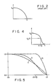
- Figure 2 depicts a standard parabolic profile used in the prior art (see Ziegler, supra ).
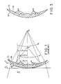
- Figure 3 shows a diffractive bifocal optical lens containing facets according to the design illustrated in Figure 4.
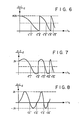
- Figure 4 illustrates a new cosine profile used in one embodiment of this invention.
- Figure 3 comprises an optical lens CL possessing anterior surface AS and peripheral posterior surface PS .
- the posterior surface of the optic zone is comprised of the diffractive facets (echelettes) E and their corresponding non-optical edges N .
- This particular profile is drawn in Figure 4.
- Figure 5 is an overlay of the parabolic echelette design a characteristic of the prior art (see Figure 2), the cosine profile b of Figure 4 and another useable profile c for a bifocal lens.
- the purpose of the overlay is to illustrate the profile differences between the structures of the invention and the prior art illustrated by Figure 2. Note particularly the shift in profile of curve b at the ⁇ n spacing. That small difference allows the profile of curve b to be suitably employable as the facet profile for the lens element of the invention.
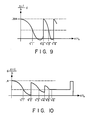
- Figures 6 through 10 depict a variety of useful facet profiles that can be used according to the invention in the lens construction of Figure 2.
- Figure 6 graphically depicts along an x-y axis the profile of Figure 4 in a repetitive sequence of alternating half-period inclined zones represented by the odd and the even zones.
- Figure 7 is another profile graphically depicted along an x-y axis in which the depth of the non-refractive edges of the step are further reduced to 0.31 ⁇ and the depth of the even half-period zones have a curved connection with the non-refractive edge.
- Figure 8 shows a profile where the edge of the step is inclined, suggesting that it contributes to the optical quality of the phase zone plate.
- the profiles of the half-period alternating zones in this embodiment are different from the preceding designs, mainly because the non-refractive edge has been substantially removed.
- Figure 9 shows a faceted profile where the inclination of the even zones have a bottom curvature which presents two opposite-facing curves before connecting with the non-refractive edge of the step.
- Figure 10 shows another facet profile that incorporates two phase zone plates and a pure refractive portion.
- there is a decrease in depth from full-period zone to full-period zone though it is not necessary for the decrease to exist throughout the optic zone.
- the first half of the full-period zones of the optic zone may be only one depth, and the second half of the full-period zones may be progressively reduced in depth.
- each of the steps, whether of the same or different depth is equally divided along a common plane of the optic zone.
- the pure refractive portion is preferably in the form of one or more channels which may be incorporated within the optic zone and/or circumscribing the optic zone.
Abstract
Description
- A diffractive multifocal optical element comprising a phase zone plate containing annular concentric zones in which the zones are spaced substantially proportional to √n, the zones possess stepped facets that introduce a discontinuity in optical path length of less than λ/2. The invention also embraces a phase zone plate containing annular concentric zones possessing facets which provide an alternating stepped repetitive pattern in accordance with √n spacing in the optical element and wherein the depth of the steps of the facets are less than λ/2(η′-η), where η′ and η are the indices of refraction of the lens and the medium in which the lens is interacting and λ is the design wavelength.
- This invention relates to an improvement in phase zone plate optics embracing contact and intraocular lenses. A "phase zone plate", as employed herein and in the claims, is a unitary optical region of a lens utilizing the combination of a zone plate and optical facets (such as in the form of echelettes) in the zones of the zone plate, and the combined facets in the zones diffract light to produce a specific wavefront which results in a specific intensity distribution of light at a variety of orders (e.g., 0th, 1st, etc.) of the zone plate. The orders constitute the foci of the zone plate. In a restrictive sense and also in the most utilitarian sense, the phase zone plate is designed for general lens applications where the distribution of light at effective intensities is dependent upon zone spacing for yellow light. Yellow light, as employed herein, is that portion of the visible spectrum at 530-570 manometers.
- This invention relates inter alias to contact lenses. Contact lenses are classical vergence type lenses. They possess a concave corneal bowl (the posterior surface) that allows fitting to the eye and the outer surface (the anterior surface) is smooth and shaped to allow the eyelid to slide over the eye and to provide proper vergence of light (taking the lens material's refractive index into consideration) to a focal point accommodating to the eye. The majority of the commercial contact lenses are shaped such that the lenses are thinnest about the optical axis and the depth of the lenses gradually increases along a sloped radial length extending in the direction of the lens perimeter. Owing to the difference in depth extending from the optical axis, light passing through the optical axis has to pass through less of the lens material. Because light travels faster in air, the light passing through greater depths relative to light passing through lesser depths will be shifted, hence be retarded in time.¹ Consequently, the shape of the lens is selected to accommodate this progressive retardation of the light so that the lightwaves emanating from the posterior surface are in synchronization in reaching a desired focal point.
- (1. See Fincham, et al., Optics, Published by Butterworths, London, 9th edition, 1980, 1981, pages 72-75.)
- This invention concerns contact lenses utilizing phase zone plate optics, such as phase zone plate bifocals and "tuned" Fresnel lenses making use of concentric annular zones. Such lenses generally follow the designs described, for example, by Allen L. Cohen in U.S. 4,210,391; 4,338,005; and 4,340,283 ("Cohen patents"). A Cohen lens design provides that the radii "rn" of the annular and concentric zones are substantially proportional to √n and that the zones are cut so as to direct light to more than one focal point.
- The Cohen lens design with phase zone plate optics allows bifocal lens constructions which are exceptionally thin. Contact lenses may be designed with phase zone plate optics in order to achieve a bifocal or other multifocal effects. The specific chromatic properties of a phase zone plate may be incorporated in the design of a contact lens including a contact lens having multifocal properties. All phase zone plate optical elements which are designated bifocals are possessed inherently with the ability to focus light to more than two focal points. They are designated bifocals because the intensity levels of the light to any two orders, e.g., the 0th and 1st order focal points are adequate for bifocal applications. In that sense, every bifocal distributes light to a third, and possibly more, focus. The judgment of whether a lens is a bifocal or trifocal is not based on any strict rule. If the wearer of the lens does not find objectionable the presence of the third or more focuses, then the lens is probably adequate as a bifocal. (See Klein and Ho, SPIE, August 1986, Table 2 and the comments about Table 2.)
- Other references mentioning or suggesting phase zone plate optics in regards to contact lenses are G. Forst, "Research into the Usability of Circular Grids as Aid to Vision,"Der Augenoptiker, 1966 (12), pages 9-19; Ziegler, "Fabrication or Correction of Optical Lenses," as modified by Cohen, see
column 4, lines 27-36 of Cohen, U.S. Patent No, 4,339,005, and column 5, line 63 to column 6, line 68, of Cohen, U.S. Patent No, 4,210,391; Freeman, U.S. 4,637,697; and Freeman, U.S. 4,642,112 (to the extent that holography embraces phase zone plate optics). - Bifocal contact lenses utilizing the above principles of phase zone plate optics are commercially available. Such lenses are believed to utilize stepped annular facets each comprising a full-period zone where each zone has a depth of an optical path length of λ/2, providing a physical depth of λ/2(η′-η). η′andη are the indices of refraction of the lens and the medium (e.g., lachrymal layer) in which the lens is interacting and λ is the design wavelength, in this case that of yellow light. This results in a bifocal contact lens where the 0th and 1st orders have an equal split of yellow light intensity at about 40.1%.
- A full-period zone, for purposes of this invention, is defined as the smallest repetitive sequence of facets within a phase zone plate which are spaced substantially proportional to √n. Such spacing is characterized by the formula:
rn≃√2 n d λ
where d represents the 1st order focal length. A half-period zone, for the purposes of this invention, is characterized by the formula:
rn≃√n d λ
where d represents the 1st order focal length. - Though the non-refractive step wall or riser to the plateau of the step is cylindrical or nearly cylindrical in the planar direction of the optical axis of the lens, and thereby occupies a small fraction of the lens phase zone plate surface area, it is regarded to be sufficiently large to contribute to a number of problems. Image shadowing and debris trapping are some of the problems that could be made less acute by reducing depth of the step wall or riser.
- However, if such a lens were altered to reduce the depth of the facet³ to a value less than λ/2, λ being the design wavelength, the optical qualities of the lens quickly becomes very poor. Though one is dealing with very small values when working at λ/2, a few millimicrons change in dimension seriously impacts on lens performance. For example, a 10% reduction in the depth of the depth of the facets yields a significant loss of effective bifocality in such a lens. It should be appreciated that all other values relating to the phase zone plate's dimensions are commensurately small. The plateau of the facet extending from the non-refractive step to the nadir of an adjacent non-refractive step, loses thickness from the λ/2 depth to a zero depth at the nadir of the adjacent step. These facts suggest that there is little one can do to avoid the loss in bifocality when reducing the depth of the step below λ/2.
- (3. The terms "depth of a facet," "depth of the steps of the facet," "depth of the step" and words to that effect, as used herein, means in relation to the design wavelength of the lens, the degree of discontinuity in optical path length generated by the step.)
- It has been discovered that small changes (in some embodiments exceptionally small changes) in the configuration of the shape of inclination of the plateaus of the facets within the framework of √n spacing provides that one can generate an effective bifocal lens based on phase zone plate optics where the depth of the step is less than λ/2. Through the alternating inclinations of facets embodied in the Cohen patents and the Cohen lens design, one can provide excellent bifocality in a contact lens where the facets have a depth less than about λ/2.
- There is characterized herein a novel bifocal lens construction which provides the advantages of rn zone spacing and stepped facets that introduce a discontinuity in optical path length of less than λ/2.
- There is characterized herein a novel bifocal lens construction which reduces image shadowing attendant with conventional bifocal lenses containing stepped facets having a depth greater or equal to λ/2.
- There is characterized herein a novel bifocal contact lens having a phase zone plate which possesses less volume for tear collection than a bifocal contact lens having a conventional λ/2 parabolic echelette configuration. This means that the contact lenses of the invention have less volume for the trapping of debris on the eye and between the eye and the lens.
- There are lens constructions according to this invention which provide surface contact with the cornea in a manner such that facet curves of the phase zone plate tangentially touch the cornea's surface. This causes the novel lens of the invention to rest more comfortably on the eye.
- There is described herein a bifocal contact lens utilizing phase zone plate optics and a facet depth less than one-half the wavelength of the designed wavelength, where the primary focal points are at two orders, such as the 0th and 1st orders, the 0th and 2nd orders, or any other combination of two orders.
- The invention relates to a diffractive multifocal optical element comprising a phase zone plate containing annular concentric zones in which the zones are spaced substantially proportional to √n and the zones possess stepped facets that introduce a discontinuity in optical path length of less than λ/2 where λ is the design wavelength.
- The invention encompasses a phase zone plate containing annular concentric zones possessing facets which provide an alternating stepped repetitive pattern in accordance with √n spacing in the optical element and wherein the depth of the steps of the facets are less than λ/2(η′-η), where η′and η are the indices of refraction of the lens and the medium in which the lens is interacting and λ is the design wavelength.
- In a particular embodiment of the invention, the optical element comprises facets within the annular concentric zones providing an alternating stepped repetitive pattern wherein:
- 1. the facet of one of the alternating zones has an inclined curved profile that is interrupted at the zone boundary by another curved profile providing the differently inclined curved facet of the other alternating zone,
- 2. the zones are spaced substantially proportional to √n,
- 3. the depth of the facets are less than λ/2,
- 4. the zones are cut so as to direct yellow light to at least two primary focal points in at least adequate intensities for visual usage at each such primary focal point, and,
- 5. but for the alternating pattern, the element would not have such intensity.
- The invention encompasses a bifocal optical element of the Cohen lens design wherein the odd and even zones of the phase zone plate
- a. conform to rn≃√
n d λ spacing, - b. are contiguous and free of a non-refractive step interface at at least every other zone boundary, and leave a sloped profile at such contiguous interface,
- c. the cross-section of each odd zone has the same general profile and the cross-section of each even zone has the same general profile,
- d. the general profile of the odd zones is different from that of the even zones, and
- e. the depth of steps for the zones are less than λ/2.
- Preferably, the slope profile provides a smooth transsition from zone to zone.
- In another aspect, the invention encompasses a bifocal optical element of the Cohen design comprising a faceted step phase zone plate containing an alternating profile wherein:
- a. the phase zone plate conforms to rn≃√
2 n d λ ; - b. the alternating profile occurs within the full-period spacing;
- c. the facets have a depth less than about λ/2;
- d. the zones are cut so as to direct yellow light to at least two primary focal points in at least adequate intensity for visual usage at each such primary focal point, and
- e. but for such alternating profile the zones would not have such intensity for visual usage.
- In a preferred embodiment, the optical element of the invention comprises optically diffractive facets providing two different curved profiles that are joined at radii rn through transition profiles located about such radii, which transition profiles have profile curvatures that are different from said two different curved profiles whereby to form annular and concentric zones at such transition profiles which zones are spaced substantially proportional to √n and the zones are cut so as to direct yellow light to at least two primary focal points in at least adequate intensity for visual usage at each such primary focal point, which element but for the curved profiles would not have such intensity for visual usage.
- This invention relates to an ophthalmic lens such as contact and intraocular lenses containing such optical elements. In a preferred embodiment of the invention, the ophthalmic lens is a bifocal lens that splits the light to two focal points in essentially equal intensities. In a most preferred embodiment of the invention, the optical element of the lens comprises a repetitive pattern of zones having a profile embraced by the equation
d = Do · {1/2 + 1/2 · cos (π · r²/b²)}
where d is the depth of the repetitive profile, r is the radial position of the zone, b is the radius of the 1st zone, and D o is the facet depth for the design wavelength. - One embodiment of the invention is directed to an ophthalmic contact lens containing at least two phase zone plates within its optic zone, at least one of which embraces the features of the aforementioned optical elements.
- Another embodiment of the invention is directed to an ophthalmic contact lens having within its optic zone, (1) a phase zone plate embracing the features of the aforementioned optical elements and (2) a pure refractive portion, preferably in the form of one or more channels.
-
- Figure 1 illustrates an incident plane wave striking a diffractive bifocal optical element illustrating the typical parabolic shaped echelettes, having the √n spacing pattern of the Cohen lens design, whereupon it is transformed into two (2) emergent spherical waves directed to different foci, thus depicting the general principles of multifocal diffraction.
- Figure 2 is a curve illustrating the echelette profile cut from a typical prior art diffractive bifocal optical element, such as in a lens according to Ziegler, supra. The axis labeled d represents the echelette thickness and the axis labeled r represents the radial distance along the echelette.
- Figure 3 is a cross-section of one embodiment of optical element in accordance with the invention, the facets of which are depicted graphically in Figure 4.
- Figure 4 is a curve illustrating a facet profile of one embodiment of the invention. The axis labeled d represents facet thicknesses and the axis labeled r represents the radial distance along the facets.
- Figure 5 compares the graphical profiles of the full-period spaced echelette zone of the prior art possessing the conventional parabolic profile and the half-period spaced facet zones containing a multi-profile interrupted structure.
- Figures 6 through 12 provide graphical depictions of cross-sectional views of a variety of facet arrangements for optical elements within the scope of this invention.
- This invention concerns inter alia bifocal optical lenses comprising an optic zone section which uses diffractive means for achieving multifocal properties. The diffractive means incorporates a repetitive pattern with shallow facet depths and a new profile. The use of a profile with shallow facet depths reduces shadowing of images, debris collection between the phase plate and the eye (in the case with contact lenses), and enhances wearer comfort in the case with contact lenses.
- The invention finds its most favored employment in contact lenses. The invention involves incorporating the optical elements on the anterior or posterior portion, or both, of a contact lens. The optical elements may be provided on contact lenses by lathing or molding. The invention is favorably employed in multifocal (especially bifocal) intraocular lens.
- The present invention relates to a diffraction bifocal optical element. It utilizes a circularly blazed diffraction grating to achieve its multifocal properties as taught by Cohen. The blazed grating allows for adjusting the split of light between two focal points by adjusting both the facet depth Do and the profile of the blazed facet itself. The invention utilizes novel profiles for the facets of the optical element.
- The present invention relates to a diffraction bifocal optical element utilizing a circularly blazed diffraction grating to achieve its multifocal properties wherein the blazed grating allows for adjusting the split of light between two focal points by adjusting both the facet depth Do and the profile of the blazed facet itself, and the blazed facet provides an alternating inclination divided in accordance with √n zone spacing.
- The novel facet arrangements of the invention divide what in the prior art is considered a full-period (λ) spacing of the facets into alternating inclined half-period (λ/2) faceted zones that contain only one non-refractive cylindrical (or essentially cylindrical) surface for every two alternating half-period zones, and such two alternating half-period zones are interconnected by a smooth surfaced facet which effects a phase shift of the design wavelength light between the half-period zones. All of the non-refractive essentially cylindrical or cylindrical surfaces are less than λ/2 deep. The alternating zones of the invention provide control of the split of light between the focal points of the lens. By adjustment of the inclinations of the alternating zone, it is possible to vary the intensity of light to the focal points.
- The invention embraces a diffraction bifocal optical element superimposed on, etched into and/or embedded within a surfaces layer of a lens possessing the ability to independently converge light to at least two (preferably two) primary focal points in which the element comprises alternating inclined half-period (λ/2) faceted zones that contain only one non-refractive cylindrical (or essentially cylindrical) surface for every two alternating half-period zones, and such two alternating half-period zones are interconnected by a smooth surfaced facet which effects a phase shift of the design wavelength light between the half-period zones. All of the non-refractive essentially cylindrical or cylindrical surfaces are less than λ/2 deep.
- A remarkable aspect of the invention is the minimal difference in inclination required in the alternating facets to achieve the benefits of excellent intensity of light at the designed focal points and at the same time yield the improvements cited above, including glare and/or haloing reduction. Only a small difference in inclinations from a traditional parabolic shape is required in the half-period zones to generate a lens providing the advantages of the invention. Such small differences come about by reason of the smallness of the facets even over a full-period zone measurement. For example, one embodiment of the invention may employ in a contact lens
◇ where the phase plate is characterized as comprising 8 full-period zones and is located in the posterior surface of the lens,
◇ the lens conforms to the shape of the eye and provides a typical refraction to the distant focal point, and
◇ the design wavelength is for yellow light, about 555 nanometers,
the following dimensions:
■ the first zone at the optical axis has a radius of about 0.75 millimeters;
■ the last zone away from the optical axis has a width defined by the difference in the radius to the outer periphery of the zone and the radius to the inner periphery of the zone, of about 0.14 millimeters; and
■ the depth of each facet is about 0.003 millimeters. - This same structure, measured however, in terms of its 16 half-period zone spacings caused by a profile surfaces inflection occuring at a point at about √n dimensions:
■ the first zone at the optical axis has a radius of 0.053 millimeters;
■ the last zone away from the optical axis has a width defined by the difference in the radius to the outer periphery of the zone and the radius to the inner periphery of the zone, of about 0.067 millimeters. - On comparing the optical elements comprising facets that have a conventional parabolic shape over full-period zone spacing to optical elements comprising the half-period zone spacing and facet profiles of the invention, utilizing the depth of the step of 0.003 millimeter, the half-period zone spacing is found to have a slightly lower area under the curves reflecting the profile of the facets. That difference can be as little as about 1% area difference to about 10 % area difference. Typically the difference is about 2 to about 5% area difference. In the above illustration, the area difference is about 3%. As small as the area difference seems to be, its contribution to the performance of the lens is quite significant.
- A lens having the prior art parabolic shaped echelettes, full-period spacing and with an echelette depth of 0.8 λ/2, provides the following light intensity distribution:
-1 0 1 .05 .57 .25 m = 3. nonalternating (b = .5) -4 .0050 -3 .0083 -2 .0162 -1 .0450 0 .4053 1 .4053 2 .0450 3 .0162 4 .0083 - Each facet of the alternating zones of the phase zone plate has a depth less than λ/2, where λ is the design wavelength of the phase zone plate. In those cases where one zonal facet is joined by a curved profile to another zonal facet, if only one of them is formed from a step riser representing a non-refractive surface, the two zonal facets will have a combined depth of less than λ/2. In this special case, and for convenience of calculations, the depth of the combination is viewed from the concept of full-period zone spacing. However, such alternating inclined zonal facets are viewed as having a variable depth. The depth of the facets may range from about 0.01 to about 0.99 times (x) λ/2, preferably about 0.05 to about .95 x λ/2, most preferably about 0.1 to about 0.9 xλ/2.
- Assuming arguendo it was logical to those in the art to want to reduce facet depth, until this invention, there was no reasonable way to form a diffractive bifocal with facet (echelette) depths shallower than 1/2 wavelength that would not adversely affect the energy split between the two emergent spherical waves.
- This invention makes it possible to construct shallow facet (echelette) diffractive bifocal lenses with the requisite equal, or substantially equal, energy split between the two spherical waves going to the zeroth and first orders.
- This invention supports the novel concept that the energy split between the two emergent spherical waves is determined
- 1. by the facet (echelette) depths and
- 2. the actual facet (echelette) profile.
- With respect to Figure 1, there is described a diffractive bifocal lens CL with a curvature to effect convergent refraction and diffraction. In the figure, optical elements E (predicated on a presumed full-period spacing) transform an incident plane wave into a wave front predominately of two spherical waves. For example, incident light wave with planar phase fronts P passes through the anterior surface AS of lens CL and emerges from the posterior surface PS as a light wave of predominately the two spherical phase front S₁ and S₂ with intensities I₁ and I₂, respectively. The posterior surface PS contains diffractive echelettes E and their corresponding non-optical edges N. The facet (echelette) spacing in a diffractive optical element is given by the standard formula
rn ≃√n · r₁
in which rn is the radius of the nth zone (utilizing full-period spacing). And η and η′ are the refractive indices of air and the lens CL, respectively. The location of the focal points of the two spherical wavefronts is determined by the radius of the first zone r₁ and the carrier power of lens CL. In particular, the nth order focal point fm is given by the equation
fm = (r₁)²/(2 ·λ · m)
with λ = wavelength; and m = 0, ±1, ±2, etc. - A desirable energy split has been suggested to occur when the two emergent spherical waves carry equal amounts of the total energy, that is, when I₁ = I₂. The current literature states that this is the case when the facet (echelette) depths Do are set at 1/2 wavelength deep (see the Klein and Ho, supra).
- Figure 2 depicts a standard parabolic profile used in the prior art (see Ziegler, supra). The depth d of the repetitive profile as a function of radial position r is shown in the following equation:
d = Do · (1 - r²/b²) b = radius of the 1st zone
This profile is repeated in each zone but scaled down proportionally to the width of each such zone. The facet (echelette) depth for an equal energy split at the 0th and 1st orders is shown by the following equation:
Do = 0.500 · λ/(n-1) n = index of refraction
and the intensity split is given by
I₁ = I₂ = (2.0/π)² = 0.405. - Figure 3 shows a diffractive bifocal optical lens containing facets according to the design illustrated in Figure 4. The facet depths are .405/.500 = 80% of the depths required by prior art lenses.
- Figure 4 illustrates a new cosine profile used in one embodiment of this invention. The repetitive profile is given by
d = Do · {1/2 + 1/2 · cos (π· r²b²)} - The facet depth, utilizing a full-period spacing between the non-refractive edges of the steps but containing alternatingly inclined facets within half-period spacing, for an equal energy split is given by
Do = 0.405 · λ/(n-1)
and the intensity split is given by
I₁ = I₂ = J
where Jo is a bessel function. - Figure 3 comprises an optical lens CL possessing anterior surface AS and peripheral posterior surface PS. In this embodiment the posterior surface of the optic zone is comprised of the diffractive facets (echelettes) E and their corresponding non-optical edges N. The physical profile of the facets (echelettes) E is given by
d = Do · {1/2 + 1/2 · cos (π · r²/b²)}
where d is the thickness of the facet (echelette), r is the radial distance from the inner edge of the zone (and such profile is repeated in each zone but scaled down proportionally to the width of each such zone) within which the facet (echelette) is formed and the occurrence of such profile alternation, and b is the radius of the first zone. This particular profile is drawn in Figure 4. - Figure 5 is an overlay of the parabolic echelette design a characteristic of the prior art (see Figure 2), the cosine profile b of Figure 4 and another useable profile c for a bifocal lens. The purpose of the overlay is to illustrate the profile differences between the structures of the invention and the prior art illustrated by Figure 2. Note particularly the shift in profile of curve b at the √n spacing. That small difference allows the profile of curve b to be suitably employable as the facet profile for the lens element of the invention.
- The physical profile of the facet c is given by
y = 1 - {(r² - 1/√2)/(1 - 1/√2)} r>1/√2
- Profiles a and c at such reduced depth fail to give an equal intensity split of the light to the 0th and 1st orders whereas they do when
Do = 0.500 · λ/(n-1). - Figures 6 through 10 depict a variety of useful facet profiles that can be used according to the invention in the lens construction of Figure 2.
- Figure 6 graphically depicts along an x-y axis the profile of Figure 4 in a repetitive sequence of alternating half-period inclined zones represented by the odd and the even zones. This particular embodiment is characterized by
y = 0.405λ/(n - 1) · {1/2 + 1/2 cos (πr²/2r
Io = I₁ = 0.402
wherein λ is the designed wavelength and n is the index of refraction of the lens medium. - Figure 7 is another profile graphically depicted along an x-y axis in which the depth of the non-refractive edges of the step are further reduced to 0.31λ and the depth of the even half-period zones have a curved connection with the non-refractive edge. This embodiment of the invention is characterized by
y = 0.314λ/(n - 1) · 2.5{1/2 + 1/2 cos (πr²/2r

Io = I₁ = 0.390 - Figure 8 shows a profile where the edge of the step is inclined, suggesting that it contributes to the optical quality of the phase zone plate. The profiles of the half-period alternating zones in this embodiment are different from the preceding designs, mainly because the non-refractive edge has been substantially removed. This embodiment is characterized by
y = λ/(n - 1){r²/r

Io = I₁ = 0.314
It is to be noted in this embodiment that the depths of the facets for the odd zones were further reduced to 0.21λ but the even zones have a depth below the nadir of the odd zones by another 0.21λ. - Figure 9 shows a faceted profile where the inclination of the even zones have a bottom curvature which presents two opposite-facing curves before connecting with the non-refractive edge of the step. This embodiment of the invention is characterized by
y = 0.394λ/(n - 1){0.287 + 0.731Jo{4.20·r²/2r
I₀ = I₁ = 0.402
wherein Jo is a bessel function. - Figure 10 shows another facet profile that incorporates two phase zone plates and a pure refractive portion. In this embodiment, there is a decrease in depth from full-period zone to full-period zone, though it is not necessary for the decrease to exist throughout the optic zone. For example, the first half of the full-period zones of the optic zone may be only one depth, and the second half of the full-period zones may be progressively reduced in depth. In the preferred modes of such embodiments, each of the steps, whether of the same or different depth, is equally divided along a common plane of the optic zone. The pure refractive portion is preferably in the form of one or more channels which may be incorporated within the optic zone and/or circumscribing the optic zone. The particular embodiment of Figure 10 is characterized by
y = αλ/(n - 1){1/2 + 1/2cosπ/2 · r²/r
- The faceted profiles of Figures 11 and 12 introduce a space reduction in the full period zone at q₁ which allows the step to proceed from q₁ to r², etc. This space reduction in the alternating zone is not regarded to alter the √n spacing of the zones. Figure 11 is characterized by
yn =.40{1/2 + 1/2 cos[(π/qn² - rn²) (r² - rn-1²)]}
where rn-1 < r < qn
yn = .40{1/2 + 1/2 sin[π/rn² - qn² · (r² - (r n² + qn²)/2)]}
where qn < r < rn-1
rn≃√2 n d λ
qn = rn-1 + (rn - rn-1/α)
α = 1.086
Figure 12 is characterized
yn = .39{1/2 + 1/2 cos[π/qn² - rn² · (r² - rn-1²)]}
where rn-1 < r < qn
yn =.39{1 - (r - rn/rn - qn)²}
where qn < r < rn
rn≃√2 n d λ
qn = rn-1 + (rn - rn-1/α)
α = 1.086. - It should be appreciated that the invention is not limited to the exact details of construction shown and described herein for many obvious modifications will occur to persons skilled in the art. In particular, many different profiles may be determined which allow the reduction of facet (echelette) depths without changing the desirable equal energy split. However, the choice of facet profile is not dependent upon effecting an equal energy split. It is believed that the achievement of the energy splits, whether equal or not, is directly derived from the alternating inclinations of the half-period zones.
Claims (11)
d = Do · {1/2 + 1/2 · cos (π· r²b²)}
where d is the depth of the repetitive profile, r is the radial position of the zone, b is the radius of the 1st zone, and D o is the facet depth for the design wavelength.
Priority Applications (1)
| Application Number | Priority Date | Filing Date | Title |
|---|---|---|---|
| EP95111167A EP0681198A1 (en) | 1988-07-20 | 1988-11-10 | Multifocal ophthalmic lens |
Applications Claiming Priority (2)
| Application Number | Priority Date | Filing Date | Title |
|---|---|---|---|
| US22200088A | 1988-07-20 | 1988-07-20 | |
| US222000 | 1988-07-20 |
Related Child Applications (1)
| Application Number | Title | Priority Date | Filing Date |
|---|---|---|---|
| EP95111167.3 Division-Into | 1988-11-10 |
Publications (3)
| Publication Number | Publication Date |
|---|---|
| EP0351471A2 true EP0351471A2 (en) | 1990-01-24 |
| EP0351471A3 EP0351471A3 (en) | 1990-07-25 |
| EP0351471B1 EP0351471B1 (en) | 1996-01-31 |
Family
ID=22830316
Family Applications (2)
| Application Number | Title | Priority Date | Filing Date |
|---|---|---|---|
| EP95111167A Withdrawn EP0681198A1 (en) | 1988-07-20 | 1988-11-10 | Multifocal ophthalmic lens |
| EP88310562A Expired - Lifetime EP0351471B1 (en) | 1988-07-20 | 1988-11-10 | Multifocal diffractive optical device |
Family Applications Before (1)
| Application Number | Title | Priority Date | Filing Date |
|---|---|---|---|
| EP95111167A Withdrawn EP0681198A1 (en) | 1988-07-20 | 1988-11-10 | Multifocal ophthalmic lens |
Country Status (14)
| Country | Link |
|---|---|
| US (1) | US4995715A (en) |
| EP (2) | EP0681198A1 (en) |
| JP (1) | JP2849097B2 (en) |
| KR (1) | KR0141607B1 (en) |
| CN (1) | CN1020134C (en) |
| AT (1) | ATE133796T1 (en) |
| AU (1) | AU622420B2 (en) |
| CA (1) | CA1316727C (en) |
| DE (1) | DE3854966T2 (en) |
| ES (1) | ES2081811T3 (en) |
| GR (1) | GR3019724T3 (en) |
| IE (2) | IE73484B1 (en) |
| IL (1) | IL88350A (en) |
| ZA (1) | ZA888416B (en) |
Cited By (23)
| Publication number | Priority date | Publication date | Assignee | Title |
|---|---|---|---|---|
| EP0355230A2 (en) * | 1988-08-26 | 1990-02-28 | Allen L. Dr. Cohen | Method of producing a multifocal diffractive optical element |
| EP0470811A2 (en) * | 1990-08-08 | 1992-02-12 | Minnesota Mining And Manufacturing Company | Multifocal diffractive ophthalmic lenses |
| US5225858A (en) * | 1987-06-01 | 1993-07-06 | Valdemar Portney | Multifocal ophthalmic lens |
| EP0605841A1 (en) * | 1993-01-06 | 1994-07-13 | Holo-Or Ltd. | Diffractive multi-focal lens |
| WO1997044698A1 (en) * | 1996-05-21 | 1997-11-27 | Allergan Sales, Inc. | Enhanced monofocal intraocular lens |
| US5702440A (en) * | 1996-01-26 | 1997-12-30 | Allergan | Multifocal ophthalmic lens for dim-lighting conditions |
| US5724258A (en) * | 1996-05-09 | 1998-03-03 | Johnson & Johnson Vision Products, Inc. | Neural network analysis for multifocal contact lens design |
| US6210005B1 (en) | 1999-02-04 | 2001-04-03 | Valdemar Portney | Multifocal ophthalmic lens with reduced halo size |
| US6231603B1 (en) | 1998-11-10 | 2001-05-15 | Allergan Sales, Inc. | Accommodating multifocal intraocular lens |
| WO2014008343A1 (en) * | 2012-07-03 | 2014-01-09 | Abbott Medical Optics Inc. | High efficiency optic |
| US9011532B2 (en) | 2009-06-26 | 2015-04-21 | Abbott Medical Optics Inc. | Accommodating intraocular lenses |
| US9039760B2 (en) | 2006-12-29 | 2015-05-26 | Abbott Medical Optics Inc. | Pre-stressed haptic for accommodating intraocular lens |
| US9271830B2 (en) | 2002-12-05 | 2016-03-01 | Abbott Medical Optics Inc. | Accommodating intraocular lens and method of manufacture thereof |
| US9421089B2 (en) | 2007-07-05 | 2016-08-23 | Visiogen, Inc. | Intraocular lens with post-implantation adjustment capabilities |
| US9504560B2 (en) | 2002-01-14 | 2016-11-29 | Abbott Medical Optics Inc. | Accommodating intraocular lens with outer support structure |
| US9603703B2 (en) | 2009-08-03 | 2017-03-28 | Abbott Medical Optics Inc. | Intraocular lens and methods for providing accommodative vision |
| US9636213B2 (en) | 2005-09-30 | 2017-05-02 | Abbott Medical Optics Inc. | Deformable intraocular lenses and lens systems |
| US9814570B2 (en) | 1999-04-30 | 2017-11-14 | Abbott Medical Optics Inc. | Ophthalmic lens combinations |
| US9968441B2 (en) | 2008-03-28 | 2018-05-15 | Johnson & Johnson Surgical Vision, Inc. | Intraocular lens having a haptic that includes a cap |
| US9987125B2 (en) | 2012-05-02 | 2018-06-05 | Johnson & Johnson Surgical Vision, Inc. | Intraocular lens with shape changing capability to provide enhanced accomodation and visual acuity |
| US10722400B2 (en) | 2011-09-12 | 2020-07-28 | Amo Development, Llc | Hybrid ophthalmic interface apparatus and method of interfacing a surgical laser with an eye |
| WO2021245506A1 (en) * | 2020-06-01 | 2021-12-09 | Icares Medicus, Inc. | Double-sided aspheric diffractive multifocal lens, manufacture, and uses thereof |
| US11707354B2 (en) | 2017-09-11 | 2023-07-25 | Amo Groningen B.V. | Methods and apparatuses to increase intraocular lenses positional stability |
Families Citing this family (122)
| Publication number | Priority date | Publication date | Assignee | Title |
|---|---|---|---|---|
| US5144483A (en) * | 1986-05-14 | 1992-09-01 | Cohen Allen L | Diffractive multifocal optical device |
| US4881805A (en) * | 1987-11-12 | 1989-11-21 | Cohen Allen L | Progressive intensity phase bifocal |
| JPH04361201A (en) * | 1991-06-10 | 1992-12-14 | Olympus Optical Co Ltd | Optical system using fresnel zone plate |
| US5629799A (en) * | 1992-07-16 | 1997-05-13 | Asahi Kogaku Kogyo Kabushiki Kaisha | Chromatic aberration correcting element and its application |
| US5344447A (en) * | 1992-11-12 | 1994-09-06 | Massachusetts Institute Of Technology | Diffractive trifocal intra-ocular lens design |
| US5699142A (en) * | 1994-09-01 | 1997-12-16 | Alcon Laboratories, Inc. | Diffractive multifocal ophthalmic lens |
| US5801889A (en) * | 1995-08-16 | 1998-09-01 | Eastman Kodak Company | Technique to eliminate scattered light in diffractive optical elements |
| US6259668B1 (en) * | 1996-02-14 | 2001-07-10 | Samsung Electronics Co., Ltd. | Recording/reproducing apparatus having an optical pickup device to read from and record information to disks of different thicknesses |
| US6222812B1 (en) | 1996-08-29 | 2001-04-24 | Samsung Electronics Co., Ltd. | Optical pickup using an optical phase plate |
| US6639889B1 (en) | 1997-02-13 | 2003-10-28 | Samsung Electronics Co., Ltd. | Recording/reproducing apparatus including an optical pickup having an objective lens compatible with a plurality of optical disk formats |
| US6304540B1 (en) * | 1998-03-30 | 2001-10-16 | Samsung Electronics Co., Ltd. | Optical pickup compatible with a digital versatile disk and a recordable compact disk using a holographic ring lens |
| US5980040A (en) * | 1997-06-30 | 1999-11-09 | Wesley Jessen Corporation | Pinhole lens and contact lens |
| US6158862A (en) * | 1997-12-04 | 2000-12-12 | Alcon Laboratories, Inc. | Method of reducing glare associated with multifocal ophthalmic lenses |
| JP3827860B2 (en) * | 1998-03-31 | 2006-09-27 | パイオニア株式会社 | Objective lens and optical pickup device |
| WO2000008516A1 (en) | 1998-08-06 | 2000-02-17 | Lett John B W | Multifocal aspheric lens |
| EP1147448A4 (en) * | 1998-12-16 | 2008-12-10 | Novartis Ag | Multifocal contact lens with aspheric surface |
| US6790232B1 (en) | 1999-04-30 | 2004-09-14 | Advanced Medical Optics, Inc. | Multifocal phakic intraocular lens |
| US6616692B1 (en) | 1999-04-30 | 2003-09-09 | Advanced Medical Optics, Inc. | Intraocular lens combinations |
| US6406494B1 (en) | 1999-04-30 | 2002-06-18 | Allergan Sales, Inc. | Moveable intraocular lens |
| US6536899B1 (en) | 1999-07-14 | 2003-03-25 | Bifocon Optics Gmbh | Multifocal lens exhibiting diffractive and refractive powers |
| US6645246B1 (en) | 1999-09-17 | 2003-11-11 | Advanced Medical Optics, Inc. | Intraocular lens with surrounded lens zone |
| US6599317B1 (en) | 1999-09-17 | 2003-07-29 | Advanced Medical Optics, Inc. | Intraocular lens with a translational zone |
| US6551354B1 (en) | 2000-03-09 | 2003-04-22 | Advanced Medical Optics, Inc. | Accommodating intraocular lens |
| US6547822B1 (en) | 2000-05-03 | 2003-04-15 | Advanced Medical Optics, Inc. | Opthalmic lens systems |
| US6554859B1 (en) | 2000-05-03 | 2003-04-29 | Advanced Medical Optics, Inc. | Accommodating, reduced ADD power multifocal intraocular lenses |
| US6537317B1 (en) | 2000-05-03 | 2003-03-25 | Advanced Medical Optics, Inc. | Binocular lens systems |
| US6660035B1 (en) | 2000-08-02 | 2003-12-09 | Advanced Medical Optics, Inc. | Accommodating intraocular lens with suspension structure |
| US20030078657A1 (en) | 2001-01-25 | 2003-04-24 | Gholam-Reza Zadno-Azizi | Materials for use in accommodating intraocular lens system |
| US7780729B2 (en) | 2004-04-16 | 2010-08-24 | Visiogen, Inc. | Intraocular lens |
| US20030078658A1 (en) | 2001-01-25 | 2003-04-24 | Gholam-Reza Zadno-Azizi | Single-piece accomodating intraocular lens system |
| US8062361B2 (en) | 2001-01-25 | 2011-11-22 | Visiogen, Inc. | Accommodating intraocular lens system with aberration-enhanced performance |
| US6596025B2 (en) * | 2001-03-15 | 2003-07-22 | Valdemar Portney | Narrow profile intraocular lens |
| US6576012B2 (en) | 2001-03-28 | 2003-06-10 | Advanced Medical Optics, Inc. | Binocular lens systems |
| US6638305B2 (en) | 2001-05-15 | 2003-10-28 | Advanced Medical Optics, Inc. | Monofocal intraocular lens convertible to multifocal intraocular lens |
| ES2208077B2 (en) * | 2002-05-13 | 2005-05-16 | Universidad De Cantabria | MULTIFOCAL DIFRACTIVE ELEMENT AND MANUFACTURING METHOD. |
| KR20030093683A (en) * | 2002-06-05 | 2003-12-11 | 삼성전자주식회사 | Compatible optical pickup |
| US20040082993A1 (en) | 2002-10-25 | 2004-04-29 | Randall Woods | Capsular intraocular lens implant having a refractive liquid therein |
| US7896916B2 (en) | 2002-11-29 | 2011-03-01 | Amo Groningen B.V. | Multifocal ophthalmic lens |
| SE0203564D0 (en) | 2002-11-29 | 2002-11-29 | Pharmacia Groningen Bv | Multifocal opthalmic lens |
| US6951391B2 (en) * | 2003-06-16 | 2005-10-04 | Apollo Optical Systems Llc | Bifocal multiorder diffractive lenses for vision correction |
| US7287852B2 (en) * | 2003-06-30 | 2007-10-30 | Fiala Werner J | Intra-ocular lens or contact lens exhibiting large depth of focus |
| US20050027354A1 (en) * | 2003-07-28 | 2005-02-03 | Advanced Medical Optics, Inc. | Primary and supplemental intraocular lens |
| US20050030759A1 (en) * | 2003-08-04 | 2005-02-10 | Guide Corporation | Bifocal hyperbolic catadioptric collection system for an automotive lamp |
| US20050131535A1 (en) | 2003-12-15 | 2005-06-16 | Randall Woods | Intraocular lens implant having posterior bendable optic |
| DE102004025712A1 (en) * | 2004-05-26 | 2005-12-15 | Rupp + Hubrach Optik Gmbh | progressive lens |
| US7156516B2 (en) * | 2004-08-20 | 2007-01-02 | Apollo Optical Systems Llc | Diffractive lenses for vision correction |
| US7025456B2 (en) * | 2004-08-20 | 2006-04-11 | Apollo Optical Systems, Llc | Diffractive lenses for vision correction |
| US7506983B2 (en) | 2004-09-30 | 2009-03-24 | The Hong Kong Polytechnic University | Method of optical treatment |
| JP4926068B2 (en) * | 2004-10-25 | 2012-05-09 | アボット・メディカル・オプティクス・インコーポレイテッド | Ophthalmic lens having a plurality of phase plates |
| US7922326B2 (en) | 2005-10-25 | 2011-04-12 | Abbott Medical Optics Inc. | Ophthalmic lens with multiple phase plates |
| US8394084B2 (en) | 2005-01-10 | 2013-03-12 | Optimedica Corporation | Apparatus for patterned plasma-mediated laser trephination of the lens capsule and three dimensional phaco-segmentation |
| US7073906B1 (en) * | 2005-05-12 | 2006-07-11 | Valdemar Portney | Aspherical diffractive ophthalmic lens |
| US7947076B2 (en) | 2005-06-03 | 2011-05-24 | Medtronic Xomed, Inc. | Nasal valve treatment method and apparatus |
| US7441894B2 (en) * | 2006-02-09 | 2008-10-28 | Alcon Manufacturing, Ltd. | Pseudo-accommodative IOL having diffractive zones with varying areas |
| US7572007B2 (en) * | 2006-08-02 | 2009-08-11 | Alcon, Inc. | Apodized diffractive IOL with frustrated diffractive region |
| US8568478B2 (en) * | 2006-09-21 | 2013-10-29 | Abbott Medical Optics Inc. | Intraocular lenses for managing glare, adhesion, and cell migration |
| AU2007338100B2 (en) | 2006-12-22 | 2014-01-30 | Amo Groningen Bv | Accommodating intraocular lens, lens system and frame therefor |
| CA2674018C (en) | 2006-12-29 | 2015-05-26 | Advanced Medical Optics, Inc. | Multifocal accommodating intraocular lens |
| US7713299B2 (en) | 2006-12-29 | 2010-05-11 | Abbott Medical Optics Inc. | Haptic for accommodating intraocular lens |
| US9233023B2 (en) | 2007-03-13 | 2016-01-12 | Optimedica Corporation | Method and apparatus for creating ocular surgical and relaxing incisions |
| WO2008126339A1 (en) * | 2007-03-27 | 2008-10-23 | Itochu Aviation Co., Ltd. | Optical plate for imaging camera |
| US8740978B2 (en) * | 2007-08-27 | 2014-06-03 | Amo Regional Holdings | Intraocular lens having extended depth of focus |
| US9216080B2 (en) | 2007-08-27 | 2015-12-22 | Amo Groningen B.V. | Toric lens with decreased sensitivity to cylinder power and rotation and method of using the same |
| US8747466B2 (en) * | 2007-08-27 | 2014-06-10 | Amo Groningen, B.V. | Intraocular lens having extended depth of focus |
| US20090062911A1 (en) * | 2007-08-27 | 2009-03-05 | Amo Groningen Bv | Multizonal lens with extended depth of focus |
| US8974526B2 (en) | 2007-08-27 | 2015-03-10 | Amo Groningen B.V. | Multizonal lens with extended depth of focus |
| ATE523810T1 (en) * | 2008-02-15 | 2011-09-15 | Amo Regional Holdings | SYSTEM, GLASS LENS AND METHOD FOR EXPANDING THE DEPTH OF FOCUS |
| US8439498B2 (en) | 2008-02-21 | 2013-05-14 | Abbott Medical Optics Inc. | Toric intraocular lens with modified power characteristics |
| US8231219B2 (en) | 2008-04-24 | 2012-07-31 | Amo Groningen B.V. | Diffractive lens exhibiting enhanced optical performance |
| WO2009130610A2 (en) * | 2008-04-24 | 2009-10-29 | Amo Regional Holdings | Diffractive lens exhibiting enhanced optical performance |
| US7871162B2 (en) * | 2008-04-24 | 2011-01-18 | Amo Groningen B.V. | Diffractive multifocal lens having radially varying light distribution |
| US8862447B2 (en) | 2010-04-30 | 2014-10-14 | Amo Groningen B.V. | Apparatus, system and method for predictive modeling to design, evaluate and optimize ophthalmic lenses |
| US9335563B2 (en) | 2012-08-31 | 2016-05-10 | Amo Groningen B.V. | Multi-ring lens, systems and methods for extended depth of focus |
| JP5203160B2 (en) * | 2008-12-05 | 2013-06-05 | Hoya株式会社 | Diffractive multifocal lens |
| WO2010071751A1 (en) * | 2008-12-18 | 2010-06-24 | Alcon, Inc. | Intraocular lens with extended depth of focus |
| US8216307B2 (en) * | 2008-12-19 | 2012-07-10 | Novartis Ag | Radially segmented apodized diffractive multifocal design for ocular implant |
| JP6042067B2 (en) * | 2009-02-12 | 2016-12-14 | ザ アリゾナ ボード オブ リージェンツ オン ビハーフ オブ ザ ユニヴァーシティ オブ アリゾナ | Diffractive trifocal lens |
| US8128222B2 (en) * | 2009-07-27 | 2012-03-06 | Valdemar Portney | Multifocal diffractive contact lens with bi-sign surface shape |
| US9370416B2 (en) | 2009-08-27 | 2016-06-21 | Jagrat Natavar DAVE | Refractive-diffractive lens |
| EP2290411B1 (en) | 2009-08-27 | 2012-05-09 | Polymer Technologies International (EOU) | Refractive-diffractive lens |
| EP2493421B1 (en) * | 2009-10-26 | 2016-01-06 | Novartis AG | Phase-shifted center-distance diffractive design for ocular implant |
| US8623083B2 (en) * | 2009-11-06 | 2014-01-07 | Amo Groningen B.V. | Diffractive binocular lens systems and methods |
| US8357196B2 (en) * | 2009-11-18 | 2013-01-22 | Abbott Medical Optics Inc. | Mark for intraocular lenses |
| WO2011075641A2 (en) * | 2009-12-18 | 2011-06-23 | Abbott Medical Optics Inc. | Single microstructure lens, systems and methods |
| US9622853B2 (en) | 2010-07-05 | 2017-04-18 | Jagrat Natavar DAVE | Polymeric composition for ocular devices |
| CN102483477B (en) | 2010-08-19 | 2014-04-23 | 松下电器产业株式会社 | Diffraction grating lens and imaging device using same |
| US8992611B2 (en) * | 2010-09-03 | 2015-03-31 | Abbott Medical Optics Inc. | Microincision lens |
| AU2011336183B2 (en) | 2010-12-01 | 2015-07-16 | Amo Groningen B.V. | A multifocal lens having an optical add power progression, and a system and method of providing same |
| US8894204B2 (en) | 2010-12-17 | 2014-11-25 | Abbott Medical Optics Inc. | Ophthalmic lens, systems and methods having at least one rotationally asymmetric diffractive structure |
| US9931200B2 (en) | 2010-12-17 | 2018-04-03 | Amo Groningen B.V. | Ophthalmic devices, systems, and methods for optimizing peripheral vision |
| US9629750B2 (en) | 2012-04-18 | 2017-04-25 | Technolas Perfect Vision Gmbh | Surgical laser unit with variable modes of operation |
| CN104641265B (en) * | 2012-09-20 | 2018-03-23 | 飞利浦灯具控股公司 | Optical device, lens, lighting apparatus, system and method |
| CA2877203A1 (en) | 2012-12-04 | 2014-06-12 | Amo Groningen B.V. | Lenses, systems and methods for providing binocular customized treatments to correct presbyopia |
| EP2908777B1 (en) | 2012-12-18 | 2017-08-02 | Novartis AG | System for providing an intraocular lens having an improved depth of field |
| WO2014111831A1 (en) | 2013-01-15 | 2014-07-24 | Dave, Jagrat Natavar | Toric-diffractive lens |
| AU2014228357B2 (en) | 2013-03-11 | 2018-08-23 | Johnson & Johnson Surgical Vision, Inc. | Intraocular lens that matches an image surface to a retinal shape, and method of designing same |
| AU2015228548B2 (en) | 2014-03-10 | 2019-11-21 | Amo Groningen B.V. | Piggyback intraocular lens that improves overall vision where there is a local loss of retinal function |
| CA2946356C (en) | 2014-04-21 | 2022-09-20 | Amo Groningen B.V. | Ophthalmic devices, system and methods that improve peripheral vision |
| ES2673296T3 (en) * | 2015-10-02 | 2018-06-21 | Rayner Intraocular Lenses Limited | Multifocal lens |
| AU2017218681B2 (en) | 2016-02-09 | 2021-09-23 | Amo Groningen B.V. | Progressive power intraocular lens, and methods of use and manufacture |
| EP3426191A1 (en) | 2016-03-11 | 2019-01-16 | Amo Groningen B.V. | Intraocular lenses that improve peripheral vision |
| EP3932368A1 (en) | 2016-03-23 | 2022-01-05 | Johnson & Johnson Surgical Vision, Inc. | Ophthalmic apparatus with corrective meridians having extended tolerance band |
| CA3018549A1 (en) | 2016-03-23 | 2017-09-28 | Johnson & Johnson Surgical Vision, Inc. | Ophthalmic apparatus with corrective meridians having extended tolerance band |
| CA3021474A1 (en) | 2016-04-19 | 2017-10-26 | Amo Groningen B.V. | Ophthalmic devices, system and methods that improve peripheral vision |
| AU2017352030B2 (en) | 2016-10-25 | 2023-03-23 | Amo Groningen B.V. | Realistic eye models to design and evaluate intraocular lenses for a large field of view |
| US10426599B2 (en) * | 2016-11-29 | 2019-10-01 | Novartis Ag | Multifocal lens having reduced chromatic aberrations |
| EP3582719A1 (en) | 2017-02-14 | 2019-12-25 | Dave, Jagrat Natavar | Diffractive multifocal implantable lens device |
| EP3595584A1 (en) | 2017-03-17 | 2020-01-22 | AMO Groningen B.V. | Diffractive intraocular lenses for extended range of vision |
| US10739227B2 (en) | 2017-03-23 | 2020-08-11 | Johnson & Johnson Surgical Vision, Inc. | Methods and systems for measuring image quality |
| US11523897B2 (en) | 2017-06-23 | 2022-12-13 | Amo Groningen B.V. | Intraocular lenses for presbyopia treatment |
| AU2018292030B2 (en) | 2017-06-28 | 2024-02-08 | Amo Groningen B.V. | Extended range and related intraocular lenses for presbyopia treatment |
| CA3067116A1 (en) | 2017-06-28 | 2019-01-03 | Amo Groningen B.V. | Diffractive lenses and related intraocular lenses for presbyopia treatment |
| US11327210B2 (en) | 2017-06-30 | 2022-05-10 | Amo Groningen B.V. | Non-repeating echelettes and related intraocular lenses for presbyopia treatment |
| CA3067687A1 (en) * | 2017-07-24 | 2019-01-31 | Alcon Inc. | Ophthalmic lens having morphed sinusoidal phase shift structures |
| WO2019106067A1 (en) | 2017-11-30 | 2019-06-06 | Amo Groningen B.V. | Intraocular lenses that improve post-surgical spectacle independent and methods of manufacturing thereof |
| CN109901252B (en) * | 2017-12-07 | 2020-04-14 | 京东方科技集团股份有限公司 | Optical lens, glasses and display device |
| JP7250108B2 (en) | 2018-07-13 | 2023-03-31 | アイブライト メディカル テクノロジー (ペキン) カンパニー リミテッド | Intraocular lens and manufacturing method thereof |
| US11106056B2 (en) | 2019-03-28 | 2021-08-31 | Aizhong Zhang | Subzonal multifocal diffractive lens |
| AU2020416055A1 (en) | 2019-12-30 | 2022-08-25 | Amo Groningen B.V. | Lenses having diffractive profiles with irregular width for vision treatment |
| US11886046B2 (en) | 2019-12-30 | 2024-01-30 | Amo Groningen B.V. | Multi-region refractive lenses for vision treatment |
| JP2023518765A (en) * | 2020-03-20 | 2023-05-08 | プラヒヤト ループ | Lenses that provide both positive and negative diffraction |
| CN117280252A (en) | 2021-06-14 | 2023-12-22 | 爱尔康公司 | Multifocal diffractive silicone hydrogel contact lenses |
Citations (5)
| Publication number | Priority date | Publication date | Assignee | Title |
|---|---|---|---|---|
| GB617210A (en) * | 1946-08-02 | 1949-02-02 | Holophane Ltd | Improvements in or relating to prismatic glassware |
| DE761741C (en) * | 1940-01-11 | 1954-03-01 | Klangfilm G M B H | Fresnel lens with steps on both sides |
| US4210391A (en) * | 1977-09-14 | 1980-07-01 | Cohen Allen L | Multifocal zone plate |
| US4338005A (en) * | 1978-12-18 | 1982-07-06 | Cohen Allen L | Multifocal phase place |
| US4340283A (en) * | 1978-12-18 | 1982-07-20 | Cohen Allen L | Phase shift multifocal zone plate |
Family Cites Families (10)
| Publication number | Priority date | Publication date | Assignee | Title |
|---|---|---|---|---|
| GB602918A (en) * | 1944-12-23 | 1948-06-04 | Travaux Souterrains | Method of construction of sound absorbing passages |
| US3004470A (en) * | 1956-07-28 | 1961-10-17 | Zeiss Ikon A G Stuttgart | Multiple focal length lens |
| GB1154360A (en) * | 1967-02-01 | 1969-06-04 | Zeiss Jena Veb Carl | Improvements in and relating to Spectacle Lenses |
| US4162122A (en) * | 1977-09-14 | 1979-07-24 | Cohen Allen L | Zonal bifocal contact lens |
| US4339005A (en) | 1980-07-10 | 1982-07-13 | Atlantic Richfield Company | Curved well conductors for offshore platform |
| DE3265356D1 (en) | 1981-04-29 | 1985-09-19 | Pilkington Perkin Elmer Ltd | Artificial eye lenses |
| DE3374446D1 (en) * | 1982-09-29 | 1987-12-17 | Pilkington Brothers Plc | Improvements in or relating to ophthalmic lenses |
| DE3377535D1 (en) | 1982-10-27 | 1988-09-01 | Pilkington Plc | Bifocal contact lens comprising a plurality of concentric zones |
| US5017000A (en) * | 1986-05-14 | 1991-05-21 | Cohen Allen L | Multifocals using phase shifting |
| US4881805A (en) * | 1987-11-12 | 1989-11-21 | Cohen Allen L | Progressive intensity phase bifocal |
-
1988
- 1988-11-10 DE DE3854966T patent/DE3854966T2/en not_active Expired - Fee Related
- 1988-11-10 ZA ZA888416A patent/ZA888416B/en unknown
- 1988-11-10 IE IE337788A patent/IE73484B1/en not_active IP Right Cessation
- 1988-11-10 EP EP95111167A patent/EP0681198A1/en not_active Withdrawn
- 1988-11-10 IE IE960172A patent/IE960172L/en not_active IP Right Cessation
- 1988-11-10 JP JP63286598A patent/JP2849097B2/en not_active Expired - Fee Related
- 1988-11-10 KR KR1019880014729A patent/KR0141607B1/en not_active IP Right Cessation
- 1988-11-10 ES ES88310562T patent/ES2081811T3/en not_active Expired - Lifetime
- 1988-11-10 IL IL88350A patent/IL88350A/en not_active IP Right Cessation
- 1988-11-10 AT AT88310562T patent/ATE133796T1/en not_active IP Right Cessation
- 1988-11-10 EP EP88310562A patent/EP0351471B1/en not_active Expired - Lifetime
- 1988-11-10 AU AU25004/88A patent/AU622420B2/en not_active Ceased
- 1988-11-10 CA CA000582736A patent/CA1316727C/en not_active Expired - Fee Related
- 1988-11-10 CN CN88107729A patent/CN1020134C/en not_active Expired - Fee Related
-
1989
- 1989-12-22 US US07/456,230 patent/US4995715A/en not_active Expired - Lifetime
-
1996
- 1996-04-23 GR GR960401109T patent/GR3019724T3/en unknown
Patent Citations (5)
| Publication number | Priority date | Publication date | Assignee | Title |
|---|---|---|---|---|
| DE761741C (en) * | 1940-01-11 | 1954-03-01 | Klangfilm G M B H | Fresnel lens with steps on both sides |
| GB617210A (en) * | 1946-08-02 | 1949-02-02 | Holophane Ltd | Improvements in or relating to prismatic glassware |
| US4210391A (en) * | 1977-09-14 | 1980-07-01 | Cohen Allen L | Multifocal zone plate |
| US4338005A (en) * | 1978-12-18 | 1982-07-06 | Cohen Allen L | Multifocal phase place |
| US4340283A (en) * | 1978-12-18 | 1982-07-20 | Cohen Allen L | Phase shift multifocal zone plate |
Cited By (38)
| Publication number | Priority date | Publication date | Assignee | Title |
|---|---|---|---|---|
| US5225858A (en) * | 1987-06-01 | 1993-07-06 | Valdemar Portney | Multifocal ophthalmic lens |
| EP0355230A2 (en) * | 1988-08-26 | 1990-02-28 | Allen L. Dr. Cohen | Method of producing a multifocal diffractive optical element |
| EP0355230B1 (en) * | 1988-08-26 | 1995-10-11 | Allen L. Dr. Cohen | Method of producing a multifocal diffractive optical element |
| EP0470811A2 (en) * | 1990-08-08 | 1992-02-12 | Minnesota Mining And Manufacturing Company | Multifocal diffractive ophthalmic lenses |
| EP0470811A3 (en) * | 1990-08-08 | 1992-05-27 | Minnesota Mining And Manufacturing Company | Multifocal diffractive ophthalmic lenses |
| EP0766951A1 (en) * | 1991-06-18 | 1997-04-09 | Allergan, Inc | Multifocal ophthalmic lens |
| EP0605841A1 (en) * | 1993-01-06 | 1994-07-13 | Holo-Or Ltd. | Diffractive multi-focal lens |
| US5760871A (en) * | 1993-01-06 | 1998-06-02 | Holo-Or Ltd. | Diffractive multi-focal lens |
| US5702440A (en) * | 1996-01-26 | 1997-12-30 | Allergan | Multifocal ophthalmic lens for dim-lighting conditions |
| US5919229A (en) * | 1996-01-26 | 1999-07-06 | Allergan | Multifocal opthalmic lens |
| US6576011B2 (en) | 1996-01-26 | 2003-06-10 | Advanced Medical Optics, Inc. | Multifocal ophthalmic lens |
| US6221105B1 (en) | 1996-01-26 | 2001-04-24 | Allergan | Multifocal ophthalmic lens |
| US5724258A (en) * | 1996-05-09 | 1998-03-03 | Johnson & Johnson Vision Products, Inc. | Neural network analysis for multifocal contact lens design |
| WO1997044698A1 (en) * | 1996-05-21 | 1997-11-27 | Allergan Sales, Inc. | Enhanced monofocal intraocular lens |
| US5864378A (en) * | 1996-05-21 | 1999-01-26 | Allergan | Enhanced monofocal IOL or contact lens |
| US6126286A (en) * | 1996-05-21 | 2000-10-03 | Allergan | Enhanced monofocal ophthalmic lens |
| US6231603B1 (en) | 1998-11-10 | 2001-05-15 | Allergan Sales, Inc. | Accommodating multifocal intraocular lens |
| US6557998B2 (en) | 1999-02-04 | 2003-05-06 | Advanced Medical Optics, Inc. | Multifocal ophthalmic lens with reduced halo size |
| US6210005B1 (en) | 1999-02-04 | 2001-04-03 | Valdemar Portney | Multifocal ophthalmic lens with reduced halo size |
| US6435681B2 (en) | 1999-02-04 | 2002-08-20 | Valdemar Portney | Multifocal ophthalmic lens with reduced halo size |
| US9814570B2 (en) | 1999-04-30 | 2017-11-14 | Abbott Medical Optics Inc. | Ophthalmic lens combinations |
| US9504560B2 (en) | 2002-01-14 | 2016-11-29 | Abbott Medical Optics Inc. | Accommodating intraocular lens with outer support structure |
| US10206773B2 (en) | 2002-12-05 | 2019-02-19 | Johnson & Johnson Surgical Vision, Inc. | Accommodating intraocular lens and method of manufacture thereof |
| US9271830B2 (en) | 2002-12-05 | 2016-03-01 | Abbott Medical Optics Inc. | Accommodating intraocular lens and method of manufacture thereof |
| US9636213B2 (en) | 2005-09-30 | 2017-05-02 | Abbott Medical Optics Inc. | Deformable intraocular lenses and lens systems |
| US9039760B2 (en) | 2006-12-29 | 2015-05-26 | Abbott Medical Optics Inc. | Pre-stressed haptic for accommodating intraocular lens |
| US9421089B2 (en) | 2007-07-05 | 2016-08-23 | Visiogen, Inc. | Intraocular lens with post-implantation adjustment capabilities |
| US9968441B2 (en) | 2008-03-28 | 2018-05-15 | Johnson & Johnson Surgical Vision, Inc. | Intraocular lens having a haptic that includes a cap |
| US9011532B2 (en) | 2009-06-26 | 2015-04-21 | Abbott Medical Optics Inc. | Accommodating intraocular lenses |
| US10052194B2 (en) | 2009-06-26 | 2018-08-21 | Johnson & Johnson Surgical Vision, Inc. | Accommodating intraocular lenses |
| US10105215B2 (en) | 2009-08-03 | 2018-10-23 | Johnson & Johnson Surgical Vision, Inc. | Intraocular lens and methods for providing accommodative vision |
| US9603703B2 (en) | 2009-08-03 | 2017-03-28 | Abbott Medical Optics Inc. | Intraocular lens and methods for providing accommodative vision |
| US9069185B2 (en) | 2010-12-07 | 2015-06-30 | Abbott Medical Optics Inc. | High efficiency optic |
| US10722400B2 (en) | 2011-09-12 | 2020-07-28 | Amo Development, Llc | Hybrid ophthalmic interface apparatus and method of interfacing a surgical laser with an eye |
| US9987125B2 (en) | 2012-05-02 | 2018-06-05 | Johnson & Johnson Surgical Vision, Inc. | Intraocular lens with shape changing capability to provide enhanced accomodation and visual acuity |
| WO2014008343A1 (en) * | 2012-07-03 | 2014-01-09 | Abbott Medical Optics Inc. | High efficiency optic |
| US11707354B2 (en) | 2017-09-11 | 2023-07-25 | Amo Groningen B.V. | Methods and apparatuses to increase intraocular lenses positional stability |
| WO2021245506A1 (en) * | 2020-06-01 | 2021-12-09 | Icares Medicus, Inc. | Double-sided aspheric diffractive multifocal lens, manufacture, and uses thereof |
Also Published As
| Publication number | Publication date |
|---|---|
| CN1039487A (en) | 1990-02-07 |
| IE883377L (en) | 1990-01-20 |
| DE3854966T2 (en) | 1996-05-30 |
| GR3019724T3 (en) | 1996-07-31 |
| ZA888416B (en) | 1989-07-26 |
| AU2500488A (en) | 1990-01-25 |
| KR0141607B1 (en) | 1998-07-01 |
| IL88350A (en) | 1992-08-18 |
| JP2849097B2 (en) | 1999-01-20 |
| IE73484B1 (en) | 1997-06-04 |
| CN1020134C (en) | 1993-03-17 |
| IE960172L (en) | 1990-01-20 |
| US4995715A (en) | 1991-02-26 |
| EP0681198A1 (en) | 1995-11-08 |
| ATE133796T1 (en) | 1996-02-15 |
| JPH0255314A (en) | 1990-02-23 |
| EP0351471A3 (en) | 1990-07-25 |
| ES2081811T3 (en) | 1996-03-16 |
| KR900002101A (en) | 1990-02-28 |
| CA1316727C (en) | 1993-04-27 |
| IL88350A0 (en) | 1989-06-30 |
| DE3854966D1 (en) | 1996-03-14 |
| AU622420B2 (en) | 1992-04-09 |
| EP0351471B1 (en) | 1996-01-31 |
Similar Documents
| Publication | Publication Date | Title |
|---|---|---|
| EP0351471B1 (en) | Multifocal diffractive optical device | |
| US4995714A (en) | Multifocal optical device with novel phase zone plate and method for making | |
| US5144483A (en) | Diffractive multifocal optical device | |
| EP0355230B1 (en) | Method of producing a multifocal diffractive optical element | |
| US5121979A (en) | Diffractive multifocal optical device | |
| JP2798399B2 (en) | Multifocal ophthalmic lens | |
| US5054905A (en) | Progressive intensity phase bifocal | |
| EP0317168B1 (en) | Multifocal diffractive ophthalmic lens | |
| US6951391B2 (en) | Bifocal multiorder diffractive lenses for vision correction | |
| US5056908A (en) | Optic zone phase channels | |
| US6120148A (en) | Diffractive lens | |
| US7025456B2 (en) | Diffractive lenses for vision correction | |
| AU606519B2 (en) | Multiple contour diffractive lens | |
| US6536899B1 (en) | Multifocal lens exhibiting diffractive and refractive powers | |
| AU2007219322B2 (en) | Bifocal multiorder diffractive lenses for vision correction | |
| IL104316A (en) | Composite diffractive lens |
Legal Events
| Date | Code | Title | Description |
|---|---|---|---|
| PUAI | Public reference made under article 153(3) epc to a published international application that has entered the european phase |
Free format text: ORIGINAL CODE: 0009012 |
|
| 17P | Request for examination filed |
Effective date: 19881121 |
|
| AK | Designated contracting states |
Kind code of ref document: A2 Designated state(s): AT BE CH DE ES FR GB GR IT LI LU NL SE |
|
| PUAL | Search report despatched |
Free format text: ORIGINAL CODE: 0009013 |
|
| AK | Designated contracting states |
Kind code of ref document: A3 Designated state(s): AT BE CH DE ES FR GB GR IT LI LU NL SE |
|
| 17Q | First examination report despatched |
Effective date: 19930209 |
|
| GRAA | (expected) grant |
Free format text: ORIGINAL CODE: 0009210 |
|
| AK | Designated contracting states |
Kind code of ref document: B1 Designated state(s): AT BE CH DE ES FR GB GR IT LI LU NL SE |
|
| REF | Corresponds to: |
Ref document number: 133796 Country of ref document: AT Date of ref document: 19960215 Kind code of ref document: T |
|
| XX | Miscellaneous (additional remarks) |
Free format text: TEILANMELDUNG 95111167.3 EINGEREICHT AM 10/11/88. |
|
| REF | Corresponds to: |
Ref document number: 3854966 Country of ref document: DE Date of ref document: 19960314 |
|
| ET | Fr: translation filed | ||
| REG | Reference to a national code |
Ref country code: ES Ref legal event code: FG2A Ref document number: 2081811 Country of ref document: ES Kind code of ref document: T3 |
|
| ITF | It: translation for a ep patent filed |
Owner name: MARIETTI E GISLON S.R.L. |
|
| REG | Reference to a national code |
Ref country code: CH Ref legal event code: NV |
|
| REG | Reference to a national code |
Ref country code: CH Ref legal event code: NV Representative=s name: MICHELI & CIE INGENIEURS-CONSEILS |
|
| REG | Reference to a national code |
Ref country code: GR Ref legal event code: FG4A Free format text: 3019724 |
|
| PLBE | No opposition filed within time limit |
Free format text: ORIGINAL CODE: 0009261 |
|
| STAA | Information on the status of an ep patent application or granted ep patent |
Free format text: STATUS: NO OPPOSITION FILED WITHIN TIME LIMIT |
|
| 26N | No opposition filed | ||
| PG25 | Lapsed in a contracting state [announced via postgrant information from national office to epo] |
Ref country code: LU Free format text: LAPSE BECAUSE OF NON-PAYMENT OF DUE FEES Effective date: 20001110 |
|
| PGFP | Annual fee paid to national office [announced via postgrant information from national office to epo] |
Ref country code: AT Payment date: 20011129 Year of fee payment: 14 |
|
| PGFP | Annual fee paid to national office [announced via postgrant information from national office to epo] |
Ref country code: SE Payment date: 20011130 Year of fee payment: 14 Ref country code: NL Payment date: 20011130 Year of fee payment: 14 |
|
| PGFP | Annual fee paid to national office [announced via postgrant information from national office to epo] |
Ref country code: CH Payment date: 20011205 Year of fee payment: 14 |
|
| REG | Reference to a national code |
Ref country code: GB Ref legal event code: IF02 |
|
| PGFP | Annual fee paid to national office [announced via postgrant information from national office to epo] |
Ref country code: DE Payment date: 20020125 Year of fee payment: 14 |
|
| PGFP | Annual fee paid to national office [announced via postgrant information from national office to epo] |
Ref country code: ES Payment date: 20021028 Year of fee payment: 15 |
|
| PGFP | Annual fee paid to national office [announced via postgrant information from national office to epo] |
Ref country code: GR Payment date: 20021029 Year of fee payment: 15 |
|
| PGFP | Annual fee paid to national office [announced via postgrant information from national office to epo] |
Ref country code: FR Payment date: 20021031 Year of fee payment: 15 Ref country code: BE Payment date: 20021031 Year of fee payment: 15 |
|
| PGFP | Annual fee paid to national office [announced via postgrant information from national office to epo] |
Ref country code: GB Payment date: 20021108 Year of fee payment: 15 |
|
| PG25 | Lapsed in a contracting state [announced via postgrant information from national office to epo] |
Ref country code: AT Free format text: LAPSE BECAUSE OF NON-PAYMENT OF DUE FEES Effective date: 20021110 |
|
| PG25 | Lapsed in a contracting state [announced via postgrant information from national office to epo] |
Ref country code: SE Free format text: LAPSE BECAUSE OF NON-PAYMENT OF DUE FEES Effective date: 20021111 |
|
| PG25 | Lapsed in a contracting state [announced via postgrant information from national office to epo] |
Ref country code: LI Free format text: LAPSE BECAUSE OF NON-PAYMENT OF DUE FEES Effective date: 20021130 Ref country code: CH Free format text: LAPSE BECAUSE OF NON-PAYMENT OF DUE FEES Effective date: 20021130 |
|
| PGFP | Annual fee paid to national office [announced via postgrant information from national office to epo] |
Ref country code: LU Payment date: 20030102 Year of fee payment: 13 |
|
| PG25 | Lapsed in a contracting state [announced via postgrant information from national office to epo] |
Ref country code: NL Free format text: LAPSE BECAUSE OF NON-PAYMENT OF DUE FEES Effective date: 20030601 |
|
| PG25 | Lapsed in a contracting state [announced via postgrant information from national office to epo] |
Ref country code: DE Free format text: LAPSE BECAUSE OF NON-PAYMENT OF DUE FEES Effective date: 20030603 |
|
| EUG | Se: european patent has lapsed | ||
| REG | Reference to a national code |
Ref country code: CH Ref legal event code: PL |
|
| NLV4 | Nl: lapsed or anulled due to non-payment of the annual fee |
Effective date: 20030601 |
|
| PG25 | Lapsed in a contracting state [announced via postgrant information from national office to epo] |
Ref country code: GB Free format text: LAPSE BECAUSE OF NON-PAYMENT OF DUE FEES Effective date: 20031110 |
|
| PG25 | Lapsed in a contracting state [announced via postgrant information from national office to epo] |
Ref country code: ES Free format text: LAPSE BECAUSE OF NON-PAYMENT OF DUE FEES Effective date: 20031111 |
|
| PG25 | Lapsed in a contracting state [announced via postgrant information from national office to epo] |
Ref country code: BE Free format text: LAPSE BECAUSE OF NON-PAYMENT OF DUE FEES Effective date: 20031130 |
|
| BERE | Be: lapsed |
Owner name: *COHEN ALLEN L. Effective date: 20031130 |
|
| PG25 | Lapsed in a contracting state [announced via postgrant information from national office to epo] |
Ref country code: GR Free format text: LAPSE BECAUSE OF NON-PAYMENT OF DUE FEES Effective date: 20040603 |
|
| GBPC | Gb: european patent ceased through non-payment of renewal fee |
Effective date: 20031110 |
|
| PG25 | Lapsed in a contracting state [announced via postgrant information from national office to epo] |
Ref country code: FR Free format text: LAPSE BECAUSE OF NON-PAYMENT OF DUE FEES Effective date: 20040730 |
|
| REG | Reference to a national code |
Ref country code: FR Ref legal event code: ST |
|
| REG | Reference to a national code |
Ref country code: ES Ref legal event code: FD2A Effective date: 20031111 |
|
| PG25 | Lapsed in a contracting state [announced via postgrant information from national office to epo] |
Ref country code: IT Free format text: LAPSE BECAUSE OF NON-PAYMENT OF DUE FEES;WARNING: LAPSES OF ITALIAN PATENTS WITH EFFECTIVE DATE BEFORE 2007 MAY HAVE OCCURRED AT ANY TIME BEFORE 2007. THE CORRECT EFFECTIVE DATE MAY BE DIFFERENT FROM THE ONE RECORDED. Effective date: 20051110 |