EP0350910A2 - Liquid spray application of coatings with supercritical fluids as diluents and spraying from an orifice - Google Patents
Liquid spray application of coatings with supercritical fluids as diluents and spraying from an orifice Download PDFInfo
- Publication number
- EP0350910A2 EP0350910A2 EP89112823A EP89112823A EP0350910A2 EP 0350910 A2 EP0350910 A2 EP 0350910A2 EP 89112823 A EP89112823 A EP 89112823A EP 89112823 A EP89112823 A EP 89112823A EP 0350910 A2 EP0350910 A2 EP 0350910A2
- Authority
- EP
- European Patent Office
- Prior art keywords
- spray
- liquid
- coating
- carbon dioxide
- mixture
- Prior art date
- Legal status (The legal status is an assumption and is not a legal conclusion. Google has not performed a legal analysis and makes no representation as to the accuracy of the status listed.)
- Granted
Links
Images

Classifications
-
- B—PERFORMING OPERATIONS; TRANSPORTING
- B05—SPRAYING OR ATOMISING IN GENERAL; APPLYING FLUENT MATERIALS TO SURFACES, IN GENERAL
- B05D—PROCESSES FOR APPLYING FLUENT MATERIALS TO SURFACES, IN GENERAL
- B05D1/00—Processes for applying liquids or other fluent materials
- B05D1/02—Processes for applying liquids or other fluent materials performed by spraying
- B05D1/04—Processes for applying liquids or other fluent materials performed by spraying involving the use of an electrostatic field
-
- B—PERFORMING OPERATIONS; TRANSPORTING
- B05—SPRAYING OR ATOMISING IN GENERAL; APPLYING FLUENT MATERIALS TO SURFACES, IN GENERAL
- B05D—PROCESSES FOR APPLYING FLUENT MATERIALS TO SURFACES, IN GENERAL
- B05D1/00—Processes for applying liquids or other fluent materials
- B05D1/02—Processes for applying liquids or other fluent materials performed by spraying
- B05D1/025—Processes for applying liquids or other fluent materials performed by spraying using gas close to its critical state
-
- C—CHEMISTRY; METALLURGY
- C09—DYES; PAINTS; POLISHES; NATURAL RESINS; ADHESIVES; COMPOSITIONS NOT OTHERWISE PROVIDED FOR; APPLICATIONS OF MATERIALS NOT OTHERWISE PROVIDED FOR
- C09D—COATING COMPOSITIONS, e.g. PAINTS, VARNISHES OR LACQUERS; FILLING PASTES; CHEMICAL PAINT OR INK REMOVERS; INKS; CORRECTING FLUIDS; WOODSTAINS; PASTES OR SOLIDS FOR COLOURING OR PRINTING; USE OF MATERIALS THEREFOR
- C09D7/00—Features of coating compositions, not provided for in group C09D5/00; Processes for incorporating ingredients in coating compositions
-
- B—PERFORMING OPERATIONS; TRANSPORTING
- B05—SPRAYING OR ATOMISING IN GENERAL; APPLYING FLUENT MATERIALS TO SURFACES, IN GENERAL
- B05D—PROCESSES FOR APPLYING FLUENT MATERIALS TO SURFACES, IN GENERAL
- B05D2401/00—Form of the coating product, e.g. solution, water dispersion, powders or the like
- B05D2401/90—Form of the coating product, e.g. solution, water dispersion, powders or the like at least one component of the composition being in supercritical state or close to supercritical state
-
- Y—GENERAL TAGGING OF NEW TECHNOLOGICAL DEVELOPMENTS; GENERAL TAGGING OF CROSS-SECTIONAL TECHNOLOGIES SPANNING OVER SEVERAL SECTIONS OF THE IPC; TECHNICAL SUBJECTS COVERED BY FORMER USPC CROSS-REFERENCE ART COLLECTIONS [XRACs] AND DIGESTS
- Y02—TECHNOLOGIES OR APPLICATIONS FOR MITIGATION OR ADAPTATION AGAINST CLIMATE CHANGE
- Y02P—CLIMATE CHANGE MITIGATION TECHNOLOGIES IN THE PRODUCTION OR PROCESSING OF GOODS
- Y02P20/00—Technologies relating to chemical industry
- Y02P20/50—Improvements relating to the production of bulk chemicals
- Y02P20/54—Improvements relating to the production of bulk chemicals using solvents, e.g. supercritical solvents or ionic liquids
Definitions
- This invention relates in general to a process and apparatus for coating substrates. More particularly, this invention is directed to a process and apparatus for coating substrates by a liquid spray in which 1) supercritical fluid, such as supercritical carbon dioxide fluid, is used as a viscosity reduction diluent for coating formulations and 2) the mixture of supercritical fluid and coating formulation is passed under pressure through an orifice into the environment of the substrate to form the liquid spray.
- supercritical fluid such as supercritical carbon dioxide fluid
- Coating formulations are commonly applied to a substrate by passing the coating formulations under pressure through an orifice into air in order to form a liquid spray, which impacts the substrate and forms a liquid coating.
- orifice sprays three types of orifice sprays are commonly used; namely, air spray, airless spray, and air-assisted airless spray.
- Air spray uses compressed air to break up the liquid coating formulation into droplets and to propel the droplets to the substrate.
- the most common type of air nozzle mixes the coating formulation and high-velocity air outside of the nozzle to cause atomization.
- Auxiliary air streams are used to modify the shape of the spray.
- the coating formulation flows through the liquid orifice in the spray nozzle with relatively little pressure drop.
- Siphon or pressure feed usually at pressures less than 18 psi, are used, depending upon the viscosity and quantity of coating formulation to be sprayed.
- Airless spray uses a high pressure drop across the orifice to propel the coating formulation through the orifice at high velocity.
- the high-velocity liquid breaks up into droplets and disperses into the air to form a liquid spray.
- Sufficient momentum remains after atomization to carry the droplets to the substrate.
- the spray tip is contoured to modify the shape of the liquid spray, which is usually a round or elliptical cone or a flat fan. Turbulence promoters are sometimes inserted into the spray nozzle to aid atomization.
- Spray pressures typically range from 43 to 345 bar (700 to 5000 psi). The pressures required increases with fluid viscosity.
- Air-assisted airless spray combines features of air spray and airless spray. It uses both compressed air and high pressure drop across the orifice to atomize the coating formulation and to shape the liquid spray, typically under milder conditions than each type of atomization is generated by itself. Generally the compressed air pressure and the air flow rate are lower than for air spray. Generally the liquid pressure drop is lower than for airless spray, but higher than for air spray. Liquid spray pressures typically range from 13.8 to 55.2 bar (200 to 800 psi). The pressure required increases with fluid viscosity.
- Air spray, airless spray, and air-assisted airless spray can also be used with the liquid coating formulation heated or with the air heated or with both heated. Heating reduces the viscosity of the liquid coating formulation and aids atomization.
- U. S. - A - 3,556,411; 3,647,147; 3,659,787; 3,754,710; 4,097,000; and 4,346,849 disclose spray nozzles and tips for use in airless spray, including designs and methods of manufacture and methods of promoting turbulence in the atomizing fluid.
- U. S. - A - 3,907,202 and 4,055,300 disclose spray nozzles for use in air-assisted airless spray. None of these patents uses supercritical fluids as diluents to spray coating formulations.
- U. S. - A - 4,582,731 discloses a method and apparatus for the deposition of thin films and the formation of powder coatings through the molecular spray of solutes dissolved in organic and supercritical fluid solvents.
- the molecular sprays disclosed in the Smith patent are composed of droplets having diameters of about 3 nm . These droplets are more than 106 to 109 less massive than the droplets formed in conventional application methods that Smith refers to as "liquid spray” applications.
- the orifice used to produce the molecular sprays is typically in the 1 to 4 ⁇ m diameter size range. These orifice sizes are 103 to 105 times smaller in area than orifices used in conventional "liquid spray” apparatus.
- This disclosed method of depositing thin films seeks to minimize, and preferably eliminate, the presence of solvent within the film deposited upon a substrate. This result is preferably accomplished through the maintenance of reduced pressure in the spray environment. However, the maintenance of reduced pressures is not feasible for most commercial coating applications. Furthermore, the spray method disclosed by Smith utilizes very high solvent-to-solute ratios, thereby requiring undesirably high solvent usage and requiring prohibitively long application times in order to achieve coatings having sufficient thicknesses to impart the desired durability of the coating.
- Supercritical carbon dioxide fluid is an environmentally safe, non-polluting diluent that allows utilization of the best aspects of organic solvent borne coatings applications and performance while reducing the environmental concerns to an acceptable level. It allows the requirements of shop-applied and field-applied liquid spray coatings as well as factory-applied finishes to be met and still be in compliance with environmental regulations.
- liquid droplets would be so small or have so little momentum that they could not be deposited well onto the substrate. It was expected that foaming droplets or supercritical fluid dissolved in the coating would produce a layer of foam on the substrate or a coating full of bubbles when these characteristics were not desired in the coating.
- the liquid coating droplets that are deposited onto the substrate would have a much higher viscosity than the material that was sprayed, because they would have lost most of the supercritical fluid diluent and they would be at a lower temperature. Furthermore, the coating material would contain less volatile organic solvent than normal.
- liquid sprays can be formed by using supercritical fluids as viscosity reduction diluents and that such sprays can be used to deposit quality coherent polymeric coatings onto substrates.
- supercritical fluids such as supercritical carbon dioxide fluid
- a further object of the invention is to demonstrate that he method is generally applicable to all organic solvent borne coatings systems.
- this invention is directed to a process and apparatus for the liquid spray application of coatings to a substrate wherein the use of environmentally undesirable organic diluents and other volatile organic compounds is diminished.
- the process of the invention comprises:
- the invention is also directed to a liquid spray process as described immediately above to which at least one active organic solvent (c) is admixed with (a) and (b), prior to the liquid spray application of the resulting mixture to a substrate.
- the invention is also directed to a liquid spray process as described above to which pigments, pigment extenders, metallic flakes, fillers, drying agents, antifoaming agents, antiskinning agents, wetting agents, ultraviolet absorbers, cross-linking agents, and other additives well known in the art are admixed with (a) and (b) and optionally (c), prior to the liquid spray application of the resulting mixture to a substrate.
- the invention is also directed to a liquid spray process as described above to which turbulent or agitated flow is promoted in the liquid mixture, prior to passing the liquid mixture under pressure through the orifice, to aid atomization.
- the invention is also directed to a liquid spray process as described above to which compressed gas, such as compressed air or compressed carbon dioxide, is used to assist formation and atomization of the liquid spray and to modify the shape of the liquid spray.
- compressed gas such as compressed air or compressed carbon dioxide
- the invention is also directed to a liquid spray process as described above to which the liquid mixture is heated or the compressed assist gas is heated or both are heated to prevent adverse effect caused by rapid cooling when the liquid mixture is sprayed.
- the invention is also directed to an apparatus in which the mixture of the components of the liquid spray can be blended and sprayed onto an appropriate substrate.
- the resulting supercritical fluid or "dense gas” will attain densities approaching those of a liquid and will assume some of the properties of a liquid. These properties are dependent upon the fluid composition, temperature, and pressure.
- Near-supercritical liquids also demonstrate solubility characteristics and other pertinent properties similar to those of supercritical fluids.
- the solute may be a liquid at the supercritical temperatures, even though it is a solid at lower temperatures.
- fluid "modifiers” can often alter supercritical fluid properties significantly, even in relatively low concentrations, greatly increasing solubility for some solutes. These variations are considered to be within the concept of a supercritical fluid as used in the context of this invention. Therefore, as used herein, the phrase "supercritical fluid” denotes a compound above, at, or slightly below the critical temperature and pressure of that compound.
- any of the above-mentioned compounds as supercritical fluids in the practice of the present invention will depend upon the polymeric compound(s) and active solvent(s) used, because the spray temperature should not exceed the temperature at which significant thermal degradation of any component of the liquid spray mixture occurs.
- Supercritical carbon dioxide fluid and supercritical nitrous oxide fluid are the preferred supercritical fluids in the practice of the present invention due to their low supercritical temperature, low toxicity, nonflammability, and much lower cost than xenon or krypton.
- Supercritical carbon dioxide fluid is the most preferred supercritical fluid because it has low cost, is readily available, and is highly acceptable environmentally. However, use of any of the aforementioned supercritical fluids and mixtures thereof are to be considered within the scope of the present invention.
- the solvency of supercritical carbon dioxide fluid is like that of a lower aliphatic hydrocarbon (e.g. butane, pentane, or hexane) and, as a result, one can consider supercritical carbon dioxide fluid as a replacement for the hydrocarbon diluent portion of a conventional solvent borne coating formulation.
- a lower aliphatic hydrocarbon e.g. butane, pentane, or hexane
- carbon dioxide is non-flammable, non-toxic, and environmentally acceptable. Safety benefits therefore also result from its use in the claimed process.
- polymeric components suitable for use in this invention as coating materials are any of the polymers known to those skilled in the coatings art. Again, the only limitation of their use in the present invention is their degradation at the temperatures or pressures involved with their admixture with the supercritical fluid. They may be thermoplastic or thermosetting materials. They may be crosslinkable film forming systems.
- the polymeric components include vinyl, acrylic, styrenic, and interpolymers of the base vinyl, acrylic, and styrenic monomers; polyesters, oil-free alkyds, alkyds, and the like; polyurethanes, two package polyurethanes, oil-modified polyurethanes, moisture-curing polyurethanes and thermoplastic urethanes systems; epoxy systems; phenolic systems; cellulosic esters such as acetate butyrate, acetate propionate, and nitrocellulose; amino resins such as urea formaldehyde, melamine formaldehyde, and other aminoplast polymers and resins materials; natural gums and resins; and enamels, varnishes, and lacquers. Also included are mixtures of the above coating materials commonly used and known to those skilled in the art that are formulated to achieve performance and cost balances required of commercial coatings.
- the polymer component of the coating composition is generally present in amounts ranging from 5 to 65 weight percent, based upon the total weight of the polymer(s), solvent(s), and supercritical fluid diluent.
- the polymer component should be present in amounts ranging from 15 to 55 weight percent on the same basis.
- the supercritical fluid diluent should be present in such amounts that a liquid mixture is formed that possesses such a viscosity that it may be applied as a liquid spray. Generally, this requires the mixture to have a viscosity of less than 300 mPa ⁇ s at spray temperature.
- the viscosity of the mixture of components ranges from 5 mPa ⁇ s to 150 mPa ⁇ s. Most preferably, the viscosity of the mixture of components ranges from 10 centipoise to 50 mPa ⁇ s.
- supercritical carbon dioxide fluid is employed as the supercritical fluid diluent, it preferably should be present in amounts ranging from 10 to 60 weight percent based upon the total weight of components (a), (b), and (c), thereby producing a mixture having viscosities from 5 mPa ⁇ s to 150 mPa ⁇ s at spray temperature. Most preferably, it is present in amounts ranging from 20 to 60 weight percent on the same basis, thereby producing a mixture of components (a), (b), and (c) having viscosities from 10 mPa ⁇ s to 50 mPa ⁇ s at spray temperature.
- the composition may at some point separate into two distinct phases. This perhaps is best illustrated by the phase diagram in Figure 1 wherein the supercritical fluid is supercritical carbon dioxide fluid.
- the vertices of the triangular diagram represent the pure components of the coating formulation. Vertex A is the active solvent, vertex B carbon dioxide, and vertex C the polymeric material.
- the curved line BFC represents the phase boundary between one phase and two phases.
- the point D represents a possible composition of the coating formulation before the addition of supercritical carbon dioxide fluid.
- the point E represents a possible composition of the coating formulation.
- the addition of supercritical carbon dioxide fluid has reduced the viscosity of the viscous coatings composition to a range where it can be readily atomized by passing it through an orifice such as in an airless spray gun. After atomization, a majority of the carbon dioxide vaporizes, leaving substantially the composition of the original viscous coatings formulation. Upon contacting the substrate, the remaining liquid mixture of polymer and solvent(s) component(s) will flow to produce a uniform, smooth film on the substrate.
- the film forming pathway is illustrated in Figure 1 by the line segments EE'D (atomization and decompression) and DC (coalescence and film formation).
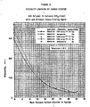
- Viscosity reduction brought about by adding supercritical carbon dioxide fluid to a viscous coatings composition is illustrated in Figure 2.
- the viscous coating composition of 65 percent polymer solution in methyl amyl ketone, which corresponds to point D in Figure 1, has a viscosity of 300 mPa ⁇ s and the solution is unsprayable.
- Adding supercritical carbon dioxide fluid to the coating composition reduces the viscosity such that a liquid mixture that contains 28 percent supercritical carbon dioxide fluid, which corresponds to point E in Figure 1, has a viscosity of less than 30 mPa ⁇ s the mixture readily forms a liquid spray by passing it through an orifice in an airless spray gun.
- the pressure is 86 bar (1250 psi) and the temperature is 50°C.
- the polymer is Acryloid TM AT-400, a product of Rohm and Haas Company, which contains 75 percent nonvolatile acrylic polymer dissolved in 25 percent methyl amyl ketone.
- the active solvent(s) suitable for the practice of this invention generally include any solvent or mixture of solvents that is miscible with the supercritical fluid and is a good solvent for the polymer system. It is recognized that some organic solvents, such as cyclohexanol, have utility as both conventional solvents and as supercritical fluid diluents. As used herein, the term "active solvent” does not include solvents in the supercritical state.
- ketones such as acetone, methyl ethyl ketone, methyl isobutyl ketone, mesityl oxide, methyl amyl ketone, cyclohexanone, and other aliphatic ketones
- esters such as methyl acetate.
- ethers such as methyl t-butyl ethers, dibutyl ether, methyl phenyl ether, and other aliphatic or alkyl aromatic ethers
- glycol ethers such as ethoxyethanol, butoxyethanol, ethoxypropanol, propoxyethanol, butoxypropanol, and other glycol ethers
- glycol ether esters such as butoxyethoxy acetate, ethyl ethoxy propionate, and other glycol ether esters
- alcohols such as methanol, ethanol, propanol, 2-propanol, butanol, amyl alcohol, and other aliphatic alcohols
- aromatic hydrocarbons such as toluene, xylene, and other aromatics or mixtures of aromatic solvents
- halocarbons such as nitroalkanes such as 2-nitropropane.
- solvents suitable for this invention must have the desired solvency characteristics as aforementioned and also the proper balance of evaporation rates so as to insure good coating formation.
- a review of the structural relationships important to the choice of solvent or solvent blend is given by Dileep et al, Industrial and Engineering Chemistry Product Research and Development 24 , 162, 1985 and Francis, A. W., Journal of Physical Chemistry 58 , 1099, 1954.
- the amount of active solvent used should be less than that required to produce a mixture of polymeric compounds and active solvent having a viscosity which will permit its application by liquid spray techniques.
- the inclusion of active solvent(s) should be diminished or minimized such that the diluent effect due to the presence of the supercritical fluid diluent is fully utilized.
- this requires that the mixture of polymeric compounds and active solvent have a viscosity of nor less than 150 mPa ⁇ s at spray temperature.
- the solvent(s) should be present in amounts ranging from 0 to 70 weight percent based upon the total weight of the polymer(s), solvent(s), and supercritical fluid diluent. Most preferably, the solvent(s) are present in amounts ranging from 5 to 50 weight percent on the same basis.
- the coating formulation employed in the process of the present invention includes polymeric compound(s), supercritical fluid diluent(s), and optionally, active solvent(s). Pigments, pigment extenders, metallic flakes, fillers, drying agents, antifoaming agents, antiskinning agents, wetting agents, ultraviolet absorbers, cross-linking agents, and other additives well known in the art may also be included in the compositions applied by the claimed process.
- a review of the use of coating additives in coating formulations is given by Lambourne, R., Editor, Paint and Surface Coatings: Theory and Practice , John Wiley & Sons, New York, 1987.
- Solvents other than the active solvents may also be used in the practice of the present invention. These solvents are typically those in which the polymeric compound(s) have only limited solubility. However, these solvents are soluble in the active solvent and therefore constitute an economically attractive route to viscosity reduction of the spray mixture. Examples of these solvents include lower hydrocarbon compounds.
- liquid spray mixture (a), (b), and optionally (c) is not necessary in the practice of the present invention. However, it is often preferred to initially mix the polymer(s) (a) and any active solvent(s) (c) used, due to the relatively high viscosities normally exhibited by many polymer components.
- the liquid mixture of (a), (b), and optionally (c) is sprayed onto a substrate to form a liquid coating thereon by passing the liquid mixture under pressure through an orifice into the environment of the substrate to form a liquid spray.
- An orifice is a hole or an opening in a wall or housing, such as in a spray tip of a spray nozzle on a spray gun, through which the liquid mixture of (a), (b), and optionally (c) flows in going from a region of higher pressure, such as inside the spray gun, into a region of lower pressure, such as the air environment outside of the spray gun and around the substrate.
- An orifice may also be a hole or an opening in the wall of a pressurized vessel, such as a tank or cylinder.
- An orifice may also be the open end of a tube or pipe or conduit through which the mixture is discharged. The open end of the tube or pipe or conduit may be constricted or partially blocked to reduce the open area.
- Spray orifices, spray tips, spray nozzles, and spray guns used for conventional airless and air-assisted airless spraying of coating formulations are suitable for spraying coating formulations with supercritical fluids, that is, for spraying the liquid mixture of (a), (b), and optionally (c).
- Spray guns, nozzles, and tips are preferred that do not have excessive flow volume between the orifice and the valve that turns the spray on and off.
- the spray guns may be automatic or hand spray.
- the spray guns, nozzles, and tips must be built to contain the spray pressure used.
- the material of construction of the orifice is not critical in the practice of the present invention, provided the material possesses necessary mechanical strength for the high spray pressure used, has sufficient abrasion resistance to resist wear from fluid flow, and is inert to chemicals with which it comes into contact.
- the orifice sizes suitable for the practice of the present invention generally range from 0.1 - 1.83 mm (0.004 to 0.072 in) diameter. Because the orifices are generally not circular, the diameters referred to are equivalent to a circular diameter. The proper selection is determined by the orifice size that will supply the desired amount of liquid coating and accomplish proper atomization for the coating. Generally smaller orifices are desired at lower viscosity and larger orifices are desired at higher viscosity. Smaller orifices give finer atomization but lower output. Larger orifices give higher output but poorer atomization. Finer atomization is preferred in the practice of the present invention. Therefore small orifice sizes from 0.1 - 0.635 mm (0.004 to 0.025 in) diameter are preferred. Orifice size from 0.18 - 0.38 mm (0.007 - 0.015 in) diameter are most preferred.
- the designs of the spray tip that contains the spray orifice and of the spray nozzle that contains the spray tip are not critical to the practice of the present invention.
- the spray tips and spray nozzles should have no protuberances near the orifice that would interfere with the spray.
- the shape of the spray is not critical to the practice of the present invention.
- the spray may be in the shape of a cone that is circular or elliptical in cross section or the spray may be in the shape of a flat fan, but the spray is not limited to these shapes.
- Sprays that are flat fans or cones that are elliptical in cross section are preferred. Wide-angle fans are most preferred.
- the distance from the orifice to the substrate is not critical to the practice of the present invention. Generally the substrate will be sprayed from a distance of 102 - 610 mm (4 - 24 in). A distance of 152 - 457 mm (6 - 18 in) is preferred. A distance of 203 - 356 mm (8 - 14 in) is most preferred.
- Devices and flow designs that promote turbulent or agitated flow in the liquid mixture prior to passing the liquid mixture under pressure through the orifice may also be used in the practice of the present invention.
- Such techniques include but are not limited to the use of pre-orifices, diffusers, turbulence plates, restrictors, flow splitters/combiners, flow impingers, screens, baffles, vanes, and other inserts, devices, and flow networks that are used in airless spray and air-assisted airless spray.
- Filtering the liquid mixture prior to flow through the orifice is desirable in the practice of the present invention in order to remove particulates that might plug the orifice. This can be done using conventional high-pressure paint filters.
- a filter may also be inserted at or in the gun and a tip screen may be inserted at the spray tip to prevent orifice plugging.
- the size of the flow passages in the filter should be smaller than the size of the orifice, preferably significantly smaller.
- the spray pressure used in the practice of the present invention is a function of the coating formulation, the supercritical fluid being used, and the viscosity of the liquid mixture.
- the minimum spray pressure is at or slightly below the critical pressure of the supercritical fluid. Generally the pressure will be below 345 bar (5000 psi). Preferably the spray pressure is above the critical pressure of the supercritical fluid and below 207 bar (3000 psi). If the supercritical fluid is supercritical carbon dioxide fluid, the preferred spray pressure is between 74 and 207 bar (1070 and 3000 psi). The most preferred spray pressure is between 83 and 172.5 bar (1200 psi and 2500 psi).
- the spray temperature used in the practice of the present invention is a function of the coating formulation, the supercritical fluid being used, and the concentration of supercritical fluid in the liquid mixture.
- the minimum spray temperature is at or slightly below the critical temperature of the supercritical fluid.
- the maximum temperature is the highest temperature at which the components of the liquid mixture are not significantly thermally degraded during the time that the liquid mixture is at that temperature.
- the spray composition is preferably heated prior to atomization.
- the minimum spray temperature is about 31°C.
- the maximum temperature is determined by the thermal stability of the components in the liquid mixture.
- the preferred spray temperature is between 35° and 90°C centigrade. The most preferred temperature is between 45° and 75°C. Generally liquid mixtures with greater amounts of supercritical carbon dioxide fluid require higher spray temperatures to counteract the greater cooling effect.
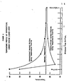
- the cooling effect of the supercritical carbon dioxide fluid on the spray temperature profile is illustrated in Figure 3.
- the spray undergoes rapid cooling while it is close to the orifice, so the temperature drops rapidly to near or below ambient temperature. If the spray cools below ambient temperature, entrainment of ambient air into the spray warms the spray to ambient or near ambient temperature before the spray reaches the substrate.
- This rapid cooling is beneficial, because less active solvent evaporates in the spray in comparison to the amount of solvent lost in conventional heated airless sprays. Therefore a greater proportion of the active solvent is retained in the coating formulation to aid leveling of the coating on the substrate.
- Conventional heated airless sprays also cool to ambient temperature before reaching the substrate, because of solvent evaporation and entrainment of ambient air.
- the spray temperature may be obtained by heating the liquid mixture before it enters the spray gun, by heating the spray gun itself, by circulating the heated liquid mixture to or through the spray gun to maintain the spray temperature, or by a combination of methods. Circulating the heated liquid mixture through the spray gun is preferred, to avoid heat loss and to maintain the desired spray temperature.
- Tubing, piping, hoses, and the spray gun are preferably insulated or heat traced to prevent heat loss.
- the environment in which the liquid spray of the present invention is conducted is not narrowly critical. However, the pressure therein must be less than that required to maintain the supercritical fluid component of the liquid spray mixture in the supercritical state.
- the present invention is conducted in air under conditions at or near atmospheric pressure.
- Other gas environments can also be used, such as air with reduced oxygen content or inert gases such as nitrogen, carbon dioxide, helium, argon, or xenon, or a mixture.
- Oxygen or oxygen enriched air is not desirable, because oxygen enhances the flammability of organic components in the spray.
- liquid spray droplets are produced which generally have an average diameter of one micron or greater. Preferably, these droplets have average diameters of from 5 to 1000 ⁇ m. More preferably, these droplets have average diameters of from 10 to 300 ⁇ m. Small spray droplets are desirable to vent the supercritical fluid from the spray droplet before impacting the substrate. Small spray droplets also give higher quality finishes.
- the present process may be used to apply coatings by the application of liquid spray to a variety of substrates.
- substrates are therefore not critical in the practice of the present invention.
- suitable substrates include but are not limited to metal, wood, glass, plastic, paper, cloth, ceramic, masonry, stone, cement, asphalt, rubber, and composite materials.
- films may be applied to substrates such that the cured films have thicknesses of from 50 - 100 ⁇ m (0.2 - 4.0 mils).
- the films Preferably, the films have thicknesses of from 12.7 - 50 ⁇ m (0.5 - 2.0 mils), while most preferably, their thicknesses range from 18 - 38 ⁇ m (0.7 to 1.5 mils).
- curing of the coating composition present upon the coated substrate may be performed at this point by conventional means, such as allowing for evaporation of the active solvent, application of heat or ultraviolet light, etc.
- the present invention may utilize compressed gas to assist formation of the liquid spray and/or to modify the shape of the liquid spray that comes from the orifice.
- the assist gas is typically compressed air at pressures from 0.345 - 5.52 bar (5 - 80 psi), with low pressures of 0.345 - 1.38 bar (5 - 20 psi) preferred, but may also be air with reduced oxygen content or inert gases such as compressed nitrogen, carbon dioxide, helium, argon, or xenon, or a mixture.
- Compressed oxygen or oxygen enriched air is not desirable, because oxygen enhances the flammability of the organic components in the spray.
- the assist gas is directed into the liquid spray as one or more high-velocity jets of gas, preferably arranged symmetrically on each side of the liquid spray to balance each other.
- the assist gas jets will preferably come from gas orifices built into the spray tip and/or nozzle.
- the assist gas may also issue from an opening in the spray tip or nozzle that is a concentric annular ring that is around and centered on the liquid orifice, to produce a hollow-cone high-velocity jet of gas that converges on the liquid spray, but this creates a larger flow of assist gas that is not as desirable.
- the concentric annular ring may be divided into segments, to reduce gas flow rate, and it may be elliptical instead of circular, to shape the spray.
- the flow rate and pressure of the assist gas are lower than those used in air spray.
- the assist gas may be heated to counteract the rapid cooling effect of the supercritical fluid diluent in the liquid spray.
- the preferred temperature of the heated assist gas ranges from 35 to 90°C.
- the most preferred temperature ranges from 45 to 75°C.
- Example illustrates the practice of the present process in a batch mode.
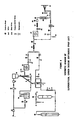
- Table 2 contains a listing of the equipment used in conducting the procedure described in the Example.
- the apparatus consisted of a circulation loop, a carbon dioxide feed system, and a side loop to measure viscosity and density.
- the circulation loop contained a pump supply tank (7), a gear pump (8) to provide circulation and maintain constant spray pressure, a static mixer (11), a cooler (12) to remove excess heat, a spray supply tank (13), an airless spray gun (14), a site glass (18), and a pressure regulator (19) to maintain constant spray pressure.
- the pressure regulator (19) was set by using compressed nitrogen (21) regulated to the desired flow pressure.
- the carbon dioxide feed system contained a carbon dioxide bulk supply cylinder (1), a refrigeration heat exchanger (2), and a carbon dioxide feed tank (3) mounted on an electronic scale (6).
- the feed and exit lines to the feed tank (3) were coiled so that the force of the tank moving on the scale did not affect the scale reading.
- the side loop contained a viscometer (24) and pyncnometer (25) for measuring the viscosity and density of the spray solution, if desired.
- the batch spray unit was filled by the following procedure.
- the unit was evacuated through the circulation loop vent (16) and a weighed amount of premixed coating concentrate was added through the feed valve (17) with the gear pump (8) circulating the material at a slow rate through the pressure regulator bypass valve (20).
- the carbon dioxide feed tank (3) was evacuated through the vent valve (5) and filled with liquid carbon dioxide from the carbon dioxide supply cylinder (1).
- the carbon dioxide was passed through a refrigeration heat exchanger (2), so that the vapor pressure in the feed tank (3) is lower than the vapor pressure in the supply tank (1).
- the desired mass of carbon dioxide was pressurized into the circulation loop by heating the carbon dioxide feed tank (3) and valving in the desired amount as read on the balance (6).
- the spray pressure was generated by filling the unit with coating concentrate and carbon dioxide to the required overall density and then heating it to the spray temperature.
- the pressure regulator (19) Prior to spraying. the pressure regulator (19) was bypassed (20) and the loop was at a uniform pressure. To prepare for spraying, the bypass (20) was closed so that the flow went through the pressure regulator (19), which was adjusted to the flow pressure.
- the spray pressure was kept constant by the gear pump (8) and the pressure regulator (19).
- the gear pump (8) pumped solution into the spray supply tank (13) from the pump supply tank (7) at a high circulation rate.
- the pressure regulator (19) discharged excess solution back into the pump supply tank (7).
- the pump supply tank (7) lost inventory and pressure, but the spray supply tank (13) was kept full and at spray pressure.
- a clear acrylic coating concentrate having a total weight of 3643 grams was prepared by mixing the following materials: 2368 grams of Rohm & Haas Acryloid TM AT-400 Resin, which contains 75% nonvolatile acrylic polymer dissolved in 25% methyl amyl ketone solvent; 740 grams of American Cyanamid Cymel TM 323 Resin, which is a cross-linking agent that contains 80% nonvolatile melamine polymer dissolved in 20% isobutanol solvent, 364 grams of methyl amyl ketone solvent; 171 grams of n butanol solvent.
- the coating concentrate contained 65.0% nonvolatile polymer solids and 35.0% volatile organic solvent.
- a liquid spray mixture having a total weight of 5059 grams was prepared by filling the spray unit with the coating concentrate and adding 1416 grams of carbon dioxide.
- the spray mixture contained 46.8% nonvolatile polymer solids, 25.2% volatile organic solvent, and 28.0% carbon dioxide.
- the overall density of the spray mixture was 1.03 g/cm3.
- the spray mixture was pressurized to a spray pressure of 82.8 bar (1200 psig) by heating it to a spray temperature of 47 C. The mixture formed a clear single-phase solution.
- Test panels (15) were mounted vertically and sprayed from a distance of 254 - 305 mm (10 - 12 in) by using a Graco Silver airless hand spray gun model #208-327 with swivel connector #204-260, in-line fluid filter #210-500g, and circulating adapter # 208-433.
- the gun contained a 0.9 mm (0.037 in) pre-orifice (fluid diffuser) turbulence promoter.
- the following spray tips were used: Graco Tip Number Orifice Diameter Fan Width Rating 305 mm (12 in) Flow Rating (in) mm (in) mm (gal/min) l/min 163-307 (0.007) 0.18 (6-8) 152-203 (0.05) 0.19 163-309 (0.009) 0.23 (6-8) 152-203 (0.08) 0.30 163-509 (0.009) 0.23 (10-12) 254-305 (0.08) 0.30 216-311 (0.011) 0.28 (6-8) 152-203 (0.12) 0.45
- the panels, held vertical, were baked at a temperature of 120°C for twenty minutes to harden the coating.
- the panels were covered by thin clear glossy coherent polymeric coatings.
- Coating thickness was measured at nine places (spaced as an array) on each panel by using a magnetic coating thickness meter (Paul N. Gardner Company Fort Lauderdale, Florida). Coating gloss was measured by using a Glossgard TM II 20-Degree Glossmeter (Gardner/Neotec Instrument Division, Pacific Scientific Company, Silver Spring, Maryland), which measures the intensity of a beam of light reflected off of the coating at an angle of twenty degrees from perpendicular. Gloss was measured at the top, center, and bottom of each panel.
- Coating distinctness of image was measured at the center of each panel by using a Distinctness of Image Meter, Model 300 (Mechanical Design and Engineering Company, Burton, Michigan), which is a viewing box in which the clarity of images reflected off of the coating and reference surfaces are compared.
- the results are given below:
- Spray tips #163-307 and #216-311 produced spray fans that were off center. Therefore, some spray material intercepted a spray tip guard on the spray nozzle.
- Example 1 The same apparatus, procedure, coating concentrate, spray mixture, and spray gun were used as in Example 1.
- the spray tip was Graco #163-309, which has an orifice diamter of 0.23 mm (0.009 in) and a fan width rating of 152 - 203 mm (6 - 8 in).
- the safety tip guard was removed from the spray nozzle.
- the spray pressure was 82.8 bar (1200 psig) and the spray temperature was 50°C.
- Test panels were sprayed to different thicknesses and baked, which produced clear polymeric coatings with the following average properties: Coating Thickness 20° Gloss Distinctness of Image Bubble Area (mil) ⁇ m (1.1) 28 83% 75% 0% (1.3) 33 90% 75% 0% (1.6) 41 88% 75% 0% (1.9) 48 82% 70% 20% (2.3) 58 76% 70% 50% (2.7) 69 54% 55% 90% (3.0) 76 13% 10% 100% The incidence of bubbles forming in the coatings increased with coating thickness. The fraction of coating area having bubbles is indicated above. The thin coatings contained no bubbles. The coatings had moderate orange peel.
- a clear acrylic coating concentrate having a total weight of 3715 grams was prepared by mixing the following materials: 2415 grams of Rohm & Haas Acryloid TM AT-400 Resin, 755 grams of American Cyanamid Cymel TM 323 Resin, 371 grams of methyl amyl ketone solvent, 174 grams of n-butanol solvent.
- the coating concentrate contained 65.0% nonvolatile polymer solids and 35.0% volatile organic solvent.
- a liquid spray mixture having a total weight of 5159 grams was prepared by filling the spray unit with the coating concentrate and adding 1444 grams of carbon dioxide.
- the spray mixture contained 46.8% nonvolatile polymer solids, 25.2% volatile organic solvent, and 28.0% carbon dioxide.
- the spray pressure was 110 bar (1600 psig) and the spray temperature was 48°C.
- the mixture was a clear single-phase solution.
- Test panels were sprayed by using the same Graco Silver airless spray gun as in Examples 1 and 2, but with a 2.3 mm (0.090 in) pre-orifice (fluid diffuser) turbulence promoter. After being baked, the panels were covered by clear polymeric coatings that had the following average properties: Tip Number Orifice Diameter Fan Width Rating Coating Thickness 20° Gloss Distinct.
- the spray gun was a Binks Airless 1 hand spray gun with circulating adapter #111-1354.
- the gun had a three-channel flow splitter/combiner that fed the flow to the spray orifice.
- the spray tips used were #9-0960, #9-0970, and #9-0980, which have an orifice diameter of 0.23 mm (0.009 in) and fan width ratings of 216, 241 and 267 mm (8.5, 9.5 and 10.5 in), respectively, which correspond to spray angles of 60, 70, and 80°C .
- the spray pressure was 110 bar (1600 psig) and the spray temperature was 50°C.
- the spray mixture was a clear single-phase solution.
- Test panels were sprayed and baked, which produced clear polymeric coatings with the following average properties: Binks Spray tip Coating Thickness 20° Gloss Distinctness of Image (mil) ⁇ m 9-0960 (1.8) 46 24% 20% 9-0970 (0.9) 23 69% 55% 9-0970 (1.1) 28 69% 40% 9-0970 (1.5) 38 67% 45% 9-0970 (1.8) 46 77% 40% 9-0970 (3.2) 81 31% 30% 9-0980 (1.6) 41 29% 20% 9-0980 (1.9) 48 28% 20%
- the spray fan was poorly formed, uneven (fingered), and fluctuated during the spray session. Coating material was deposited in uneven bands. The thick bands foamed. During a long solvent flash period, most of the bubbles dissipated, but left heavy orange peel on the surface.
- the spray gun was a Nordson A4B circulating airless hand spray gun model #152-200.
- the spray gun was connected to the Graco spray hoses by using two Nordson 4.8 mm (3/16") static'free nylon high-pressure whip hoses model #828-036.
- the gun has a two-channel flow splitter followed by a single-channel flow combiner that feeds the flow to the spray orifice.
- the spray tip was #0004/08, which has a 0.23 mm (0.009 in) orifice diameter and an 203 mm (8 in) fan width rating.
- the spray pressure was 110 bar (1600 psig) and the spray temperature was 49°C.
- the spray mixture was a clear single-phase solution.
- Test panels were sprayed and baked, which produced thin clear polymeric coatings with the following average properties: Coating Thickness 20° Gloss Distinctness of Image (mil) ⁇ m (1.0) 25 64% 55% (1.1) 28 80% 70% (1.5) 38 82% 65% (1.6) 41 78% 60%
- the spray fan had fine fingers and a concentrated jet in the center. No bubbles formed in the thin coatings. Streaks of bubbles formed in the thick coatings where coating was deposited by the concentrated jet.
- Example 5 The same apparatus, procedure, coating concentrate, spray mixture, spray gun, and spray tip were used as in Example 5.
- the spray pressure was 110 bar (1600 psig) and the spray temperature was 59°C.
- the spray mixture was a clear single-phase solution.
- Test panels were sprayed and baked, which produced polymeric coatings with the following average properties: Coating Thickness 20° Gloss Distinctness of Image (mil) ⁇ m (0.6) 15 64% 55% (0.8) 20 85% 80% (1.0) 25 85% 80% (1.2) 30 88% 85%
- the spray was finely divided, nearly uniform, and had no jetting.
- the coatings were thin, bubble free, and had good gloss and good distinctness of image.
- a clear acrylic coating concentrate having a total weight of 3279 grams was prepared by mixing the following materials: 2131 grams of Rohm & Haas Acryloid TM AT-400 Resin, 666 grams of American Cyanamid Cymel TM 323 Resin, 328 grams of methyl amyl ketone solvent, 154 grams of n-butanol solvent.
- the coating concentrate contained 65.0% nonvolatile polymer solids and 35.0% volatile organic solvent.
- a liquid spray mixture having a total weight of 4822 grams was prepared by filling the spray unit with the coating concentrate and adding 1543 grams of carbon dioxide.
- the spray mixture contained 44.2% nonvolatile polymer solids, 23.8% volatile organic solvent, and 32.0% carbon dioxide.
- the spray pressure was 110 bar (1600 psig) and the spray temperature of 58°C. A trace of fine bubbles showed that the spray mixture was at the solubility limit of carbon dioxide.
- the spray fan was uniform.
- Test panels were sprayed and baked, which produced thin clear bubble-free glossy polymeric coatings with the following average properties: Coating Thickness 20° Gloss Distinctness of Image (mil) ⁇ m (0.6) 15 26% 20% (0.9) 23 74% 60% (1.2) 30 82% 70% (1.2) 30 83% 75%
- Example 7 The same apparatus, procedure, coating concentrate, spray gun, and spray tip were used as in Example 7.
- a liquid spray mixture having a total weight of 5122 grams was prepared by filling the spray unit with the coating concentrate and adding 1843 grams of carbon dioxide.
- the spray mixture contained 41.6% nonvolatile polymer solids, 22.4% volatile organic solvent, and 36.0% carbon dioxide.
- the spray pressure was 110 bar (1600 psig) and the spray temperature was 50°C. Carbon dioxide was in excess of the solubility and produced a two-phase spray mixture.
- Test panels were sprayed and baked, which produced clear polymeric coatings with the following average properties: Coating Thickness 20° Gloss Distinctness of Image (mil) ⁇ m (0.9) 23 49% 50% (1.1) 28 80% 60% (2.3) 58 40% 35% (2.6) 66 31% 5%
- the spray was finely divided and uniform. The thin coatings were grainy in appearance and bubble free. The thick coatings were totally covered by very fine bubbles.
- a clear acrylic coating concentrate having a total weight of 3715 grams was prepared by mixing the following materials: 2786 grams of Rohm & Haas Acryloid TM AT-400 Resin, 871 grams of American Cyanamid Cymel TM 323 Resin, 58 grams of n-butanol solvent.
- the coating concentrate contained 75.0% nonvolatile polymer solids and 25.0% volatile organic solvent.
- the viscosity of the coating concentrate at a temperature of 50°C was measured as 1950 mPa ⁇ s by using a Brookfield viscometer.
- a liquid spray mixture having a total weight of 5159 grams was prepared by filling the spray unit with the coating concentrate and adding 1444 grams of carbon dioxide.
- the spray mixture contained 54.0% nonvolatile polymer solids, 18.0% volatile organic solvent, and 28.0% carbon dioxide.
- the spray pressure was 112 bar (1625 psig) and the spray temperature was 51°C.
- the viscosity of the spray mixture was measured to be 45 mPa ⁇ s by using the Ruska viscometer.
- Two test panels were sprayed and baked, which produced clear polymeric coatings with the following average properties: Coating Thickness 20° Gloss Distinctness of Image (mil) ⁇ m (1.9) 48 75% 55% (2.0) 51 77% 55%
- the coating was applied thicker than normal to aid leveling .
- the coatings were bubble free but had orange peel and a grainy appearance at thin spots.
- a white pigmented acrylic coating concentrate having a total weight of 3715.0 grams was prepared by mixing the following materials: 1182.3 grams of Du Pont white titanium dioxide pigment R902, 1445.3 grams of Rohm & Haas Acryloid TM AT-400 Resin, 451.6 grams of American Cyanamid Cymel TM 323 Resin, 290.9 grams of methyl amyl ketone, 343.2 grams of n-butanol, 1.7 grams of 10% Union Carbide silicone surfactant L5310 in xylene.
- the coating concentrate contained 70.7% nonvolatile solids and 29.3% volatile organic solvent.
- a liquid spray mixture having a total weight of 5159.0 grams was prepared by filling the spray unit with the coating concentrate and adding 1444.0 grams of carbon dioxide.
- the spray mixture contained 50.9% nonvolatile solids, 21.1% volatile organic solvent, and 28.0% carbon dioxide.
- Test panels were sprayed at different temperatures and pressures and to various thicknesses, as given below. The panels were baked at a temperature of 120°C for 20 minutes. The panels were covered by thin white glossy coherent polymeric coatings having the following average properties: The spray became more uniform and less fingered at higher spray temperature. Therefore coating gloss and distinctness of image improved at higher spray temperature. No bubbles occurred in any coating during or after spraying at any spray temperature or coating thickness used.
- solvent popping of the coating during baking was found to occur when the coating was too thick. Solvent popping occurs when the organic solvent in the coating vaporizes during baking and vents from the coating by creating a small hole in the surface. By using a higher spray temperature, thicker coatings could be applied without causing solvent popping. Heating the panels more slowly in the oven might have prevented it. No solvent popping occured in clear coatings, even for very thick coatings.
- a clear acrylic coating concentrate having a total weight of 2688 grams was prepared by mixing the following materials: 1183 grams of Rohm & Haas Acryloid TM B-66 Resin, a solid high-molecular-weight acrylic polymer that requires no cross-linking agent or baking, 1505 grams of methyl amyl ketone solvent.
- the coating concentrate contained 44.0% nonvolatile polymer solids and 56.0% volatile organic solvent.
- a liquid spray mixture having a total weight of 4800 grams was prepared by filling the spray unit with the coating concentrate and adding 2112 grams of carbon dioxide.
- the spray mixture contained 24.6% nonvolatile polymer solids, 31.4% volatile organic solvent, and 44.0% carbon dioxide.
- the spray pressure was 103 bar (1500 psig) and the spray temperature was 50°C.
- the mixture formed a clear single-phase solution.
- the viscosity of the spray mixture was measured to be approximately 11 mPa ⁇ s by using the Ruska viscometer.
- the spray gun was the Nordson A4B airless circulating hand spray gun #152-200 with spray tip #0004/08, which has a 0.23 mm (0.009 in) orifice diameter and an 203 mm (8 in) fan width rating.
- Test panels were sprayed and dried without baking.
- the clear polymeric coatings were smooth, coherent, uniform, bubble-free, and glossy; they had the following average properties: Coating Thickness 20° Gloss Distinctness of Image (mil) ⁇ m (0.60) 15.1 55% 55% (0.77) 19.6 64% 55% (0.80) 20.3 64% 55% (1.19) 30.3 72% 60%
- a clear cellulose acetate butyrate coating concentrate having a total weight of 3402 grams was prepared by mixing the following materials: 717 grams of Eastman Chemical cellulose acetate butyrate, a solid very-high-molecular-weight polymer that requires no cross-linking agent or baking, 2685 grams of methyl amyl ketone solvent.
- the coating concentrate contained 21.1% nonvolatile polymer solids and 78.9% volatile organic solvent.
- the viscosity of the coating concentrate was measured to be 960 mPa ⁇ s at room temperature and 160 mPa ⁇ s at 50°C by using a Brookfield viscometer.
- a liquid spray mixture having a total weight of 4725 grams was prepared by filling the spray unit with the coating concentrate and adding 1323 grams of carbon dioxide.
- the spray mixture contained 15.2% nonvolatile polymer solids, 56.8% volatile organic solvent, and 28.0% carbon dioxide.
- the spray pressure was 93 bar (1350 psig) and the spray temperature was 50°C. The mixture formed a clear single-phase solution.
- the spray gun used was the Nordson A4B airless circulating hand spray gun #152-200 with spray tip #0004/10, which has a 0.23 mm (0.009 in) with diameter and an 254 mm (10 in) fan width rating.
- Three test panels were sprayed and dried without baking, which produced very thin, clear, smooth, bubble free, semi-gloss, coherent polymeric coatings with average thickness of 7.6, 7.6, and 10.2 ⁇ m (0.3, 0.3 and 0.4 mil).
- a clear cellulose acetate butyrate coating concentrate having a total weight of 3578 grams was prepared by mixing the following materials: 923 grams of Eastman Chemical cellulose acetate butyrate, 2655 grams of methyl amyl ketone solvent.
- the coating concentrate contained 25.8% nonvolatile polymer solids and 74.2% volatile organic solvent.
- the viscosity of the coating concentrate was measured to be 330 mPa ⁇ s at a temperature of 50°C by using a Brookfield viscometer.
- a liquid spray mixture having a total weight of 4969 grams was prepared by filling the spray unit with the coating concentrate and adding 1391 grams of carbon dioxide.
- the spray mixture contained 18.6% nonvolatile polymer solid 53.4% volatile organic solvent, and 28.0% carbon dioxide.
- the spray pressures and temperatures are given below.
- the mixture formed a clear single-phase solution.
- Three test panels were sprayed and dried without baking, which produced thin, clear, smooth, bubble free, semi-gloss, coherent polymeric coatings with average thicknesses with average thicknesses driven above. Using less organic solvent than in Example 12 allowed thicker coatings to be applied at one application.
- a clear polystyrene coating concentrate having a total weight of 3515 grams was prepared by mixing the following materials: 945 grams of Dow polystyrene, very-high-molecular-weight polymer that requires no cross-linking agent or baking, 2570 grams of toluene solvent.
- the coating concentrate contained 26.9% nonvolatile polymer solids and 73.1% volatile organic solvent.
- the viscosity of the coating concentrate was measured to be 1950 mPa ⁇ s at a temperature of 21 C and 1070 mPa ⁇ s at a temperature of 50°C by using a Brookfield viscometer.
- a liquid spray mixture having a total weight of 4942 grams was prepared by filling the spray unit with the coating concentrate and adding 1427 grams of carbon dioxide.
- the spray mixture contained 19.1% nonvolatile polymer solids, 52.0% volatile organic solvent, and 28.9% carbon dioxide.
- the spray pressure was 100 bar (1450 psig) and the spray temperature was 48°C. The mixture formed a clear single-phase solution.
- the spray gun used was the Nordson A4B airless circulating hand spray gun #152-500 with spray tip #0006/08,which has a 0.28 mm (0.011 in) orifice diameter and an 203 mm (8 in) fan width rating.
- a test panel was sprayed and dried without baking, which produced a clear coherent polymeric coating.
- Example illustrates the practice of the present process in a continuous mode.
- Table 3 contains a listing of the equipment used in conducting the procedure described in the Example.
- the coating concentrate and carbon dioxide were pumped and proportioned by using a Graco Variable Ratio Hydra-Cat TM Proportioning Pump unit (9). It proportions two fluids together t a given volume ratio by using two piston pumps (7 and 8) that are slaved together.
- the piston rods for each pump are attached to opposite ends of a shaft that pivots up and down on a center ulcrum.
- the volume ratio is varied by sliding pump (7) along the shaft, which changes the stroke length.
- the pumps are driven on demand by an air motor (10). Pumping pressure is controlled by the air pressure that drives the air motor.
- the pumps are double-acting; they pump on upstroke and downstroke.
- the primary pump (8) was used to pump the coating concentrate. It was of standard design, having one inlet and one outlet.
- the coating concentrate was supplied to the primary pump (8) from a two-gallon pressure tank (17). After being pressurized in the pump to spray pressure, the solution was then heated in an electric heater (20) to reduce its viscosity (to aid mixing with carbon dioxide), filtered in a fluid filter (21) to remove particulates, and fed through a check valve (22) into the mix point with carbon dioxide.
- the secondary pump (7) on the proportioning pump unit (9) was used to pump the quid carbon dioxide.
- a double-acting piston pump (7) with a four-check-valve design was used because of the high vapor pressure of carbon dioxide.
- the pump has an inlet and an outlet on each side of the piston; no flow occurs through the piston.
- the proportion of carbon dioxide pumped into the spray solution is varied by moving the secondary pump (7) along the moving shaft. Bone-dry-grade liquid carbon dioxide was pumped from cylinder (1) through refrigeration heat exchanger (2) to secondary pump (7). For measuring the carbon dioxide uptake rate, the carbon dioxide was pumped from Hoke cylinder (3) through heat exchanger (2) to pump (7).
- the liquid carbon dioxide was refrigerated in heat exchanger (2) in order to lower the vapor pressure, to prevent cavitation in pump (7).
- the Hoke cylinder (3) was filled from cylinder (1). Air or gaseous carbon ioxide in the cylinder (3) was vented (5) during filling.
- the Hoke cylinder (3) was mounted on a 16-kilogram Sartorius electronic scale with 0.1-gram sensitivity so that the amount of carbon dioxide in it could be weighed. After being pressurized to spray pressure in pump (7), the liquid carbon dioxide gas fed unheated through check valve (23) to the mix point with the coating concentrate.
- the mixture was mixed in static mixer (24) and pumped on demand into a circulation loop, which circulates the mixture at spray pressure and temperature to or through the spray gun (30).
- the mixture was heated in an electric heater (25) to obtain the desired spray temperature and filtered in a fluid filter (26) to remove particulates.
- Fluid pressure regulator (28) was installed to lower the spray pressure below the pump pressure, if desired, or to help maintain a constant spray pressure.
- a Jerguson site glass (29) was used to examine the phase condition of the mixture. Circulation flow in the circulation loop was obtained through the use of gear pump (32).
- a clear acrylic coating concentrate having a total weight of 14,860 grams was prepared by mixing the following materials: 9660 grams of Rohm & Haas Acryloid TM AT-400 Resin, which contains 75% nonvolatile acrylic polymer dissolved in 25% methyl amyl ketone solvent, 3020 grams of American Cyanamid Cymel TM 323 Resin, which is a cross-linking agent that contains 80% nonvolatile melamine polymer dissolved in 20% isobutanol solvent, 1484 grams of methyl amyl ketone solvent, 696 grams of n-butanol solvent.
- the coating concentrate contained 65.0% nonvolatile polymer solids and 35.0% volatile organic solvent.
- the pressure tank (17) was filled with the concentrate and pressurized with air to 3.45 bar (50 psig).
- the coating concentrate primary pump (8) was primed by opening a drain valve on the bottom of filter (21) until air was purged from the line.
- the carbon dioxide secondary pump (7) was positioned along the pivoting shaft to give 40% of maximum piston displacement
- the refrigeration flow was adjusted to a temperature of -10 C°and circulated through the refrigeration eat exchanger (2) and the refrigeration tracing on pump (7).
- the carbon dioxide feed line and circulation loop were filled with carbon dioxide and vented through valve (34) several times to purge air from the system. Then the valves to the mixing point were closed and the carbon dioxide feed line was filled to prime pump (7).
- the carbon dioxide temperature at pump (7) was -3°C.
- the carbon dioxide bulk cylinder pressure was 58.6 bar (850 psig).
- the air pressure regulator (13) was adjusted to supply the air motor (10) with air at a pressure of 4.6 bar (67 psig) to pressurize the feed lines.
- the valves to the mix point were opened and the circulation loop filled with material. With the circulation loop return valve closed, to give plug flow around the circulation loop with no backmixing, material was drained from valve (34) until a uniform composition was obtained.
- the coating concentrate heater (20) was adjusted to give a feed temperature of 37°C.
- the circulation heater (25) was adjusted to give the spray temperature.
- the circulation loop return valve was opened and the spray mixture was circulated at a high rate by adjusting the gear pump (32) to a rate of 35 revolutions per minute.
- the carbon dioxide content of the spray mixture was measured by measuring the carbon dioxide uptake rate from Hoke cylinder (3) and the coating concentrate uptake rate from pressure tank (17) while spraying through the spray gun. Then the carbon dioxide feed was switched back to supply cylinder (1).
- the spray gun (30) was a Nordson A4B circulating airless hand spray gun model #152-200.
- the spray gun was connected to the Graco spray hoses by using two Nordson 4.8 mm (3/16 in) static-free nylon high-pressure whip hoses model #828-036.
- the spray tip was #0004/08, which has a 0.23 mm (0.009 in) orifice diameter and an 203 mm (8 in) fan width rating at a distance of 254 mm (10 in) from the orifice.
- the liquid spray mixture contained 46.9% nonvolatile polymer solids, 25.3% volatile organic solvent, and 27.9% carbon dioxide.
- the spray pressure was 107 bar (1550 psig) and the spray temperature was 60°C.
- the spray mixture was a clear single-phase solution.
- Test panels (31) were mounted vertically, hand sprayed, and baked in an oven at a temperature of 120°C for 20 minutes. The panels were covered by thin clear glossy coherent polymeric coatings. Gloss and distinctness of image increased with coating thickness.
- the coatings were bubble free and had the following average properties: Coating Thickness 20° Gloss Distinctness of Image (mil) ⁇ m (0.74) 19 68% 60% (1.00) 25 74% 65% (1.03) 26 87% 75% (1.12) 28 87% 80% (1.19) 30 85% 80% (1.19) 30 87% 80% (1.25) 32 90% 85% (1.34) 34 88% 85%
- Example 15 The same apparatus, procedure, coating concentrate, spray mixture, spray pressure, spray temperature, and spray gun were used as in Example 15.
- the spray tip was Nordson #0003/08, which has a 0.18 mm (0.007 in) orifice diameter and an 203 mm (8 in) fan width rating.
- Test panels were sprayed and baked, which produced thin clear glossy coherent polymeric coatings. Gloss and distinctness of image increased with coating thickness.
- the coatings were bubble free and had the following average properties: Coating Thickness 20° Gloss Distinctness of Image (mil) ⁇ m (0.48) 12 35% 40% (0.58) 15 46% 55% (0.75) 19 70% 60% (0.81) 20.6 68% 65% (0.84) 21.3 68% 60% (0.86) 21.8 74% 60% (0.94) 23.9 84% 75% (1.20) 30.5 86% 75% (1.31) 33.3 89% 80% (1.36) 34.5 89% 80% (1.71) 43.4 90% 80%
- the carbon dioxide pump was positioned to give 42% of maximum piston displacement.
- the spray mixture contained 46.1% nonvolatile polymer solids, 24.8% volatile organic solvent, and 29.1% carbon dioxide.
- the spray tip was Nordson #0004/08, which has a 0.23 mm (0.009 in) orifice diameter and an 203 mm (8 in) fan width rating.
- Test panels were sprayed at the spray temperatures and pressures given below, then baked.
- the carbon dioxide content was near the solubility limit, because an increase in pressure changed the spray mixture from two phases to one phase.
- the polymeric coatings were thin, clear, glossy, coherent, and bubble free. They had the following average properties: Spray Temperature Spray Pressure Coating Thickness 20° Gloss Distinctness of Image No.
- the carbon dioxide pump was positioned to give 43% of maximum piston displacement.
- the liquid spray mixture contained 47.3% nonvolatile polymer solids, 25.4% volatile organic solvent, and 27.3% carbon dioxide.
- the spray mixture was a clear single phase solution.
- the spray tip was Nordson #0004/08, which has a 0.23 mm (0.009 in) orifice diameter and an 203 mm (8 in) fan width rating.
- the spray pressure was 107 bar (1550 psig) and the spray temperature was 59°C. Test panels were sprayed and baked. The polymeric coatings were thin, clear, had high gloss and high distinctness of image, and were bubble free.
- Example 18 The same apparatus, procedure, coating concentrate, and spray gun were used as in Example 18.
- the carbon dioxide pump was positioned to give 46% of maximum piston displacement.
- the liquid spray mixture contained 45.8% nonvolatile polymer solids, 24.7% volatile organic solvent, and 29.5% carbon dioxide.
- the spray mixture gas near the carbon dioxide solubility limit, because gas bubbles were present.
- the spray tip was Nordson #0004/08, which has a .009-inch orifice diameter and an 203 mm (8 in) fan width rating.
- the spray pressure was 107 bar (1550 psig) and the spray temperature was 59°C. Test panels were sprayed and baked. The polymeric coatings were thin and clear, had high gloss and high distinctness of image, and were bubble free.
- the carbon dioxide pump was positioned to give 60% of maximum piston displacement.
- the spray mixture contained 45.2% nonvolatile polymer solids, 24.3% volatile organic solvent, and 30.5% carbon dioxide.
- the spray mixture was a single-phase solution.
- the spray tip was Nordson #0004/08, which has a 0.23 mm (0.009 in) orifice diameter and an 203 mm (8 in) fan width rating.
- Test panels were sprayed at the spray temperatures and pressures given below, then baked. The polymeric coatings were thin, clear, glossy, coherent, and bubble free.
- Example 20 The same apparatus, procedure, coating concentrate, spray mixture, spray gun, spray tip, and spray temperature were used as in Example 20.
- the spray pressure was 90 bar (1300 psi).
- the spray mixture was above the solubility limit and contained gas bubbles.
- Two panels were sprayed and baked.
- the polymeric coatings were covered by individual tiny bubbles where the coating was thickest, which produced a rough surface at those locations.
- the coatings had the following average properties. Spray Temperature Spray Pressure Coating Thickness 20° Gloss °C (psi) bar (mil) ⁇ m 61 (1300) 90 (1.78) 45.2 62% 62 (1300) 90 (1.81) 46.0 56%
- Example 20 The same apparatus, procedure, coating concentrate, spray mixture, and spray gun were used as in Example 20.
- the spray pressure was 1550 psi and the spray temperature was 55°C.
- the spray tip was Nordson #0003/08, which has a 0.18 mm (0.007 in) orifice diameter and an 203 mm (8 in) fan width rating.
- Test panels were sprayed and baked.
- the polymeric coatings were thin and clear, had high gloss and good distinctness of image, and were bubble free. They had the following average properties: Coating Thickness 20° Gloss Distinctness of Image (mil) ⁇ m (0.85) 21.6 86% 70% (1.09) 27.7 90% 80% (1.26) 32.0 93% 80% (1.49) 37.8 92% 80% (1.57) 39.9 94% 85%
- a blue metallic acrylic enamel coating concentrate was prepared by mixing the following materials: two gallons of Du Pont Centari TM Acrylic Enamel B8292A Medium Blue Metallic Auto Refinish Paint, 736 grams of ethyl 3-ethoxypropionate, 240 grams of butyl CELLOSOLVE TM acetate, 8 pumps of Auto Fisheye eliminator. This paint is normally reduced before usage with thinner (Du Pont 8034S Acrylic Enamel Reducer) in the amount of adding 3.7 l (1 gallon) of thinner to 7.4 l (2 gallons) of paint. But no Acrylic Enamel Reducer was used.
- the coating concentrate contained 2.7 l (three quarters of a gallon) less volatile organic solvent than normally reduced paint.
- the carbon dioxide pump was positioned to give 45% of maximum piston displacement.
- the refrigeration heat exchanger and refrigeration tracing were used, which produced a carbon dioxide temperature of -5°C in the pump.
- the spray mixture contained 30.8% carbon dioxide.
- the carbon dioxide was fully soluble in the paint.
- the spray gun used was the Nordson A4B circulating airless hand spray gun model #152-200.
- the spray tip was #0003/08, which has a 0.18 mm (0.007 in) orifice diameter and an 203 mm (8 in) fan width rating at a distance of 254 mm (10 in) from the orifice.
- the spray temperature was 60°C and the spray pressure was 131-138 bar (1900 or 2000 psig).
- Test panels were hand sprayed, flashed for a few minutes, and baked in an oven at a temperature of 60°C for one hour.
- the polymeric coatings were uniform in gloss, color, and metallic appearance. They were bubble free. The metallic particles were properly and uniformly laid down and oriented to reflect light. Coating thickness was measured at nine places (spaced as an array); 20-degree and 60-degree gloss were measured at the top, center, and bottom; and distinctness of image was measured at the center of each panel.
- the average properties of the coatings are given below: Spray Temperature Spray Pressure Coating Thickness 20° Gloss 60° Gloss Distinct.
- Example 23 The same apparatus, procedure, and spray gun were used as in Example 23.
- the blue metallic acrylic enamel coating concentrate was two gallons of Du Pont Centari TM Acrylic Enamel B8292A Medium Blue Metallic Auto Refinish Paint. The paint was unreduced; no thinner or any other organic solvent was added.
- the spray tip was Nordson #0004/08, which has a 0.23 mm (0.009 in) orifice and an 203 mm (8 in) fan width rating.
- the carbon dioxide pump was positioned to give 35% of maximum piston displacement.
- the spray mixture contained 24.6% carbon dioxide.
- the carbon dioxide was fully soluble in the paint.
- the spray temperature was 41 or 50°C and the spray pressure was 107 bar (1550 psi). Test panels were hand sprayed, flashed for a few minutes, and baked in an oven at temperature of 60°C for one hour.
- the coatings had the following average properties: Spray Temperature Spray Pressure Coating Thickness 20° Gloss 60° Gloss Distinct. of Image °C (psi) bar (mil) ⁇ m 41 (1550) 107 (1.14) 28.9 56% 86% 55% 41 (1550) 107 (1.54) 39.1 33% 63% 30% 50 (1550) 107 (1.37) 34.8 10% 41% 5% 50 (1550) 107 (1.81) 46.0 4% 20% 0% 50 (1550) 107 (2.09) 53.1 4% 18% 0% 50 (1550) 107 (3.81) 96.8 1% 4% 0% The coatings were very poor, having little or no gloss, because the paint was held mostly in a matrix of fine bubbles, which gave the coatings a sintered look. where there were no bubbles, the coating was very mottled.
- a blue metallic acrylic enamel coating concentrate having a total weight of 5638 grams was prepared 1) by distilling 5638 grams of Du Pont Centari TM Acrylic Enamel B8292A Medium Blue Metallic Auto Refinish Paint to remove 1061 grams of solvent with low boiling points and 2) adding 1061 grams of solvent with high boiling points: 836 grams of ethyl 3-ethyoxyproprionate, 225 grams of butyl CELLOSOLVE TM acetate.
- the coating concentrate had the same volatile organic solvent content as the original unreduced paint. No thinner (Du Pont 8034S Acrylic Enamel Reducer) was used. Therefore 3.7 l (1 gallon) of volatile organic solvent was eliminated for each 7.4 l (2 gallons) of unreduced paint.
- the paint was distilled in a 3.7 l (1 gallon) wiped film evaporator at a pressure of 10 mbar (8 mm Hg) and a temperature of 31°C.
- the spray mixture contained 30.8% carbon dioxide, the same as in Example 23.
- the carbon dioxide was fully soluble in the paint.
- the spray gun used was the Nordson A4B circulating airless hand spray gun model #152-200.
- the spray tip was #0003/08, which has a 0.18 mm (0.007 in) orifice diameter and an 203 mm (8 in) fan width rating.
- the spray temperature was 60°C and the spray pressure was 103.5, 117 or 138 bar (1500, 1700 or 2000 psig).Test panels were sprayed, flashed, and baked.
- the polymeric coatings were uniform in gloss, color, and metallic appearance. They were bubble free. The metallic particles were properly and uniformly laid down and oriented to reflect light.
- the coatings had the following average properties: Spray Temperature Spray Pressure Coating Thickness 20° Gloss 60° Gloss Distinct. of Image °C (psi) bar (mil) ⁇ m 60 (1500) 103.5 (0.78) 19.8 58% 87% 55% 60 (1500) 103.5 (0.79) 20.1 50% 85% 55% 60 (1500) 103.5 (0.82) 20.8 56% 87% 55% 60 (1500) 103.5 (0.89) 22.6 58% 87% 60% 60 (1500) 103.5 (0.91) 23.1 60% 87% 60% 60 (1700) 117 (0.78) 19.8 56% 86% 55% 60 (1700) 117 (0.79) 20.1 54% 86% 55% 60 (1700) 117 (0.84) 21.3 57% 87% 55% 60 (2000) 138 (0.79) 20.1 46% 81% 50% 60 (2000) 138 (0.79) 20.1 51% 85% 55% 60 (2000) 138 (0.93) 23.6 58% 87% 60% 60 (2000) 138 (0.94) 23.9 58% 87% 55% 60 (2000) 138 (1.02) 25.
- Example 25 The same apparatus, procedure, coating concentrate, spray mixture, and spray gun were used as in Example 25.
- the spray tip was Nordson #0004/08, which has a 0.23 mm (0.009 in) orifice diameter and an 203 mm (8 in) fan width rating.
- the spray temperature was 60°C and the spray pressure was 103.5, 121, or 138 bar (1500, 1750, or 2000 psig).
- Test panels were sprayed, flashed, and baked.
- the polymeric coatings obtained were uniform in gloss, color, and metallic appearance. They were bubble free.
- the metallic particles were properly and uniformly laid down and oriented to reflect light.
- the coatings had the following average properties: Spray Temperature Spray Pressure Coating Thickness 20° Gloss 60° Gloss Distinct.
- paint reduced with thinner was prepared by adding Du Pont 8034S Acrylic Enamel Reducer to the Du Pont Centari TM Metallic Paint in the proportion of one gallon of thinner to two gallons of paint.
- Test panels were sprayed by using a conventional air spray gun. The properties of the coatings are driven above. The metallic appearance of the supercritical carbon dioxide sprayed coatings was more uniform than that of the air sprayed coatings.
- Example 23 The same apparatus, pr ocedure, coating concentrate, and spray gun were used as in Example 23.
- the carbon dioxide pump was positioned to give 50% of maximum piston displacement
- the spray mixture contained 33.0% carbon dioxide.
- the carbon dioxide was fully soluble.
- the spray tip was Nordson #0003/08, which has a 0.18 mm (0.007 in) orifice diameter and an 203 mm (8 in) fan width rating.
- the spray temperature was 50°C and the spray pressure was 103.5 bar (1500 psig).
- a test panel was sprayed, flashed, and baked.
- the polymeric coating was uniform in gloss, color, and metallic appearance. It was bubble free. Average coating properties are given below: Spray Temperature Spray Pressure Coating Thickness 20° Gloss 60° Gloss Distinct. of Image °C (psi) bar (mil) ⁇ m 50 (1500) 103.5 (1.19) 30.2 65% 86% 70%
- Example 27 The same apparatus, procedure, coating concentrate, and spray mixture were used as in Example 27.
- the spray gun used was a Binks Airless 1 hand spray gun with circulating adapter #111-1354 and spray tip #9-970, which has a 0.23mm(0.009 in) orifice diameter and a 241 mm (9.5 in) fan width rating.
- the spray temperature was 50°C and the spray pressure was 103.5 bar or 138 bar (1500 or 2000 psig).
- Test panels were sprayed, flashed, and baked. For thicker coatings, although the gloss and distinctness of image are higher, the metallic laydown is less uniform and slightly mottled. Average coating properties are given below: Spray Temperature Spray Pressure Coating Thickness 20° Gloss 60° Gloss Distinct.
- Example 27 The same apparatus, procedure, coating concentrate, and spray mixture were used as in Example 27.
- the spray gun used was a Graco Silver airless hand spray gun model #208-327 with circulating adapter #208-433.
- the gun contained a 0.9 mm (0.037 in) pre-orifice (fluid diffuser) turbulence promoter.
- the spray tip was #163-409, which has a 0.23 mm (0.009 in) orifice diameter and a fan width rating of 203-254 mm (8-10 in).
- the spray temperature was 50°C and the spray pressure was 103.5 bar (1500 psig).
- Test panels were sprayed, flashed, and baked. The metallic laydown was uneven and the coatings had a mottled appearance. Average coating properties are given below: Spray Temperature Spray Pressure Coating Thickness 20° Gloss 60° Gloss Distinct. of Image °C (psi) bar (mil) ⁇ m 50 (1500) 103.5 (0.89) 22.6 69% 89% 65% 50 (1500) 103.5 (1.25) 31.7 77% 99% 75%
Abstract
Description
- This invention relates in general to a process and apparatus for coating substrates. More particularly, this invention is directed to a process and apparatus for coating substrates by a liquid spray in which 1) supercritical fluid, such as supercritical carbon dioxide fluid, is used as a viscosity reduction diluent for coating formulations and 2) the mixture of supercritical fluid and coating formulation is passed under pressure through an orifice into the environment of the substrate to form the liquid spray.
- Coating formulations are commonly applied to a substrate by passing the coating formulations under pressure through an orifice into air in order to form a liquid spray, which impacts the substrate and forms a liquid coating. In the coatings industry, three types of orifice sprays are commonly used; namely, air spray, airless spray, and air-assisted airless spray.
- Air spray uses compressed air to break up the liquid coating formulation into droplets and to propel the droplets to the substrate. The most common type of air nozzle mixes the coating formulation and high-velocity air outside of the nozzle to cause atomization. Auxiliary air streams are used to modify the shape of the spray. The coating formulation flows through the liquid orifice in the spray nozzle with relatively little pressure drop. Siphon or pressure feed, usually at pressures less than 18 psi, are used, depending upon the viscosity and quantity of coating formulation to be sprayed.
- Airless spray uses a high pressure drop across the orifice to propel the coating formulation through the orifice at high velocity. Upon exiting the orifice, the high-velocity liquid breaks up into droplets and disperses into the air to form a liquid spray. Sufficient momentum remains after atomization to carry the droplets to the substrate. The spray tip is contoured to modify the shape of the liquid spray, which is usually a round or elliptical cone or a flat fan. Turbulence promoters are sometimes inserted into the spray nozzle to aid atomization. Spray pressures typically range from 43 to 345 bar (700 to 5000 psi). The pressures required increases with fluid viscosity.
- Air-assisted airless spray combines features of air spray and airless spray. It uses both compressed air and high pressure drop across the orifice to atomize the coating formulation and to shape the liquid spray, typically under milder conditions than each type of atomization is generated by itself. Generally the compressed air pressure and the air flow rate are lower than for air spray. Generally the liquid pressure drop is lower than for airless spray, but higher than for air spray. Liquid spray pressures typically range from 13.8 to 55.2 bar (200 to 800 psi). The pressure required increases with fluid viscosity.
- Air spray, airless spray, and air-assisted airless spray can also be used with the liquid coating formulation heated or with the air heated or with both heated. Heating reduces the viscosity of the liquid coating formulation and aids atomization.
- U. S. - A - 3,556,411; 3,647,147; 3,659,787; 3,754,710; 4,097,000; and 4,346,849 disclose spray nozzles and tips for use in airless spray, including designs and methods of manufacture and methods of promoting turbulence in the atomizing fluid. U. S. - A - 3,907,202 and 4,055,300 disclose spray nozzles for use in air-assisted airless spray. None of these patents uses supercritical fluids as diluents to spray coating formulations.
- More information about orifice sprays such as air spray, airless spray, and air-assisted airless spray and about heated sprays can be obtained from the general literature of the coating industry and from technical bulletins issued by spray equipment manufacturers, such as the following references:
- 1. Martens, C. R., Editor. 1974. Technology of Paints, Varnishes and Lacquers.
Chapter 36. Application. Robert E. Krieger Publishing Company, Huntington, New York. - 2. Fair, James. 1983. Sprays. Pages 466-483 in Grayson, M., Editor. Kirk-Othmer Encyclopedia of Chemical Technology. Third Edition.
Volume 21. Wiley-Interscience, New York. - 3. Zinc, S. C. 1979. Coating Processes. Pages 386-426 in Grayson, M., Editor. Kirk-Othmer Encyclopedia of Chemical Technology. Third Edition.
Volume 6. Wiley-Interscience, New York. - 4. Long, G. E. 1978 (March 13). Spraying Theory and Practice. Chemical Engineering: 73-77.
- 5. Technical Bulletin. Air Spray Manual. TD10-2R. Binks Manufacturing Company, Franklin Park, Illinois.
- 6. Technical Bulletin. Compressed Air Spray Gun Principles. TD10-1R-4. Binks Manufacturing Company, Franklin Park, Illinois.
- 7. Technical Bulletin. Airless Spray Manual. TD11-2R. Binks Manufacturing Company, Franklin Park, Illinois.
- 8. Technical Bulletin. Airless Spraying. TD11-1R-2. Binks Manufacturing Company, Franklin Park, Illinois.
- 9. Technical Bulletin. Hot Spraying. TD42-1R-2. Binks Manufacturing Company, Franklin Park, Illinois.
- 10. Technical bulletin on air-assisted airless spray painting system. Kremlin, Incorporated, Addison, Illinois.
- Prior to the present invention, the liquid spray application of coatings, such as lacquers, enamels, and varnishes, by the spray methods discussed above was effected solely through the use of organic solvents as viscosity reduction diluents. However, because of increased environmental concern, efforts have been directed to reducing the pollution resulting from painting and finishing operations. For this reason there is great need for new liquid spray technology for application of coatings that diminishes the emission of organic solvent vapors.
- U. S. - A - 4,582,731 discloses a method and apparatus for the deposition of thin films and the formation of powder coatings through the molecular spray of solutes dissolved in organic and supercritical fluid solvents. The molecular sprays disclosed in the Smith patent are composed of droplets having diameters of about 3 nm . These droplets are more than 10⁶ to 10⁹ less massive than the droplets formed in conventional application methods that Smith refers to as "liquid spray" applications. Furthermore, the orifice used to produce the molecular sprays is typically in the 1 to 4 µm diameter size range. These orifice sizes are 10³ to 10⁵ times smaller in area than orifices used in conventional "liquid spray" apparatus. This disclosed method of depositing thin films seeks to minimize, and preferably eliminate, the presence of solvent within the film deposited upon a substrate. This result is preferably accomplished through the maintenance of reduced pressure in the spray environment. However, the maintenance of reduced pressures is not feasible for most commercial coating applications. Furthermore, the spray method disclosed by Smith utilizes very high solvent-to-solute ratios, thereby requiring undesirably high solvent usage and requiring prohibitively long application times in order to achieve coatings having sufficient thicknesses to impart the desired durability of the coating.
- U. S. Patent Application Serial No. 133068, filed 12/21/87, (Hoy et al) discloses a process and apparatus for the liquid spray application of coatings to a substrate wherein the use of environmentally undesirable organic diluents is minimized. The process of the invention comprises:
- (1) forming a liquid mixture in a closed system, said liquid mixture comprising:
- (a) at least one polymeric compound capable of forming a coating on a substrate; and
- (b) at least one supercritical fluid, in at least an amount which when added to (a) is sufficient to render the viscosity of said mixture of (a) and (b) to a point suitable for spray applications;
- (2) spraying said liquid mixture onto a substrate to form a liquid coating thereon. The invention is also directed to a liquid spray process as described immediately above to which at least one active organic solvent (c) is admixed with (a) and (b), prior to the liquid spray application of the resulting mixture to a substrate. The preferred supercritical fluid is supercritical carbon dioxide fluid. The apparatus of the invention comprises an apparatus in which the mixture of the components of the liquid spray mixture can be blended and sprayed onto an appropriate substrate. Said apparatus is comprised of, in combination:
- (1) means for supplying at least one polymeric compound capable of forming a continuous, adherent coating;
- (2) means for supplying at least one active organic solvent;
- (3) means for supplying supercritical carbon dioxide fluid;
- (4) means for forming a liquid mixture of components supplied from (1)-(3);
- (5) means for spraying said liquid mixture onto a substrate.
- Supercritical carbon dioxide fluid is an environmentally safe, non-polluting diluent that allows utilization of the best aspects of organic solvent borne coatings applications and performance while reducing the environmental concerns to an acceptable level. It allows the requirements of shop-applied and field-applied liquid spray coatings as well as factory-applied finishes to be met and still be in compliance with environmental regulations.
- Clearly what is needed is a liquid spray method of coating substrates that can be applied to using supercritical fluids, such as supercritical carbon dioxide fluid, as diluents to reduce coating formulations to spray viscosity. Such a method should utilize the properties of the supercritical fluid, should be compatible with existing spray technology and practice, and should be environmentally acceptable.
- Prior to the present invention, however, it was unknown how a high concentration of highly volatile supercritical fluid, such as supercritical carbon dioxide fluid, would affect formation of a polymeric liquid spray. A spray mixture undergoes a large and rapid drop in pressure as it goes through the orifice. Accordingly, it was theorized that the supercritical spray mixture would produce a foam like shaving cream instead of a spray, because nucleation to form gas bubbles would be so rapid and intense. Alternatively, it was expected that the spray mixture would produce a mist or fog of microdroplets instead of a spray, because atomization would be so intense. Another likely anticipated result was that the spray mixture would produce a spray of bubbles instead of droplets. Furthermore, even if a spray were formed, it would have been expected that sudden and intense cooling that accompanies rapid depressurization and expansion of a supercritical fluid would cause the liquid droplets to freeze solid. For example, it is commonly known that the spray from carbon dioxide fire extinguishers produces solid dry ice particles.
- In the event that formation of a liquid spray were achieved, it was further considered unlikely that the spray could be used to produce quality coherent polymeric coatings on a substrate. It would be surmised that the liquid droplets would be so small or have so little momentum that they could not be deposited well onto the substrate. It was expected that foaming droplets or supercritical fluid dissolved in the coating would produce a layer of foam on the substrate or a coating full of bubbles when these characteristics were not desired in the coating. The liquid coating droplets that are deposited onto the substrate would have a much higher viscosity than the material that was sprayed, because they would have lost most of the supercritical fluid diluent and they would be at a lower temperature. Furthermore, the coating material would contain less volatile organic solvent than normal. Therefore, it was expected that higher viscosity would prevent or hinder coalescence of the deposited droplets to form a coherent liquid coating; that it would reduce how much the droplets spread out on the substrate, so that thin coatings could not be produced; and that it would reduce the surface flow that produces a smooth coating. It was further expected that moisture would condense onto the droplets and harm the coating, because the spray would be cooled below the dew point.
- Surprisingly, however, it has been discovered that liquid sprays can be formed by using supercritical fluids as viscosity reduction diluents and that such sprays can be used to deposit quality coherent polymeric coatings onto substrates.
- It is accordingly an object of the present invention to demonstrate the use of orifice sprays, such as airless spray and air-assisted airless spray, to apply liquid coatings to substrates by liquid sprays in which supercritical fluids, such as supercritical carbon dioxide fluid, are used as diluents in highly viscous organic solvent borne and/or highly viscous non-aqueous dispersions coatings compositions to dilute these compositions to application viscosity.
- A further object of the invention is to demonstrate that he method is generally applicable to all organic solvent borne coatings systems.
- In its broad aspect, this invention is directed to a process and apparatus for the liquid spray application of coatings to a substrate wherein the use of environmentally undesirable organic diluents and other volatile organic compounds is diminished. The process of the invention comprises:
- (1) forming a liquid mixture in a closed system, said liquid mixture comprising:
- (a) at least one polymeric component capable of forming a coating on a substrate; and
- (b) a solvent component containing at least one supercritical fluid, in at least an amount which when added to (a) is sufficient to render the viscosity of said mixture to a point suitable for spray application;
- (2) spraying said liquid mixture onto a substrate to form a liquid coating thereon by passing the mixture under pressure through an orifice into the environment of the substrate to form a liquid spray.
- The invention is also directed to a liquid spray process as described immediately above to which at least one active organic solvent (c) is admixed with (a) and (b), prior to the liquid spray application of the resulting mixture to a substrate.
- The invention is also directed to a liquid spray process as described above to which pigments, pigment extenders, metallic flakes, fillers, drying agents, antifoaming agents, antiskinning agents, wetting agents, ultraviolet absorbers, cross-linking agents, and other additives well known in the art are admixed with (a) and (b) and optionally (c), prior to the liquid spray application of the resulting mixture to a substrate.
- The invention is also directed to a liquid spray process as described above to which turbulent or agitated flow is promoted in the liquid mixture, prior to passing the liquid mixture under pressure through the orifice, to aid atomization.
- The invention is also directed to a liquid spray process as described above to which compressed gas, such as compressed air or compressed carbon dioxide, is used to assist formation and atomization of the liquid spray and to modify the shape of the liquid spray.
- The invention is also directed to a liquid spray process as described above to which the liquid mixture is heated or the compressed assist gas is heated or both are heated to prevent adverse effect caused by rapid cooling when the liquid mixture is sprayed.
- The invention is also directed to an apparatus in which the mixture of the components of the liquid spray can be blended and sprayed onto an appropriate substrate.
- A more detailed understanding of the invention will be had by reference to the drawings wherein:
- Figure 1 is a phase diagram of supercritical carbon dioxide fluid spray coating.
- Figure 2 is a graph illustrating the viscosity versus composition relationship for 65 percent viscous polymer solution in methyl amyl ketone.
- Figure 3 is a graph illustrating the liquid spray temperature profiles for supercritical carbon dioxide fluid spray coating and for conventional heated airless spray coating.
- Figure 4 is a schematic diagram of a batch spray apparatus that can be used in the practice of the present invention.
- Figure 5 is a schematic diagram of a continuous spray apparatus that can be used in the practice of the present invention.
- It has been found that by using the process and apparatus of the present invention, coatings can be applied to a wide variety of substrates in a manner that poses a reduced environmental hazard. Consequently, the use of organic diluents as vehicles for coating formulations can be greatly reduced by utilizing supercritical fluids, such as supercritical carbon dioxide fluid, therewith.
- Because of its importance to the claimed process, a brief discussion of relevant supercritical fluid phenomena is warranted.
- At high pressures above the critical point, the resulting supercritical fluid, or "dense gas", will attain densities approaching those of a liquid and will assume some of the properties of a liquid. These properties are dependent upon the fluid composition, temperature, and pressure.
- The compressibility of supercritical fluids is great just above the critical temperature where small changes in pressure result in large changes in the density of the supercritical fluid. The "liquid-like" behavior of a supercritical fluid at higher pressures results in greatly enhanced solubilizing capabilities compared to those of the "subcritical" compound, with higher diffusion coefficients and an extended useful temperature range compared to liquids. Compounds of high molecular weight can often be dissolved in the supercritical fluid at relatively low temperatures.
- An interesting phenomenon associated with supercritical fluids is the occurrence of a "threshold pressure" for solubility of a high molecular weight solute. As the pressure is increased, the solubility of the solute will often increase by many orders of magnitude with only a small pressure increase.
- Near-supercritical liquids also demonstrate solubility characteristics and other pertinent properties similar to those of supercritical fluids. The solute may be a liquid at the supercritical temperatures, even though it is a solid at lower temperatures. In addition, it has been demonstrated that fluid "modifiers" can often alter supercritical fluid properties significantly, even in relatively low concentrations, greatly increasing solubility for some solutes. These variations are considered to be within the concept of a supercritical fluid as used in the context of this invention. Therefore, as used herein, the phrase "supercritical fluid" denotes a compound above, at, or slightly below the critical temperature and pressure of that compound.
- Examples of compounds that are known to have utility as supercritical fluids are given in Table 1.
TABLE 1 EXAMPLES OF SUPERCRITICAL SOLVENTS Compound Boiling Point °C Critical Temperature °C Critical Pressure bar Critical Density g/ml Carbon Dioxide -78.5 31.3 72.9 0.448 Ammonia -33.35 132.4 112.5 0.235 Water 100.0 374.15 218.3 0.315 Nitrous Oxide -88.56 36.5 71.7 0.45 Xenon -108.2 16.6 57.6 0.118 Krypton -153.2 -63.8 54.3 0.091 Methane -164.0 -82.1 45.8 0.2 Ethane -88.63 32.28 48.1 0.203 Ethylene -103.7 9.21 49.7 0.218 Propane -42.1 96.67 41.9 0.217 Pentane 36.1 196.6 33.3 0.232 Methanol 64.7 240.5 78.9 0.272 Ethanol 78.5 243.0 63.0 0.276 Isopropanol 82.5 235.3 47.0 0.273 Isobutanol 108.0 275.0 42.4 0.272 Chlorotrifluoromethane -31.2 28.0 38.7 0.579 Monofluoromethane -78.4 44.6 58.0 0.3 Cyclohexanol 155.65 356.0 38.0 0.273 - The utility of any of the above-mentioned compounds as supercritical fluids in the practice of the present invention will depend upon the polymeric compound(s) and active solvent(s) used, because the spray temperature should not exceed the temperature at which significant thermal degradation of any component of the liquid spray mixture occurs.
- Supercritical carbon dioxide fluid and supercritical nitrous oxide fluid are the preferred supercritical fluids in the practice of the present invention due to their low supercritical temperature, low toxicity, nonflammability, and much lower cost than xenon or krypton. Supercritical carbon dioxide fluid is the most preferred supercritical fluid because it has low cost, is readily available, and is highly acceptable environmentally. However, use of any of the aforementioned supercritical fluids and mixtures thereof are to be considered within the scope of the present invention.
- The solvency of supercritical carbon dioxide fluid is like that of a lower aliphatic hydrocarbon (e.g. butane, pentane, or hexane) and, as a result, one can consider supercritical carbon dioxide fluid as a replacement for the hydrocarbon diluent portion of a conventional solvent borne coating formulation. Moreover, while lower aliphatic hydrocarbons are much too volatile for use in conventional coatings formulations because of the inherent explosive and fire hazard they present, carbon dioxide is non-flammable, non-toxic, and environmentally acceptable. Safety benefits therefore also result from its use in the claimed process.
- The polymeric components suitable for use in this invention as coating materials are any of the polymers known to those skilled in the coatings art. Again, the only limitation of their use in the present invention is their degradation at the temperatures or pressures involved with their admixture with the supercritical fluid. They may be thermoplastic or thermosetting materials. They may be crosslinkable film forming systems. The polymeric components include vinyl, acrylic, styrenic, and interpolymers of the base vinyl, acrylic, and styrenic monomers; polyesters, oil-free alkyds, alkyds, and the like; polyurethanes, two package polyurethanes, oil-modified polyurethanes, moisture-curing polyurethanes and thermoplastic urethanes systems; epoxy systems; phenolic systems; cellulosic esters such as acetate butyrate, acetate propionate, and nitrocellulose; amino resins such as urea formaldehyde, melamine formaldehyde, and other aminoplast polymers and resins materials; natural gums and resins; and enamels, varnishes, and lacquers. Also included are mixtures of the above coating materials commonly used and known to those skilled in the art that are formulated to achieve performance and cost balances required of commercial coatings.
- The polymer component of the coating composition is generally present in amounts ranging from 5 to 65 weight percent, based upon the total weight of the polymer(s), solvent(s), and supercritical fluid diluent. Preferably, the polymer component should be present in amounts ranging from 15 to 55 weight percent on the same basis.
- The supercritical fluid diluent should be present in such amounts that a liquid mixture is formed that possesses such a viscosity that it may be applied as a liquid spray. Generally, this requires the mixture to have a viscosity of less than 300 mPa·s at spray temperature. Preferably, the viscosity of the mixture of components ranges from 5 mPa·s to 150 mPa·s. Most preferably, the viscosity of the mixture of components ranges from 10 centipoise to 50 mPa·s.
- If supercritical carbon dioxide fluid is employed as the supercritical fluid diluent, it preferably should be present in amounts ranging from 10 to 60 weight percent based upon the total weight of components (a), (b), and (c), thereby producing a mixture having viscosities from 5 mPa·s to 150 mPa·s at spray temperature. Most preferably, it is present in amounts ranging from 20 to 60 weight percent on the same basis, thereby producing a mixture of components (a), (b), and (c) having viscosities from 10 mPa·s to 50 mPa·s at spray temperature.
- If a polymeric component is mixed with increasing amounts of supercritical fluid in the absence of hydrocarbon solvent, the composition may at some point separate into two distinct phases. This perhaps is best illustrated by the phase diagram in Figure 1 wherein the supercritical fluid is supercritical carbon dioxide fluid. In Figure 1 the vertices of the triangular diagram represent the pure components of the coating formulation. Vertex A is the active solvent, vertex B carbon dioxide, and vertex C the polymeric material. The curved line BFC represents the phase boundary between one phase and two phases. The point D represents a possible composition of the coating formulation before the addition of supercritical carbon dioxide fluid. The point E represents a possible composition of the coating formulation. The addition of supercritical carbon dioxide fluid has reduced the viscosity of the viscous coatings composition to a range where it can be readily atomized by passing it through an orifice such as in an airless spray gun. After atomization, a majority of the carbon dioxide vaporizes, leaving substantially the composition of the original viscous coatings formulation. Upon contacting the substrate, the remaining liquid mixture of polymer and solvent(s) component(s) will flow to produce a uniform, smooth film on the substrate. The film forming pathway is illustrated in Figure 1 by the line segments EE'D (atomization and decompression) and DC (coalescence and film formation).
- Viscosity reduction brought about by adding supercritical carbon dioxide fluid to a viscous coatings composition is illustrated in Figure 2. The viscous coating composition of 65 percent polymer solution in methyl amyl ketone, which corresponds to point D in Figure 1, has a viscosity of 300 mPa·s and the solution is unsprayable. Adding supercritical carbon dioxide fluid to the coating composition reduces the viscosity such that a liquid mixture that contains 28 percent supercritical carbon dioxide fluid, which corresponds to point E in Figure 1, has a viscosity of less than 30 mPa·s the mixture readily forms a liquid spray by passing it through an orifice in an airless spray gun. The pressure is 86 bar (1250 psi) and the temperature is 50°C. The polymer is AcryloidTM AT-400, a product of Rohm and Haas Company, which contains 75 percent nonvolatile acrylic polymer dissolved in 25 percent methyl amyl ketone.
- The active solvent(s) suitable for the practice of this invention generally include any solvent or mixture of solvents that is miscible with the supercritical fluid and is a good solvent for the polymer system. It is recognized that some organic solvents, such as cyclohexanol, have utility as both conventional solvents and as supercritical fluid diluents. As used herein, the term "active solvent" does not include solvents in the supercritical state.
- Among suitable active solvents are: ketones such as acetone, methyl ethyl ketone, methyl isobutyl ketone, mesityl oxide, methyl amyl ketone, cyclohexanone, and other aliphatic ketones; esters such as methyl acetate. ethyl acetate, and other alkyl carboxylic esters, ethers such as methyl t-butyl ethers, dibutyl ether, methyl phenyl ether, and other aliphatic or alkyl aromatic ethers; glycol ethers such as ethoxyethanol, butoxyethanol, ethoxypropanol, propoxyethanol, butoxypropanol, and other glycol ethers; glycol ether esters such as butoxyethoxy acetate, ethyl ethoxy propionate, and other glycol ether esters; alcohols such as methanol, ethanol, propanol, 2-propanol, butanol, amyl alcohol, and other aliphatic alcohols; aromatic hydrocarbons such as toluene, xylene, and other aromatics or mixtures of aromatic solvents; halocarbons; nitroalkanes such as 2-nitropropane. Generally, solvents suitable for this invention must have the desired solvency characteristics as aforementioned and also the proper balance of evaporation rates so as to insure good coating formation. A review of the structural relationships important to the choice of solvent or solvent blend is given by Dileep et al, Industrial and Engineering Chemistry Product Research and
Development 24, 162, 1985 and Francis, A. W., Journal of Physical Chemistry 58, 1099, 1954. - In order to diminish or minimize the unnecessary release of any active solvent present in the liquid spray mixture, the amount of active solvent used should be less than that required to produce a mixture of polymeric compounds and active solvent having a viscosity which will permit its application by liquid spray techniques. In other words, the inclusion of active solvent(s) should be diminished or minimized such that the diluent effect due to the presence of the supercritical fluid diluent is fully utilized. Generally, this requires that the mixture of polymeric compounds and active solvent have a viscosity of nor less than 150 mPa·s at spray temperature. Preferably, the solvent(s) should be present in amounts ranging from 0 to 70 weight percent based upon the total weight of the polymer(s), solvent(s), and supercritical fluid diluent. Most preferably, the solvent(s) are present in amounts ranging from 5 to 50 weight percent on the same basis.
- The coating formulation employed in the process of the present invention includes polymeric compound(s), supercritical fluid diluent(s), and optionally, active solvent(s). Pigments, pigment extenders, metallic flakes, fillers, drying agents, antifoaming agents, antiskinning agents, wetting agents, ultraviolet absorbers, cross-linking agents, and other additives well known in the art may also be included in the compositions applied by the claimed process. A review of the use of coating additives in coating formulations is given by Lambourne, R., Editor, Paint and Surface Coatings: Theory and Practice, John Wiley & Sons, New York, 1987.
- Solvents other than the active solvents may also be used in the practice of the present invention. These solvents are typically those in which the polymeric compound(s) have only limited solubility. However, these solvents are soluble in the active solvent and therefore constitute an economically attractive route to viscosity reduction of the spray mixture. Examples of these solvents include lower hydrocarbon compounds.
- It is to be understood that a specific sequence of addition of the components of the liquid spray mixture (a), (b), and optionally (c) is not necessary in the practice of the present invention. However, it is often preferred to initially mix the polymer(s) (a) and any active solvent(s) (c) used, due to the relatively high viscosities normally exhibited by many polymer components.
- The liquid mixture of (a), (b), and optionally (c) is sprayed onto a substrate to form a liquid coating thereon by passing the liquid mixture under pressure through an orifice into the environment of the substrate to form a liquid spray.
- An orifice is a hole or an opening in a wall or housing, such as in a spray tip of a spray nozzle on a spray gun, through which the liquid mixture of (a), (b), and optionally (c) flows in going from a region of higher pressure, such as inside the spray gun, into a region of lower pressure, such as the air environment outside of the spray gun and around the substrate. An orifice may also be a hole or an opening in the wall of a pressurized vessel, such as a tank or cylinder. An orifice may also be the open end of a tube or pipe or conduit through which the mixture is discharged. The open end of the tube or pipe or conduit may be constricted or partially blocked to reduce the open area.
- Spray orifices, spray tips, spray nozzles, and spray guns used for conventional airless and air-assisted airless spraying of coating formulations such as paints, lacquers, enamels, and varnishes, are suitable for spraying coating formulations with supercritical fluids, that is, for spraying the liquid mixture of (a), (b), and optionally (c). Spray guns, nozzles, and tips are preferred that do not have excessive flow volume between the orifice and the valve that turns the spray on and off. The spray guns may be automatic or hand spray. The spray guns, nozzles, and tips must be built to contain the spray pressure used.
- The material of construction of the orifice is not critical in the practice of the present invention, provided the material possesses necessary mechanical strength for the high spray pressure used, has sufficient abrasion resistance to resist wear from fluid flow, and is inert to chemicals with which it comes into contact. Any of the materials used in the construction of airless spray tips, such as boron carbide, titanium carbide, ceramic, stainless steel or brass, is suitable, with tungsten carbide generally being preferred.
- The orifice sizes suitable for the practice of the present invention generally range from 0.1 - 1.83 mm (0.004 to 0.072 in) diameter. Because the orifices are generally not circular, the diameters referred to are equivalent to a circular diameter. The proper selection is determined by the orifice size that will supply the desired amount of liquid coating and accomplish proper atomization for the coating. Generally smaller orifices are desired at lower viscosity and larger orifices are desired at higher viscosity. Smaller orifices give finer atomization but lower output. Larger orifices give higher output but poorer atomization. Finer atomization is preferred in the practice of the present invention. Therefore small orifice sizes from 0.1 - 0.635 mm (0.004 to 0.025 in) diameter are preferred. Orifice size from 0.18 - 0.38 mm (0.007 - 0.015 in) diameter are most preferred.
- The designs of the spray tip that contains the spray orifice and of the spray nozzle that contains the spray tip are not critical to the practice of the present invention. The spray tips and spray nozzles should have no protuberances near the orifice that would interfere with the spray.
- The shape of the spray is not critical to the practice of the present invention. The spray may be in the shape of a cone that is circular or elliptical in cross section or the spray may be in the shape of a flat fan, but the spray is not limited to these shapes. Sprays that are flat fans or cones that are elliptical in cross section are preferred. Wide-angle fans are most preferred.
- The distance from the orifice to the substrate is not critical to the practice of the present invention. Generally the substrate will be sprayed from a distance of 102 - 610 mm (4 - 24 in). A distance of 152 - 457 mm (6 - 18 in) is preferred. A distance of 203 - 356 mm (8 - 14 in) is most preferred.
- Devices and flow designs that promote turbulent or agitated flow in the liquid mixture prior to passing the liquid mixture under pressure through the orifice may also be used in the practice of the present invention. Such techniques include but are not limited to the use of pre-orifices, diffusers, turbulence plates, restrictors, flow splitters/combiners, flow impingers, screens, baffles, vanes, and other inserts, devices, and flow networks that are used in airless spray and air-assisted airless spray.
- Filtering the liquid mixture prior to flow through the orifice is desirable in the practice of the present invention in order to remove particulates that might plug the orifice. This can be done using conventional high-pressure paint filters. A filter may also be inserted at or in the gun and a tip screen may be inserted at the spray tip to prevent orifice plugging. The size of the flow passages in the filter should be smaller than the size of the orifice, preferably significantly smaller.
- The spray pressure used in the practice of the present invention is a function of the coating formulation, the supercritical fluid being used, and the viscosity of the liquid mixture. The minimum spray pressure is at or slightly below the critical pressure of the supercritical fluid. Generally the pressure will be below 345 bar (5000 psi). Preferably the spray pressure is above the critical pressure of the supercritical fluid and below 207 bar (3000 psi). If the supercritical fluid is supercritical carbon dioxide fluid, the preferred spray pressure is between 74 and 207 bar (1070 and 3000 psi). The most preferred spray pressure is between 83 and 172.5 bar (1200 psi and 2500 psi).
- The spray temperature used in the practice of the present invention is a function of the coating formulation, the supercritical fluid being used, and the concentration of supercritical fluid in the liquid mixture. The minimum spray temperature is at or slightly below the critical temperature of the supercritical fluid. The maximum temperature is the highest temperature at which the components of the liquid mixture are not significantly thermally degraded during the time that the liquid mixture is at that temperature.
- If the supercritical fluid is supercritical carbon dioxide fluid, because the supercritical fluid escaping from the spray nozzle could cool to the point of condensing solid carbon dioxide and any ambient water vapor present due to high humidity in the surrounding spray environment, the spray composition is preferably heated prior to atomization. The minimum spray temperature is about 31°C. The maximum temperature is determined by the thermal stability of the components in the liquid mixture. The preferred spray temperature is between 35° and 90°C centigrade. The most preferred temperature is between 45° and 75°C. Generally liquid mixtures with greater amounts of supercritical carbon dioxide fluid require higher spray temperatures to counteract the greater cooling effect.
- The cooling effect of the supercritical carbon dioxide fluid on the spray temperature profile is illustrated in Figure 3. Typically the spray undergoes rapid cooling while it is close to the orifice, so the temperature drops rapidly to near or below ambient temperature. If the spray cools below ambient temperature, entrainment of ambient air into the spray warms the spray to ambient or near ambient temperature before the spray reaches the substrate. This rapid cooling is beneficial, because less active solvent evaporates in the spray in comparison to the amount of solvent lost in conventional heated airless sprays. Therefore a greater proportion of the active solvent is retained in the coating formulation to aid leveling of the coating on the substrate. Conventional heated airless sprays also cool to ambient temperature before reaching the substrate, because of solvent evaporation and entrainment of ambient air.
- The spray temperature may be obtained by heating the liquid mixture before it enters the spray gun, by heating the spray gun itself, by circulating the heated liquid mixture to or through the spray gun to maintain the spray temperature, or by a combination of methods. Circulating the heated liquid mixture through the spray gun is preferred, to avoid heat loss and to maintain the desired spray temperature. Tubing, piping, hoses, and the spray gun are preferably insulated or heat traced to prevent heat loss.
- The environment in which the liquid spray of the present invention is conducted is not narrowly critical. However, the pressure therein must be less than that required to maintain the supercritical fluid component of the liquid spray mixture in the supercritical state. Preferably, the present invention is conducted in air under conditions at or near atmospheric pressure. Other gas environments can also be used, such as air with reduced oxygen content or inert gases such as nitrogen, carbon dioxide, helium, argon, or xenon, or a mixture. Oxygen or oxygen enriched air is not desirable, because oxygen enhances the flammability of organic components in the spray.
- In the practice of the present invention, liquid spray droplets are produced which generally have an average diameter of one micron or greater. Preferably, these droplets have average diameters of from 5 to 1000µm. More preferably, these droplets have average diameters of from 10 to 300 µm. Small spray droplets are desirable to vent the supercritical fluid from the spray droplet before impacting the substrate. Small spray droplets also give higher quality finishes.
- The present process may be used to apply coatings by the application of liquid spray to a variety of substrates. The choice of substrates is therefore not critical in the practice of the present invention. Examples of suitable substrates include but are not limited to metal, wood, glass, plastic, paper, cloth, ceramic, masonry, stone, cement, asphalt, rubber, and composite materials.
- Through the practice of the present invention, films may be applied to substrates such that the cured films have thicknesses of from 50 - 100 µm (0.2 - 4.0 mils). Preferably, the films have thicknesses of from 12.7 - 50 µm (0.5 - 2.0 mils), while most preferably, their thicknesses range from 18 - 38 µm (0.7 to 1.5 mils).
- If curing of the coating composition present upon the coated substrate is required, it may be performed at this point by conventional means, such as allowing for evaporation of the active solvent, application of heat or ultraviolet light, etc.
- The present invention may utilize compressed gas to assist formation of the liquid spray and/or to modify the shape of the liquid spray that comes from the orifice. The assist gas is typically compressed air at pressures from 0.345 - 5.52 bar (5 - 80 psi), with low pressures of 0.345 - 1.38 bar (5 - 20 psi) preferred, but may also be air with reduced oxygen content or inert gases such as compressed nitrogen, carbon dioxide, helium, argon, or xenon, or a mixture. Compressed oxygen or oxygen enriched air is not desirable, because oxygen enhances the flammability of the organic components in the spray. The assist gas is directed into the liquid spray as one or more high-velocity jets of gas, preferably arranged symmetrically on each side of the liquid spray to balance each other. The assist gas jets will preferably come from gas orifices built into the spray tip and/or nozzle. The assist gas may also issue from an opening in the spray tip or nozzle that is a concentric annular ring that is around and centered on the liquid orifice, to produce a hollow-cone high-velocity jet of gas that converges on the liquid spray, but this creates a larger flow of assist gas that is not as desirable. The concentric annular ring may be divided into segments, to reduce gas flow rate, and it may be elliptical instead of circular, to shape the spray. Preferably the flow rate and pressure of the assist gas are lower than those used in air spray. The assist gas may be heated to counteract the rapid cooling effect of the supercritical fluid diluent in the liquid spray. The preferred temperature of the heated assist gas ranges from 35 to 90°C.
- The most preferred temperature ranges from 45 to 75°C.
- The following examples are provided to further illustrate the invention. The examples are intended to be illustrative in nature and are not to be construed as limiting the scope of the invention.
- The following Example illustrates the practice of the present process in a batch mode.
- Table 2 contains a listing of the equipment used in conducting the procedure described in the Example.


- The apparatus listed in Table 2 above was assembled as shown in the schematic representation contained in Figure 4. Rigid connections were made with 3.17 mm (1/8") diameter high-pressure tubing for gas flows and with 6.35 mm (1/4") diamter high-pressure tubing for liquid flows, using SwagelokTM fittings. The spray gun was connected to the tubing by using two Graco flexible 6.35 mm (1/4") static-free nylon high-pressure hoses model #061-214 with 345 bar (5000 psi) pressure rating. Check valves were used to prevent back flow to the carbon dioxide feed tank (3) and bulk supply tank (1) and to the nitrogen cylinder (21). The circulation loop and carbon dioxide feed tank were protected from overpressurization by pressure relief valves (4).
- The apparatus consisted of a circulation loop, a carbon dioxide feed system, and a side loop to measure viscosity and density. The circulation loop contained a pump supply tank (7), a gear pump (8) to provide circulation and maintain constant spray pressure, a static mixer (11), a cooler (12) to remove excess heat, a spray supply tank (13), an airless spray gun (14), a site glass (18), and a pressure regulator (19) to maintain constant spray pressure. The pressure regulator (19) was set by using compressed nitrogen (21) regulated to the desired flow pressure. The carbon dioxide feed system contained a carbon dioxide bulk supply cylinder (1), a refrigeration heat exchanger (2), and a carbon dioxide feed tank (3) mounted on an electronic scale (6). The feed and exit lines to the feed tank (3) were coiled so that the force of the tank moving on the scale did not affect the scale reading. The side loop contained a viscometer (24) and pyncnometer (25) for measuring the viscosity and density of the spray solution, if desired.
- All flow lines and tanks were lined with electrical heat tape and covered with insulation to heat the solution to spray temperature. The heat tape was divided into several circuits that were controlled independently:
Circuit # 1Pressure regulator (19), bypass line (20), site glass (18), and connecting lines. Circuit # 2Pump supply tank (7), gear pump (8), and line in circulation loop to carbon dioxide feed point. Circuit #3 Line in circulation loop from carbon dioxide feed point to cooler (12). Circuit # 4Spray supply tank (13). Circuit # 5Line from spray supply tank (13) to flexible hose connected to spray gun (14). Circuit # 6Carbon dioxide feed tank (3). - The batch spray unit was filled by the following procedure. The unit was evacuated through the circulation loop vent (16) and a weighed amount of premixed coating concentrate was added through the feed valve (17) with the gear pump (8) circulating the material at a slow rate through the pressure regulator bypass valve (20). The carbon dioxide feed tank (3) was evacuated through the vent valve (5) and filled with liquid carbon dioxide from the carbon dioxide supply cylinder (1). To make filling the feed tank (3) easier, the carbon dioxide was passed through a refrigeration heat exchanger (2), so that the vapor pressure in the feed tank (3) is lower than the vapor pressure in the supply tank (1). The desired mass of carbon dioxide was pressurized into the circulation loop by heating the carbon dioxide feed tank (3) and valving in the desired amount as read on the balance (6).
- The spray pressure was generated by filling the unit with coating concentrate and carbon dioxide to the required overall density and then heating it to the spray temperature. Prior to spraying. the pressure regulator (19) was bypassed (20) and the loop was at a uniform pressure. To prepare for spraying, the bypass (20) was closed so that the flow went through the pressure regulator (19), which was adjusted to the flow pressure. During spraying, the spray pressure was kept constant by the gear pump (8) and the pressure regulator (19). The gear pump (8) pumped solution into the spray supply tank (13) from the pump supply tank (7) at a high circulation rate. The pressure regulator (19) discharged excess solution back into the pump supply tank (7). The pump supply tank (7) lost inventory and pressure, but the spray supply tank (13) was kept full and at spray pressure.
- A clear acrylic coating concentrate having a total weight of 3643 grams was prepared by mixing the following materials:
2368 grams of Rohm & Haas AcryloidTM AT-400 Resin, which contains 75% nonvolatile acrylic polymer dissolved in 25% methyl amyl ketone solvent;
740 grams of American Cyanamid CymelTM 323 Resin, which is a cross-linking agent that contains 80% nonvolatile melamine polymer dissolved in 20% isobutanol solvent,
364 grams of methyl amyl ketone solvent;
171 grams of n butanol solvent.
The coating concentrate contained 65.0% nonvolatile polymer solids and 35.0% volatile organic solvent. - A liquid spray mixture having a total weight of 5059 grams was prepared by filling the spray unit with the coating concentrate and adding 1416 grams of carbon dioxide. The spray mixture contained 46.8% nonvolatile polymer solids, 25.2% volatile organic solvent, and 28.0% carbon dioxide. The overall density of the spray mixture was 1.03 g/cm³. The spray mixture was pressurized to a spray pressure of 82.8 bar (1200 psig) by heating it to a spray temperature of 47 C. The mixture formed a clear single-phase solution.
- Test panels (15) were mounted vertically and sprayed from a distance of 254 - 305 mm (10 - 12 in) by using a Graco Silver airless hand spray gun model #208-327 with swivel connector #204-260, in-line fluid filter #210-500g, and circulating adapter # 208-433. The gun contained a 0.9 mm (0.037 in) pre-orifice (fluid diffuser) turbulence promoter. The following spray tips were used:
Graco Tip Number Orifice Diameter Fan Width Rating 305 mm (12 in) Flow Rating (in) mm (in) mm (gal/min) l/min 163-307 (0.007) 0.18 (6-8) 152-203 (0.05) 0.19 163-309 (0.009) 0.23 (6-8) 152-203 (0.08) 0.30 163-509 (0.009) 0.23 (10-12) 254-305 (0.08) 0.30 216-311 (0.011) 0.28 (6-8) 152-203 (0.12) 0.45 - Coating thickness was measured at nine places (spaced as an array) on each panel by using a magnetic coating thickness meter (Paul N. Gardner Company Fort Lauderdale, Florida). Coating gloss was measured by using a GlossgardTM II 20-Degree Glossmeter (Gardner/Neotec Instrument Division, Pacific Scientific Company, Silver Spring, Maryland), which measures the intensity of a beam of light reflected off of the coating at an angle of twenty degrees from perpendicular. Gloss was measured at the top, center, and bottom of each panel. Coating distinctness of image was measured at the center of each panel by using a Distinctness of Image Meter, Model 300 (Mechanical Design and Engineering Company, Burton, Michigan), which is a viewing box in which the clarity of images reflected off of the coating and reference surfaces are compared. The results are given below:
Grace Tip Number Coating Thickness 20° Gloss Distinctness of Image (mil) µm 163-307 (1.1) 28 53% 60% 163-309 (1.2) 30 76% 65% 163-509 (1.6) 41 81% 65% 216-311 (1.0) 25 57% 55% - The same apparatus, procedure, coating concentrate, spray mixture, and spray gun were used as in Example 1. The spray tip was Graco #163-309, which has an orifice diamter of 0.23 mm (0.009 in) and a fan width rating of 152 - 203 mm (6 - 8 in). The safety tip guard was removed from the spray nozzle. The spray pressure was 82.8 bar (1200 psig) and the spray temperature was 50°C. Test panels were sprayed to different thicknesses and baked, which produced clear polymeric coatings with the following average properties:
Coating Thickness 20° Gloss Distinctness of Image Bubble Area (mil) µm (1.1) 28 83% 75% 0% (1.3) 33 90% 75% 0% (1.6) 41 88% 75% 0% (1.9) 48 82% 70% 20% (2.3) 58 76% 70% 50% (2.7) 69 54% 55% 90% (3.0) 76 13% 10% 100% - The same apparatus and procedure were used as in Example 1.
- A clear acrylic coating concentrate having a total weight of 3715 grams was prepared by mixing the following materials:
2415 grams of Rohm & Haas AcryloidTM AT-400 Resin,
755 grams of American Cyanamid CymelTM 323 Resin,
371 grams of methyl amyl ketone solvent,
174 grams of n-butanol solvent.
The coating concentrate contained 65.0% nonvolatile polymer solids and 35.0% volatile organic solvent. - A liquid spray mixture having a total weight of 5159 grams was prepared by filling the spray unit with the coating concentrate and adding 1444 grams of carbon dioxide. The spray mixture contained 46.8% nonvolatile polymer solids, 25.2% volatile organic solvent, and 28.0% carbon dioxide. The spray pressure was 110 bar (1600 psig) and the spray temperature was 48°C. The mixture was a clear single-phase solution.
- Test panels were sprayed by using the same Graco Silver airless spray gun as in Examples 1 and 2, but with a 2.3 mm (0.090 in) pre-orifice (fluid diffuser) turbulence promoter. After being baked, the panels were covered by clear polymeric coatings that had the following average properties:
Tip Number Orifice Diameter Fan Width Rating Coating Thickness 20° Gloss Distinct. of Image (in) mm (in) mm (mil) µm 163-407 (0.007) 0.18 (8-10) 203-254 (0.7) 18 68% 50% 163-309 (0.009) 0.23 (6-8) 152-203 (1.2) 30 68% 55% 163-309 (0.009) 0.23 (6-8) 152-203 (1.4) 36 78% 55% 163-409 (0.009) 0.23 (8-10) 203-254 (1.3) 33 93% 75% - The same apparatus, procedure, coating concentrate, and spray mixture were used as in Example 3.
- The spray gun was a
Binks Airless 1 hand spray gun with circulating adapter #111-1354. The gun had a three-channel flow splitter/combiner that fed the flow to the spray orifice. The spray tips used were #9-0960, #9-0970, and #9-0980, which have an orifice diameter of 0.23 mm (0.009 in) and fan width ratings of 216, 241 and 267 mm (8.5, 9.5 and 10.5 in), respectively, which correspond to spray angles of 60, 70, and 80°C . The spray pressure was 110 bar (1600 psig) and the spray temperature was 50°C. The spray mixture was a clear single-phase solution. Test panels were sprayed and baked, which produced clear polymeric coatings with the following average properties:Binks Spray tip Coating Thickness 20° Gloss Distinctness of Image (mil) µm 9-0960 (1.8) 46 24% 20% 9-0970 (0.9) 23 69% 55% 9-0970 (1.1) 28 69% 40% 9-0970 (1.5) 38 67% 45% 9-0970 (1.8) 46 77% 40% 9-0970 (3.2) 81 31% 30% 9-0980 (1.6) 41 29% 20% 9-0980 (1.9) 48 28% 20% - The same apparatus, procedure, coating concentrate, and spray mixture were used as in Example 3.
- The spray gun was a Nordson A4B circulating airless hand spray gun model #152-200. The spray gun was connected to the Graco spray hoses by using two Nordson 4.8 mm (3/16") static'free nylon high-pressure whip hoses model #828-036. The gun has a two-channel flow splitter followed by a single-channel flow combiner that feeds the flow to the spray orifice. The spray tip was #0004/08, which has a 0.23 mm (0.009 in) orifice diameter and an 203 mm (8 in) fan width rating.
- The spray pressure was 110 bar (1600 psig) and the spray temperature was 49°C. The spray mixture was a clear single-phase solution. Test panels were sprayed and baked, which produced thin clear polymeric coatings with the following average properties:
Coating Thickness 20° Gloss Distinctness of Image (mil) µm (1.0) 25 64% 55% (1.1) 28 80% 70% (1.5) 38 82% 65% (1.6) 41 78% 60% - The same apparatus, procedure, coating concentrate, spray mixture, spray gun, and spray tip were used as in Example 5.
- The spray pressure was 110 bar (1600 psig) and the spray temperature was 59°C. The spray mixture was a clear single-phase solution. Test panels were sprayed and baked, which produced polymeric coatings with the following average properties:
Coating Thickness 20° Gloss Distinctness of Image (mil) µm (0.6) 15 64% 55% (0.8) 20 85% 80% (1.0) 25 85% 80% (1.2) 30 88% 85% - The same apparatus, procedure, spray gun, and spray tip were used as in Examples 5 and 6.
- A clear acrylic coating concentrate having a total weight of 3279 grams was prepared by mixing the following materials:
2131 grams of Rohm & Haas AcryloidTM AT-400 Resin,
666 grams of American Cyanamid CymelTM 323 Resin,
328 grams of methyl amyl ketone solvent,
154 grams of n-butanol solvent.
The coating concentrate contained 65.0% nonvolatile polymer solids and 35.0% volatile organic solvent. - A liquid spray mixture having a total weight of 4822 grams was prepared by filling the spray unit with the coating concentrate and adding 1543 grams of carbon dioxide. The spray mixture contained 44.2% nonvolatile polymer solids, 23.8% volatile organic solvent, and 32.0% carbon dioxide. The spray pressure was 110 bar (1600 psig) and the spray temperature of 58°C. A trace of fine bubbles showed that the spray mixture was at the solubility limit of carbon dioxide. The spray fan was uniform. Test panels were sprayed and baked, which produced thin clear bubble-free glossy polymeric coatings with the following average properties:
Coating Thickness 20° Gloss Distinctness of Image (mil) µm (0.6) 15 26% 20% (0.9) 23 74% 60% (1.2) 30 82% 70% (1.2) 30 83% 75% - The same apparatus, procedure, coating concentrate, spray gun, and spray tip were used as in Example 7.
- A liquid spray mixture having a total weight of 5122 grams was prepared by filling the spray unit with the coating concentrate and adding 1843 grams of carbon dioxide. The spray mixture contained 41.6% nonvolatile polymer solids, 22.4% volatile organic solvent, and 36.0% carbon dioxide. The spray pressure was 110 bar (1600 psig) and the spray temperature was 50°C. Carbon dioxide was in excess of the solubility and produced a two-phase spray mixture. Test panels were sprayed and baked, which produced clear polymeric coatings with the following average properties:
Coating Thickness 20° Gloss Distinctness of Image (mil) µm (0.9) 23 49% 50% (1.1) 28 80% 60% (2.3) 58 40% 35% (2.6) 66 31% 5% - The same apparatus, procedure, spray gun, and spray tip were used as in Examples 5 to 8.
- A clear acrylic coating concentrate having a total weight of 3715 grams was prepared by mixing the following materials:
2786 grams of Rohm & Haas AcryloidTM AT-400 Resin,
871 grams of American Cyanamid CymelTM 323 Resin,
58 grams of n-butanol solvent.
The coating concentrate contained 75.0% nonvolatile polymer solids and 25.0% volatile organic solvent. The viscosity of the coating concentrate at a temperature of 50°C was measured as 1950 mPa·s by using a Brookfield viscometer. - A liquid spray mixture having a total weight of 5159 grams was prepared by filling the spray unit with the coating concentrate and adding 1444 grams of carbon dioxide. The spray mixture contained 54.0% nonvolatile polymer solids, 18.0% volatile organic solvent, and 28.0% carbon dioxide. The spray pressure was 112 bar (1625 psig) and the spray temperature was 51°C. The viscosity of the spray mixture was measured to be 45 mPa·s by using the Ruska viscometer. Two test panels were sprayed and baked, which produced clear polymeric coatings with the following average properties:
Coating Thickness 20° Gloss Distinctness of Image (mil) µm (1.9) 48 75% 55% (2.0) 51 77% 55% - The same apparatus, procedure, spray gun, and spray tip were used as in Examples 5 to 9.
- A white pigmented acrylic coating concentrate having a total weight of 3715.0 grams was prepared by mixing the following materials:
1182.3 grams of Du Pont white titanium dioxide pigment R902,
1445.3 grams of Rohm & Haas AcryloidTM AT-400 Resin,
451.6 grams of American Cyanamid CymelTM 323 Resin,
290.9 grams of methyl amyl ketone,
343.2 grams of n-butanol,
1.7 grams of 10% Union Carbide silicone surfactant L5310 in xylene.
The coating concentrate contained 70.7% nonvolatile solids and 29.3% volatile organic solvent. - A liquid spray mixture having a total weight of 5159.0 grams was prepared by filling the spray unit with the coating concentrate and adding 1444.0 grams of carbon dioxide. The spray mixture contained 50.9% nonvolatile solids, 21.1% volatile organic solvent, and 28.0% carbon dioxide. Test panels were sprayed at different temperatures and pressures and to various thicknesses, as given below. The panels were baked at a temperature of 120°C for 20 minutes. The panels were covered by thin white glossy coherent polymeric coatings having the following average properties:

- The same apparatus and procedure were used as in Example 1.
- A clear acrylic coating concentrate having a total weight of 2688 grams was prepared by mixing the following materials:
1183 grams of Rohm & Haas AcryloidTM B-66 Resin, a solid high-molecular-weight acrylic polymer that requires no cross-linking agent or baking,
1505 grams of methyl amyl ketone solvent.
The coating concentrate contained 44.0% nonvolatile polymer solids and 56.0% volatile organic solvent. - A liquid spray mixture having a total weight of 4800 grams was prepared by filling the spray unit with the coating concentrate and adding 2112 grams of carbon dioxide. The spray mixture contained 24.6% nonvolatile polymer solids, 31.4% volatile organic solvent, and 44.0% carbon dioxide. The spray pressure was 103 bar (1500 psig) and the spray temperature was 50°C. The mixture formed a clear single-phase solution. The viscosity of the spray mixture was measured to be approximately 11 mPa·s by using the Ruska viscometer.
- The spray gun was the Nordson A4B airless circulating hand spray gun #152-200 with spray tip #0004/08, which has a 0.23 mm (0.009 in) orifice diameter and an 203 mm (8 in) fan width rating. Test panels were sprayed and dried without baking. The clear polymeric coatings were smooth, coherent, uniform, bubble-free, and glossy; they had the following average properties:
Coating Thickness 20° Gloss Distinctness of Image (mil) µm (0.60) 15.1 55% 55% (0.77) 19.6 64% 55% (0.80) 20.3 64% 55% (1.19) 30.3 72% 60% - The same apparatus and procedure were used as in Example 1.
- A clear cellulose acetate butyrate coating concentrate having a total weight of 3402 grams was prepared by mixing the following materials:
717 grams of Eastman Chemical cellulose acetate butyrate, a solid very-high-molecular-weight polymer that requires no cross-linking agent or baking,
2685 grams of methyl amyl ketone solvent.
The coating concentrate contained 21.1% nonvolatile polymer solids and 78.9% volatile organic solvent. The viscosity of the coating concentrate was measured to be 960 mPa·s at room temperature and 160 mPa·s at 50°C by using a Brookfield viscometer. - A liquid spray mixture having a total weight of 4725 grams was prepared by filling the spray unit with the coating concentrate and adding 1323 grams of carbon dioxide. The spray mixture contained 15.2% nonvolatile polymer solids, 56.8% volatile organic solvent, and 28.0% carbon dioxide. The spray pressure was 93 bar (1350 psig) and the spray temperature was 50°C. The mixture formed a clear single-phase solution.
- The spray gun used was the Nordson A4B airless circulating hand spray gun #152-200 with spray tip #0004/10, which has a 0.23 mm (0.009 in) with diameter and an 254 mm (10 in) fan width rating. Three test panels were sprayed and dried without baking, which produced very thin, clear, smooth, bubble free, semi-gloss, coherent polymeric coatings with average thickness of 7.6, 7.6, and 10.2 µm (0.3, 0.3 and 0.4 mil).
- The same apparatus, procedure, spray gun, and spray tip were used as in Example 12.
- A clear cellulose acetate butyrate coating concentrate having a total weight of 3578 grams was prepared by mixing the following materials:
923 grams of Eastman Chemical cellulose acetate butyrate,
2655 grams of methyl amyl ketone solvent.
The coating concentrate contained 25.8% nonvolatile polymer solids and 74.2% volatile organic solvent. The viscosity of the coating concentrate was measured to be 330 mPa·s at a temperature of 50°C by using a Brookfield viscometer. - A liquid spray mixture having a total weight of 4969 grams was prepared by filling the spray unit with the coating concentrate and adding 1391 grams of carbon dioxide. The spray mixture contained 18.6% nonvolatile polymer solid 53.4% volatile organic solvent, and 28.0% carbon dioxide. The spray pressures and temperatures are given below. The mixture formed a clear single-phase solution.
Spray Temperature °C Spray Pressure Average Coating Thickness, (psig) bar (mil) µm 50 (1300) 90 (0.8) 20 50 (1600) 110 (0.7) 18 60 (1400) 97 (0.7) 18 - The same apparatus and procedure were used as in Example 1.
- A clear polystyrene coating concentrate having a total weight of 3515 grams was prepared by mixing the following materials:
945 grams of Dow polystyrene, very-high-molecular-weight polymer that requires no cross-linking agent or baking, 2570 grams of toluene solvent.
The coating concentrate contained 26.9% nonvolatile polymer solids and 73.1% volatile organic solvent. The viscosity of the coating concentrate was measured to be 1950 mPa·s at a temperature of 21 C and 1070 mPa·s at a temperature of 50°C by using a Brookfield viscometer. - A liquid spray mixture having a total weight of 4942 grams was prepared by filling the spray unit with the coating concentrate and adding 1427 grams of carbon dioxide. The spray mixture contained 19.1% nonvolatile polymer solids, 52.0% volatile organic solvent, and 28.9% carbon dioxide. The spray pressure was 100 bar (1450 psig) and the spray temperature was 48°C. The mixture formed a clear single-phase solution.
- The spray gun used was the Nordson A4B airless circulating hand spray gun #152-500 with spray tip #0006/08,which has a 0.28 mm (0.011 in) orifice diameter and an 203 mm (8 in) fan width rating. A test panel was sprayed and dried without baking, which produced a clear coherent polymeric coating.
- The following Example illustrates the practice of the present process in a continuous mode.
- Table 3 contains a listing of the equipment used in conducting the procedure described in the Example.


- The apparatus listed in Table 3 above was assembled as shown in the schematic representation contained in Figure 5. Rigid connections were made with Dekuron 6.35 mm (1/4 in) diameter, 0.9 mm (0.036 in) thick, seamless, welded, type 304 stainless steel hydraulic tubing ASTM A-269 with 345 bar (5000 psi) pressure rating, using SwagelokTM fittings. The pressure tank (17) was connected to the pump (8) using a Graco 9.5 mm (3/8 in) static-free nylon high-pressure hose model #061-221 with 207 bar (3000 psi) pressure rating. All other flexible connections were made using Graco 6.35 mm (1/4 in). static-free nylon high-pressure hoses model #061-214 with 345 bar (5000 psi) pressure rating.
- The coating concentrate and carbon dioxide were pumped and proportioned by using a Graco Variable Ratio Hydra-CatTM Proportioning Pump unit (9). It proportions two fluids together t a given volume ratio by using two piston pumps (7 and 8) that are slaved together. The piston rods for each pump are attached to opposite ends of a shaft that pivots up and down on a center ulcrum. The volume ratio is varied by sliding pump (7) along the shaft, which changes the stroke length. The pumps are driven on demand by an air motor (10). Pumping pressure is controlled by the air pressure that drives the air motor. The pumps are double-acting; they pump on upstroke and downstroke. The primary pump (8) was used to pump the coating concentrate. It was of standard design, having one inlet and one outlet. It fills through a check valve at the bottom and discharges through a check valve at the top. A third check valve is located in the piston head, which allows liquid to flow from the bottom compartment to the top compartment when the piston is moving downward. This type of pump is designed to be used with low feed pressure, typically below 6.9 bar (100 psi). The coating concentrate was supplied to the primary pump (8) from a two-gallon pressure tank (17). After being pressurized in the pump to spray pressure, the solution was then heated in an electric heater (20) to reduce its viscosity (to aid mixing with carbon dioxide), filtered in a fluid filter (21) to remove particulates, and fed through a check valve (22) into the mix point with carbon dioxide. The secondary pump (7) on the proportioning pump unit (9) was used to pump the quid carbon dioxide. A double-acting piston pump (7) with a four-check-valve design was used because of the high vapor pressure of carbon dioxide. The pump has an inlet and an outlet on each side of the piston; no flow occurs through the piston. The proportion of carbon dioxide pumped into the spray solution is varied by moving the secondary pump (7) along the moving shaft. Bone-dry-grade liquid carbon dioxide was pumped from cylinder (1) through refrigeration heat exchanger (2) to secondary pump (7). For measuring the carbon dioxide uptake rate, the carbon dioxide was pumped from Hoke cylinder (3) through heat exchanger (2) to pump (7). The liquid carbon dioxide was refrigerated in heat exchanger (2) in order to lower the vapor pressure, to prevent cavitation in pump (7). The Hoke cylinder (3) was filled from cylinder (1). Air or gaseous carbon ioxide in the cylinder (3) was vented (5) during filling. The Hoke cylinder (3) was mounted on a 16-kilogram Sartorius electronic scale with 0.1-gram sensitivity so that the amount of carbon dioxide in it could be weighed. After being pressurized to spray pressure in pump (7), the liquid carbon dioxide gas fed unheated through check valve (23) to the mix point with the coating concentrate. After the coating concentrate and carbon dioxide were proportioned together at the mix point, the mixture was mixed in static mixer (24) and pumped on demand into a circulation loop, which circulates the mixture at spray pressure and temperature to or through the spray gun (30). The mixture was heated in an electric heater (25) to obtain the desired spray temperature and filtered in a fluid filter (26) to remove particulates. Fluid pressure regulator (28) was installed to lower the spray pressure below the pump pressure, if desired, or to help maintain a constant spray pressure. A Jerguson site glass (29) was used to examine the phase condition of the mixture. Circulation flow in the circulation loop was obtained through the use of gear pump (32).
- A clear acrylic coating concentrate having a total weight of 14,860 grams was prepared by mixing the following materials:
9660 grams of Rohm & Haas AcryloidTM AT-400 Resin, which contains 75% nonvolatile acrylic polymer dissolved in 25% methyl amyl ketone solvent,
3020 grams of American Cyanamid CymelTM 323 Resin, which is a cross-linking agent that contains 80% nonvolatile melamine polymer dissolved in 20% isobutanol solvent,
1484 grams of methyl amyl ketone solvent,
696 grams of n-butanol solvent.
The coating concentrate contained 65.0% nonvolatile polymer solids and 35.0% volatile organic solvent. The pressure tank (17) was filled with the concentrate and pressurized with air to 3.45 bar (50 psig). The coating concentrate primary pump (8) was primed by opening a drain valve on the bottom of filter (21) until air was purged from the line. - The carbon dioxide secondary pump (7) was positioned along the pivoting shaft to give 40% of maximum piston displacement The refrigeration flow was adjusted to a temperature of -10 C°and circulated through the refrigeration eat exchanger (2) and the refrigeration tracing on pump (7). The carbon dioxide feed line and circulation loop were filled with carbon dioxide and vented through valve (34) several times to purge air from the system. Then the valves to the mixing point were closed and the carbon dioxide feed line was filled to prime pump (7). The carbon dioxide temperature at pump (7) was -3°C. The carbon dioxide bulk cylinder pressure was 58.6 bar (850 psig).
- The air pressure regulator (13) was adjusted to supply the air motor (10) with air at a pressure of 4.6 bar (67 psig) to pressurize the feed lines. The valves to the mix point were opened and the circulation loop filled with material. With the circulation loop return valve closed, to give plug flow around the circulation loop with no backmixing, material was drained from valve (34) until a uniform composition was obtained. The coating concentrate heater (20) was adjusted to give a feed temperature of 37°C. The circulation heater (25) was adjusted to give the spray temperature. The circulation loop return valve was opened and the spray mixture was circulated at a high rate by adjusting the gear pump (32) to a rate of 35 revolutions per minute. The carbon dioxide content of the spray mixture was measured by measuring the carbon dioxide uptake rate from Hoke cylinder (3) and the coating concentrate uptake rate from pressure tank (17) while spraying through the spray gun. Then the carbon dioxide feed was switched back to supply cylinder (1).
- The spray gun (30) was a Nordson A4B circulating airless hand spray gun model #152-200. The spray gun was connected to the Graco spray hoses by using two Nordson 4.8 mm (3/16 in) static-free nylon high-pressure whip hoses model #828-036. The spray tip was #0004/08, which has a 0.23 mm (0.009 in) orifice diameter and an 203 mm (8 in) fan width rating at a distance of 254 mm (10 in) from the orifice.
- The liquid spray mixture contained 46.9% nonvolatile polymer solids, 25.3% volatile organic solvent, and 27.9% carbon dioxide. The spray pressure was 107 bar (1550 psig) and the spray temperature was 60°C. The spray mixture was a clear single-phase solution. Test panels (31) were mounted vertically, hand sprayed, and baked in an oven at a temperature of 120°C for 20 minutes. The panels were covered by thin clear glossy coherent polymeric coatings. Gloss and distinctness of image increased with coating thickness. The coatings were bubble free and had the following average properties:
Coating Thickness 20° Gloss Distinctness of Image (mil) µm (0.74) 19 68% 60% (1.00) 25 74% 65% (1.03) 26 87% 75% (1.12) 28 87% 80% (1.19) 30 85% 80% (1.19) 30 87% 80% (1.25) 32 90% 85% (1.34) 34 88% 85% - The same apparatus, procedure, coating concentrate, spray mixture, spray pressure, spray temperature, and spray gun were used as in Example 15.
- The spray tip was Nordson #0003/08, which has a 0.18 mm (0.007 in) orifice diameter and an 203 mm (8 in) fan width rating. Test panels were sprayed and baked, which produced thin clear glossy coherent polymeric coatings. Gloss and distinctness of image increased with coating thickness. The coatings were bubble free and had the following average properties:
Coating Thickness 20° Gloss Distinctness of Image (mil) µm (0.48) 12 35% 40% (0.58) 15 46% 55% (0.75) 19 70% 60% (0.81) 20.6 68% 65% (0.84) 21.3 68% 60% (0.86) 21.8 74% 60% (0.94) 23.9 84% 75% (1.20) 30.5 86% 75% (1.31) 33.3 89% 80% (1.36) 34.5 89% 80% (1.71) 43.4 90% 80% - The same apparatus, procedure, coating concentrate, and spray gun were used as in Examples 15 and 16.
- The carbon dioxide pump was positioned to give 42% of maximum piston displacement. The spray mixture contained 46.1% nonvolatile polymer solids, 24.8% volatile organic solvent, and 29.1% carbon dioxide. The spray tip was Nordson #0004/08, which has a 0.23 mm (0.009 in) orifice diameter and an 203 mm (8 in) fan width rating. Test panels were sprayed at the spray temperatures and pressures given below, then baked. The carbon dioxide content was near the solubility limit, because an increase in pressure changed the spray mixture from two phases to one phase. The polymeric coatings were thin, clear, glossy, coherent, and bubble free. They had the following average properties:
Spray Temperature Spray Pressure Coating Thickness 20° Gloss Distinctness of Image No. of Phases °C (psi) bar (mil) µm 50 (1500) 103.5 (0.99) 25.1 82% 70% Two 50 (1575) 108.7 (1.04) 26.4 74% 65% Two 60 (1500) 103.5 (0.98) 24.9 81% 75% Two 60 (1500) 103.5 (0.99) 25.1 81% 70% Two 60 (1500) 103.5 (1.16) 29.5 89% 80% Two 60 (1500) 103.5 (1.17) 29.7 83% 75% Two 60 (1500) 103.5 (1.18) 30.0 88% 80% Two 60 (1500) 103.5 (1.22) 30.9 87% 75% Two 60 (1850) 127.7 (1.04) 26.4 83% 70% One 60 (1850) 127.7 (1.22) 30.9 89% 80% One 60 (1850) 127.7 (1.27) 32.3 88% 80% One 60 (1850) 127.7 (1.28) 32.5 90% 80% One - The same apparatus, procedure, coating concentrate, and spray gun were used as in Examples 15 to 17, except the carbon dioxide pump was not refrigeration traced, so the carbon dioxide in the pump was less dense.
- The carbon dioxide pump was positioned to give 43% of maximum piston displacement. The liquid spray mixture contained 47.3% nonvolatile polymer solids, 25.4% volatile organic solvent, and 27.3% carbon dioxide. The spray mixture was a clear single phase solution. The spray tip was Nordson #0004/08, which has a 0.23 mm (0.009 in) orifice diameter and an 203 mm (8 in) fan width rating. The spray pressure was 107 bar (1550 psig) and the spray temperature was 59°C. Test panels were sprayed and baked. The polymeric coatings were thin, clear, had high gloss and high distinctness of image, and were bubble free. They had the following average properties:
Coating Thickness 20° Gloss Distinctness of Image (mil) µm (0.77) 19.6 82% 75% (0.97) 24.6 88% 65% (1.11) 28.2 90% 80% (1.12) 28.4 90% 85% (1.16) 29.5 91% 90% (1.17) 29.7 90% 90% (1.18) 30.0 91% 90% (1.19) 30.2 89% 85% (1.28) 32.5 92% 90% (1.66) 42.2 94% 90% - The same apparatus, procedure, coating concentrate, and spray gun were used as in Example 18.
- The carbon dioxide pump was positioned to give 46% of maximum piston displacement. The liquid spray mixture contained 45.8% nonvolatile polymer solids, 24.7% volatile organic solvent, and 29.5% carbon dioxide. The spray mixture gas near the carbon dioxide solubility limit, because gas bubbles were present. The spray tip was Nordson #0004/08, which has a .009-inch orifice diameter and an 203 mm (8 in) fan width rating. The spray pressure was 107 bar (1550 psig) and the spray temperature was 59°C. Test panels were sprayed and baked. The polymeric coatings were thin and clear, had high gloss and high distinctness of image, and were bubble free. They had the following average properties:
Coating Thickness 20° Gloss Distinctness of Image (mil) µm (0.69) 17.5 89% 65% (0.88) 22.3 88% 75% (1.12) 28.4 91% 75% (1.22) 31.0 92% 90% (1.31) 33.3 93% 90% (1.39) 35.3 92% 90% (1.67) 42.4 96% 95% - The same apparatus, procedure, coating concentrate, and spray gun were used as in Examples 15 to 19. But instead of using refrigeration, cavitation in the carbon dioxide pump was prevented by pressurizing the liquid carbon dioxide in the Hoke Cylinder with nitrogen at room temperature and a pressure of 72.5 bar (1050 psig). Therefore, the carbon dioxide in the pump was much less dense than when refrigerated.
- The carbon dioxide pump was positioned to give 60% of maximum piston displacement. The spray mixture contained 45.2% nonvolatile polymer solids, 24.3% volatile organic solvent, and 30.5% carbon dioxide. The spray mixture was a single-phase solution. The spray tip was Nordson #0004/08, which has a 0.23 mm (0.009 in) orifice diameter and an 203 mm (8 in) fan width rating. Test panels were sprayed at the spray temperatures and pressures given below, then baked. The polymeric coatings were thin, clear, glossy, coherent, and bubble free. They had the following average properties:
Spray Temperature Spray Pressure Coating Thickness 20° Gloss Distinctness of Image °C (psi) bar (mil) µm 62 (1750) 121 (1.19) 30.2 93% 80% 62 (1750) 121 (1.38) 35.0 94% 90% 62 (1750) 121 (1.40) 35.6 91% 80% 63 (1750) 121 (1.59) 40.4 91% 75% 63 (1950) 134.5 (1.21) 30.7 87% 75% 63 (1950) 134.5 (1.57) 39.9 91% 80% - The same apparatus, procedure, coating concentrate, spray mixture, spray gun, spray tip, and spray temperature were used as in Example 20.
- The spray pressure was 90 bar (1300 psi). The spray mixture was above the solubility limit and contained gas bubbles. Two panels were sprayed and baked. The polymeric coatings were covered by individual tiny bubbles where the coating was thickest, which produced a rough surface at those locations. The coatings had the following average properties.
Spray Temperature Spray Pressure Coating Thickness 20° Gloss °C (psi) bar (mil) µm 61 (1300) 90 (1.78) 45.2 62% 62 (1300) 90 (1.81) 46.0 56% - The same apparatus, procedure, coating concentrate, spray mixture, and spray gun were used as in Example 20.
- The spray pressure was 1550 psi and the spray temperature was 55°C. The spray tip was Nordson #0003/08, which has a 0.18 mm (0.007 in) orifice diameter and an 203 mm (8 in) fan width rating. Test panels were sprayed and baked. The polymeric coatings were thin and clear, had high gloss and good distinctness of image, and were bubble free. They had the following average properties:
Coating Thickness 20° Gloss Distinctness of Image (mil) µm (0.85) 21.6 86% 70% (1.09) 27.7 90% 80% (1.26) 32.0 93% 80% (1.49) 37.8 92% 80% (1.57) 39.9 94% 85% - The same apparatus and procedure were used as in Example 15.
- A blue metallic acrylic enamel coating concentrate was prepared by mixing the following materials:
two gallons of Du Pont CentariTM Acrylic Enamel B8292A Medium Blue Metallic Auto Refinish Paint,
736 grams of ethyl 3-ethoxypropionate,
240 grams of butyl CELLOSOLVETM acetate,
8 pumps of Auto Fisheye eliminator.
This paint is normally reduced before usage with thinner (Du Pont 8034S Acrylic Enamel Reducer) in the amount of adding 3.7 l (1 gallon) of thinner to 7.4 l (2 gallons) of paint. But no Acrylic Enamel Reducer was used. Because the paint contains a large proportion of low-boiling-point solvent, small amounts of ethyl 3-ethyoxypropionate and butyl CELLOSOLVETM acetate were added to increase the proportion of high-boiling-point solvent, to aid leveling of the coating. Therefore the coating concentrate contained 2.7 l (three quarters of a gallon) less volatile organic solvent than normally reduced paint. - The carbon dioxide pump was positioned to give 45% of maximum piston displacement. The refrigeration heat exchanger and refrigeration tracing were used, which produced a carbon dioxide temperature of -5°C in the pump. The spray mixture contained 30.8% carbon dioxide. The carbon dioxide was fully soluble in the paint. The spray gun used was the Nordson A4B circulating airless hand spray gun model #152-200. The spray tip was #0003/08, which has a 0.18 mm (0.007 in) orifice diameter and an 203 mm (8 in) fan width rating at a distance of 254 mm (10 in) from the orifice. The spray temperature was 60°C and the spray pressure was 131-138 bar (1900 or 2000 psig). Test panels were hand sprayed, flashed for a few minutes, and baked in an oven at a temperature of 60°C for one hour. The polymeric coatings were uniform in gloss, color, and metallic appearance. They were bubble free. The metallic particles were properly and uniformly laid down and oriented to reflect light. Coating thickness was measured at nine places (spaced as an array); 20-degree and 60-degree gloss were measured at the top, center, and bottom; and distinctness of image was measured at the center of each panel. The average properties of the coatings are given below:
Spray Temperature Spray Pressure Coating Thickness 20° Gloss 60° Gloss Distinct. of Image °C (psi) bar (mil) µm 60 (1900) 131 (0.96) 24.4 40% 79% 45% 60 (2000) 138 (0.74) 18.8 52% 85% 55% 60 (2000) 138 (0.76) 19.3 52% 84% 55% 60 (2000) 138 (0.81) 20.6 54% 85% 55% 60 (2000) 138 (0.84) 21.3 62% 87% 60% 60 (2000) 138 (0.85) 21.6 62% 87% 60% 60 (2000) 138 (0.92) 23.4 55% 86% 55% 60 (2000) 138 (0.93) 23.6 58% 86% 60% 60 (2000) 138 (0.96) 24.4 58% 87% 60% 60 (2000) 138 (0.97) 24.6 58% 87% 60% 60 (2000) 138 (1.52) 38.6 66% 88% 60% - The same apparatus, procedure, and spray gun were used as in Example 23.
- The blue metallic acrylic enamel coating concentrate was two gallons of Du Pont CentariTM Acrylic Enamel B8292A Medium Blue Metallic Auto Refinish Paint. The paint was unreduced; no thinner or any other organic solvent was added. The spray tip was Nordson #0004/08, which has a 0.23 mm (0.009 in) orifice and an 203 mm (8 in) fan width rating. The carbon dioxide pump was positioned to give 35% of maximum piston displacement. The spray mixture contained 24.6% carbon dioxide. The carbon dioxide was fully soluble in the paint. The spray temperature was 41 or 50°C and the spray pressure was 107 bar (1550 psi). Test panels were hand sprayed, flashed for a few minutes, and baked in an oven at temperature of 60°C for one hour. The coatings had the following average properties:
Spray Temperature Spray Pressure Coating Thickness 20° Gloss 60° Gloss Distinct. of Image °C (psi) bar (mil) µm 41 (1550) 107 (1.14) 28.9 56% 86% 55% 41 (1550) 107 (1.54) 39.1 33% 63% 30% 50 (1550) 107 (1.37) 34.8 10% 41% 5% 50 (1550) 107 (1.81) 46.0 4% 20% 0% 50 (1550) 107 (2.09) 53.1 4% 18% 0% 50 (1550) 107 (3.81) 96.8 1% 4% 0% - The same apparatus and procedure were used as in Example 23.
- A blue metallic acrylic enamel coating concentrate having a total weight of 5638 grams was prepared 1) by distilling 5638 grams of Du Pont CentariTM Acrylic Enamel B8292A Medium Blue Metallic Auto Refinish Paint to remove 1061 grams of solvent with low boiling points and 2) adding 1061 grams of solvent with high boiling points:
836 grams of ethyl 3-ethyoxyproprionate,
225 grams of butyl CELLOSOLVETM acetate.
The coating concentrate had the same volatile organic solvent content as the original unreduced paint. No thinner (Du Pont 8034S Acrylic Enamel Reducer) was used. Therefore 3.7 l (1 gallon) of volatile organic solvent was eliminated for each 7.4 l (2 gallons) of unreduced paint. The paint was distilled in a 3.7 l (1 gallon) wiped film evaporator at a pressure of 10 mbar (8 mm Hg) and a temperature of 31°C. - The spray mixture contained 30.8% carbon dioxide, the same as in Example 23. The carbon dioxide was fully soluble in the paint. The spray gun used was the Nordson A4B circulating airless hand spray gun model #152-200. The spray tip was #0003/08, which has a 0.18 mm (0.007 in) orifice diameter and an 203 mm (8 in) fan width rating. The spray temperature was 60°C and the spray pressure was 103.5, 117 or 138 bar (1500, 1700 or 2000 psig).Test panels were sprayed, flashed, and baked. The polymeric coatings were uniform in gloss, color, and metallic appearance. They were bubble free. The metallic particles were properly and uniformly laid down and oriented to reflect light. The coatings had the following average properties:
Spray Temperature Spray Pressure Coating Thickness 20° Gloss 60° Gloss Distinct. of Image °C (psi) bar (mil) µm 60 (1500) 103.5 (0.78) 19.8 58% 87% 55% 60 (1500) 103.5 (0.79) 20.1 50% 85% 55% 60 (1500) 103.5 (0.82) 20.8 56% 87% 55% 60 (1500) 103.5 (0.89) 22.6 58% 87% 60% 60 (1500) 103.5 (0.91) 23.1 60% 87% 60% 60 (1700) 117 (0.78) 19.8 56% 86% 55% 60 (1700) 117 (0.79) 20.1 54% 86% 55% 60 (1700) 117 (0.84) 21.3 57% 87% 55% 60 (2000) 138 (0.79) 20.1 46% 81% 50% 60 (2000) 138 (0.79) 20.1 51% 85% 55% 60 (2000) 138 (0.93) 23.6 58% 87% 60% 60 (2000) 138 (0.94) 23.9 58% 87% 55% 60 (2000) 138 (1.02) 25.9 61% 88% 60% 60 (2000) 138 (1.43) 36.3 59% 87% 60% - The same apparatus, procedure, coating concentrate, spray mixture, and spray gun were used as in Example 25.
- The spray tip was Nordson #0004/08, which has a 0.23 mm (0.009 in) orifice diameter and an 203 mm (8 in) fan width rating. The spray temperature was 60°C and the spray pressure was 103.5, 121, or 138 bar (1500, 1750, or 2000 psig). Test panels were sprayed, flashed, and baked. The polymeric coatings obtained were uniform in gloss, color, and metallic appearance. They were bubble free. The metallic particles were properly and uniformly laid down and oriented to reflect light. The coatings had the following average properties:
Spray Temperature Spray Pressure Coating Thickness 20° Gloss 60° Gloss Distinct. of Image °C (psi) bar (mil) µm 60 (1500) 103.5 (0.79) 20.0 54% 85% 55% 60 (1500) 103.5 (0.97) 24.6 60% 87% 60% 60 (1500) 103.5 (0.99) 25.1 63% 88% 60% 60 (1500) 103.5 (1.06) 26.9 66% 88% 65% 60 (1750) 121 (0.89) 22.6 64% 88% 60% 60 (1750) 121 (0.91) 23.1 57% 87% 55% 60 (1750) 121 (0.93) 23.6 65% 89% 60% 60 (2000) 138 (0.83) 21.1 57% 87% 55% 60 (2000) 138 (0.87) 22.1 60% 88% 55% 60 (2000) 138 (0.91) 23.1 58% 87% 55% 60 (2000) 138 (0.91) 23.1 63% 88% 60% Conventional air spray (0.89) 22.6 64% 88% 65% Conventional air spray (1.19) 30.2 68% 88% 60% - For comparison, paint reduced with thinner was prepared by adding Du Pont 8034S Acrylic Enamel Reducer to the Du Pont CentariTM Metallic Paint in the proportion of one gallon of thinner to two gallons of paint. Test panels were sprayed by using a conventional air spray gun. The properties of the coatings are driven above. The metallic appearance of the supercritical carbon dioxide sprayed coatings was more uniform than that of the air sprayed coatings.
- The same apparatus, pr ocedure, coating concentrate, and spray gun were used as in Example 23.
- The carbon dioxide pump was positioned to give 50% of maximum piston displacement The spray mixture contained 33.0% carbon dioxide. The carbon dioxide was fully soluble. The spray tip was Nordson #0003/08, which has a 0.18 mm (0.007 in) orifice diameter and an 203 mm (8 in) fan width rating. The spray temperature was 50°C and the spray pressure was 103.5 bar (1500 psig). A test panel was sprayed, flashed, and baked. The polymeric coating was uniform in gloss, color, and metallic appearance. It was bubble free. Average coating properties are given below:
Spray Temperature Spray Pressure Coating Thickness 20° Gloss 60° Gloss Distinct. of Image °C (psi) bar (mil) µm 50 (1500) 103.5 (1.19) 30.2 65% 86% 70% - The same apparatus, procedure, coating concentrate, and spray mixture were used as in Example 27.
- The spray gun used was a
Binks Airless 1 hand spray gun with circulating adapter #111-1354 and spray tip #9-970, which has a 0.23mm(0.009 in) orifice diameter and a 241 mm (9.5 in) fan width rating. The spray temperature was 50°C and the spray pressure was 103.5 bar or 138 bar (1500 or 2000 psig). Test panels were sprayed, flashed, and baked. For thicker coatings, although the gloss and distinctness of image are higher, the metallic laydown is less uniform and slightly mottled. Average coating properties are given below:Spray Temperature Spray Pressure Coating Thickness 20° Gloss 60° Gloss Distinct. of Image °C (psi) bar (mil) µm 50 (1500) 103.5 (1.04) 26.4 70% 90% 60% 50 (1500) 103.5 (1.12) 28.4 77% 90% 80% 50 (1500) 103.5 (1.22) 31.0 74% 90% 85% 50 (2000) 138 (1.34) 34.0 64% 89% 55% 50 (2000) 138 (1.41) 35.8 75% 89% 85% - The same apparatus, procedure, coating concentrate, and spray mixture were used as in Example 27.
- The spray gun used was a Graco Silver airless hand spray gun model #208-327 with circulating adapter #208-433. The gun contained a 0.9 mm (0.037 in) pre-orifice (fluid diffuser) turbulence promoter. The spray tip was #163-409, which has a 0.23 mm (0.009 in) orifice diameter and a fan width rating of 203-254 mm (8-10 in). The spray temperature was 50°C and the spray pressure was 103.5 bar (1500 psig). Test panels were sprayed, flashed, and baked. The metallic laydown was uneven and the coatings had a mottled appearance. Average coating properties are given below:
Spray Temperature Spray Pressure Coating Thickness 20° Gloss 60° Gloss Distinct. of Image °C (psi) bar (mil) µm 50 (1500) 103.5 (0.89) 22.6 69% 89% 65% 50 (1500) 103.5 (1.25) 31.7 77% 99% 75%
Claims (21)
Priority Applications (1)
| Application Number | Priority Date | Filing Date | Title |
|---|---|---|---|
| AT8989112823T ATE105512T1 (en) | 1988-07-14 | 1989-07-13 | SPRAYING COATINGS FROM A NOZZLE USING A SUPERCRITICAL LIQUID AS A THINNER. |
Applications Claiming Priority (2)
| Application Number | Priority Date | Filing Date | Title |
|---|---|---|---|
| US218910 | 1988-07-14 | ||
| US07/218,910 US5108799A (en) | 1988-07-14 | 1988-07-14 | Liquid spray application of coatings with supercritical fluids as diluents and spraying from an orifice |
Publications (3)
| Publication Number | Publication Date |
|---|---|
| EP0350910A2 true EP0350910A2 (en) | 1990-01-17 |
| EP0350910A3 EP0350910A3 (en) | 1990-09-12 |
| EP0350910B1 EP0350910B1 (en) | 1994-05-11 |
Family
ID=22816980
Family Applications (1)
| Application Number | Title | Priority Date | Filing Date |
|---|---|---|---|
| EP89112823A Expired - Lifetime EP0350910B1 (en) | 1988-07-14 | 1989-07-13 | Liquid spray application of coatings with supercritical fluids as diluents and spraying from an orifice |
Country Status (8)
| Country | Link |
|---|---|
| US (1) | US5108799A (en) |
| EP (1) | EP0350910B1 (en) |
| JP (1) | JPH02111477A (en) |
| KR (1) | KR900001418A (en) |
| AT (1) | ATE105512T1 (en) |
| AU (1) | AU627200B2 (en) |
| DE (1) | DE68915215T2 (en) |
| ES (1) | ES2056155T3 (en) |
Cited By (22)
| Publication number | Priority date | Publication date | Assignee | Title |
|---|---|---|---|---|
| EP0388923A1 (en) * | 1989-03-22 | 1990-09-26 | Union Carbide Chemicals And Plastics Company, Inc. | Precursor coating compositions |
| EP0388928A1 (en) * | 1989-03-22 | 1990-09-26 | Union Carbide Chemicals And Plastics Company, Inc. | Method and apparatus for obtaining wider sprays |
| EP0388915A1 (en) * | 1989-03-22 | 1990-09-26 | Union Carbide Chemicals And Plastics Company, Inc. | Precursor coating compositions |
| EP0388916A1 (en) * | 1989-03-22 | 1990-09-26 | Union Carbide Chemicals And Plastics Company, Inc. | Supercritical fluids as diluents in liquid spray applications of adhesives |
| EP0388927A1 (en) * | 1989-03-22 | 1990-09-26 | Union Carbide Chemicals And Plastics Company, Inc. | Methods and apparatus for obtaining a feathered spray |
| EP0453107A1 (en) * | 1990-04-12 | 1991-10-23 | University Of Colorado Foundation, Inc. | Chemical deposition methods using supercritical fluid solutions |
| EP0476705A2 (en) * | 1990-09-21 | 1992-03-25 | Union Carbide Chemicals And Plastics Company, Inc. | Apparatus and methods for application of coatings with supercritical fluids as diluents by spraying from an orifice |
| EP0492535A2 (en) * | 1990-12-21 | 1992-07-01 | Union Carbide Chemicals And Plastics Company, Inc. | Subcritical compressed fluids as viscosity reducing diluents for transportable compositions |
| EP0506041A2 (en) * | 1991-03-27 | 1992-09-30 | Union Carbide Chemicals & Plastics Technology Corporation | Chemical reaction suppression system |
| EP0506067A1 (en) * | 1991-03-28 | 1992-09-30 | Union Carbide Chemicals & Plastics Technology Corporation | Monodispersed thermoplastic acrylic polymers in supercritical fluids |
| EP0520728A1 (en) * | 1991-06-28 | 1992-12-30 | Nordson Corporation | Process for spraying supercritical fluid saturated resin rich phase |
| US5215253A (en) * | 1990-08-30 | 1993-06-01 | Nordson Corporation | Method and apparatus for forming and dispersing single and multiple phase coating material containing fluid diluent |
| US5308648A (en) * | 1992-09-30 | 1994-05-03 | Union Carbide Chemicals & Plastics Technology Corporation | Spray application of plastics additives to polymers |
| EP0607587A1 (en) * | 1992-12-18 | 1994-07-27 | Union Carbide Chemicals & Plastics Technology Corporation | Methods for admixing compressed fluids with solvent-borne compositions comprising solid polymers |
| US5367073A (en) * | 1992-03-06 | 1994-11-22 | The Regents Of The University Of California | Asymmetric synthesis of β-amino alcohols from chiral or achiral enamines |
| US5407267A (en) * | 1992-12-30 | 1995-04-18 | Nordson Corporation | Method and apparatus for forming and dispensing coating material containing multiple components |
| US5407132A (en) * | 1993-10-20 | 1995-04-18 | Nordson Corporation | Method and apparatus for spraying viscous adhesives |
| US5443796A (en) * | 1992-10-19 | 1995-08-22 | Nordson Corporation | Method and apparatus for preventing the formation of a solid precipitate in a coating material formulation |
| US5490726A (en) * | 1992-12-30 | 1996-02-13 | Nordson Corporation | Apparatus for proportioning two components to form a mixture |
| DE19937465A1 (en) * | 1999-08-07 | 2001-02-08 | Volkswagen Ag | Adhesive composition, comprises adhesive and solvent that at least partially comprises super-critical carbon dioxide. |
| EP2100913A1 (en) * | 2006-12-01 | 2009-09-16 | Teijin Fibers Limited | Method of imparting function to molded polymer and apparatus therefor |
| EP2960189A1 (en) | 2014-06-19 | 2015-12-30 | Texa AG | Device and method for packing tubes |
Families Citing this family (39)
| Publication number | Priority date | Publication date | Assignee | Title |
|---|---|---|---|---|
| CA2026945C (en) * | 1990-10-04 | 2000-10-03 | Jose M. Dieguez | Method and apparatus for formation and delivery of insect attractant based on carbon dioxide |
| US5306350A (en) * | 1990-12-21 | 1994-04-26 | Union Carbide Chemicals & Plastics Technology Corporation | Methods for cleaning apparatus using compressed fluids |
| KR930019861A (en) * | 1991-12-12 | 1993-10-19 | 완다 케이. 덴슨-로우 | Coating method using dense gas |
| EP0633814B1 (en) * | 1992-03-31 | 1998-03-04 | Union Carbide Chemicals & Plastics Technology Corporation | Methods and apparatus for reducing air entrapment in spray application of coatings to a substrate |
| US5290603A (en) * | 1992-12-18 | 1994-03-01 | Union Carbide Chemicals & Plastics Technology Corporation | Method for spraying polymeric compositions with reduced solvent emission and enhanced atomization |
| US6428844B1 (en) | 1993-02-03 | 2002-08-06 | Rohm And Haas Company | Reduction of microfoam in a spray-applied waterborne composition |
| US5419487A (en) * | 1993-09-29 | 1995-05-30 | Union Carbide Chemicals & Plastics Technology Corporation | Methods for the spray application of water-borne coatings with compressed fluids |
| US5464154A (en) * | 1993-09-29 | 1995-11-07 | Union Carbide Chemicals & Plastics Technology Corporation | Methods for spraying polymeric compositions with compressed fluids and enhanced atomization |
| US5455076A (en) * | 1993-10-05 | 1995-10-03 | Union Carbide Chemicals & Plastics Technology Corporation | Method and apparatus for proportioning and mixing non-compressible and compressible fluids |
| US5520942A (en) * | 1994-02-15 | 1996-05-28 | Nabisco, Inc. | Snack food coating using supercritical fluid spray |
| US5464661A (en) * | 1994-05-25 | 1995-11-07 | Davidson Textron Inc. | Reduced solvent island coating system |
| MX9504934A (en) * | 1994-12-12 | 1997-01-31 | Morton Int Inc | Smooth thin film powder coatings. |
| JPH09202963A (en) | 1995-08-25 | 1997-08-05 | Abcor Inc | Production of metallized island coated product without executing etching |
| US6075074A (en) | 1996-07-19 | 2000-06-13 | Morton International, Inc. | Continuous processing of powder coating compositions |
| US6114414A (en) * | 1996-07-19 | 2000-09-05 | Morton International, Inc. | Continuous processing of powder coating compositions |
| US6583187B1 (en) | 1996-07-19 | 2003-06-24 | Andrew T. Daly | Continuous processing of powder coating compositions |
| US5766522A (en) * | 1996-07-19 | 1998-06-16 | Morton International, Inc. | Continuous processing of powder coating compositions |
| US6165560A (en) * | 1997-05-30 | 2000-12-26 | Micell Technologies | Surface treatment |
| US6287640B1 (en) | 1997-05-30 | 2001-09-11 | Micell Technologies, Inc. | Surface treatment of substrates with compounds that bind thereto |
| EP0986667B1 (en) | 1997-05-30 | 2009-01-07 | Micell Integrated Systems, Inc. | Surface treatment |
| US6344243B1 (en) | 1997-05-30 | 2002-02-05 | Micell Technologies, Inc. | Surface treatment |
| US5961732A (en) * | 1997-06-11 | 1999-10-05 | Fsi International, Inc | Treating substrates by producing and controlling a cryogenic aerosol |
| HUP0100053A3 (en) | 1997-10-10 | 2001-09-28 | Union Carbide Chem Plastic | Method for the spray application of an additive composition to sheet material products |
| KR20010043481A (en) * | 1998-05-11 | 2001-05-25 | 조셉 에스. 바이크 | High Solids Conductive Coatings Compositions Suitable for Electrostatic Atomization Application Methods |
| WO2001062687A1 (en) | 2000-02-22 | 2001-08-30 | E.I. Dupont De Nemours And Company | A method for protection of stone with fluorinated urethane |
| AU2001273186A1 (en) | 2000-07-07 | 2002-01-21 | E.I. Du Pont De Nemours And Company | A method for protection of stone with substantially amorphous fluoropolymers |
| US7098145B2 (en) * | 2000-12-04 | 2006-08-29 | Seiko Epson Corporation | Fabrication of self-assembled monolayers |
| US6656258B2 (en) | 2001-03-20 | 2003-12-02 | 3M Innovative Properties Company | Compositions comprising fluorinated silanes and compressed fluid CO2 |
| US6595630B2 (en) * | 2001-07-12 | 2003-07-22 | Eastman Kodak Company | Method and apparatus for controlling depth of deposition of a solvent free functional material in a receiver |
| GB0221150D0 (en) * | 2002-09-12 | 2002-10-23 | Matthews Siobhan O | Incorporation of functional materials into bulk materials |
| JP2004186305A (en) * | 2002-12-02 | 2004-07-02 | Seiko Epson Corp | Manufacturing method of ferroelectric thin film |
| WO2005023822A1 (en) * | 2003-08-21 | 2005-03-17 | 3M Innovative Properties Company | Perfluoropolyether amide-linked phosphonates, phosphates, and derivatives thereof |
| US7652115B2 (en) * | 2003-09-08 | 2010-01-26 | 3M Innovative Properties Company | Fluorinated polyether isocyanate derived silane compositions |
| US7141537B2 (en) * | 2003-10-30 | 2006-11-28 | 3M Innovative Properties Company | Mixture of fluorinated polyethers and use thereof as surfactant |
| US7803894B2 (en) * | 2003-12-05 | 2010-09-28 | 3M Innovatie Properties Company | Coating compositions with perfluoropolyetherisocyanate derived silane and alkoxysilanes |
| JP5060791B2 (en) * | 2007-01-26 | 2012-10-31 | 独立行政法人森林総合研究所 | Method for drying wood, method for penetrating chemicals into wood and drying apparatus |
| JP7104161B2 (en) | 2017-10-26 | 2022-07-20 | サイド・タイムール・アフマド | Compositions containing non-Newtonian fluids for hydrophobic, oleophilic and lipophilic coatings, and how to use them |
| JP6849574B2 (en) * | 2017-11-07 | 2021-03-24 | 株式会社神戸製鋼所 | Mixer |
| US10988645B1 (en) | 2018-01-10 | 2021-04-27 | Wilsonart Llc | Non-flammable contact adhesive |
Citations (2)
| Publication number | Priority date | Publication date | Assignee | Title |
|---|---|---|---|---|
| WO1985000993A1 (en) * | 1983-09-01 | 1985-03-14 | Battelle Memorial Institute | Supercritical fluid molecular spray film deposition and powder formation |
| EP0321607A2 (en) * | 1987-12-21 | 1989-06-28 | Union Carbide Corporation | Supercritical fluids as diluents in liquid spray application of coatings |
Family Cites Families (15)
| Publication number | Priority date | Publication date | Assignee | Title |
|---|---|---|---|---|
| US4064295A (en) * | 1973-11-06 | 1977-12-20 | National Research Development Corporation | Spraying atomized particles |
| US4124528A (en) * | 1974-10-04 | 1978-11-07 | Arthur D. Little, Inc. | Process for regenerating adsorbents with supercritical fluids |
| DE2603664A1 (en) * | 1976-01-31 | 1977-08-04 | Abova Gmbh Verpackungs Und Spe | Aerosol container charging system - uses carbon dioxide heated to supercritical temperature at constant pressure for blowing in |
| US4189914A (en) * | 1978-06-19 | 1980-02-26 | The United States Of America As Represented By The Administrator Of The National Aeronautics And Space Administration | Supercritical fuel injection system |
| DE2853066A1 (en) * | 1978-12-08 | 1980-06-26 | August Prof Dipl Phys D Winsel | Monomolecular or very thin coating prodn. on porous material - by contact with supercritical gas contg. solid or liq. coating material in soln. |
| JPS5584328A (en) * | 1978-12-20 | 1980-06-25 | Mitsui Petrochem Ind Ltd | Treatment of aqueous dispersion |
| US4375387A (en) * | 1979-09-28 | 1983-03-01 | Critical Fluid Systems, Inc. | Apparatus for separating organic liquid solutes from their solvent mixtures |
| JPH0235792B2 (en) * | 1982-03-31 | 1990-08-13 | Nippon Oxygen Co Ltd | FUNMUYOSETSUCHAKUZAISOSEIBUTSU |
| JPS5916703A (en) * | 1982-07-20 | 1984-01-27 | ア−ス製薬株式会社 | Wood degradation preventive agent composition and method of preventing degradation of wood |
| US4734451A (en) * | 1983-09-01 | 1988-03-29 | Battelle Memorial Institute | Supercritical fluid molecular spray thin films and fine powders |
| US4734227A (en) * | 1983-09-01 | 1988-03-29 | Battelle Memorial Institute | Method of making supercritical fluid molecular spray films, powder and fibers |
| US4619735A (en) * | 1985-02-13 | 1986-10-28 | Melamine Chemicals, Inc. | Method of retarding paper degradation with time by treatment with melamine, and method of producing ageing-resistant paper coated with melamine |
| CA1255066A (en) * | 1985-10-02 | 1989-06-06 | Robert J. Huddleston | Method and apparatus for foaming high viscosity polymer materials |
| US4737384A (en) * | 1985-11-01 | 1988-04-12 | Allied Corporation | Deposition of thin films using supercritical fluids |
| JPH06102124B2 (en) * | 1985-12-27 | 1994-12-14 | 日本分光工業株式会社 | Separation and collection method of sample by supercritical fluid |
-
1988
- 1988-07-14 US US07/218,910 patent/US5108799A/en not_active Expired - Lifetime
-
1989
- 1989-07-13 JP JP1179202A patent/JPH02111477A/en active Pending
- 1989-07-13 ES ES89112823T patent/ES2056155T3/en not_active Expired - Lifetime
- 1989-07-13 DE DE68915215T patent/DE68915215T2/en not_active Expired - Fee Related
- 1989-07-13 KR KR1019890009958A patent/KR900001418A/en not_active Application Discontinuation
- 1989-07-13 AU AU38070/89A patent/AU627200B2/en not_active Ceased
- 1989-07-13 AT AT8989112823T patent/ATE105512T1/en not_active IP Right Cessation
- 1989-07-13 EP EP89112823A patent/EP0350910B1/en not_active Expired - Lifetime
Patent Citations (2)
| Publication number | Priority date | Publication date | Assignee | Title |
|---|---|---|---|---|
| WO1985000993A1 (en) * | 1983-09-01 | 1985-03-14 | Battelle Memorial Institute | Supercritical fluid molecular spray film deposition and powder formation |
| EP0321607A2 (en) * | 1987-12-21 | 1989-06-28 | Union Carbide Corporation | Supercritical fluids as diluents in liquid spray application of coatings |
Cited By (35)
| Publication number | Priority date | Publication date | Assignee | Title |
|---|---|---|---|---|
| EP0388923A1 (en) * | 1989-03-22 | 1990-09-26 | Union Carbide Chemicals And Plastics Company, Inc. | Precursor coating compositions |
| EP0388928A1 (en) * | 1989-03-22 | 1990-09-26 | Union Carbide Chemicals And Plastics Company, Inc. | Method and apparatus for obtaining wider sprays |
| EP0388915A1 (en) * | 1989-03-22 | 1990-09-26 | Union Carbide Chemicals And Plastics Company, Inc. | Precursor coating compositions |
| EP0388916A1 (en) * | 1989-03-22 | 1990-09-26 | Union Carbide Chemicals And Plastics Company, Inc. | Supercritical fluids as diluents in liquid spray applications of adhesives |
| EP0388927A1 (en) * | 1989-03-22 | 1990-09-26 | Union Carbide Chemicals And Plastics Company, Inc. | Methods and apparatus for obtaining a feathered spray |
| WO1990011139A1 (en) * | 1989-03-22 | 1990-10-04 | Union Carbide Chemicals And Plastics Company Inc. | Methods and apparatus for obtaining wider sprays when spraying liquids by airless spray techniques |
| WO1990011332A1 (en) * | 1989-03-22 | 1990-10-04 | Union Carbide Chemicals And Plastics Company Inc. | Supercritical fluids as diluents in liquid spray applications of adhesives |
| WO1990011138A1 (en) * | 1989-03-22 | 1990-10-04 | Union Carbide Chemicals And Plastics Company Inc. | Methods and apparatus for obtaining a feathered spray when spraying liquids by airless techniques |
| WO1990011333A1 (en) * | 1989-03-22 | 1990-10-04 | Union Carbide Chemicals And Plastics Company Inc. | Precursor coating compositions suitable for spraying with supercritical fluids as diluents |
| EP0453107A1 (en) * | 1990-04-12 | 1991-10-23 | University Of Colorado Foundation, Inc. | Chemical deposition methods using supercritical fluid solutions |
| US5215253A (en) * | 1990-08-30 | 1993-06-01 | Nordson Corporation | Method and apparatus for forming and dispersing single and multiple phase coating material containing fluid diluent |
| US5330783A (en) * | 1990-08-30 | 1994-07-19 | Nordson Corporation | Method and apparatus for forming and dispensing single and multiple phase coating material containing fluid diluent |
| EP0476705A2 (en) * | 1990-09-21 | 1992-03-25 | Union Carbide Chemicals And Plastics Company, Inc. | Apparatus and methods for application of coatings with supercritical fluids as diluents by spraying from an orifice |
| EP0476705A3 (en) * | 1990-09-21 | 1992-07-08 | Union Carbide Chemicals And Plastics Company, Inc. | Apparatus and methods for application of coatings with supercritical fluids as diluents by spraying from an orifice |
| WO1992011310A2 (en) * | 1990-12-21 | 1992-07-09 | Union Carbide Chemicals And Plastics Company Inc. | Subcritical compressed fluids as viscosity reducing diluents for transportable compositions |
| EP0492535A2 (en) * | 1990-12-21 | 1992-07-01 | Union Carbide Chemicals And Plastics Company, Inc. | Subcritical compressed fluids as viscosity reducing diluents for transportable compositions |
| EP0492535A3 (en) * | 1990-12-21 | 1993-07-07 | Union Carbide Chemicals And Plastics Company, Inc. | Subcritical compressed fluids as viscosity reducing diluents for transportable compositions |
| WO1992011310A3 (en) * | 1990-12-21 | 1993-06-10 | Union Carbide Chem Plastic | Subcritical compressed fluids as viscosity reducing diluents for transportable compositions |
| EP0506041A2 (en) * | 1991-03-27 | 1992-09-30 | Union Carbide Chemicals & Plastics Technology Corporation | Chemical reaction suppression system |
| EP0506041A3 (en) * | 1991-03-27 | 1993-01-13 | Union Carbide Chemicals & Plastics Technology Corporation | Chemical reaction suppression system |
| EP0506067A1 (en) * | 1991-03-28 | 1992-09-30 | Union Carbide Chemicals & Plastics Technology Corporation | Monodispersed thermoplastic acrylic polymers in supercritical fluids |
| EP0520728A1 (en) * | 1991-06-28 | 1992-12-30 | Nordson Corporation | Process for spraying supercritical fluid saturated resin rich phase |
| US5197800A (en) * | 1991-06-28 | 1993-03-30 | Nordson Corporation | Method for forming coating material formulations substantially comprised of a saturated resin rich phase |
| US5367073A (en) * | 1992-03-06 | 1994-11-22 | The Regents Of The University Of California | Asymmetric synthesis of β-amino alcohols from chiral or achiral enamines |
| US5308648A (en) * | 1992-09-30 | 1994-05-03 | Union Carbide Chemicals & Plastics Technology Corporation | Spray application of plastics additives to polymers |
| US5443796A (en) * | 1992-10-19 | 1995-08-22 | Nordson Corporation | Method and apparatus for preventing the formation of a solid precipitate in a coating material formulation |
| EP0607587A1 (en) * | 1992-12-18 | 1994-07-27 | Union Carbide Chemicals & Plastics Technology Corporation | Methods for admixing compressed fluids with solvent-borne compositions comprising solid polymers |
| US5407267A (en) * | 1992-12-30 | 1995-04-18 | Nordson Corporation | Method and apparatus for forming and dispensing coating material containing multiple components |
| US5490726A (en) * | 1992-12-30 | 1996-02-13 | Nordson Corporation | Apparatus for proportioning two components to form a mixture |
| US5407132A (en) * | 1993-10-20 | 1995-04-18 | Nordson Corporation | Method and apparatus for spraying viscous adhesives |
| DE19937465A1 (en) * | 1999-08-07 | 2001-02-08 | Volkswagen Ag | Adhesive composition, comprises adhesive and solvent that at least partially comprises super-critical carbon dioxide. |
| EP2100913A1 (en) * | 2006-12-01 | 2009-09-16 | Teijin Fibers Limited | Method of imparting function to molded polymer and apparatus therefor |
| EP2100913A4 (en) * | 2006-12-01 | 2014-03-05 | Method of imparting function to molded polymer and apparatus therefor | |
| EP2960189A1 (en) | 2014-06-19 | 2015-12-30 | Texa AG | Device and method for packing tubes |
| US9624042B2 (en) | 2014-06-19 | 2017-04-18 | Texa Ag | Device and method for packaging tubes |
Also Published As
| Publication number | Publication date |
|---|---|
| EP0350910A3 (en) | 1990-09-12 |
| ATE105512T1 (en) | 1994-05-15 |
| US5108799A (en) | 1992-04-28 |
| DE68915215T2 (en) | 1994-08-25 |
| ES2056155T3 (en) | 1994-10-01 |
| AU3807089A (en) | 1990-01-18 |
| DE68915215D1 (en) | 1994-06-16 |
| KR900001418A (en) | 1990-02-27 |
| EP0350910B1 (en) | 1994-05-11 |
| JPH02111477A (en) | 1990-04-24 |
| AU627200B2 (en) | 1992-08-20 |
Similar Documents
| Publication | Publication Date | Title |
|---|---|---|
| EP0350910B1 (en) | Liquid spray application of coatings with supercritical fluids as diluents and spraying from an orifice | |
| US5211342A (en) | Electrostatic liquid spray application of coatings with supercritical fluids as diluents and spraying from an orifice | |
| EP0388923B1 (en) | Precursor coating compositions | |
| US5057342A (en) | Methods and apparatus for obtaining a feathered spray when spraying liquids by airless techniques | |
| US5141156A (en) | Methods and apparatus for obtaining a feathered spray when spraying liquids by airless techniques | |
| US5009367A (en) | Methods and apparatus for obtaining wider sprays when spraying liquids by airless techniques | |
| US5466490A (en) | Precursor coating compositions containing water and an organic coupling solvent suitable for spraying with supercritical fluids as diluents | |
| US5027742A (en) | Supercritical fluids as diluents in liquid spray application of coatings | |
| US5203843A (en) | Liquid spray application of coatings with supercritical fluids as diluents and spraying from an orifice | |
| CA1336662C (en) | Electrostatic liquid spray application of coatings with supercritical fluids as diluents and spraying from an orifice | |
| EP0388916A1 (en) | Supercritical fluids as diluents in liquid spray applications of adhesives | |
| CA2058169C (en) | Subcritical compressed fluids as viscosity reducing diluents for transportable compositions |
Legal Events
| Date | Code | Title | Description |
|---|---|---|---|
| PUAI | Public reference made under article 153(3) epc to a published international application that has entered the european phase |
Free format text: ORIGINAL CODE: 0009012 |
|
| AK | Designated contracting states |
Kind code of ref document: A2 Designated state(s): AT BE CH DE ES FR GB GR IT LI LU NL SE |
|
| PUAL | Search report despatched |
Free format text: ORIGINAL CODE: 0009013 |
|
| AK | Designated contracting states |
Kind code of ref document: A3 Designated state(s): AT BE CH DE ES FR GB GR IT LI LU NL SE |
|
| 17P | Request for examination filed |
Effective date: 19901017 |
|
| 17Q | First examination report despatched |
Effective date: 19910813 |
|
| GRAA | (expected) grant |
Free format text: ORIGINAL CODE: 0009210 |
|
| AK | Designated contracting states |
Kind code of ref document: B1 Designated state(s): AT BE CH DE ES FR GB GR IT LI LU NL SE |
|
| REF | Corresponds to: |
Ref document number: 105512 Country of ref document: AT Date of ref document: 19940515 Kind code of ref document: T |
|
| PGFP | Annual fee paid to national office [announced via postgrant information from national office to epo] |
Ref country code: SE Payment date: 19940615 Year of fee payment: 6 Ref country code: DE Payment date: 19940615 Year of fee payment: 6 |
|
| REF | Corresponds to: |
Ref document number: 68915215 Country of ref document: DE Date of ref document: 19940616 |
|
| ITF | It: translation for a ep patent filed |
Owner name: ING. C. GREGORJ S.P.A. |
|
| PGFP | Annual fee paid to national office [announced via postgrant information from national office to epo] |
Ref country code: GB Payment date: 19940622 Year of fee payment: 6 Ref country code: FR Payment date: 19940622 Year of fee payment: 6 |
|
| PGFP | Annual fee paid to national office [announced via postgrant information from national office to epo] |
Ref country code: AT Payment date: 19940711 Year of fee payment: 6 |
|
| PGFP | Annual fee paid to national office [announced via postgrant information from national office to epo] |
Ref country code: ES Payment date: 19940714 Year of fee payment: 6 |
|
| ET | Fr: translation filed | ||
| PGFP | Annual fee paid to national office [announced via postgrant information from national office to epo] |
Ref country code: GR Payment date: 19940722 Year of fee payment: 6 |
|
| PGFP | Annual fee paid to national office [announced via postgrant information from national office to epo] |
Ref country code: CH Payment date: 19940729 Year of fee payment: 6 |
|
| PG25 | Lapsed in a contracting state [announced via postgrant information from national office to epo] |
Ref country code: LU Free format text: LAPSE BECAUSE OF NON-PAYMENT OF DUE FEES Effective date: 19940731 |
|
| PGFP | Annual fee paid to national office [announced via postgrant information from national office to epo] |
Ref country code: NL Payment date: 19940731 Year of fee payment: 6 |
|
| PGFP | Annual fee paid to national office [announced via postgrant information from national office to epo] |
Ref country code: BE Payment date: 19940804 Year of fee payment: 6 |
|
| REG | Reference to a national code |
Ref country code: GR Ref legal event code: FG4A Free format text: 3012613 |
|
| REG | Reference to a national code |
Ref country code: ES Ref legal event code: FG2A Ref document number: 2056155 Country of ref document: ES Kind code of ref document: T3 |
|
| EAL | Se: european patent in force in sweden |
Ref document number: 89112823.3 |
|
| PLBE | No opposition filed within time limit |
Free format text: ORIGINAL CODE: 0009261 |
|
| STAA | Information on the status of an ep patent application or granted ep patent |
Free format text: STATUS: NO OPPOSITION FILED WITHIN TIME LIMIT |
|
| 26N | No opposition filed | ||
| PG25 | Lapsed in a contracting state [announced via postgrant information from national office to epo] |
Ref country code: GB Effective date: 19950713 Ref country code: AT Effective date: 19950713 |
|
| PG25 | Lapsed in a contracting state [announced via postgrant information from national office to epo] |
Ref country code: SE Effective date: 19950714 Ref country code: ES Free format text: LAPSE BECAUSE OF EXPIRATION OF PROTECTION Effective date: 19950714 |
|
| PG25 | Lapsed in a contracting state [announced via postgrant information from national office to epo] |
Ref country code: LI Effective date: 19950731 Ref country code: CH Effective date: 19950731 Ref country code: BE Effective date: 19950731 |
|
| BERE | Be: lapsed |
Owner name: UNION CARBIDE CORP. Effective date: 19950731 |
|
| PG25 | Lapsed in a contracting state [announced via postgrant information from national office to epo] |
Ref country code: GR Free format text: THE PATENT HAS BEEN ANNULLED BY A DECISION OF A NATIONAL AUTHORITY Effective date: 19960131 |
|
| PG25 | Lapsed in a contracting state [announced via postgrant information from national office to epo] |
Ref country code: NL Effective date: 19960201 |
|
| GBPC | Gb: european patent ceased through non-payment of renewal fee |
Effective date: 19950713 |
|
| REG | Reference to a national code |
Ref country code: CH Ref legal event code: PL |
|
| REG | Reference to a national code |
Ref country code: GR Ref legal event code: MM2A Free format text: 3012613 |
|
| NLV4 | Nl: lapsed or anulled due to non-payment of the annual fee |
Effective date: 19960201 |
|
| PG25 | Lapsed in a contracting state [announced via postgrant information from national office to epo] |
Ref country code: DE Effective date: 19960402 |
|
| EUG | Se: european patent has lapsed |
Ref document number: 89112823.3 |
|
| PG25 | Lapsed in a contracting state [announced via postgrant information from national office to epo] |
Ref country code: FR Effective date: 19960430 |
|
| REG | Reference to a national code |
Ref country code: FR Ref legal event code: ST |
|
| REG | Reference to a national code |
Ref country code: FR Ref legal event code: ST |
|
| REG | Reference to a national code |
Ref country code: FR Ref legal event code: ST |
|
| REG | Reference to a national code |
Ref country code: ES Ref legal event code: FD2A Effective date: 19990601 |
|
| PG25 | Lapsed in a contracting state [announced via postgrant information from national office to epo] |
Ref country code: IT Free format text: LAPSE BECAUSE OF NON-PAYMENT OF DUE FEES;WARNING: LAPSES OF ITALIAN PATENTS WITH EFFECTIVE DATE BEFORE 2007 MAY HAVE OCCURRED AT ANY TIME BEFORE 2007. THE CORRECT EFFECTIVE DATE MAY BE DIFFERENT FROM THE ONE RECORDED. Effective date: 20050713 |