EP0350768A2 - Particle size measuring instrument with direct scattered light detection - Google Patents
Particle size measuring instrument with direct scattered light detection Download PDFInfo
- Publication number
- EP0350768A2 EP0350768A2 EP89112179A EP89112179A EP0350768A2 EP 0350768 A2 EP0350768 A2 EP 0350768A2 EP 89112179 A EP89112179 A EP 89112179A EP 89112179 A EP89112179 A EP 89112179A EP 0350768 A2 EP0350768 A2 EP 0350768A2
- Authority
- EP
- European Patent Office
- Prior art keywords
- tube
- stream
- light
- wall
- measuring instrument
- Prior art date
- Legal status (The legal status is an assumption and is not a legal conclusion. Google has not performed a legal analysis and makes no representation as to the accuracy of the status listed.)
- Withdrawn
Links
- 239000002245 particle Substances 0.000 title claims abstract description 59
- 238000001514 detection method Methods 0.000 title 1
- 239000012530 fluid Substances 0.000 claims abstract description 25
- 238000007493 shaping process Methods 0.000 claims abstract 2
- 239000012141 concentrate Substances 0.000 claims description 2
- 238000005259 measurement Methods 0.000 abstract description 4
- 239000011248 coating agent Substances 0.000 description 5
- 238000000576 coating method Methods 0.000 description 5
- 230000000694 effects Effects 0.000 description 3
- 239000011521 glass Substances 0.000 description 2
- 239000000853 adhesive Substances 0.000 description 1
- 230000001070 adhesive effect Effects 0.000 description 1
- 229910021417 amorphous silicon Inorganic materials 0.000 description 1
- 238000000149 argon plasma sintering Methods 0.000 description 1
- 238000000151 deposition Methods 0.000 description 1
- 239000007789 gas Substances 0.000 description 1
- 239000007788 liquid Substances 0.000 description 1
- 238000000034 method Methods 0.000 description 1
- 230000004048 modification Effects 0.000 description 1
- 238000012986 modification Methods 0.000 description 1
- 239000004065 semiconductor Substances 0.000 description 1
Images

Classifications
-
- G—PHYSICS
- G01—MEASURING; TESTING
- G01N—INVESTIGATING OR ANALYSING MATERIALS BY DETERMINING THEIR CHEMICAL OR PHYSICAL PROPERTIES
- G01N15/00—Investigating characteristics of particles; Investigating permeability, pore-volume, or surface-area of porous materials
- G01N15/02—Investigating particle size or size distribution
- G01N15/0205—Investigating particle size or size distribution by optical means, e.g. by light scattering, diffraction, holography or imaging
-
- G—PHYSICS
- G01—MEASURING; TESTING
- G01N—INVESTIGATING OR ANALYSING MATERIALS BY DETERMINING THEIR CHEMICAL OR PHYSICAL PROPERTIES
- G01N21/00—Investigating or analysing materials by the use of optical means, i.e. using sub-millimetre waves, infrared, visible or ultraviolet light
- G01N21/01—Arrangements or apparatus for facilitating the optical investigation
- G01N21/03—Cuvette constructions
- G01N21/05—Flow-through cuvettes
- G01N2021/052—Tubular type; cavity type; multireflective
Definitions
- This invention relates to an instrument for measuring particle sizes entrained in a fluid stream and, more particularly, to an instrument which measures particle sizes by light scattering from the particles as the particles pass through a beam of light directed through the stream in which the particles are entrained.
- the present invention is an improvement in the instrument of the above-described application in that it provides a more efficient method of detecting the light scattered from particles passing through a shaped light beam, which in the preferred embodiment is a laser beam.
- a shaped light beam which in the preferred embodiment is a laser beam.
- photodetectors instead of detecting the light forward scattered from particles passing through the light beam, photodetectors are mounted on the wall of the tubing which shapes the flow of the stream passing through the light beam.
- the tubing extending away from the middle of the measurement cell is transparent and photodetectors surround the transparent tube immediately above and below the laser beam.
- mirrored surfaces are provided on the walls of the tubing immediately above and below the laser beam to reflect the light to photodetectors mounted on the wall of the tubing where the tubing is formed into right angle bends.
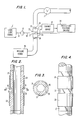
- a laser 11 generates a collimated laser beam 13, which is directed through to a beam expander 17.
- the beam 17 shapes the received laser beam into the form of a thin, flat sheet 19, which in the preferred embodiment, is 1 millimeter wide and 35 microns thick.
- the flat, sheet-like beam is transmitted through a transparent window 21 of a measuring cell 23, which is arranged to have a sample stream of fluid to be tested, flowing through the laser beam.
- the plane of the flat shape of the beam is perpendicular to the direction of fluid flow.
- the fluid is liquid, but the invention is also applicable to measuring the size of particles entrained in gases. Also, in the specific embodiment shown in Fig.
- the direction of flow is upward through the laser beam, but the cell may be oriented to have the flow in any direction.
- the laser beam is adapted to uniformly illuminate the cross section of the fluid passageway for carrying the fluid stream through the laser beam.
- the laser beam passing through the fluid stream in the cell 23, exits from the cell through an exit window 25 of the measuring cell.
- the laser light 19, encountering any particles in the fluid flowing through the cell 23, will be partially scattered by such particles.
- the cell 23 includes a transparent tube 27 extending vertically in both directions from the middle of the cell where the laser beam passes through the cell.
- the transparent tube 27 is surrounded by and has mounted on the tube walls photodetectors 29.
- the light scattered by particles passing through the laser beam is detected by the photodetectors 29, which convert the impinging scattered light rays into pulses.
- the pulses from the photodetectors 29 are summed in a summing circuit 31 into unitary pulses so that one pulses is produced for each particle and the pulses are applied to particle size measuring circuitry 33.
- the fluid entraining the particles to be measured is caused to flow through the cell 23 by means of a pressure source 35. Downstream of the cell is a valve 37, which controls the rate of flow through the cell 23 to be at a constant rate.
- the particle size measuring circuitry 33 measures particle sizes by the amplitude and width of pulses in the same manner as described in the above-described copending application Serial No. 144,225.
- the transparent tube 27 of the detecting cell 23 is round and has a round interior channel 1.5 millimeters in diameter.
- the round tubing at the center of the cell is formed with flat faces to define the entrance window 21 and the exit window 25 for the laser beam passing through the middle of the cell.
- the flat faces of the window 21 and 25 are formed by grooves 41 cut into the cylindrical wall of the tube 27.
- the grooves 41 are 0.5 millimeters wide measured from top to bottom as shown in Figure 2.
- the photodetectors 29 are cylindrical, completely surround the transparent tube 27, and extend upwardly and downwardly from the edges of the grooves 41.
- the photodetectors are formed on the cylindrical tube 27 by depositing amorphous silicon directly on the tube 27.
- the photodetectors 29 have an internal cylindrical photosensitive surface surrounding the fluid stream and operate in the photovoltaic mode to detect light impinging on the photosensitive surface.
- Additional photodetectors could also be deposited on the exterior tube wall on the sides of the tube between the grooves 41 to collect more of the light scattered from the laser beam by particles passing through the laser beam.
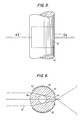
- the measurement cell shown in Figures 5 and 6, as in the embodiment of Figures 2 through 5, comprises a round transparent tube 42 in which photodetectors in the form of cylindrical segments 43 are formed on opposite sides of the tube at the center of the cell, each extending over an angle of 122 degrees.
- the photodetectors leave a gap of 44 degrees on one side of the tube to define an entrance window 45 for the laser beam and a gap of 40 degrees on the opposite side of the tube to define an exit window 46 for the laser beam.
- the laser beam 19 encountering the cylindrical face of the entrance window 45 will be focused upon passing through this cylindrical surface toward the cylindrical passage way 47 through which the fluid entraining the particles passes.
- the focusing provided by the arcuate face of the window 45 contracts the laser beam by an amount just to coincide with the size of the cylindrical passage way. In this manner, the laser beam 19 is concentrated by the focusing effect of the cylindrical passage way. In this manner, the laser beam 19 is concentrated by the focusing effect of the cylindrical face 45 to just fill the cross-section of the passageway 47 with the laser beam and so that the intensity of the laser beam encountered by the particles is intensified.
- the photodetectors 43 will detect light scattered from particles in the fluid stream passing through the laser beam 45 and generate an electrical pulse in response to each particle. If desired, additional photodetectors can be formed on the walls of the tube above and below the laser beam 45 in the gaps between the photodetectors 43 so as to collect additional scattered light from the particles.
- inventions of Figures 2-6 have the advantage of using round tubing.
- the detecting cell of these embodiments have the disadvantage of the difficulty of forming the photodetectors on the cylindrical tubing.
- the particle detecting cell is similar to that of Figures 2-6 except that the transparent tube of the cell, designated by reference number 51, is rectangular instead of round. Accordingly, instead of having a cylindrically shaped photodetecting cell formed on the transparent tube, the photodetecting cells comprise eight rectangular PIN photodiodes 52, four of them mounted on the rectangular walls directly above the laser beam and four of the cells mounted directly on the walls below the laser beam surrounding the rectangular tubing above and below the laser beam.
- the photosensitive surfaces of the photodiodes 52 face and surround the fluid stream.
- the photodiodes on the front and rear faces of the rectangular tube are spaced apart by .5 millimeters to define an entrance window 54 and an exit window 56 for the laser beam to enter the cell and exit from the cell.
- the rectangular tube's exterior dimension is 3 millimeters square and the rectangular channel within the cell has an interior dimension of 1.3 millimeters on each side.
- the photodetectors are rectangular, they do not have to be formed by being deposited on the tubing wall, but can be mounted on the tubing wall by means of a transparent adhesive. Thus, conventional semiconductor photodiodes may be used.
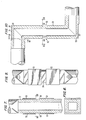
- the tubing 58 of the cell which is round, is formed into right angle bends 59 at its upper and lower ends to define horizontal sections of the cell.
- grooves 62 are formed 0.5 millimeters wide in the exterior cylindrical wall of the cell to define the flat faces 64 and 66 for the entrance and exit windows of the cell and through which the laser beam is directed.
- the interior wall surfaces of the vertical portion of the tubing 58 are mirrored with a specularly reflecting coating 67.
- the coating 67 extends up and down to the point where the tubing makes the right angle bends 59.
- a flat 68 is formed in the exterior wall of the tube directly in line with the axis of the vertical portion of the tube. These flats 68 extend from the corner of the tube to beyond the cylindrical locus of the exterior opposite vertical wall of the tube, so that the flats 68 overlap the entire cylindrical locus of the mirrored surfaces.
- PIN photodiodes 70 Mounted on and fully coextensive with the flats are PIN photodiodes 70.
- the photosensitive surfaces of the photodiodes 70 face the fluid stream and are adjacent to the internal wall of the tube that shapes flow of the fluid stream.
- the tubing of the cell conveniently is made out of glass and may be transparent throughout its length. However, it is only necessary for the tubing in this embodiment to be transparent opposite the entrance and exit windows 64 and 66 and opposite the photodiodes 70.
- the mirrored surfaces may also be provided on the exterior walls in which case the vertical portions of the tubing would have to be transparent.
- the exterior surface of the tube can be left round to achieve a focussing effect, like the embodiment of Figures 5 and 6 to concentrate the laser beam in the fluid passageway of the cell.
- the embodiment of the particle detecting cell shown in Figure 13 is like that shown in Figures 10-12, except that the tubing 72 of the cell, instead of being round, is rectangular. As a result, no grooves are defined in the wall of the cell to define flat windows for the cell and no flats need to be provided in the wall of the cell where the tube bends.
- PIN photodiodes 74 are mounted directly on the exterior flat surfaces of the cell where the tube makes right angle bends with the photodiode extending from sidewall to sidewall of the tube and from the corner of the tube to a point beyond the locus of the vertical extension of the opposite exterior wall of the tube, so that the photodiodes 74 overlap the locus of the rectangular mirrored surface provided by the specular coating 76 of the tube on the interior channel of the tube on all four sides.
- the specular coating 76 of the tube will reflect the scattered light to the photodiodes 74 as in the embodiment of Figures 10-12.
- the mirrored surfaces may be formed on the external surface of the tube instead of the internal surface.
- the tubing is transparent and conveniently may be made out of glass.
- the light scattered from a particle passing through the laser beam is very efficiently collected by the photodetectors, because essentially almost all of the light scattered from each particle, except for a small portion backwards scattered out of the entrance window or forward scattered out of the exit window, is collected by the photovoltaic cells.
- the cells generate relatively high amplitude pulses in response to the light scattered from a given particle and enables the particle sizes to be discriminated with the greater degree of accuracy. Also the need for lenses to collect the scattered light and focus it on a photodetector is eliminated.
Abstract
In an instrument for measuring the size of particles entrained in a fluid stream, photodetectors are mounted on the walls of tubing shaping the flow of the fluid stream through a laser beam. The photodetectors generate electric current pulses in response to scattering of the light which is generated by the particles passing through the laser beam. The pulses generated by the photodetectors provide a measurement of particle size. The photodetectors are mounted either adjacent to the laser beam on the tubing walls or, alternatively, the tubing walls are mirrored above and below the laser beam and the photodetectors are mounted on the tubing walls at right angle bends of the tubing to receive the light reflected from the mirrored surfaces.
Description
- This invention relates to an instrument for measuring particle sizes entrained in a fluid stream and, more particularly, to an instrument which measures particle sizes by light scattering from the particles as the particles pass through a beam of light directed through the stream in which the particles are entrained.
- In copending application Serial No. 144,225, filed January 15, 1988, invented by Kenneth Paul VonBargen and assigned to the assignee of this application, there is disclosed a particle measuring instrument of the general type to which the present invention is directed. As disclosed in the above-identified copending application, particles entrained in a fluid are measured by passing a beam of light through the fluid stream, detecting the resulting light forward scattered from particles passing through the light beam to generate pulses and determining the amplitude and the length of the resulting pulses as measurements of the particle sizes.
- The present invention is an improvement in the instrument of the above-described application in that it provides a more efficient method of detecting the light scattered from particles passing through a shaped light beam, which in the preferred embodiment is a laser beam. In accordance with the invention, instead of detecting the light forward scattered from particles passing through the light beam, photodetectors are mounted on the wall of the tubing which shapes the flow of the stream passing through the light beam. In accordance with one embodiment of the invention, the tubing extending away from the middle of the measurement cell is transparent and photodetectors surround the transparent tube immediately above and below the laser beam. In accordance with another embodiment of the invention, mirrored surfaces are provided on the walls of the tubing immediately above and below the laser beam to reflect the light to photodetectors mounted on the wall of the tubing where the tubing is formed into right angle bends. With these arrangements, more of the light scattered from particles passing through the laser beam is collected directly on the surfaces of the photodetectors and, thus, the scattered light is detected more efficiently than in the instrument described in the above-mentioned copending application, or in other particle measuring instruments which measure particle size by light scattered from entrained particles.
-
- Figure 1 schematically illustrates a particle size measuring instrument in accordance with the present invention;
- Figure 2 is an enlarged sectional view in elevation taken through the measuring cell of the instrument in accordance with one embodiment of the invention;
- Figure 3 is a cross-sectional view taken along the line 3-3 in Figure 2;
- Figure 4 is a side view in elevation of the measuring cell shown in Figure 2;
- Figure 5 is a side view in elevation of a measuring cell of the instrument in accordance with another embodiment of the invention;
- Figure 6 is a cross sectional view of the measuring cell of Figure 5 taken along the line 6-6;
- Figure 7 is an enlarged sectional view in elevation of the measuring cell of the instrument in accordance with another embodiment of the invention;
- Figure 8 is a cross-sectional view taken along the line 8-8 of Figure 7;
- Figure 9 is a side view in elevation of the measuring cell shown in Figure 7;
- Figure 10 is an enlarged sectional view in elevation of the measuring cell of the instrument in accordance with another embodiment of the invention;
- Figure 11 is a cross-Sectional view taken a long the line 11-11 of the measuring cell as shown in Figure 10;
- Figure 12 is a sectional view taken along the line 12-12 through the measuring cell as shown in Figure 10; and
- Figure 13 is an enlarged sectional view in elevation of the measuring cell of the instrument in accordance with another embodiment of the invention.
- As shown in Figure 1, in the instrument of the invention, a laser 11 generates a collimated
laser beam 13, which is directed through to abeam expander 17. Thebeam 17 shapes the received laser beam into the form of a thin,flat sheet 19, which in the preferred embodiment, is 1 millimeter wide and 35 microns thick. The flat, sheet-like beam is transmitted through atransparent window 21 of ameasuring cell 23, which is arranged to have a sample stream of fluid to be tested, flowing through the laser beam. The plane of the flat shape of the beam is perpendicular to the direction of fluid flow. In the specific embodiments, the fluid is liquid, but the invention is also applicable to measuring the size of particles entrained in gases. Also, in the specific embodiment shown in Fig. 1, the direction of flow is upward through the laser beam, but the cell may be oriented to have the flow in any direction. The laser beam is adapted to uniformly illuminate the cross section of the fluid passageway for carrying the fluid stream through the laser beam. The laser beam, passing through the fluid stream in thecell 23, exits from the cell through anexit window 25 of the measuring cell. Thelaser light 19, encountering any particles in the fluid flowing through thecell 23, will be partially scattered by such particles. Thecell 23 includes atransparent tube 27 extending vertically in both directions from the middle of the cell where the laser beam passes through the cell. Thetransparent tube 27 is surrounded by and has mounted on thetube walls photodetectors 29. The light scattered by particles passing through the laser beam is detected by thephotodetectors 29, which convert the impinging scattered light rays into pulses. The pulses from thephotodetectors 29 are summed in asumming circuit 31 into unitary pulses so that one pulses is produced for each particle and the pulses are applied to particlesize measuring circuitry 33. The fluid entraining the particles to be measured is caused to flow through thecell 23 by means of apressure source 35. Downstream of the cell is avalve 37, which controls the rate of flow through thecell 23 to be at a constant rate. The particlesize measuring circuitry 33 measures particle sizes by the amplitude and width of pulses in the same manner as described in the above-described copending application Serial No. 144,225. - In the embodiment of the invention illustrated in Figures 2-4, the
transparent tube 27 of the detectingcell 23 is round and has a round interior channel 1.5 millimeters in diameter. The round tubing at the center of the cell is formed with flat faces to define theentrance window 21 and theexit window 25 for the laser beam passing through the middle of the cell. The flat faces of thewindow tube 27. The grooves 41 are 0.5 millimeters wide measured from top to bottom as shown in Figure 2. Thephotodetectors 29 are cylindrical, completely surround thetransparent tube 27, and extend upwardly and downwardly from the edges of the grooves 41. The photodetectors are formed on thecylindrical tube 27 by depositing amorphous silicon directly on thetube 27. Thephotodetectors 29 have an internal cylindrical photosensitive surface surrounding the fluid stream and operate in the photovoltaic mode to detect light impinging on the photosensitive surface. - Additional photodetectors could also be deposited on the exterior tube wall on the sides of the tube between the grooves 41 to collect more of the light scattered from the laser beam by particles passing through the laser beam.
- The measurement cell shown in Figures 5 and 6, as in the embodiment of Figures 2 through 5, comprises a round
transparent tube 42 in which photodetectors in the form ofcylindrical segments 43 are formed on opposite sides of the tube at the center of the cell, each extending over an angle of 122 degrees. The photodetectors leave a gap of 44 degrees on one side of the tube to define anentrance window 45 for the laser beam and a gap of 40 degrees on the opposite side of the tube to define anexit window 46 for the laser beam. As shown in Figure 6, thelaser beam 19 encountering the cylindrical face of theentrance window 45 will be focused upon passing through this cylindrical surface toward thecylindrical passage way 47 through which the fluid entraining the particles passes. The focusing provided by the arcuate face of thewindow 45 contracts the laser beam by an amount just to coincide with the size of the cylindrical passage way. In this manner, thelaser beam 19 is concentrated by the focusing effect of the cylindrical passage way. In this manner, thelaser beam 19 is concentrated by the focusing effect of thecylindrical face 45 to just fill the cross-section of thepassageway 47 with the laser beam and so that the intensity of the laser beam encountered by the particles is intensified. - As in the embodiments of Figures 2 through 4, the
photodetectors 43 will detect light scattered from particles in the fluid stream passing through thelaser beam 45 and generate an electrical pulse in response to each particle. If desired, additional photodetectors can be formed on the walls of the tube above and below thelaser beam 45 in the gaps between thephotodetectors 43 so as to collect additional scattered light from the particles. - The embodiments of Figures 2-6 have the advantage of using round tubing. However, the detecting cell of these embodiments have the disadvantage of the difficulty of forming the photodetectors on the cylindrical tubing.
- In the embodiment of Figures 7-9, the particle detecting cell is similar to that of Figures 2-6 except that the transparent tube of the cell, designated by
reference number 51, is rectangular instead of round. Accordingly, instead of having a cylindrically shaped photodetecting cell formed on the transparent tube, the photodetecting cells comprise eightrectangular PIN photodiodes 52, four of them mounted on the rectangular walls directly above the laser beam and four of the cells mounted directly on the walls below the laser beam surrounding the rectangular tubing above and below the laser beam. The photosensitive surfaces of thephotodiodes 52 face and surround the fluid stream. The photodiodes on the front and rear faces of the rectangular tube are spaced apart by .5 millimeters to define anentrance window 54 and anexit window 56 for the laser beam to enter the cell and exit from the cell. The rectangular tube's exterior dimension is 3 millimeters square and the rectangular channel within the cell has an interior dimension of 1.3 millimeters on each side. - Because the photodetectors are rectangular, they do not have to be formed by being deposited on the tubing wall, but can be mounted on the tubing wall by means of a transparent adhesive. Thus, conventional semiconductor photodiodes may be used.
- In the embodiment of the particle measuring cell shown in Figures 10-12, the
tubing 58 of the cell, which is round, is formed into right angle bends 59 at its upper and lower ends to define horizontal sections of the cell. In the center of the cell,grooves 62 are formed 0.5 millimeters wide in the exterior cylindrical wall of the cell to define the flat faces 64 and 66 for the entrance and exit windows of the cell and through which the laser beam is directed. - The interior wall surfaces of the vertical portion of the
tubing 58, that is, the portions extending vertically from the center of the cell where the grooves are formed, are mirrored with a specularly reflecting coating 67. The coating 67 extends up and down to the point where the tubing makes the right angle bends 59. At eachright angle bend 59, a flat 68 is formed in the exterior wall of the tube directly in line with the axis of the vertical portion of the tube. Theseflats 68 extend from the corner of the tube to beyond the cylindrical locus of the exterior opposite vertical wall of the tube, so that theflats 68 overlap the entire cylindrical locus of the mirrored surfaces. Mounted on and fully coextensive with the flats arePIN photodiodes 70. The photosensitive surfaces of thephotodiodes 70 face the fluid stream and are adjacent to the internal wall of the tube that shapes flow of the fluid stream. The tubing of the cell conveniently is made out of glass and may be transparent throughout its length. However, it is only necessary for the tubing in this embodiment to be transparent opposite the entrance andexit windows photodiodes 70. - Instead of providing the mirrored surfaces on the internal walls of the tubing, the mirrored surfaces may also be provided on the exterior walls in which case the vertical portions of the tubing would have to be transparent. Instead of employing flats for the entrance and exit windows, the exterior surface of the tube can be left round to achieve a focussing effect, like the embodiment of Figures 5 and 6 to concentrate the laser beam in the fluid passageway of the cell.
- When a laser beam encounters a particle in the center of the cell shown in Figs. 10-12 and causes light to be scattered from such particle, the scattered light will be reflected one or more times from the specular coating 67 of the cell and be directed on the
photodiodes 70 whereupon the scattered light will be detected and converted into electric pulses. - The embodiment of the particle detecting cell shown in Figure 13 is like that shown in Figures 10-12, except that the
tubing 72 of the cell, instead of being round, is rectangular. As a result, no grooves are defined in the wall of the cell to define flat windows for the cell and no flats need to be provided in the wall of the cell where the tube bends. Instead,PIN photodiodes 74 are mounted directly on the exterior flat surfaces of the cell where the tube makes right angle bends with the photodiode extending from sidewall to sidewall of the tube and from the corner of the tube to a point beyond the locus of the vertical extension of the opposite exterior wall of the tube, so that thephotodiodes 74 overlap the locus of the rectangular mirrored surface provided by thespecular coating 76 of the tube on the interior channel of the tube on all four sides. In this embodiment, thespecular coating 76 of the tube will reflect the scattered light to thephotodiodes 74 as in the embodiment of Figures 10-12. Also in this embodiment, the mirrored surfaces may be formed on the external surface of the tube instead of the internal surface. As in the embodiment of Figure 10-12, the tubing is transparent and conveniently may be made out of glass. - In each of the above described embodiments, the light scattered from a particle passing through the laser beam is very efficiently collected by the photodetectors, because essentially almost all of the light scattered from each particle, except for a small portion backwards scattered out of the entrance window or forward scattered out of the exit window, is collected by the photovoltaic cells. As a result, the cells generate relatively high amplitude pulses in response to the light scattered from a given particle and enables the particle sizes to be discriminated with the greater degree of accuracy. Also the need for lenses to collect the scattered light and focus it on a photodetector is eliminated.
- The above description is of preferred embodiments of the invention and modification may be made thereto without departing from the spirit and scope of the invention, which is defined in the appended claims.
Claims (12)
1. A particle measuring system comprising a tube, means to cause fluid entraining particles to be measured to pass through said tube in a fluid stream, said tube having an interior wall surface shaping the flow of said stream, means to direct a shaped beam of light through said stream in said tube perpendicular to the direction of flow of said stream, and at least one photodetector having a photosensitive surface mounted on the wall of said tube with said photosensitive surface positioned adjacent to said interior wall surface and arranged to detect the light scattered from said beam of light by particles in said stream passing through said beam of light.
2. A particle measuring instrument as recited in claim 1, wherein said photodetector is mounted on the wall of said tube to position said photosensitive surface adjacent to said light beam as it passes through said fluid stream.
3. A particle measuring instrument as recited in claim 2, wherein said tube is transparent, said photodetector is mounted on the outside wall of said tube with said photosensitive surface facing said fluid stream.
4. A particle measuring instrument as recited in claim 2, wherein said photosensitive surface surrounds said stream adjacent to said light beam passing through said tube.
5. A particle measuring instrument as recited in claim 2, wherein said tube is rectangular in cross-section.
6. A particle measuring instrument as recited in claim 2, wherein said tube is round and said photosensitive surface is cylindrical.
7. A particle measuring instrument as recited in claim 6, wherein a second photodetector is mounted on the wall of said tube having a cylindrical photosensitive surface facing said stream adjacent said light beam passing through said stream, said light beam passing through the walls of said tube between said photodetectors.
8. A particle measuring instrument as recited in claim 7, wherein said tube has flat surfaces defined in the exterior wall of said tube between said photodetectors, said light beam passing through said flat surfaces.
9. A particle measuring instrument as recited in claim 1, wherein said tube has a right angle bend, and wherein a mirrored surface is formed on the wall of said tube adapted to reflect light scattered from said beam light by particles in said stream, said mirrored surface extending from a location adjacent said beam of light passing through said stream to said right angle bend, said photodetector being mounted on the wall of said tube with said photosensitive surface positioned to receive the light scattered from said beam and reflected by said mirrored surface.
10. A particle measuring instrument as recited in claim 1, wherein said tube is round defining a cylindrical surface through which said beam of light passes to enter said stream, said cylindrical surface focusing said beam to concentrate said beam in said stream.
11. A particle measuring instrument as recited in claim 10, wherein said photodetector is mounted on the exterior wall of said tube and wherein the wall of said tube is transparent adjacent to said photosensitive surface.
12. A particle measuring instrument as recited in claim 10, wherein said photodetector is mounted on the wall of said tube to position said photosensitive surface adjacent to said light beam as it passes through said fluid stream, and a second photodetector is mounted on the wall of said tube opposite said first mentioned photodetector and having a photosensitive surface facing the photosensitive surface of said first photodetector, said cylindrical external surface of said tube extending between said photodetectors, said light beam passing through said stream between said oppositely facing photosensitive surfaces.
Applications Claiming Priority (2)
| Application Number | Priority Date | Filing Date | Title |
|---|---|---|---|
| US07/217,337 US4917496A (en) | 1988-07-11 | 1988-07-11 | Particle size measuring instrument with direct scattered light detection |
| US217337 | 1988-07-11 |
Publications (2)
| Publication Number | Publication Date |
|---|---|
| EP0350768A2 true EP0350768A2 (en) | 1990-01-17 |
| EP0350768A3 EP0350768A3 (en) | 1991-02-27 |
Family
ID=22810637
Family Applications (1)
| Application Number | Title | Priority Date | Filing Date |
|---|---|---|---|
| EP19890112179 Withdrawn EP0350768A3 (en) | 1988-07-11 | 1989-07-04 | Particle size measuring instrument with direct scattered light detection |
Country Status (3)
| Country | Link |
|---|---|
| US (1) | US4917496A (en) |
| EP (1) | EP0350768A3 (en) |
| JP (1) | JPH0266427A (en) |
Cited By (6)
| Publication number | Priority date | Publication date | Assignee | Title |
|---|---|---|---|---|
| EP0864855A1 (en) * | 1997-03-10 | 1998-09-16 | Fuji Electric Co., Ltd. | Method and apparatus for measuring turbidity |
| DE19724228A1 (en) * | 1997-06-03 | 1998-12-10 | Holger Dyja | Method for measuring size distribution, optical characteristics or particle concentration |
| WO2002073165A2 (en) * | 2001-03-14 | 2002-09-19 | Facility Monitoring Systems Limited | Photodetector for particle counting |
| GB2411002A (en) * | 2004-02-11 | 2005-08-17 | Facility Monitoring Systems Lt | Liquid particle counter with a glass tube sample cell |
| ES2607633A1 (en) * | 2015-10-01 | 2017-04-03 | Universidad Carlos Iii De Madrid | Multiple loading device for flat laser beam microscope (Machine-translation by Google Translate, not legally binding) |
| CN110849817A (en) * | 2019-10-21 | 2020-02-28 | 中国科学院大气物理研究所 | Single-particle polarized optical property and optical particle size spectrum measuring system |
Families Citing this family (18)
| Publication number | Priority date | Publication date | Assignee | Title |
|---|---|---|---|---|
| US4976871A (en) * | 1989-10-17 | 1990-12-11 | Nalco Chemical Company | Method of monitoring flocculant effectiveness |
| US5092675A (en) * | 1989-11-14 | 1992-03-03 | Pacific Scientific Company | Vacuum line particle detector with slab laser |
| US4999512A (en) * | 1989-12-04 | 1991-03-12 | Zito Richard R | Optical powder impurity detector |
| JPH03239949A (en) * | 1990-02-16 | 1991-10-25 | Rion Co Ltd | Cell for particle detector |
| JP3102935B2 (en) * | 1991-11-20 | 2000-10-23 | シスメックス株式会社 | Imaging flow cytometer |
| US5534999A (en) * | 1993-03-05 | 1996-07-09 | Shinmikuni Kikai Ltd. | Monitoring sub-micron particles |
| US5481357A (en) * | 1994-03-03 | 1996-01-02 | International Business Machines Corporation | Apparatus and method for high-efficiency, in-situ particle detection |
| US5438420A (en) * | 1993-08-09 | 1995-08-01 | Vickers, Incorporated | Monitoring of fluid contamination level wherein the light energy is focused on the fluid passage means |
| US5805281A (en) * | 1997-04-21 | 1998-09-08 | Particle Measuring Systems | Noise reduction utilizing signal multiplication |
| US5939727A (en) * | 1997-12-22 | 1999-08-17 | Caterpillar Inc. | Contamination sensor |
| CA2432182A1 (en) * | 2000-12-28 | 2002-07-11 | Borealis Technology Oy | Apparatus and process for measuring flowing bulk material by light-reflection |
| EP1432972A1 (en) * | 2001-09-07 | 2004-06-30 | Inficon, Inc. | Signal processing method for in-situ, scanned-beam particle monitoring |
| GB0323055D0 (en) * | 2003-10-02 | 2003-11-05 | Unidata Europ Ltd | Particulate detector |
| EP2232231A4 (en) | 2007-12-04 | 2015-12-02 | Particle Measuring Syst | Non-orthogonal particle detection systems and methods |
| US9007580B2 (en) | 2011-04-11 | 2015-04-14 | Schlumberger Norge As | Method and apparatus for measuring particle size distribution in drilling fluid |
| WO2010048276A2 (en) * | 2008-10-23 | 2010-04-29 | M-I L.L.C. | Method and apparatus for measuring particle size distribution in drilling fluid |
| US20210148810A1 (en) * | 2019-11-15 | 2021-05-20 | Becton, Dickinson And Company | Methods for determining particle size and light detection systems for same |
| US11275014B1 (en) | 2021-05-03 | 2022-03-15 | Roy Olson | Particle characteristic measurement apparatus |
Citations (3)
| Publication number | Priority date | Publication date | Assignee | Title |
|---|---|---|---|---|
| US3200700A (en) * | 1959-04-23 | 1965-08-17 | Bowser Inc | Photoelectric comparison apparatus for indicating the amount of contamination in liquids |
| EP0059115A1 (en) * | 1981-01-14 | 1982-09-01 | ETAT FRANCAIS représenté par Le Ministère de l'Urbanisme et du Logement LABORATOIRE CENTRAL DES PONTS ET CHAUSSEES | Method and device for measurement by means of projected shadows |
| US4783599A (en) * | 1987-02-10 | 1988-11-08 | High Yield Technology | Particle detector for flowing liquids with the ability to distinguish bubbles via photodiodes disposed 180° apart |
Family Cites Families (11)
| Publication number | Priority date | Publication date | Assignee | Title |
|---|---|---|---|---|
| US3680962A (en) * | 1969-09-08 | 1972-08-01 | Tokyo Keiki Seizosho Co Ltd | Contaminant detector comprising means for selectively applying pressure to liquify bubbles |
| US3770351A (en) * | 1971-11-23 | 1973-11-06 | Science Spectrum | Optical analyzer for microparticles |
| US4361403A (en) * | 1978-06-26 | 1982-11-30 | Loos Hendricus G | Multiple wavelength instrument for measurement of particle size distributions |
| JPS5580039A (en) * | 1978-12-12 | 1980-06-16 | Hiroshi Sato | Integrating sphare type turbidimeter |
| ATE19302T1 (en) * | 1981-06-04 | 1986-05-15 | Atomic Energy Authority Uk | MEASUREMENT OF THE PARTICLE SIZE. |
| US4387993A (en) * | 1981-06-25 | 1983-06-14 | Tsi Incorporated | Particle size measuring method and apparatus |
| US4507556A (en) * | 1982-12-08 | 1985-03-26 | St. Regis Paper Company | Apparatus and method for determining pulp stock consistency |
| JPS60501719A (en) * | 1983-06-30 | 1985-10-11 | コモンウエルス サイエンテイフイツク アンド インダストリアル リサ−チ オ−ガニゼ−シヨン | Optical-based measurement of fluid parameters |
| US4801205A (en) * | 1984-06-30 | 1989-01-31 | Kabushiki Kaisha Toshiba | Particle size measuring apparatus |
| US4830494A (en) * | 1986-07-10 | 1989-05-16 | Kowa Company Ltd. | Method and apparatus for measuring particles in a fluid |
| US4772126A (en) * | 1986-10-23 | 1988-09-20 | Inspex Incorporated | Particle detection method and apparatus |
-
1988
- 1988-07-11 US US07/217,337 patent/US4917496A/en not_active Expired - Fee Related
-
1989
- 1989-07-04 EP EP19890112179 patent/EP0350768A3/en not_active Withdrawn
- 1989-07-07 JP JP1176979A patent/JPH0266427A/en active Pending
Patent Citations (3)
| Publication number | Priority date | Publication date | Assignee | Title |
|---|---|---|---|---|
| US3200700A (en) * | 1959-04-23 | 1965-08-17 | Bowser Inc | Photoelectric comparison apparatus for indicating the amount of contamination in liquids |
| EP0059115A1 (en) * | 1981-01-14 | 1982-09-01 | ETAT FRANCAIS représenté par Le Ministère de l'Urbanisme et du Logement LABORATOIRE CENTRAL DES PONTS ET CHAUSSEES | Method and device for measurement by means of projected shadows |
| US4783599A (en) * | 1987-02-10 | 1988-11-08 | High Yield Technology | Particle detector for flowing liquids with the ability to distinguish bubbles via photodiodes disposed 180° apart |
Non-Patent Citations (1)
| Title |
|---|
| ANALYTICAL CHEMISTRY, vol. 61, no. 8, 15th April 1989, pages 876-883, American Chemical Society, Columbus, US; A.E. BRUNO et al.: "On-column capillary flow cell utilizing optical waveguides for chromatographic applications" * |
Cited By (11)
| Publication number | Priority date | Publication date | Assignee | Title |
|---|---|---|---|---|
| EP0864855A1 (en) * | 1997-03-10 | 1998-09-16 | Fuji Electric Co., Ltd. | Method and apparatus for measuring turbidity |
| US6184983B1 (en) | 1997-03-10 | 2001-02-06 | Fuji Electric Co., Ltd. | Method and apparatus for measuring turbidity |
| DE19724228A1 (en) * | 1997-06-03 | 1998-12-10 | Holger Dyja | Method for measuring size distribution, optical characteristics or particle concentration |
| WO2002073165A2 (en) * | 2001-03-14 | 2002-09-19 | Facility Monitoring Systems Limited | Photodetector for particle counting |
| WO2002073165A3 (en) * | 2001-03-14 | 2003-01-09 | Facility Monitoring Systems Lt | Photodetector for particle counting |
| GB2411002A (en) * | 2004-02-11 | 2005-08-17 | Facility Monitoring Systems Lt | Liquid particle counter with a glass tube sample cell |
| GB2411002B (en) * | 2004-02-11 | 2006-12-20 | Facility Monitoring Systems Lt | Particle counter for liquids |
| ES2607633A1 (en) * | 2015-10-01 | 2017-04-03 | Universidad Carlos Iii De Madrid | Multiple loading device for flat laser beam microscope (Machine-translation by Google Translate, not legally binding) |
| WO2017055673A1 (en) * | 2015-10-01 | 2017-04-06 | Universidad Carlos Iii De Madrid | Multiple-loading device for a flat laser beam microscope |
| CN110849817A (en) * | 2019-10-21 | 2020-02-28 | 中国科学院大气物理研究所 | Single-particle polarized optical property and optical particle size spectrum measuring system |
| CN110849817B (en) * | 2019-10-21 | 2020-11-24 | 中国科学院大气物理研究所 | Single-particle polarized optical property and optical particle size spectrum measuring system |
Also Published As
| Publication number | Publication date |
|---|---|
| EP0350768A3 (en) | 1991-02-27 |
| US4917496A (en) | 1990-04-17 |
| JPH0266427A (en) | 1990-03-06 |
Similar Documents
| Publication | Publication Date | Title |
|---|---|---|
| US4917496A (en) | Particle size measuring instrument with direct scattered light detection | |
| US5861950A (en) | Particle detection system utilizing an inviscid flow-producing nozzle | |
| CA1126977A (en) | Ellipsoid-conic radiation collector and method | |
| US4728190A (en) | Device and method for optically detecting particles in a fluid | |
| US4942305A (en) | Integrating sphere aerosol particle detector | |
| US4341471A (en) | Apparatus and method for measuring the distribution of radiant energy produced in particle investigating systems | |
| US4885473A (en) | Method and apparatus for detecting particles in a fluid using a scanning beam | |
| US5726751A (en) | Silicon microchannel optical flow cytometer | |
| US5166537A (en) | Particle analyzing method and device for realizing same | |
| US5565984A (en) | Re-entrant illumination system for particle measuring device | |
| US5092675A (en) | Vacuum line particle detector with slab laser | |
| US4876458A (en) | Apparatus for measuring particles in liquid | |
| CA1135971A (en) | Radiant energy reradiating flow cell system and method | |
| US5155543A (en) | Adjustable flow cytometer | |
| RU2006108798A (en) | OPTICAL FLOW METER FOR MEASURING GAS AND LIQUID FLOW IN PIPELINES | |
| US7355706B2 (en) | Particle detection system implemented with an immersed optical system | |
| US4523841A (en) | Radiant energy reradiating flow cell system and method | |
| US20030137661A1 (en) | Multipass cavity for illumination and excitation of moving objects | |
| US8736837B2 (en) | Method and flow cell for characterizing particles by means of non-Gaussian temporal signals | |
| EP0594327A1 (en) | Capillary detector cell with imaging elements for optimizing sensitivity | |
| US5033851A (en) | Light scattering method and apparatus for detecting particles in liquid sample | |
| GB2058340A (en) | Measuring fluid flow | |
| EP1544600A1 (en) | Flow cell, and particle measurement device using the same | |
| JPH08114421A (en) | Non-contact type measuring device for measuring thickness ofmaterial body comprising transparent material | |
| US6104490A (en) | Multiple pathlength sensor for determining small particle size distribution in high particle concentrations |
Legal Events
| Date | Code | Title | Description |
|---|---|---|---|
| PUAI | Public reference made under article 153(3) epc to a published international application that has entered the european phase |
Free format text: ORIGINAL CODE: 0009012 |
|
| AK | Designated contracting states |
Kind code of ref document: A2 Designated state(s): DE FR GB |
|
| PUAL | Search report despatched |
Free format text: ORIGINAL CODE: 0009013 |
|
| AK | Designated contracting states |
Kind code of ref document: A3 Designated state(s): DE FR GB |
|
| STAA | Information on the status of an ep patent application or granted ep patent |
Free format text: STATUS: THE APPLICATION IS DEEMED TO BE WITHDRAWN |
|
| 18D | Application deemed to be withdrawn |
Effective date: 19910828 |