EP0349995A2 - Method for adapting a battery charger to different charging methods, battery types and battery charger - Google Patents
Method for adapting a battery charger to different charging methods, battery types and battery charger Download PDFInfo
- Publication number
- EP0349995A2 EP0349995A2 EP89112225A EP89112225A EP0349995A2 EP 0349995 A2 EP0349995 A2 EP 0349995A2 EP 89112225 A EP89112225 A EP 89112225A EP 89112225 A EP89112225 A EP 89112225A EP 0349995 A2 EP0349995 A2 EP 0349995A2
- Authority
- EP
- European Patent Office
- Prior art keywords
- battery
- program module
- battery charger
- charging
- program
- Prior art date
- Legal status (The legal status is an assumption and is not a legal conclusion. Google has not performed a legal analysis and makes no representation as to the accuracy of the status listed.)
- Withdrawn
Links
Images

Classifications
-
- H—ELECTRICITY
- H02—GENERATION; CONVERSION OR DISTRIBUTION OF ELECTRIC POWER
- H02J—CIRCUIT ARRANGEMENTS OR SYSTEMS FOR SUPPLYING OR DISTRIBUTING ELECTRIC POWER; SYSTEMS FOR STORING ELECTRIC ENERGY
- H02J7/00—Circuit arrangements for charging or depolarising batteries or for supplying loads from batteries
- H02J7/00047—Circuit arrangements for charging or depolarising batteries or for supplying loads from batteries with provisions for charging different types of batteries
Definitions
- the invention relates to a method for adapting a battery charger to different charging methods and battery types.
- Battery chargers for rechargeable batteries work with a wide variety of charging methods. For example, methods with constant current or constant voltage or combinations of both are used.
- the increased use of low-maintenance, dry battery types, for example in battery-powered vehicles, requires this use of short and economical charging procedures that are precisely tailored to the relevant battery type.
- the subtle differences between the individual battery types essentially consist in the current and voltage values to be observed during the recharge phase.
- a precise adaptation to the respective battery type is particularly advantageous if the respective charging time has to be optimized taking into account the service life of a battery. For this purpose, when changing the charging method or the type of battery, a new battery charger or a very complex new change of the old battery charger was required.
- the battery charger can be easily adapted to different charging methods and battery types by exchanging a parameter associated with the battery charger and battery, charging method, charging time and / or use-dependent parameters and possibly one or more charging methods in program form.
- the battery charger according to the invention has an exchangeable program module which contains the aforementioned data (parameters, programs).
- the interchangeable program module advantageously has at least one or more memories in which charging methods, charging characteristics and / or predetermined target values can be stored. These memories are the heart of the program module. They contain all the essentials charging process-typical parameters, time profiles etc.
- the battery charger can be adapted to any type of battery and charging method.
- a new battery charger or time-consuming retrofitting of the old battery charger is no longer necessary.
- processor with further control and auxiliary circuits for controlling the charging process in the battery charger, but outside the program module.
- the component (program module) to be replaced to adapt to a new battery type or a new charging process is therefore particularly small.
- the program module is designed as a programmable memory module, in particular as an EPROM.
- the program module can be manufactured particularly inexpensively in this way.
- program modules that have already been programmed can be reprogrammed to adapt them to special customer requirements.
- a battery charger 10 is provided with control electronics 11, which monitors the charging process of a connected battery 12.
- a program module 13 supplies charging process and battery-dependent information to the control electronics 11 and is plugged onto the latter (cf. FIG. 2).
- the program module 13 is exchanged accordingly by releasing a plug connection 14 in the area of the control electronics 11 and by inserting another program module.
- the control electronics 11 contains components, not shown in the figures, such as D / A converters, A / D converters, regulators, actuators and, if appropriate, display instruments.
- FIG. 3 shows another embodiment compared to FIG. 2, in which the program module 13 is connected to the battery 12, for example by a plug connection.
- the connection to the battery charger 10 is made via a signal line 16 parallel to the power connection 15.
- the program module 13 is connected to the battery due to the connection 12 always exchanged together with this and always supplies the control electronics 11 with the battery-specific information.
- the structure of the program module 13 is shown in FIG. 1.
- the essential components of the program module 13 are a program memory 17, a processor 18 and four potentiometers 19. .22.
- the program memory 17 contains all the important charging method-dependent and battery-typical data. It is designed as an erasable, programmable memory (EPROM).
- EPROM erasable, programmable memory
- the EPROM can be programmed according to the requirements and, if necessary, deleted and reprogrammed.
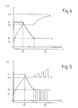
- FIGS. 4 and 5 show current and voltage as a function of time for different charging methods.
- the dashed line represents the voltage curve and the solid line represents the current curve over time.
- Characteristic voltage values during the charging process are the initial charge voltage U 1, the gassing voltage U 2 and the final charge voltage U 3. Accordingly, a distinction is made in the current between the initial charge current I 1 and the final charge current I 2.
- the charging process itself is divided into two phases, namely the main charging phase P1 and the reloading phase P2.
- the loading profiles shown in Figures 4 and 5 differ essentially in the reloading phase P2. These differences in the recharge phase P2 are usually caused by the use of different types of batteries, e.g. a gel battery as opposed to a wet battery.
- the program memory 17 accordingly contains all the information that is necessary to differentiate the different charging processes, such as the course of the current and the voltage over time.
- the voltage and current values mentioned are essentially battery-dependent and can be set by means of the potentiometers 19. 22 (according to FIG. 1), so that at Using the same charging method for similar batteries, only the potentiometers 19. .22 need to be adjusted and the program module 13 does not have to be replaced.
- the potentiometers 19. 22 are arranged on an end face 23 of the program module 13 and each have adjustment screws 24. 27. The latter are arranged so that they are accessible and adjustable from the outside even when the program module 13 is plugged onto the battery charger 10.
- the number of adjustable potentiometers depends on the number of current and voltage values to be set. For example, a maximum cell voltage before charging, a minimum cell voltage for the start of charging and a sulfation voltage could also be provided as changeable parameters. The number of potentiometers 19-22 would then have to be adjusted accordingly.
- a further component of the program module 13 according to FIG. 1 is the processor 18, which controls and monitors the actual loading process according to the loading method stored in the program memory 17 and the values set via the potentiometers 19 .22. To transmit the information, the program memory 17 and the potentiometers 19. 22 have leads 28. 33 to the processor 18.
- the program module 13 contains further components, resistors, capacitors and ICs which are required for operation, but which are familiar to the person skilled in the art and need not be described in the context of the invention.
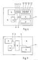
- FIG. 6 shows a schematic illustration of the charger 10 in a form slightly modified compared to FIGS. 1 and 2.
- Control electronics 11 and a reference voltage source 34 are permanently installed in the charger.
- the latter supplies processor 18 with a constant, highly accurate and digitized voltage value.
- the electrical quantities stored in the program memory 17 can thereby be based on the reference voltage be related.
- a corresponding reference voltage source can be contained in the control electronics 11.
- the program memory 17 and the processor 18 are part of the program module 13.
- the potentiometers 19 .22 with adjusting screws 24. .27 belong to the program module 13.
- the program module 13 can be detached from the battery charger 10 via a plug connection.
- the plug connection itself is not designated in more detail in FIG.
- the lines 39, 40 can each have several contain individual, separate conductors.
- FIG. 7 A further embodiment is shown in FIG. 7.
- the processor 18 is not arranged in the area of the program module 13, but rather is firmly arranged in the battery charger 10.
- lines 39, 40 are provided between processor 18 and control electronics 11 or processor 18 and reference voltage source 34.
- the program module 13 only consists of the program memory 17.
- the latter is an EPROM with a capacity of 8 kB.
- Programs for carrying out one or more charging methods and also battery setpoints are stored in the program memory 17. By storing the target values in the program memory 17, almost any number of them (only depending on the capacity of the memory) can be stored and taken into account during the loading process.
- the potentiometers 19 .22 provided in FIG. 6 for setting the setpoint are accordingly not present in FIG. 7.
- the program module 13 or the program memory 17 can be detached from the battery charger 10 via a plug connection.
- the connector (not shown explicitly) contains a line 41 between the program memory 17 and the processor 18 with possibly several separate conductors. This embodiment has the advantage that the component to be replaced is particularly small and therefore inexpensive. In addition, the number of conductors to be considered in the context of the plug connection is small.
- the processor 18 together with the program memory 17 is part of the program module 13.
- the lines 39, 40 can then be disconnected within the scope of the plug connection between the program module 13 and the battery charger 10.
- the battery charger 10 can be adapted to any charging method and each battery type by exchanging the plug-in program module 13.
Abstract
Description
Die Erfindung betrifft ein Verfahren zur Anpassung eines Batterieladegerätes an unterschiedliche Ladeverfahren und Batterietypen.The invention relates to a method for adapting a battery charger to different charging methods and battery types.
Batterieladegeräte für wiederaufladbare Batterien arbeiten mit unterschiedlichsten Ladeverfahren. So werden z.B. Verfahren mit Konstantstrom oder Konstantspannung bzw. Kombinationen aus beidem angewandt. Während des Ladevorganges wird im wesentlichen zwischen zwei Phasen unterschieden, nämlich einer Hauptladephase und einer Nachladephase. Der vermehrte Einsatz wartungsarmer, trockener Batterietypen, z.B. in batteriegetriebenen Fahrzeugen, erfordert die An wendung kurzer und ökonomischer Ladeverfahren, die genau auf den entsprechenden Batterietyp abgestimmt sind. Die feinen Unterschiede zwischen den einzelnen Batterietypen bestehen im wesentlichen in den einzuhaltenden Strom- und Spannungswerten während der Nachladephase. Eine genaue Anpassung an den jeweiligen Batterietyp ist insbesondere dann von Vorteil, wenn es die jeweilige Ladezeit unter Berücksichtigung der Lebensdauer einer Batterie zu optimieren gilt. Zu diesem Zweck war bisher bei Wechsel der Lademethode oder der Batterieart ein neues Batterieladegerät oder eine sehr aufwendige neuerliche Veränderung des alten Batterieladegerätes erforderlich.Battery chargers for rechargeable batteries work with a wide variety of charging methods. For example, methods with constant current or constant voltage or combinations of both are used. During the charging process, a distinction is essentially made between two phases, namely a main charging phase and a reloading phase. The increased use of low-maintenance, dry battery types, for example in battery-powered vehicles, requires this use of short and economical charging procedures that are precisely tailored to the relevant battery type. The subtle differences between the individual battery types essentially consist in the current and voltage values to be observed during the recharge phase. A precise adaptation to the respective battery type is particularly advantageous if the respective charging time has to be optimized taking into account the service life of a battery. For this purpose, when changing the charging method or the type of battery, a new battery charger or a very complex new change of the old battery charger was required.
Aufgabe der vorliegenden Erfindung ist es daher, ein Verfahren bereitzustellen, mit dem Batterieladegeräte an unterschiedliche Ladeverfahren und Batterietypen angepaßt werden können. Weitere Aufgabe der Erfindung ist es, ein Batterieladegerät zur Durchführung des genannten Verfahrens bereitzustellen.It is therefore an object of the present invention to provide a method with which battery chargers can be adapted to different charging methods and types of batteries. Another object of the invention is to provide a battery charger for carrying out the method mentioned.
Erfindungsgemäß wird die Aufgabe durch die kennzeichnenden Maßnahmen des Anspruchs 1 gelöst. Durch den Austausch eines dem Batterieladegerät zugeordneten und batterie-, ladeverfahrens-, ladezeit- und/oder einsatzabhängige Parameter sowie gegebenenfalls ein oder mehrere Ladeverfahren in Programmform enthaltenden Programmoduls kann das Batterieladegerät leicht an unterschiedliche Ladeverfahren und Batterietypen angepaßt werden.According to the invention the object is achieved by the characterizing measures of
Dementsprechend weist das erfindungsgemäße Batterieladegerät ein austauschbares Programmodul auf, das die zuvor genannten Daten (Parameter, Programme) enthält.Accordingly, the battery charger according to the invention has an exchangeable program module which contains the aforementioned data (parameters, programs).
Vorteilhafterweise weist das austauschbare Programmodul zumindest einen oder mehrere Speicher auf, in denen Ladeverfahren, Ladekennlinien und/oder vorgegebene Sollwerte abspeicherbar sind. Diese Speicher sind das eigentliche Herzstück des Programmoduls. Sie beinhalten alle wesentlichen ladeverfahrenstypischen Parameter, Zeitverläufe usw.The interchangeable program module advantageously has at least one or more memories in which charging methods, charging characteristics and / or predetermined target values can be stored. These memories are the heart of the program module. They contain all the essentials charging process-typical parameters, time profiles etc.
Durch einen einfachen Austausch des Programmoduls kann das Batterieladegerät an jeden Batterietyp und an jedes Ladeverfahren angepaßt werden. Ein neues Batterieladegerät oder eine aufwendige Umrüstung des alten Batterieladegerätes sind nicht mehr erforderlich.By simply replacing the program module, the battery charger can be adapted to any type of battery and charging method. A new battery charger or time-consuming retrofitting of the old battery charger is no longer necessary.
Weitere Merkmale der Erfindung betreffen die Ausgestaltung des Programmoduls sowie die Anordnung von weiteren zur Durchführung der gewünschten Ladeverfahren vorteilhaften Bauteilen und sind den Unteransprüche zu entnehmen.Further features of the invention relate to the design of the program module and the arrangement of further components which are advantageous for carrying out the desired charging process and can be found in the subclaims.
Besonders vorteilhaft ist es, einen Prozessor mit weiteren Regel- und Hilfsschaltungen zur Steuerung des Ladevorgangs im Batterieladegerät, jedoch außerhalb des Programmoduls anzuordnen. Das zur Anpassung an einen neuen Batterietyp oder ein neues Ladeverfahren auszuwechselnde Bauteil (Programmodul) fällt dadurch besonders klein aus.It is particularly advantageous to arrange a processor with further control and auxiliary circuits for controlling the charging process in the battery charger, but outside the program module. The component (program module) to be replaced to adapt to a new battery type or a new charging process is therefore particularly small.
In einer weiteren vorteilhaften Ausführungsform ist das Programmodul als programmierbarer Speicherbaustein, insbesondere als EPROM ausgebildet. Das Programmodul kann auf diese Weise besonders preiswert hergestellt werden. Außerdem können gegebenenfalls bereits programmierte Programmmodule zur Anpassung an besondere Kundenwünsche umprogrammiert werden.In a further advantageous embodiment, the program module is designed as a programmable memory module, in particular as an EPROM. The program module can be manufactured particularly inexpensively in this way. In addition, program modules that have already been programmed can be reprogrammed to adapt them to special customer requirements.
Ausführungsbeispiele der Erfindung werden nachstehend anhand von Zeichnungen näher erläutert. Es zeigen:
- Fig. 1 ein Programmodul zum Anschluß an ein Batterieladegerät in der schematischen Draufsicht,
- Fig. 2 ein Batterieladegerät mit einem angeschlossenen bzw. aufgesteckten Programmodul und einer zu ladenden Batterie,
- Fig. 3 ein Batterieladegerät wie in Fig. 2, wobei jedoch das Programmodul mit der Batterie verbunden und parallel zu dieser an das Batterieladegerät angeschlossen ist,
- Fig. 4 Strom und Spannung als Funktion der Zeit für ein bestimmtes Ladeverfahren,
- Fig. 5 Strom und Spannung als Funktion der Zeit wie in Fig. 4, jedoch für ein anderes Ladeverfahren,
- Fig. 6 ein Batterieladegerät mit den zur Steuerung erforderlichen Komponenten in schematischer Darstellung, und
- Fig. 7 ein Batterieladegerät in einer gegenüber der Fig. 6 abgewandelten Ausführungsform, ebenfalls in schematischer Darstellung.
- 1 shows a program module for connection to a battery charger in a schematic plan view,
- 2 shows a battery charger with a connected or plugged-in program module and a battery to be charged,
- 3 shows a battery charger as in FIG. 2, but with the program module connected to the battery and connected in parallel to the battery charger,
- 4 current and voltage as a function of time for a specific charging method,
- 5 current and voltage as a function of time as in FIG. 4, but for a different charging method,
- Fig. 6 shows a battery charger with the components required for control in a schematic representation, and
- FIG. 7 shows a battery charger in an embodiment modified from FIG. 6, also in a schematic illustration.
Ein Batterieladegerät 10 ist mit einer Steuerelektronik 11 versehen, die den Ladevorgang einer angeschlossenen Batterie 12 überwacht. Ein Programmodul 13 liefert ladeverfahrens- und batterieabhängige Informationen an die Steuerelektronik 11 und ist auf diese aufgesteckt (vgl. Fig. 2). Bei einem Wechsel des Ladeverfahrens oder des Batterietyps wird das Programmodul 13 entsprechend ausgetauscht durch Lösen einer Steckverbindung 14 im Bereich der Steuerelektronik 11 und durch Einsetzen eines anderen Programmoduls. Die Steuerelektronik 11 enthält in den Figuren nicht dargestellte Bauteile wie D/A-Wandler, A/D-Wandler, Regler, Stellglieder und gegebenenfalls Anzeigeinstrumente.A
Die Fig. 3 zeigt gegenüber der Fig. 2 eine andere Ausführungsform, bei der das Programmodul 13 mit der Batterie 12, etwa durch eine Steckverbindung, verbunden ist. Die Verbindung zum Batterieladegerät 10 erfolgt über eine zur Starkstromverbindung 15 parallele Signalleitung 16. Das Programmodul 13 wird aufgrund der Verbindung zur Batterie 12 stets zusammen mit dieser ausgetauscht und liefert der Steuerelektronik 11 stets die batteriespezifischen Informationen.FIG. 3 shows another embodiment compared to FIG. 2, in which the
Der Aufbau des Programmoduls 13 ist in Fig. 1 gezeigt. Die wesentlichen Bauteile des Programmoduls 13 sind ein Programmspeicher 17, ein Prozessor 18 sowie vier Potentiometer 19. .22. Der Programmspeicher 17 enthält alle wichtigen ladeverfahrensabhängigen und batterietypischen Daten. Er ist als löschbarer, programmierbarer Speicher (EPROM) ausgebildet. Das EPROM kann den Anforderungen entsprechend programmiert und bei Bedarf wieder gelöscht und neu programmiert werden.The structure of the
Den Figuren 4 und 5 sind Strom und Spannung als Funktion der Zeit für verschiedene Ladeverfahren entnehmbar. Die gestrichelte Linie stellt den Spannungsverlauf und die durchgehende Linie den Stromverlauf über der Zeit dar. Charakteristische Spannungswerte während des Ladevorgangs sind die Ladeanfangsspannung U₁, die Gasungsspannung U₂ sowie die Ladeschlußspannung U₃. Entsprechend wird beim Strom zwischen dem Ladeanfangsstrom I₁ und dem Ladeschlußstrom I₂ unterschieden. Der Ladevorgang selbst wird in zwei Phasen unterteilt, nämlich die Hauptladephase P₁ und die Nachladephase P₂. Die in den Figuren 4 und 5 dargestellten Ladeverläufe unterscheiden sich im wesentlichen in der Nachladephase P₂. Diese Unterschiede in der Nachladephase P₂ werden in der Regel bedingt durch Verwendung unterschiedlicher Batterietypen, z.B. eine Gelbatterie im Gegensatz zu einer Naßbatterie. Der Programmspeicher 17 enthält demgemäß alle Informationen, die zur Unterscheidung der unterschiedlichen Ladeverläufe erforderlich sind, wie den Verlauf des Stromes und der Spannung über der Zeit.FIGS. 4 and 5 show current and voltage as a function of time for different charging methods. The dashed line represents the voltage curve and the solid line represents the current curve over time. Characteristic voltage values during the charging process are the initial
Die genannten Spannungs- und Stromwerte sind im wesentlichen batterieabhängig und können mittels der Potentiometer 19..22 (gemäß Fig. 1) eingestellt werden, so daß bei Anwendung desselben Ladeverfahrens für ähnlich Batterien lediglich die Potentiometer 19. .22 verstellt werden müssen und nicht das Programmodul 13 ausgetauscht werden muß. Die Potentiometer 19. .22 sind zu diesem Zweck an einer Stirnseite 23 des Programmoduls 13 angeordnet und weisen jeweils Verstellschrauben 24. .27 auf. Letztere sind so angeordnet, daß sie auch bei auf dem Batterieladegerät 10 aufgestecktem Programmodul 13 von außen zugänglich und verstellbar sind. Die Anzahl der einstellbaren Potentiometer ist von der Zahl der einzustellenden Strom- und Spannungswerte abhängig. Zum Beispiel könnten noch eine maximale Zellenspannung vor Ladung, eine minimale Zellenspannung für den Ladebeginn sowie eine Sulfatierungsspannung als veränderbare Parameter vorzusehen sein. Die Anzahl der Potentiometer 19. .22 wäre dann daran anzupassen.The voltage and current values mentioned are essentially battery-dependent and can be set by means of the
Weiterer Bestandteil des Programmoduls 13 gemäß Fig. 1 ist der Prozessor 18, der den eigentlichen Ladevorgang steuert und überwacht nach den im Programmspeicher 17 gespeicherten Ladeverfahren und den über die Potentiometer 19. .22 eingestellten Werten. Zur Übermittlung der Informationen weisen der Programmspeicher 17 und die Potentiometer 19. .22 Zuleitungen 28. .33 zum Prozessor 18 auf.A further component of the
Das Programmodul 13 enthält zusätzlich zu den in der Fig. 1 gezeigten Bauteilen weitere Bauteile, Widerstände, Kondensatoren und ICs, die zum Betrieb erforderlich sind, die aber dem Fachmann geläufig sind und im Rahmen der Erfindung nicht extra beschrieben werden müssen.In addition to the components shown in FIG. 1, the
Die Fig. 6 zeigt eine schematische Darstellung des Ladegerätes 10 in einer gegenüber den Figuren 1 und 2 geringfügig abgewandelten Form. Fest eingebaut im Ladegerät sind die Steuerelektronik 11 und eine Referenzspannungsquelle 34. Letztere versorgt den Prozessor 18 mit einem stets gleichbleibenden, hochgenauen und digitalisierten Spannungswert. Die im Programmspeicher 17 abgelegten elektrischen Größen können dadurch als auf die Referenzspannung bezogen dargestellt sein. In den Ausführungsbeispielen gemäß den Figuren 1 bis 3 kann eine entsprechende Referenzspannungsquelle in der Steuerelektronik 11 enthalten sein. In der Fig. 6 sind der Programmspeicher 17 und der Prozessor 18 Teil des Programmoduls 13. Ebenso gehören zum Programmodul 13 die Potentiometer 19. .22 mit Verstellschrauben 24. .27. Das Programmodul 13 ist über eine Steckverbindung von dem Batterieladegerät 10 lösbar. Die Steckverbindung selbst ist nicht näher bezeichnet in der Fig. 6, dafür jedoch die im Rahmen der Steckverbindung zu lösenden Zuleitungen. Es sind dies Leitungen 35. .38 zwischen den Potentiometern 19. .22 und der Steuerelektronik 11 sowie Leitungen 39 und 40 zwischen dem Prozessor 18 und der Steuerelektronik 11 bzw. dem Prozessor 18 und der Referenzspannungsquelle 34. Die Leitungen 39, 40 können jeweils mehrere einzelne, voneinander getrennte Leiter enthalten.FIG. 6 shows a schematic illustration of the
Eine weitere Ausführungsform zeigt die Fig. 7. Dort ist der Prozessor 18 nicht im Bereich des Programmoduls 13, sondern vielmehr fest im Batterieladegerät 10 angeordnet. Ebenso wie in der Fig. 6 sind Leitungen 39, 40 zwischen dem Prozessor 18 und der Steuerelektronik 11 bzw. dem Prozessor 18 und der Referenzspannungsquelle 34 vorgesehen. Das Programmodul 13 besteht bei dieser Ausführungsform nur noch aus dem Programmspeicher 17. Letzterer ist ein EPROM mit einem Fassungsvermögen von 8 kB. Im Programmspeicher 17 sind sowohl Programme zur Durchführung eines oder mehrerer Ladeverfahren als auch Batteriesollwerte abgespeichert. Durch das Ablegen der Sollwerte im Programmspeicher 17 können nahezu beliebig viele davon (nur abhängig vom Fassungsvermögen des Speichers) abgespeichert und während des Ladevorgangs berücksichtigt werden. Die in der Fig. 6 vorgesehenen Potentiometer 19. .22 zur Sollwerteinstellung sind in der Fig. 7 entsprechend nicht vorhanden. Auch in der Fig. 7 ist das Programmodul 13 bzw. der Programmspeicher 17 über eine Steckverbindung vom Batterieladegerät 10 lösbar. Die - nicht explizit gezeigte - Steckverbindung beinhaltet eine Leitung 41 zwischen dem Programm speicher 17 und dem Prozessor 18 mit gegebenenfalls mehreren voneinander getrennten Leitern. Diese Ausführungsform hat den Vorteil, daß das auszutauschende Bauteil besonders klein und damit preisgünstig ausfällt. Außerdem ist die Anzahl der im Rahmen der Steckverbindung zu berücksichtigenden Leiter klein.A further embodiment is shown in FIG. 7. There, the
Ausgehend von der Ausführungsform gemäß Fig. 7 ist in einer anderen, hier nicht gezeigten Ausführungsform der Prozessor 18 zusammen mit dem Programmspeicher 17 Bestandteil des Programmoduls 13. Im Rahmen der Steckverbindung zwischen Programmodul 13 und Batterieladegerät 10 sind dann die Leitungen 39, 40 auftrennbar.Starting from the embodiment according to FIG. 7, in another embodiment, not shown here, the
Allen Ausführungsformen gemeinsam ist, daß das Batterieladegerät 10 durch Austausch des steckbaren Programmoduls 13 an jedes Ladeverfahren und jeden Batterietyp angepaßt werden kann.Common to all embodiments is that the
Claims (12)
Applications Claiming Priority (2)
| Application Number | Priority Date | Filing Date | Title |
|---|---|---|---|
| DE3822570A DE3822570A1 (en) | 1988-07-04 | 1988-07-04 | METHOD FOR ADAPTING A BATTERY CHARGER TO DIFFERENT CHARGING METHODS AND TYPE AND BATTERY CHARGER |
| DE3822570 | 1988-07-04 |
Publications (2)
| Publication Number | Publication Date |
|---|---|
| EP0349995A2 true EP0349995A2 (en) | 1990-01-10 |
| EP0349995A3 EP0349995A3 (en) | 1991-01-16 |
Family
ID=6357907
Family Applications (1)
| Application Number | Title | Priority Date | Filing Date |
|---|---|---|---|
| EP19890112225 Withdrawn EP0349995A3 (en) | 1988-07-04 | 1989-07-04 | Method for adapting a battery charger to different charging methods, battery types and battery charger |
Country Status (2)
| Country | Link |
|---|---|
| EP (1) | EP0349995A3 (en) |
| DE (1) | DE3822570A1 (en) |
Cited By (7)
| Publication number | Priority date | Publication date | Assignee | Title |
|---|---|---|---|---|
| EP0448235A2 (en) * | 1990-02-27 | 1991-09-25 | Sony Corporation | Battery charging apparatus |
| EP0450783A2 (en) * | 1990-04-05 | 1991-10-09 | Nokia Mobile Phones (U.K.) Limited | Battery charging system |
| EP0458232A2 (en) * | 1990-05-25 | 1991-11-27 | ABB CEAG Licht- und Stromversorgungstechnik GmbH | Control- and measurement device for mobile battery powered equipment |
| EP0470065A1 (en) * | 1990-07-23 | 1992-02-05 | Industrieelektronik Pölz | Accumulator-charge apparatus |
| EP0523381A2 (en) * | 1991-07-18 | 1993-01-20 | THEO BENNING ELEKTROTECHNIK UND ELEKTRONIK GMBH & CO. KG | Device for charging a rechargeable battery |
| EP0539775A2 (en) * | 1991-10-30 | 1993-05-05 | Robert Bosch Gmbh | Method for charging a battery |
| WO2001086777A2 (en) * | 2000-05-05 | 2001-11-15 | S.P.E. Elettronica Industriale Di Poletti Sergio | Universal apparatus and method for charging batteries |
Families Citing this family (1)
| Publication number | Priority date | Publication date | Assignee | Title |
|---|---|---|---|---|
| JPH06124731A (en) * | 1992-08-31 | 1994-05-06 | Toshiba Corp | Attachment for external battery connection, battery pack and battery discrimination and control method |
Citations (4)
| Publication number | Priority date | Publication date | Assignee | Title |
|---|---|---|---|---|
| US4392101A (en) * | 1978-05-31 | 1983-07-05 | Black & Decker Inc. | Method of charging batteries and apparatus therefor |
| DE3528659A1 (en) * | 1985-08-09 | 1987-02-19 | Jungheinrich Kg | Battery charging installation |
| US4684872A (en) * | 1985-11-06 | 1987-08-04 | General Battery Corporation | Battery formation charging apparatus |
| DE3637669A1 (en) * | 1986-11-05 | 1988-05-19 | Bosch Gmbh Robert | Device for automatically detecting the electrical characteristic values of an accumulator (rechargeable battery) |
-
1988
- 1988-07-04 DE DE3822570A patent/DE3822570A1/en not_active Withdrawn
-
1989
- 1989-07-04 EP EP19890112225 patent/EP0349995A3/en not_active Withdrawn
Patent Citations (4)
| Publication number | Priority date | Publication date | Assignee | Title |
|---|---|---|---|---|
| US4392101A (en) * | 1978-05-31 | 1983-07-05 | Black & Decker Inc. | Method of charging batteries and apparatus therefor |
| DE3528659A1 (en) * | 1985-08-09 | 1987-02-19 | Jungheinrich Kg | Battery charging installation |
| US4684872A (en) * | 1985-11-06 | 1987-08-04 | General Battery Corporation | Battery formation charging apparatus |
| DE3637669A1 (en) * | 1986-11-05 | 1988-05-19 | Bosch Gmbh Robert | Device for automatically detecting the electrical characteristic values of an accumulator (rechargeable battery) |
Cited By (13)
| Publication number | Priority date | Publication date | Assignee | Title |
|---|---|---|---|---|
| EP0448235B1 (en) * | 1990-02-27 | 1995-08-23 | Sony Corporation | Battery charging apparatus |
| EP0448235A2 (en) * | 1990-02-27 | 1991-09-25 | Sony Corporation | Battery charging apparatus |
| EP0450783A2 (en) * | 1990-04-05 | 1991-10-09 | Nokia Mobile Phones (U.K.) Limited | Battery charging system |
| EP0450783A3 (en) * | 1990-04-05 | 1992-05-20 | Technophone Limited | Battery charging apparatus |
| EP0458232A2 (en) * | 1990-05-25 | 1991-11-27 | ABB CEAG Licht- und Stromversorgungstechnik GmbH | Control- and measurement device for mobile battery powered equipment |
| EP0458232A3 (en) * | 1990-05-25 | 1992-05-20 | Abb Ceag Licht- Und Stromversorgungstechnik Gmbh | Control- and measurement device for mobile battery powered equipment |
| EP0470065A1 (en) * | 1990-07-23 | 1992-02-05 | Industrieelektronik Pölz | Accumulator-charge apparatus |
| EP0523381A2 (en) * | 1991-07-18 | 1993-01-20 | THEO BENNING ELEKTROTECHNIK UND ELEKTRONIK GMBH & CO. KG | Device for charging a rechargeable battery |
| EP0523381A3 (en) * | 1991-07-18 | 1993-07-14 | Theo Benning Elektrotechnik Und Elektronik Gmbh & Co. Kg | Device for charging a rechargeable battery |
| EP0539775A3 (en) * | 1991-10-30 | 1993-06-09 | Robert Bosch Gmbh | Device for charging a battery |
| EP0539775A2 (en) * | 1991-10-30 | 1993-05-05 | Robert Bosch Gmbh | Method for charging a battery |
| WO2001086777A2 (en) * | 2000-05-05 | 2001-11-15 | S.P.E. Elettronica Industriale Di Poletti Sergio | Universal apparatus and method for charging batteries |
| WO2001086777A3 (en) * | 2000-05-05 | 2002-02-07 | S P E Elettronica Ind Di Polet | Universal apparatus and method for charging batteries |
Also Published As
| Publication number | Publication date |
|---|---|
| DE3822570A1 (en) | 1990-01-11 |
| EP0349995A3 (en) | 1991-01-16 |
Similar Documents
| Publication | Publication Date | Title |
|---|---|---|
| DE69233127T2 (en) | Method of charging a rechargeable battery | |
| DE69836403T2 (en) | Method of charge control and charger for rechargeable battery | |
| WO1993023905A1 (en) | Multiple charging device | |
| EP0476405A1 (en) | Automatic storage monitoring and battery exchange system for electrically driven transport vehicles | |
| DE2521462A1 (en) | DEVICE FOR DISCONNECTING NON-OPERATING CONSUMERS IN AN ELECTRIC CIRCUIT | |
| DE3321045A1 (en) | METHOD AND DEVICE FOR DETERMINING THE CHARGE STATE OF A BATTERY | |
| EP0448745A1 (en) | Method and switching layout for controlling the functionality and readiness of a battery | |
| WO2017182146A1 (en) | Charging system and method for operating a charging system | |
| EP0349995A2 (en) | Method for adapting a battery charger to different charging methods, battery types and battery charger | |
| DE3832839C2 (en) | Procedure for monitoring rechargeable batteries | |
| DE2009911C3 (en) | Charger for lead batteries | |
| DE1944991B2 (en) | Regulated safety power supply with a backup battery | |
| DE3526045A1 (en) | Method for charging nickel-cadmium accumulators | |
| WO2019072488A1 (en) | Energy storage device and device and method for determining a capacitance of an energy storage device | |
| DE3608082A1 (en) | Circuit arrangement for stabilising the output DC voltage with a varying input DC voltage of a step-down/step-up controller combination | |
| DE19955358B4 (en) | Method for controlling the charging and discharging of a battery pack | |
| EP0114871B1 (en) | Method and device for monitoring the each time-charged capacity of accumulators | |
| EP2180540B1 (en) | Rechargeable battery with multiple galvanic cells | |
| DE19546495A1 (en) | Equalisation of power distribution to loads e.g. for railway locomotive | |
| DE102019134757A1 (en) | Device and method for monitoring at least three battery cells of a battery | |
| EP0470065B1 (en) | Accumulator-charge apparatus | |
| DE3218148A1 (en) | Method and device for indicating the state of charging and for controlling the charging-up of a drive accumulator | |
| DE3832841C2 (en) | Process for charging rechargeable batteries | |
| DE19723968B4 (en) | Charging method and charging device for charging a Ni-MH or Ni-Cd battery of a radio telephone | |
| DE102020212769A1 (en) | Method for the uninterrupted operation of a network-independent mobile system and mobile system |
Legal Events
| Date | Code | Title | Description |
|---|---|---|---|
| PUAI | Public reference made under article 153(3) epc to a published international application that has entered the european phase |
Free format text: ORIGINAL CODE: 0009012 |
|
| AK | Designated contracting states |
Kind code of ref document: A2 Designated state(s): DE FR GB IT SE |
|
| PUAL | Search report despatched |
Free format text: ORIGINAL CODE: 0009013 |
|
| AK | Designated contracting states |
Kind code of ref document: A3 Designated state(s): DE FR GB IT SE |
|
| 17P | Request for examination filed |
Effective date: 19901231 |
|
| STAA | Information on the status of an ep patent application or granted ep patent |
Free format text: STATUS: THE APPLICATION IS DEEMED TO BE WITHDRAWN |
|
| 18D | Application deemed to be withdrawn |
Effective date: 19930202 |