EP0349130A1 - Implantable cardiac stimulator with automatic gain control - Google Patents
Implantable cardiac stimulator with automatic gain control Download PDFInfo
- Publication number
- EP0349130A1 EP0349130A1 EP89305624A EP89305624A EP0349130A1 EP 0349130 A1 EP0349130 A1 EP 0349130A1 EP 89305624 A EP89305624 A EP 89305624A EP 89305624 A EP89305624 A EP 89305624A EP 0349130 A1 EP0349130 A1 EP 0349130A1
- Authority
- EP
- European Patent Office
- Prior art keywords
- sensing
- gain
- signal
- implantable
- signals
- Prior art date
- Legal status (The legal status is an assumption and is not a legal conclusion. Google has not performed a legal analysis and makes no representation as to the accuracy of the status listed.)
- Granted
Links
Images

Classifications
-
- A—HUMAN NECESSITIES
- A61—MEDICAL OR VETERINARY SCIENCE; HYGIENE
- A61N—ELECTROTHERAPY; MAGNETOTHERAPY; RADIATION THERAPY; ULTRASOUND THERAPY
- A61N1/00—Electrotherapy; Circuits therefor
- A61N1/18—Applying electric currents by contact electrodes
- A61N1/32—Applying electric currents by contact electrodes alternating or intermittent currents
- A61N1/36—Applying electric currents by contact electrodes alternating or intermittent currents for stimulation
- A61N1/362—Heart stimulators
- A61N1/37—Monitoring; Protecting
- A61N1/3702—Physiological parameters
- A61N1/3704—Circuits specially adapted therefor, e.g. for sensitivity control
-
- A—HUMAN NECESSITIES
- A61—MEDICAL OR VETERINARY SCIENCE; HYGIENE
- A61N—ELECTROTHERAPY; MAGNETOTHERAPY; RADIATION THERAPY; ULTRASOUND THERAPY
- A61N1/00—Electrotherapy; Circuits therefor
- A61N1/18—Applying electric currents by contact electrodes
- A61N1/32—Applying electric currents by contact electrodes alternating or intermittent currents
- A61N1/36—Applying electric currents by contact electrodes alternating or intermittent currents for stimulation
- A61N1/362—Heart stimulators
- A61N1/37—Monitoring; Protecting
- A61N1/3706—Pacemaker parameters
Definitions
- the present invention relates generally to implantable cardiac stimulators such as pacemakers, and more particularly to automatic gain control suitable for use with either single or dual chamber pacemakers.
- Implantation of a cardiac pacemaker has been a typical procedure of choice for treatment of bradycardia patients.
- the pacemaker pulse generator is implanted in a pouch beneath the skin in the patient's chest and delivers electrical impulses to electrodes positioned at the patient's heart via one or more catheter leads, to stimulate the heart to beat at a desired rate in the normal sinus range.
- the sense amplifier of the cardiac stimulator is provided with automatic gain control (AGC) as well as bandpass filtering and comparison of sensed signal (sensed event) amplitudes against selected target levels in a system and method for detecting cardiac events. Interactions between gain and pacing are utilized in a manner not found in prior art techniques employed to detect and treat cardiac events.
- AGC automatic gain control
- the AGC amplifier includes an amplifier section having a gain that may be altered as often as necessary to maintain a set of predefined conditions, and a dual set of comparators to convert the processed analog information into digital information to be used by a microprocessor for making decisions about the need for changes in the gain of the amplifier and sensing activity.
- FIG. 1 The block diagram of FIG. 1 is illustrating the circuitry for a single chamber pacemaker. It would only be necessary to create a second channel including a pacing section, analog rate limiter and sense amplifier to form a dual chamber pacemaker employing the subject AGC.
- the pulse generator (FIG. 1) unit of the stimulator is adapted to detect preselected aspects of the patient's cardiac activity, and to respond by generating and managing the delivery of pacing therapies. It will be evident, then, that despite its name the pulse generator does more than simply generate pulses in that the generator incorporates circuitry for sensing cardiac activity.
- the generator has a self-contained power source, and is assembled and housed in a metal case which is inert to body tissue and fluids.
- Lead/electrode assemblies for use in sensing cardiac activity and delivering the pacing impulses to the patient's heart are connectable to the pulse generator. Together, then the pulse generator and the lead/electrode assemblies constitute the cardiac pacemaker.
- the pulse generator includes a digital control section for storing and executing software instructions and for storing and processing the data for all digital functions of the device (aside from those functions which, for purposes of conserving memory capacity, are readily consigned to an external programmer unit).
- Digital functions of the device may include the physician-programmable aspects, such as provision for programming rate output pulse width, or amplitude and, as well, the various processing, timing, switching, control and other functions which need not be decribed here inasmuch as they are not essential to an understanding of the present invention.
- the pulse generator also includes an analog system portion for functions including those of the present invention involving monitoring of the patient's ECG signal information over each cardiac cycle and enhancing that signal information while reducing noise and other interference through signal filtering and automatic gain control.
- Other analog functions of the generator include developing the respective impulse waveforms to be delivered for the pacing, transmitting data between the device and external units such as the programmer and transtelephonic monitoring equipment, and protecting against overloads. Also included are the battery cells and voltage regulation and for supplying power to the other sections of the overall pacemaker.
- a central microprocessor and associated memory section 10 of the pulse generator processes and stores the data for rates, pulse widths, amplitudes, refractory periods, and other features.
- Bidirectionally coupled to microprocessor/memory section 10 is a programming and data transmission section 14 for transmitting data to and from the external programmer and/or to receiving and monitoring equipment, via the antenna 17.
- a crystal oscillator 20 is electrically coupled to section 10 to provide precise timing signals for system operation.
- a reed switch 22 allows limited external control by means of placing an external magnet (not shown) in proximity to the switch for actuation thereof.
- a sense amplifier section 25 of the present invention is coupled to the microprocessor/memory section 10 to furnish electrogram signal information and to receive control signals from the microprocessor.
- the sense amplifier also supplies electrogram signal information directly to data transmission section 14 for telemetry to the external monitoring equipment.
- a quad comparator within sense amplifier 25 serves as the link to convert electrogram, sense signal information from sensing electrode(s) (not shown) attached to the patient's heart into digital information for use by the microprocessor.
- the microprocessor 10 is disposed in the feedback loop of the sense amplifier 25 for automatic gain control.
- the sense amplifier 25 enhances the electrogram signals.
- the sense amplifier 25 has a range of gain of the order of at least 8:1.
- AGC with bandpass filtering is employed to provide the function of reducing the amplitude of signals outside the frequency band of interest.
- a pacing section 31 in the pulse generator includes a voltage multiplier and output section (neither of which is shown and both of which are conventional).
- the multiplier scales up the regulated supply voltage from power source section 28 by multiples of one half, one, one and one half, two or three.
- the output section provides output switching from this scaled voltage to deliver pacing stimuli to the patient's heart via the pacing electrodes (not shown) under the control of the microprocessor 10.
- An analog rate limit circuit 35 controllably limits the pacing rate, to prevent pacemaker runaway in the event of failure of the crystal oscillator circuit 20.
- the microprocessor 10 automatically disables the rate limiter 35 whenever high rate pacing pulses are required to be delivered.
- Sense amplifier 25 and its relationship to the microprocessor 10 are illustrated in greater detail in FIG. 2.
- the ECG waveform components detected by the sensing electrodes are applied to an AGC amplifier 60 via an input circuit 63.
- the gain of amplifier 60 is automatically controlled by a feedback loop 65 containing a portion 68 of the microprocessor/memory section 10 (Fig. 1).
- the electrogram signals processed by AGC amplifier 60 are further enhanced by a filter section 70 having a primary high gain bandpass amplifier 73 to amplify signals within the band.
- the output of amplifier 73 is split and applied to separate amplifiers 75 and 76, the former being digitally controlled by microprocessor portion 68.
- the output derived from amplifier and filter states 60 and 70 is applied to a quad comparator 80 (to be described in greater detail below with reference to Fig. 3), comprising a set of sensing target comparators 82 and a set of AGC target comparators 83, 85, which develop three inputs to the microprocessor in the feedback loop.
- the system of Fig. 2 provides dual signal paths.
- the signal path through amplifier 75 to the sensing target comparators 82 determines the level and the signal path through amplifier 76 to the AGC target comparators 83 portion is part of the feedback loop that includes the microprocessor 68, which determines the gain of AGC amplifier 60.
- a sensing margin is defined as the ratio of peak signal size at the inputs to sensing target comparators 82 and their respective sensing thresholds. A ratio greater than one must be chosen in order to avoid loss of sensing as a consequence of a reduction in signal amplitude. For example, the use of a 2-to-1 margin would mean that the signal amplitude would have to be reduced by one half to lose sensing.
- the goal of the AGC system is to maintain a preset sensing margin.
- the microprocessor 68 samples the output of the AGC comparators 83 on a cycle by cycle basis. In essence, if the waveform peak (see fig. 4) exceeds the threshold of the AGC detector, the microprocessor 68 will reduce the gain a small amount. If the waveform peak (see Fig. 4) does not exceed the threshold of the AGC detector, the microprocessor will increase the gain a small amount (the increase/decrease decision process will be discussed in more detail later).
- the bandpass of the signal path to the sensing comparator is shaped so that frequencies below 25 Hz are attentuated. This gives the desirable effect of attenuating the lower frequency T-wave relative to the QRS complex.
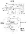
- the quad comparator 80 of sense amplifier 25 is shown in FIG. 3, and an exemplary input signal and logic outputs of the comparator are illustrated in FIG. 4.
- the comparator has two comparator pairs comprising sensing target comparators 150 and AGC target comparators 151.
- the logic outputs L1 and L2 (upper and lower, respectively) of the sensing target comparators are used by the microprocessor as valid sense input signals.
- the logical "OR" (L3, either positive or negative) of the AGC target comparators is used by the microprocessor to evaluate the need for increasing or decreasing the AGC amplifier gain.
- the sensing targets represent a sensing threshold, and the AGC targets represent a sensed signal peak amplitude target.
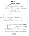
- the microprocesor 68 seeks to maintain the gain in such a way that the peak of the signal in the QRS complex approximately crosses the AGC target, as shown in FIG. 5.
- Such gain maintenance is achieved in the following manner. Any signal that crosses the sensing targets is considered to be a sense event. If a sense event occurs in a cardiac cycle, then sometime after it is sensed (which may, for example, occur during the refractory period, although the precise time is not significant) a flag is checked which indicates whether or not the AGC target was crossed by that sense event. If the AGC target was crossed, it is an indication that the gain is too high and should be decreased. If this occurs repetitively, the microprocessor decreases the gain. In the presently preferred embodiment, the gain is decreased by a certain percentage. As an alternative, however, the gain may be decreased by a fixed amount.
- the microprocessor also counts cycles in which sense events have occurred but there has been no crossing of the outer target. If this occurs predominantly the microprocessor recognizes that the gain is too low and must be increased. Here again, the increase may be effected as a fixed percentage or a fixed amount.
Abstract
Description
- The present invention relates generally to implantable cardiac stimulators such as pacemakers, and more particularly to automatic gain control suitable for use with either single or dual chamber pacemakers.
- Implantation of a cardiac pacemaker has been a typical procedure of choice for treatment of bradycardia patients. The pacemaker pulse generator is implanted in a pouch beneath the skin in the patient's chest and delivers electrical impulses to electrodes positioned at the patient's heart via one or more catheter leads, to stimulate the heart to beat at a desired rate in the normal sinus range.
- According to the present invention, the sense amplifier of the cardiac stimulator is provided with automatic gain control (AGC) as well as bandpass filtering and comparison of sensed signal (sensed event) amplitudes against selected target levels in a system and method for detecting cardiac events. Interactions between gain and pacing are utilized in a manner not found in prior art techniques employed to detect and treat cardiac events.
- The AGC amplifier includes an amplifier section having a gain that may be altered as often as necessary to maintain a set of predefined conditions, and a dual set of comparators to convert the processed analog information into digital information to be used by a microprocessor for making decisions about the need for changes in the gain of the amplifier and sensing activity.
- The above and still further objects, features and attendant advantages of the present invention will become apparent from a consideration of the following detailed description of a presently preferred embodiment, taken in conjunction with the accompanying drawings, in which:
- FIG. 1 is a block circuit diagram of the therapy generator of an implantable single chamber cardiac stimulator, utilizing a sense amplifier having AGC according to the presently preferred embodiment;
- FIG. 2 is a more detailed circuit diagram of the microprocessor and sense amplifier portion of the pulse generator circuit of FIG. 1;
- FIG. 3 is a schematic circuit diagram of the quad comparator section of the sense amplifier; and
- FIGS. 4 and 5 are waveforms useful for describing the operation of the sense amplifier according to the presently preferred embodiment.
- The block diagram of FIG. 1 is illustrating the circuitry for a single chamber pacemaker. It would only be necessary to create a second channel including a pacing section, analog rate limiter and sense amplifier to form a dual chamber pacemaker employing the subject AGC.
- The pulse generator (FIG. 1) unit of the stimulator is adapted to detect preselected aspects of the patient's cardiac activity, and to respond by generating and managing the delivery of pacing therapies. It will be evident, then, that despite its name the pulse generator does more than simply generate pulses in that the generator incorporates circuitry for sensing cardiac activity. Among other things, the generator has a self-contained power source, and is assembled and housed in a metal case which is inert to body tissue and fluids. Lead/electrode assemblies for use in sensing cardiac activity and delivering the pacing impulses to the patient's heart are connectable to the pulse generator. Together, then the pulse generator and the lead/electrode assemblies constitute the cardiac pacemaker.
- The pulse generator includes a digital control section for storing and executing software instructions and for storing and processing the data for all digital functions of the device (aside from those functions which, for purposes of conserving memory capacity, are readily consigned to an external programmer unit). Digital functions of the device may include the physician-programmable aspects, such as provision for programming rate output pulse width, or amplitude and, as well, the various processing, timing, switching, control and other functions which need not be decribed here inasmuch as they are not essential to an understanding of the present invention.
- The pulse generator also includes an analog system portion for functions including those of the present invention involving monitoring of the patient's ECG signal information over each cardiac cycle and enhancing that signal information while reducing noise and other interference through signal filtering and automatic gain control. Other analog functions of the generator include developing the respective impulse waveforms to be delivered for the pacing, transmitting data between the device and external units such as the programmer and transtelephonic monitoring equipment, and protecting against overloads. Also included are the battery cells and voltage regulation and for supplying power to the other sections of the overall pacemaker.
- With reference now to FIG. 1, a central microprocessor and associated
memory section 10 of the pulse generator processes and stores the data for rates, pulse widths, amplitudes, refractory periods, and other features. Bidirectionally coupled to microprocessor/memory section 10 is a programming anddata transmission section 14 for transmitting data to and from the external programmer and/or to receiving and monitoring equipment, via theantenna 17. Acrystal oscillator 20 is electrically coupled tosection 10 to provide precise timing signals for system operation. Areed switch 22 allows limited external control by means of placing an external magnet (not shown) in proximity to the switch for actuation thereof. - A
sense amplifier section 25 of the present invention, described in detail below, is coupled to the microprocessor/memory section 10 to furnish electrogram signal information and to receive control signals from the microprocessor. The sense amplifier also supplies electrogram signal information directly todata transmission section 14 for telemetry to the external monitoring equipment. A quad comparator withinsense amplifier 25 serves as the link to convert electrogram, sense signal information from sensing electrode(s) (not shown) attached to the patient's heart into digital information for use by the microprocessor. Themicroprocessor 10 is disposed in the feedback loop of thesense amplifier 25 for automatic gain control. - The
sense amplifier 25 enhances the electrogram signals. Preferably, thesense amplifier 25 has a range of gain of the order of at least 8:1. As will be explained in more detail below, AGC with bandpass filtering is employed to provide the function of reducing the amplitude of signals outside the frequency band of interest. - A
pacing section 31 in the pulse generator includes a voltage multiplier and output section (neither of which is shown and both of which are conventional). The multiplier scales up the regulated supply voltage frompower source section 28 by multiples of one half, one, one and one half, two or three. The output section provides output switching from this scaled voltage to deliver pacing stimuli to the patient's heart via the pacing electrodes (not shown) under the control of themicroprocessor 10. An analograte limit circuit 35 controllably limits the pacing rate, to prevent pacemaker runaway in the event of failure of thecrystal oscillator circuit 20. Themicroprocessor 10 automatically disables therate limiter 35 whenever high rate pacing pulses are required to be delivered. -
Sense amplifier 25 and its relationship to themicroprocessor 10 are illustrated in greater detail in FIG. 2. The ECG waveform components detected by the sensing electrodes (not shown) are applied to an AGC amplifier 60 via aninput circuit 63. The gain of amplifier 60 is automatically controlled by afeedback loop 65 containing aportion 68 of the microprocessor/memory section 10 (Fig. 1). The electrogram signals processed by AGC amplifier 60 are further enhanced by a filter section 70 having a primary highgain bandpass amplifier 73 to amplify signals within the band. The output ofamplifier 73 is split and applied to separateamplifiers microprocessor portion 68. The output derived from amplifier and filter states 60 and 70 is applied to a quad comparator 80 (to be described in greater detail below with reference to Fig. 3), comprising a set ofsensing target comparators 82 and a set ofAGC target comparators - The system of Fig. 2 provides dual signal paths. The signal path through
amplifier 75 to thesensing target comparators 82 determines the level and the signal path throughamplifier 76 to theAGC target comparators 83 portion is part of the feedback loop that includes themicroprocessor 68, which determines the gain of AGC amplifier 60. A sensing margin is defined as the ratio of peak signal size at the inputs to sensingtarget comparators 82 and their respective sensing thresholds. A ratio greater than one must be chosen in order to avoid loss of sensing as a consequence of a reduction in signal amplitude. For example, the use of a 2-to-1 margin would mean that the signal amplitude would have to be reduced by one half to lose sensing. The goal of the AGC system is to maintain a preset sensing margin. For a given threshold level on the sensing comparator, this may be achieved by adjusting the gain of the AGC amplifier 60 so that the peak voltage seen by thesensing comparators 82 remains more or less constant. Themicroprocessor 68 samples the output of theAGC comparators 83 on a cycle by cycle basis. In essence, if the waveform peak (see fig. 4) exceeds the threshold of the AGC detector, themicroprocessor 68 will reduce the gain a small amount. If the waveform peak (see Fig. 4) does not exceed the threshold of the AGC detector, the microprocessor will increase the gain a small amount (the increase/decrease decision process will be discussed in more detail later). - The bandpass of the signal path to the sensing comparator is shaped so that frequencies below 25 Hz are attentuated. This gives the desirable effect of attenuating the lower frequency T-wave relative to the QRS complex.
- The
quad comparator 80 ofsense amplifier 25 is shown in FIG. 3, and an exemplary input signal and logic outputs of the comparator are illustrated in FIG. 4. The comparator has two comparator pairs comprisingsensing target comparators 150 andAGC target comparators 151. The logic outputs L₁ and L₂ (upper and lower, respectively) of the sensing target comparators are used by the microprocessor as valid sense input signals. The logical "OR" (L₃, either positive or negative) of the AGC target comparators is used by the microprocessor to evaluate the need for increasing or decreasing the AGC amplifier gain. The sensing targets represent a sensing threshold, and the AGC targets represent a sensed signal peak amplitude target. - By way of an example of operation, in the presence of a QRS complex which is being monitored by the sense amplifier with its sensing and AGC targets, the
microprocesor 68 seeks to maintain the gain in such a way that the peak of the signal in the QRS complex approximately crosses the AGC target, as shown in FIG. 5. Such gain maintenance is achieved in the following manner. Any signal that crosses the sensing targets is considered to be a sense event. If a sense event occurs in a cardiac cycle, then sometime after it is sensed (which may, for example, occur during the refractory period, although the precise time is not significant) a flag is checked which indicates whether or not the AGC target was crossed by that sense event. If the AGC target was crossed, it is an indication that the gain is too high and should be decreased. If this occurs repetitively, the microprocessor decreases the gain. In the presently preferred embodiment, the gain is decreased by a certain percentage. As an alternative, however, the gain may be decreased by a fixed amount. - The microprocessor also counts cycles in which sense events have occurred but there has been no crossing of the outer target. If this occurs predominantly the microprocessor recognizes that the gain is too low and must be increased. Here again, the increase may be effected as a fixed percentage or a fixed amount.
- With the above considerations in mind, the following AGC algorithms are implemented in the presently preferred embodiment of the invention (independently implemented for each chamber of dual chamber pacemaker):
- 1. The microprocessor uses a counter to accumulate comparator target crossings.
- 2. The counter is initialized to its middle value, 128. For any specific sensed cardiac event, if both the sense and AGC comparator targets are crossed, the counter is incremented by two. If only the sense comparator target is crossed, the counter is decremented by one. As sensed events are accumulated in the counter, if the counter overflows, the AGC gain is reduced by one step and the counter is reset to its middle value. If the counter underflows, the AGC gain is increased by one step and the counter is reset to its middle value. These values are representative, but the important fact is that incrementing is weighted more heavily than decrementing to bias towards gain reduction and prevent double sensing due to T-waves.
- 3. When the microprocessor detects noise the counter is reset to its middle value. This prevents noise signals from affecting the AGC gain.
- 4. In the special case of nearly 100% pacing where the intrinsic cardiac activity is less than the programmed pacing rate, the counter is caused to drift toward its middle value. Another counter accumulates cycle of pacemaker activity. Every 256 pacemaker cycles; if the AGC accumulator counter is greater than 128, it is decremented by one. If it is less than 128, it is incremented by one. This prevents occasional spurious events detected over long periods of time from causing changes in gain.
Claims (16)
means forming dual signal paths for receiving said electrical signals, one of said signal paths constituting means for determining a sensing point for the signal, and the other of the signal paths constituting feedback loop means for determining signal gain, and thereby, a sensing margin.
a microprocessor in said feedback loop means.
means for selectively adjusting said sensing margin.
means for programming said sensing means.
electrode means for sensing electrical activity of a patient's heart, and
processing means responsive to the sensed electrical activity for detecting cardiac events, including target means for establishing at least one reference level against which the amplitudes of predetermined sensed events are to be compared, gain control means for controllably varying the sensitivity of the processing means according to the amplitude of the sensed event relative to said at least one reference level.
sensing means for producing electrical signals representative of electrical activity of the heart indicative of rhythmic and arrhythmic contractions thereof, and
signal processing means responsive to the electrical signals for programmably controlling the margin of sensitivity of the apparatus.
a feedback loop for said amplifier means; and
a microprocessor in said feedback loop for varying said amplification according to preselected algorithms.
means for detecting electrical signals produced by the heart; and
amplifier means responsive to the detected signals and having dual signals paths for said detected signals, one of said paths having a feedback loop with means for automatically adjusting the gain of the amplifier means whereby the gain and threshold relationships between said dual signal paths maybe altered to produce variable sensing margins.
Applications Claiming Priority (2)
| Application Number | Priority Date | Filing Date | Title |
|---|---|---|---|
| US203493 | 1988-06-07 | ||
| US07/203,493 US4903699A (en) | 1988-06-07 | 1988-06-07 | Implantable cardiac stimulator with automatic gain control |
Publications (2)
| Publication Number | Publication Date |
|---|---|
| EP0349130A1 true EP0349130A1 (en) | 1990-01-03 |
| EP0349130B1 EP0349130B1 (en) | 1994-04-27 |
Family
ID=22754234
Family Applications (1)
| Application Number | Title | Priority Date | Filing Date |
|---|---|---|---|
| EP89305624A Expired - Lifetime EP0349130B1 (en) | 1988-06-07 | 1989-06-05 | Implantable cardiac stimulator with automatic gain control |
Country Status (5)
| Country | Link |
|---|---|
| US (1) | US4903699A (en) |
| EP (1) | EP0349130B1 (en) |
| JP (1) | JP2802510B2 (en) |
| CA (1) | CA1327232C (en) |
| DE (1) | DE68914891T2 (en) |
Cited By (5)
| Publication number | Priority date | Publication date | Assignee | Title |
|---|---|---|---|---|
| WO1996038200A1 (en) * | 1995-06-01 | 1996-12-05 | Ascher, Gilles | Method and device for heart stimulation in the presence of electromagnetic interference |
| WO1997006852A1 (en) * | 1995-08-14 | 1997-02-27 | Cardiac Pacemakers, Inc. | Slow gain control |
| US5658317A (en) * | 1995-08-14 | 1997-08-19 | Cardiac Pacemakers, Inc. | Threshold templating for digital AGC |
| US5891169A (en) * | 1994-07-30 | 1999-04-06 | Biotronik Mess- Und Therapiegeraete Gmbh | Method of processing signals characteristic of cardiac activity and an associated device |
| WO1999021612A1 (en) * | 1997-10-27 | 1999-05-06 | Medtronic, Inc. | Method and apparatus for automatically adjusting the sensitivity of cardiac sense amplifiers |
Families Citing this family (27)
| Publication number | Priority date | Publication date | Assignee | Title |
|---|---|---|---|---|
| US5226414A (en) * | 1991-07-24 | 1993-07-13 | Intermedics, Inc. | Implantable cardiac pacemaker with extended atrial sensing |
| US5374282A (en) * | 1991-10-31 | 1994-12-20 | Medtronic, Inc. | Automatic sensitivity adjust for cardiac pacemakers |
| US5395393A (en) * | 1991-11-01 | 1995-03-07 | Telectronics Pacing Systems, Inc. | Intracardiac electrogram sensing in an arrhythmia control system |
| US5690693A (en) * | 1995-06-07 | 1997-11-25 | Sulzer Intermedics Inc. | Transcutaneous energy transmission circuit for implantable medical device |
| US5702431A (en) * | 1995-06-07 | 1997-12-30 | Sulzer Intermedics Inc. | Enhanced transcutaneous recharging system for battery powered implantable medical device |
| US5722998A (en) * | 1995-06-07 | 1998-03-03 | Intermedics, Inc. | Apparatus and method for the control of an implantable medical device |
| US5620466A (en) * | 1995-08-14 | 1997-04-15 | Cardiac Pacemakers, Inc. | Digital AGC using separate gain control and threshold templating |
| US5713939A (en) * | 1996-09-16 | 1998-02-03 | Sulzer Intermedics Inc. | Data communication system for control of transcutaneous energy transmission to an implantable medical device |
| US5772692A (en) | 1996-10-29 | 1998-06-30 | Sulzer Intermedics Inc. | Implantable medical device with automatic adjustment to externally generated shocks |
| US5913880A (en) * | 1997-04-07 | 1999-06-22 | Vitatron Medical, B.V. | Pacemaker with automatic sensitivity adjustment |
| US5843133A (en) * | 1997-04-14 | 1998-12-01 | Sulzer Intermedics Inc. | Dynamic bandwidth control in an implantable medical cardiac stimulator |
| US5800466A (en) * | 1997-04-14 | 1998-09-01 | Sulzer Intermedics Inc. | Dynamic atrial detection sensitivity control in an implantable medical cardiac simulator |
| US5735881A (en) * | 1997-04-14 | 1998-04-07 | Sulzer Intermedics Inc. | Variable atrail blanking period in an implantable medical device |
| US5772691A (en) * | 1997-04-14 | 1998-06-30 | Sulzer Intermedics Inc. | Implantable cardiac stimulator with polarity detection for detecting ectopic beats |
| US5861009A (en) | 1997-10-21 | 1999-01-19 | Sulzer Intermedics, Inc. | Implantable cardiac stimulator with rate-adaptive T-wave detection |
| US5944744A (en) * | 1998-02-06 | 1999-08-31 | Sulzer Intermedics Inc. | Implantable cardiac stimulator with automatic electrogram profiling |
| US5957857A (en) * | 1998-05-07 | 1999-09-28 | Cardiac Pacemakers, Inc. | Apparatus and method for automatic sensing threshold determination in cardiac pacemakers |
| US6501990B1 (en) * | 1999-12-23 | 2002-12-31 | Cardiac Pacemakers, Inc. | Extendable and retractable lead having a snap-fit terminal connector |
| US6463334B1 (en) * | 1998-11-02 | 2002-10-08 | Cardiac Pacemakers, Inc. | Extendable and retractable lead |
| US6539259B1 (en) | 1999-07-15 | 2003-03-25 | Pacesetter, Inc. | System and method of automatically adjusting sensitivity in an implantable cardiac stimulation device |
| US6208899B1 (en) | 1999-09-15 | 2001-03-27 | Pacesetter, Inc. | Implantable cardioversion device with automatic filter control |
| US6418343B1 (en) * | 1999-10-01 | 2002-07-09 | Cardiac Pacemakers, Inc. | Method and apparatus for adjusting the sensing threshold of a cardiac rhythm management device |
| US6862476B2 (en) * | 2002-02-20 | 2005-03-01 | Pacesetter, Inc. | Implantable cardiac stimulation device having automatic sensitivity control and method |
| US7463926B1 (en) * | 2005-06-24 | 2008-12-09 | Pacesetter, Inc. | Automatic signal amplitude measurement system in the setting of abnormal rhythms |
| US7715906B2 (en) * | 2007-06-04 | 2010-05-11 | Medtronic, Inc. | Method and apparatus for detecting noise in an implantable medical device |
| US8214042B2 (en) | 2009-05-26 | 2012-07-03 | Boston Scientific Neuromodulation Corporation | Techniques for controlling charging of batteries in an external charger and an implantable medical device |
| US11097117B2 (en) | 2019-02-22 | 2021-08-24 | Medtronic, Inc. | Medical device and method for power reduction for arrhythmia detection |
Citations (2)
| Publication number | Priority date | Publication date | Assignee | Title |
|---|---|---|---|---|
| EP0253505A2 (en) * | 1986-06-17 | 1988-01-20 | Intermedics, Inc. | Cardiac stimulator |
| DE3739014A1 (en) * | 1986-11-18 | 1988-05-19 | Mirowski Mieczyslaw | SYSTEM AND METHOD FOR THE CARDIO VERSION AND FOR PACEMAKER SERVICES |
Family Cites Families (6)
| Publication number | Priority date | Publication date | Assignee | Title |
|---|---|---|---|---|
| US4000461A (en) * | 1973-10-04 | 1976-12-28 | Textronix, Inc. | R-wave detector |
| US4312354A (en) * | 1980-02-04 | 1982-01-26 | Arco Medical Products Company | Pacemaker with circuit for pulse width modulating stimulus pulses in accordance with programmed parameter control states |
| US4364396A (en) * | 1981-06-15 | 1982-12-21 | Medtronic, Inc. | Circuit and method for measuring PSA output and energy |
| US4766902A (en) * | 1986-06-04 | 1988-08-30 | Telectronics N.V. | Automatic sensitivity control for cardiac pacer |
| US4768511A (en) * | 1986-07-10 | 1988-09-06 | Telectronics N.V. | Automatic sensitivity control for implantable cardiac pacemakers |
| US4708144A (en) * | 1986-10-06 | 1987-11-24 | Telectronics N.V. | Automatic sensitivity control for a pacemaker |
-
1988
- 1988-06-07 US US07/203,493 patent/US4903699A/en not_active Expired - Lifetime
-
1989
- 1989-04-12 CA CA000596531A patent/CA1327232C/en not_active Expired - Fee Related
- 1989-06-05 EP EP89305624A patent/EP0349130B1/en not_active Expired - Lifetime
- 1989-06-05 JP JP1142863A patent/JP2802510B2/en not_active Expired - Lifetime
- 1989-06-05 DE DE68914891T patent/DE68914891T2/en not_active Expired - Fee Related
Patent Citations (2)
| Publication number | Priority date | Publication date | Assignee | Title |
|---|---|---|---|---|
| EP0253505A2 (en) * | 1986-06-17 | 1988-01-20 | Intermedics, Inc. | Cardiac stimulator |
| DE3739014A1 (en) * | 1986-11-18 | 1988-05-19 | Mirowski Mieczyslaw | SYSTEM AND METHOD FOR THE CARDIO VERSION AND FOR PACEMAKER SERVICES |
Cited By (7)
| Publication number | Priority date | Publication date | Assignee | Title |
|---|---|---|---|---|
| US5891169A (en) * | 1994-07-30 | 1999-04-06 | Biotronik Mess- Und Therapiegeraete Gmbh | Method of processing signals characteristic of cardiac activity and an associated device |
| WO1996038200A1 (en) * | 1995-06-01 | 1996-12-05 | Ascher, Gilles | Method and device for heart stimulation in the presence of electromagnetic interference |
| FR2734731A1 (en) * | 1995-06-01 | 1996-12-06 | Christian Mounier | METHOD AND DEVICE FOR CARDIAC STIMULATION IN THE PRESENCE OF ELECTROMAGNETIC INTERFERENCE |
| WO1997006852A1 (en) * | 1995-08-14 | 1997-02-27 | Cardiac Pacemakers, Inc. | Slow gain control |
| US5658317A (en) * | 1995-08-14 | 1997-08-19 | Cardiac Pacemakers, Inc. | Threshold templating for digital AGC |
| US5662688A (en) * | 1995-08-14 | 1997-09-02 | Cardiac Pacemakers, Inc. | Slow gain control |
| WO1999021612A1 (en) * | 1997-10-27 | 1999-05-06 | Medtronic, Inc. | Method and apparatus for automatically adjusting the sensitivity of cardiac sense amplifiers |
Also Published As
| Publication number | Publication date |
|---|---|
| DE68914891T2 (en) | 1994-08-18 |
| EP0349130B1 (en) | 1994-04-27 |
| JPH0229271A (en) | 1990-01-31 |
| DE68914891D1 (en) | 1994-06-01 |
| CA1327232C (en) | 1994-02-22 |
| US4903699A (en) | 1990-02-27 |
| JP2802510B2 (en) | 1998-09-24 |
Similar Documents
| Publication | Publication Date | Title |
|---|---|---|
| US4903699A (en) | Implantable cardiac stimulator with automatic gain control | |
| US4880004A (en) | Implantable cardiac stimulator with automatic gain control and bandpass filtering in feedback loop | |
| US5549649A (en) | Programmable pacemaker including an atrial rate filter for deriving a filtered atrial rate used for switching pacing modes | |
| US5873894A (en) | Diagnostic test protocol in an implantable medical device | |
| EP0744190B1 (en) | Implantable antitachycardia stimulation device | |
| US8055342B2 (en) | Method and apparatus for adjusting the sensing threshold of a cardiac rhythm management device | |
| US4967746A (en) | Dual chamber pacemaker with adjustable blanking and V-A extension | |
| JP4633780B2 (en) | Implantable heart stimulator with safety noise mode | |
| EP1509280B1 (en) | Implantable medical device with autosensitivity algorithm for controlling sensing of cardiac signals | |
| EP1051223B1 (en) | System for inducing tachycardia utilizing near-field wave sensing | |
| EP1620177B1 (en) | Dynamic pacing interval extension for detection of intrinsic ventricular activity | |
| WO1999065565A9 (en) | Automatic threshold sensitivity adjustment for cardiac rhythm management devices | |
| US8126550B2 (en) | Methods and devices involving automatic atrial blanking | |
| US6128533A (en) | Pacemaker with automatic PVARP adjustment during automatic mode switching | |
| US5899929A (en) | System for inducing tachycardia utilizing near field T-wave sensing | |
| US7079891B1 (en) | System and method for providing cardioversion therapy and overdrive pacing using an implantable cardiac stimulation device | |
| US7113822B1 (en) | System and method for providing cardioversion therapy and overdrive pacing using an implantable cardiac stimulation device | |
| US7308306B1 (en) | System and method for dynamic ventricular overdrive pacing | |
| US6052621A (en) | System and method for inducing tachycardia | |
| EP0616819B1 (en) | Rate-responsive pacemaker | |
| US7474921B1 (en) | Adjustable overdrive pacing | |
| US7133719B1 (en) | Adjustable overdrive pacing | |
| US7133721B1 (en) | Adjustable overdrive pacing | |
| WO2005099815A1 (en) | Dynamic pacing interval extension for detection of intrinsic ventricular activity | |
| US8233983B2 (en) | Implantable heart stimulator and method for operation thereof |
Legal Events
| Date | Code | Title | Description |
|---|---|---|---|
| PUAI | Public reference made under article 153(3) epc to a published international application that has entered the european phase |
Free format text: ORIGINAL CODE: 0009012 |
|
| AK | Designated contracting states |
Kind code of ref document: A1 Designated state(s): CH DE FR GB IT LI NL SE |
|
| 17P | Request for examination filed |
Effective date: 19900125 |
|
| 17Q | First examination report despatched |
Effective date: 19920624 |
|
| GRAA | (expected) grant |
Free format text: ORIGINAL CODE: 0009210 |
|
| AK | Designated contracting states |
Kind code of ref document: B1 Designated state(s): CH DE FR GB IT LI NL SE |
|
| REF | Corresponds to: |
Ref document number: 68914891 Country of ref document: DE Date of ref document: 19940601 |
|
| ITF | It: translation for a ep patent filed |
Owner name: SOCIETA' ITALIANA BREVETTI S.P.A. |
|
| ET | Fr: translation filed | ||
| EAL | Se: european patent in force in sweden |
Ref document number: 89305624.2 |
|
| PLBI | Opposition filed |
Free format text: ORIGINAL CODE: 0009260 |
|
| 26 | Opposition filed |
Opponent name: BIOTRONIK MESS- UND THERAPIEGERAETE GMBH & CO INGE Effective date: 19950126 |
|
| NLR1 | Nl: opposition has been filed with the epo |
Opponent name: BIOTRONIK MESS-UND THERAPIEGERATE GMBH & CO ING.BU |
|
| PLBN | Opposition rejected |
Free format text: ORIGINAL CODE: 0009273 |
|
| STAA | Information on the status of an ep patent application or granted ep patent |
Free format text: STATUS: OPPOSITION REJECTED |
|
| 27O | Opposition rejected |
Effective date: 19951004 |
|
| NLR2 | Nl: decision of opposition | ||
| PGFP | Annual fee paid to national office [announced via postgrant information from national office to epo] |
Ref country code: FR Payment date: 20010517 Year of fee payment: 13 |
|
| PGFP | Annual fee paid to national office [announced via postgrant information from national office to epo] |
Ref country code: GB Payment date: 20010521 Year of fee payment: 13 Ref country code: CH Payment date: 20010521 Year of fee payment: 13 |
|
| PGFP | Annual fee paid to national office [announced via postgrant information from national office to epo] |
Ref country code: NL Payment date: 20010522 Year of fee payment: 13 |
|
| PGFP | Annual fee paid to national office [announced via postgrant information from national office to epo] |
Ref country code: DE Payment date: 20010523 Year of fee payment: 13 |
|
| PGFP | Annual fee paid to national office [announced via postgrant information from national office to epo] |
Ref country code: SE Payment date: 20010531 Year of fee payment: 13 |
|
| REG | Reference to a national code |
Ref country code: GB Ref legal event code: IF02 |
|
| PG25 | Lapsed in a contracting state [announced via postgrant information from national office to epo] |
Ref country code: GB Free format text: LAPSE BECAUSE OF NON-PAYMENT OF DUE FEES Effective date: 20020605 |
|
| PG25 | Lapsed in a contracting state [announced via postgrant information from national office to epo] |
Ref country code: SE Free format text: LAPSE BECAUSE OF NON-PAYMENT OF DUE FEES Effective date: 20020606 |
|
| PG25 | Lapsed in a contracting state [announced via postgrant information from national office to epo] |
Ref country code: LI Free format text: LAPSE BECAUSE OF NON-PAYMENT OF DUE FEES Effective date: 20020630 Ref country code: CH Free format text: LAPSE BECAUSE OF NON-PAYMENT OF DUE FEES Effective date: 20020630 |
|
| PG25 | Lapsed in a contracting state [announced via postgrant information from national office to epo] |
Ref country code: NL Free format text: LAPSE BECAUSE OF NON-PAYMENT OF DUE FEES Effective date: 20030101 Ref country code: DE Free format text: LAPSE BECAUSE OF NON-PAYMENT OF DUE FEES Effective date: 20030101 |
|
| GBPC | Gb: european patent ceased through non-payment of renewal fee |
Effective date: 20020605 |
|
| EUG | Se: european patent has lapsed | ||
| REG | Reference to a national code |
Ref country code: CH Ref legal event code: PL |
|
| PG25 | Lapsed in a contracting state [announced via postgrant information from national office to epo] |
Ref country code: FR Free format text: LAPSE BECAUSE OF NON-PAYMENT OF DUE FEES Effective date: 20030228 |
|
| NLV4 | Nl: lapsed or anulled due to non-payment of the annual fee |
Effective date: 20030101 |
|
| REG | Reference to a national code |
Ref country code: FR Ref legal event code: ST |
|
| PG25 | Lapsed in a contracting state [announced via postgrant information from national office to epo] |
Ref country code: IT Free format text: LAPSE BECAUSE OF NON-PAYMENT OF DUE FEES;WARNING: LAPSES OF ITALIAN PATENTS WITH EFFECTIVE DATE BEFORE 2007 MAY HAVE OCCURRED AT ANY TIME BEFORE 2007. THE CORRECT EFFECTIVE DATE MAY BE DIFFERENT FROM THE ONE RECORDED. Effective date: 20050605 |