EP0348983A2 - Method of charging and discharging battery and power source apparatus adopting the same - Google Patents
Method of charging and discharging battery and power source apparatus adopting the same Download PDFInfo
- Publication number
- EP0348983A2 EP0348983A2 EP89111880A EP89111880A EP0348983A2 EP 0348983 A2 EP0348983 A2 EP 0348983A2 EP 89111880 A EP89111880 A EP 89111880A EP 89111880 A EP89111880 A EP 89111880A EP 0348983 A2 EP0348983 A2 EP 0348983A2
- Authority
- EP
- European Patent Office
- Prior art keywords
- battery
- battery blocks
- blocks
- boosting coil
- block
- Prior art date
- Legal status (The legal status is an assumption and is not a legal conclusion. Google has not performed a legal analysis and makes no representation as to the accuracy of the status listed.)
- Granted
Links
Images


Classifications
-
- H—ELECTRICITY
- H01—ELECTRIC ELEMENTS
- H01M—PROCESSES OR MEANS, e.g. BATTERIES, FOR THE DIRECT CONVERSION OF CHEMICAL ENERGY INTO ELECTRICAL ENERGY
- H01M10/00—Secondary cells; Manufacture thereof
- H01M10/42—Methods or arrangements for servicing or maintenance of secondary cells or secondary half-cells
- H01M10/44—Methods for charging or discharging
- H01M10/441—Methods for charging or discharging for several batteries or cells simultaneously or sequentially
-
- B—PERFORMING OPERATIONS; TRANSPORTING
- B60—VEHICLES IN GENERAL
- B60L—PROPULSION OF ELECTRICALLY-PROPELLED VEHICLES; SUPPLYING ELECTRIC POWER FOR AUXILIARY EQUIPMENT OF ELECTRICALLY-PROPELLED VEHICLES; ELECTRODYNAMIC BRAKE SYSTEMS FOR VEHICLES IN GENERAL; MAGNETIC SUSPENSION OR LEVITATION FOR VEHICLES; MONITORING OPERATING VARIABLES OF ELECTRICALLY-PROPELLED VEHICLES; ELECTRIC SAFETY DEVICES FOR ELECTRICALLY-PROPELLED VEHICLES
- B60L53/00—Methods of charging batteries, specially adapted for electric vehicles; Charging stations or on-board charging equipment therefor; Exchange of energy storage elements in electric vehicles
- B60L53/10—Methods of charging batteries, specially adapted for electric vehicles; Charging stations or on-board charging equipment therefor; Exchange of energy storage elements in electric vehicles characterised by the energy transfer between the charging station and the vehicle
- B60L53/14—Conductive energy transfer
-
- B—PERFORMING OPERATIONS; TRANSPORTING
- B60—VEHICLES IN GENERAL
- B60L—PROPULSION OF ELECTRICALLY-PROPELLED VEHICLES; SUPPLYING ELECTRIC POWER FOR AUXILIARY EQUIPMENT OF ELECTRICALLY-PROPELLED VEHICLES; ELECTRODYNAMIC BRAKE SYSTEMS FOR VEHICLES IN GENERAL; MAGNETIC SUSPENSION OR LEVITATION FOR VEHICLES; MONITORING OPERATING VARIABLES OF ELECTRICALLY-PROPELLED VEHICLES; ELECTRIC SAFETY DEVICES FOR ELECTRICALLY-PROPELLED VEHICLES
- B60L58/00—Methods or circuit arrangements for monitoring or controlling batteries or fuel cells, specially adapted for electric vehicles
- B60L58/10—Methods or circuit arrangements for monitoring or controlling batteries or fuel cells, specially adapted for electric vehicles for monitoring or controlling batteries
- B60L58/18—Methods or circuit arrangements for monitoring or controlling batteries or fuel cells, specially adapted for electric vehicles for monitoring or controlling batteries of two or more battery modules
- B60L58/22—Balancing the charge of battery modules
-
- H—ELECTRICITY
- H02—GENERATION; CONVERSION OR DISTRIBUTION OF ELECTRIC POWER
- H02J—CIRCUIT ARRANGEMENTS OR SYSTEMS FOR SUPPLYING OR DISTRIBUTING ELECTRIC POWER; SYSTEMS FOR STORING ELECTRIC ENERGY
- H02J7/00—Circuit arrangements for charging or depolarising batteries or for supplying loads from batteries
- H02J7/0013—Circuit arrangements for charging or depolarising batteries or for supplying loads from batteries acting upon several batteries simultaneously or sequentially
- H02J7/0014—Circuits for equalisation of charge between batteries
- H02J7/0018—Circuits for equalisation of charge between batteries using separate charge circuits
-
- Y—GENERAL TAGGING OF NEW TECHNOLOGICAL DEVELOPMENTS; GENERAL TAGGING OF CROSS-SECTIONAL TECHNOLOGIES SPANNING OVER SEVERAL SECTIONS OF THE IPC; TECHNICAL SUBJECTS COVERED BY FORMER USPC CROSS-REFERENCE ART COLLECTIONS [XRACs] AND DIGESTS
- Y02—TECHNOLOGIES OR APPLICATIONS FOR MITIGATION OR ADAPTATION AGAINST CLIMATE CHANGE
- Y02E—REDUCTION OF GREENHOUSE GAS [GHG] EMISSIONS, RELATED TO ENERGY GENERATION, TRANSMISSION OR DISTRIBUTION
- Y02E60/00—Enabling technologies; Technologies with a potential or indirect contribution to GHG emissions mitigation
- Y02E60/10—Energy storage using batteries
-
- Y—GENERAL TAGGING OF NEW TECHNOLOGICAL DEVELOPMENTS; GENERAL TAGGING OF CROSS-SECTIONAL TECHNOLOGIES SPANNING OVER SEVERAL SECTIONS OF THE IPC; TECHNICAL SUBJECTS COVERED BY FORMER USPC CROSS-REFERENCE ART COLLECTIONS [XRACs] AND DIGESTS
- Y02—TECHNOLOGIES OR APPLICATIONS FOR MITIGATION OR ADAPTATION AGAINST CLIMATE CHANGE
- Y02T—CLIMATE CHANGE MITIGATION TECHNOLOGIES RELATED TO TRANSPORTATION
- Y02T10/00—Road transport of goods or passengers
- Y02T10/60—Other road transportation technologies with climate change mitigation effect
- Y02T10/70—Energy storage systems for electromobility, e.g. batteries
-
- Y—GENERAL TAGGING OF NEW TECHNOLOGICAL DEVELOPMENTS; GENERAL TAGGING OF CROSS-SECTIONAL TECHNOLOGIES SPANNING OVER SEVERAL SECTIONS OF THE IPC; TECHNICAL SUBJECTS COVERED BY FORMER USPC CROSS-REFERENCE ART COLLECTIONS [XRACs] AND DIGESTS
- Y02—TECHNOLOGIES OR APPLICATIONS FOR MITIGATION OR ADAPTATION AGAINST CLIMATE CHANGE
- Y02T—CLIMATE CHANGE MITIGATION TECHNOLOGIES RELATED TO TRANSPORTATION
- Y02T10/00—Road transport of goods or passengers
- Y02T10/60—Other road transportation technologies with climate change mitigation effect
- Y02T10/7072—Electromobility specific charging systems or methods for batteries, ultracapacitors, supercapacitors or double-layer capacitors
-
- Y—GENERAL TAGGING OF NEW TECHNOLOGICAL DEVELOPMENTS; GENERAL TAGGING OF CROSS-SECTIONAL TECHNOLOGIES SPANNING OVER SEVERAL SECTIONS OF THE IPC; TECHNICAL SUBJECTS COVERED BY FORMER USPC CROSS-REFERENCE ART COLLECTIONS [XRACs] AND DIGESTS
- Y02—TECHNOLOGIES OR APPLICATIONS FOR MITIGATION OR ADAPTATION AGAINST CLIMATE CHANGE
- Y02T—CLIMATE CHANGE MITIGATION TECHNOLOGIES RELATED TO TRANSPORTATION
- Y02T90/00—Enabling technologies or technologies with a potential or indirect contribution to GHG emissions mitigation
- Y02T90/10—Technologies relating to charging of electric vehicles
- Y02T90/14—Plug-in electric vehicles
-
- Y—GENERAL TAGGING OF NEW TECHNOLOGICAL DEVELOPMENTS; GENERAL TAGGING OF CROSS-SECTIONAL TECHNOLOGIES SPANNING OVER SEVERAL SECTIONS OF THE IPC; TECHNICAL SUBJECTS COVERED BY FORMER USPC CROSS-REFERENCE ART COLLECTIONS [XRACs] AND DIGESTS
- Y10—TECHNICAL SUBJECTS COVERED BY FORMER USPC
- Y10S—TECHNICAL SUBJECTS COVERED BY FORMER USPC CROSS-REFERENCE ART COLLECTIONS [XRACs] AND DIGESTS
- Y10S320/00—Electricity: battery or capacitor charging or discharging
- Y10S320/34—Robot, hybrid, recreational or emergency vehicle
Definitions
- the present invention relates to a method of charging and discharging a battery having a plurality of electrochemical cells which dissolve an active material from the electrodes into the electrolyte during the discharging process and deposit the active material on the surfaces of the electrodes during the charging process and an apparatus adopting this method. More particularly, the present invention relates to such a method and apparatus for achieving full discharge in order to equalize the electrodes.
- a metal-halogen battery such as a zinc-bromine battery having a plurality of electrochemical cells which dissolve an active material from the electrodes into the electrolyte during the discharging process and deposit the active material on the surfaces of the electrodes in the charging process.
- a battery of this system is disclosed in, for example, Japanese Patent Laid-Open No. 132775/1981. The prior art will be explained in the following with reference to Fig. 12.
- the reference numeral 112 represents a container of a electrochemical cell which is a structural unit of a battery.
- the container 112 accommodates a negative electrode 114, a positive electrode 116 and a separator film 118 for separating the negative electrode 114 and the positive electrode 116 from each other.
- an electrolyte on the negative electrode side is supplied from an electrolyte tank 122 through a pipe 120 and a pump 124, and to the positive electrode 116, an electrolyte on the positive electrode side is supplied from an electrolyte tank 130 through a pipe 128 and a pump 126.
- the electrolyte tank 130 on the positive electrode side may accommodate a complex tank (not shown) which stores bromine in the form of a complex.
- the positive electrode 116 and the negative electrode 114 are composed of a conductive resin material such as carbon plastic for the purpose of lightening the weight.
- the Zn2+ ions in the electrolyte are deposited on the negative electrode 114 as Zn, and Br ⁇ ions are changed into Br2 on the side of the positive electrode 116 and dispersed in the electrolyte in the form of a complex.
- Zn deposited on the negative electrode 114 dissolves in the electrolyte in the form of Zn2+ ions, and Br2 dissolves in the electrolyte in the form of Br ⁇ ions.
- a battery practically used is composed of a multiplicity of such cells laminated in series in order to obtain a desired output voltage.
- the difference in the amount of Zn deposit namely, the difference in the amount of charge increases with the lapse of time whether it is in operation or out of operation, as indicated by the solid line in Fig. 7.
- the total capacity and the voltage of the battery are reduced.
- the battery before charge has been fully discharged so as to dissolve the total amount of Zn deposited on the negative electrodes in the electrolyte.
- the battery is divided into a plurality of battery blocks and the discharge current is increased for achieving full discharge in any given block in comparison with the other blocks in order to achieve the full discharge of the battery in operation.
- Japanese Patent Laid-Open No. 49577/1985 discloses a method of achieving the full discharge of a give one battery block in the same structure by feeding from the battery block to an auxiliary battery.
- the present invention provides a method of charging and discharging a battery having a plurality of electrochemical cells which dissolve an active material such as zinc ions from the electrodes into the electrolyte in the discharging process and deposit the active material on the surfaces of the negative electrodes in the charging process, the method comprising: preparing a battery composed of a plurality of battery blocks each of which is composed of a plurality of the electrochemical cells connected in series to each other; providing a step of fully discharging any given battery block among the plurality of battery blocks by transferring the charges of the given battery block to at least one of the other battery blocks through a booster means; and repeating the step so that all the plurality of battery blocks subsequently experience at least one cycle of full discharge within a predetermined period of time.
- the present invention also provides a power source apparatus comprising: electrochemical cells for dissolving an active material from the electrodes into the electrolyte in the discharging process and depositing the active material on the surfaces of the electrodes in the charging process; battery blocks each of which is composed of a plurality of the electrochemical cells connected in series to each other; a battery composed of a plurality of the battery blocks connected to each other; a booster means which is connected to any given battery block among the plurality of battery blocks for raising the output voltage of the given battery block; a charge transfer passage for connecting the output side of the booster means to at least one of the other battery blocks; and a control circuit for controlling the boosting operation of the booster means and the charges transferred through the charge transfer passage; whereby each of the battery blocks experiences at least one cycle of full discharge within a predetermined period of time.
- the electric power remaining in the battery block which is to be fully discharged is transferred to another battery block through the booster means, so that full discharge for equalization is carried out without causing a loss of electric power.
- This method can be carried out while the battery is in operation, namely, while the battery supplies electric power to the load.
- This method can also be carried out while the whole battery is out of operation, because there is no loss of electric power.
- Figs. 1 and 2 show a first embodiment of an apparatus which adopts a method of charging and discharging a battery according to the present invention.
- Fig. 1 shows the structure of the apparatus in a state of charging the battery in order to store energy therein
- Fig. 2 shows the structure of the apparatus in a state of discharging the battery in order to drive the load.
- a charger 12 which is fed from a commercial power source 10 is connected to contactors 14 and 16.
- the contactors 14 and 16 have contacts A, B and C, D, respectively, which are switched from each other and connected to contacts X and Y, respectively.
- Battery blocks 18 and 20 are connected to the contactors 14 and 16, respectively. That is, the positive terminal of the battery block 18 is connected to the contact A of the contactor 14, the negative terminal of the battery block 18 and the positive terminal of the battery block 20 are connected to the contacts B and C, and the negative terminal of the battery block 20 is connected to the contact D.
- the AC power (generally 100 V or 200 V) supplied from the commercial power source 10 is converted into a predetermined DC power by the charger 12. If the contact X of the contactor 14 is connected to the contact A and the contact Y of the contactor 16 is connected to the contact D, a predetermined DC power is supplied to the battery blocks 18 and 20 which are connected in series to each other, thereby charging the battery blocks 18 and 20.
- a power converter 22 is connected to the contactors 14 and 16, and to the power converter 22 a load 24 such as a motor is connected, as shown in Fig. 2.
- the power of the battery block 18 is supplied to the load 24 through the power converter 22, while the power of the battery block 20 is supplied to the load 24 through the power converter 22 when the contact X of the contactor 14 is connected to the contact B and the contact Y of the contactor 16 is connected to the contact D.
- the power converter 22 is composed of a chopper, an inverter and the like, and supplies the DC power from the battery block 18 or 20 to the load 24 such as an induction motor in the form of a predetermined AC power.
- the apparatus is further provided with a booster circuit 25 as a booster means. That is, transistors 26 and 28 and diodes 30 and 32 are connected to the battery blocks 18 and 20.
- the collector of the transistor 26 is connected to the positive electrode side of the battery block 18, the emitter of the transistor 28 is connected to the negative electrode side of the battery block 20, and the connecting portion of the collector and the emitter of the transistors 26 and 28 is connected to the connecting portion of the battery blocks 18 and 20.
- the diodes 30 and 32 are disposed in such a manner as to prevent a short-circuit current from flowing from the positive electrode of the battery block 18 to the negative electrode of the battery block 20.
- the connecting point of the transistors 26 and 28 and the connecting point 34 of the diodes 30 and 32 are connected to the connecting portion of the battery blocks 18 and 20 through a boosting coil 36.
- the transistors 26 and 28 are turned on and off in accordance with a signal supplied from a control circuit 40 through a switch 38.
- the control circuit 40 includes a rectangular wave oscillator such as a multivibrator which is capable of adjusting a pulse width and pulse frequency and controls the on/off operation of the transistors 26 and 28.
- the battery blocks 18 and 20 are connected in series and a power which is adjusted to predetermined current and voltage is supplied thereto from the charger 12 so as to charge the battery as a whole.
- the contacts of the contactors 14 and 16 are switched so as to charge the other battery block solely. It is necessary to lower the voltage supplied to half the initial voltage simultaneously with the switching operation.
- the power is subsequently supplied from the battery blocks 18 and 20 to the load 24 through the power converter 22.
- full discharge for equalization of either of the battery blocks 18 and 20 is enabled by the following operation whether the battery blocks 18 or 20 is supplying a power to the load 24 or they are not operated.
- a rectangular wave signal is supplied from the control circuit 40 to either of the transistors 26 and 28 through the switch 38.
- the signals is supplied to the base of either of the transistors 26 and 28 so as to turn on and off the transistor.
- the power stored in the boosting circuit 36 raises the potential of the connecting point 34 of the diodes 30 and 32, and flows to the positive electrode side of the battery block 18 through the diode 30, thereby charging the battery block 18.
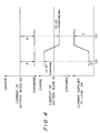
- Fig. 3 shows the state of the rectangular wave which is output from the control circuit 40, and the changes in the current values of the transistor 28, the diode 30 and the boosting coil 36 in accordance with the rectangular wave. It is understood from Fig. 3, that the current value of the transistor 28 gradually rises and when the current value becomes zero, a charge current flows to the battery block 18 through the diode 30.
- two battery blocks are provided and they are discharged alternately, but the number of battery blocks is not limited to two, and a combination of three battery blocks or more may be usable.
- N battery blocks are provided.
- a power is transferred from the n-th battery block to the n-1)-th battery block to fully discharge the n-th battery block. Repetitions of such full discharge on a predetermined cycle subsequently enables the full discharge of all the battery blocks.
- the timing for full discharge is independent of the state in which the battery supplies a power to the load. For example, when the contact X of the contactor 14 is connected to the contact A and the contact Y of the contactor 16 is connected to the contact C, as indicated by the solid lines in Fig. 2 and a power is supplied from the battery block 18 to the load 24 through the power converter 22, if a rectangular wave signal from the control circuit 40 is supplied to the base of the transistor 28 through the switch 38, the transistor 28 is turned on or off and the battery block 20 is discharged to supply a power to the battery block 18, as described above.
- the discharge current of the battery block 20 is set at the maximum possible value A ampere by, for example, adjusting the on-off period of the transistor 28. If the current supplied to the load 24 is as small as B ampere, as shown by a symbol (a) in Fig. 4, the current of a magnitude equivalent to the difference, namely, (A - B) ampere is supplied to the battery block 18 as a charge current.
- the electrolyte on the positive electrode side is common to the battery blocks 18 and 20
- the Br ⁇ ions dissolved reach the positive electrode of the battery block 18, receive the charge current and deposit in the electrolyte as Br2. Therefore, the concentration of Br ⁇ ions in the electrolyte is still 20%, in other words, the electrolyte is in the fully charged state.
- Zn on the electrode plate is dissolves into the electrolyte as Zn2+ ions in the battery block 20. Since the electrolyte on the negative electrode side is also common to the battery blocks 18 and 20, the Zn2+ ions dissolved reach the negative electrode of the battery block 18, receive the charge current and deposit on the electrode plate. In other words, on the negative electrode side, Zn on the electrode plate of the battery block 20 transfers onto the electrode plate of the battery block 18. Since the space between the electrode plates is generally much larger than the thickness of the layer of the deposited metal (plated layer), the deposition of Zn on the negative electrode in the battery block 18 is carried out without any obstacle. Accordingly, it is possible to fully discharge for equalization and complete dissolve Zn on the negative electrode plate even in the fully charged state.
- full discharge of a battery is possible irrespective of the state in which a power is supplied to the load and the charged state of a battery block, full discharge for equalization can be carried out at any given timing and even while the battery is out of operation.
- the charge current is detected by using a residual capacity meter for detecting the integrated value of charge and discharge current such as that described in, for example, Japanese Patent Laid-Open No. 28476/1981.
- the fully discharged state of either of the battery blocks by the above-described operation is also detected by detecting that the terminal voltage of the battery block becomes zero when the transistor is OFF.
- FIG. 5 Another embodiment of an apparatus of the present invention is shown in Fig. 5.
- This embodiment is provided with a voltage detection circuit 106 for detecting the terminal voltage of battery block 18 and the terminal voltage of the battery block 20.
- a signal from the control circuit 40 is supplied to the base of the transistor 26 or the transistor 28 in the same way as in the first embodiment, but the switch 38 provided between the control circuit 40 and the transistors 26 and 28 is controlled by a CPU 110 through an actuator 108.
- the values of the terminal voltage V18 of the battery block 18 and the terminal voltage V20 of the battery block 20 are first read by the voltage detection circuit 106. The values of V18 and V20 are compared with each other. If the terminal voltage V18 is larger than V20, it represents that the contact E of the switch 38 is closed and and a power is being transferred from the battery block 20 to the battery block 18. The terminal voltage V20 is then compared with the predetermined minimum voltage ( ⁇ 0 volt). This operation is repeated until V20 becomes smaller than the minimum value.
- the contacts of the switch 38 are switched from E to F. In this way, the transfer of the power from the battery block 20 to battery block 18 is finished, and the transfer of the power from the battery block 18 to battery block 20 is started in turn.
- V18 and V20 are compared with each other, since the contact F of the switch 38 is closed and a power is being transferred from the battery block 18 to the battery block 20, V20 is larger than V18.
- the terminal voltage V18 is then compared with the predetermined minimum voltage ( ⁇ 0 volt) When V18 becomes substantially 0 volt, the switch contacts are switched from F to E. Incidentally, it is possible to provide a predetermined suspension period in which both E and F are open immediately after V18 or V20 becomes substantially 0 volt and before the contacts are switched between E and F.
- the electrochemical cells of the battery blocks 18 and 20 are subsequently fully discharged, whereby all the electrochemical cells assume a uniform state free from deterioration. That is, it is possible to keep the amount of charge of each of the electrochemical cells constituting the battery blocks 18 and 20 uniform, as shown in Fig. 7.
- Such full discharge may be carried out not only in accordance with the detection of the terminal voltages of the battery blocks but also intermittently, for example, by the control of a timer.
- FIG. 8 Still another embodiment of an apparatus of the present invention is shown in Fig. 8. This embodiment is characterized in that a booster circuit 25A has a different structure from that of the booster circuit 25 in the first embodiment.
- One transistor 42 is adopted in place of the transistors 26 and 28 in the first embodiments.
- a signal from the control circuit 40 is supplied to the base of the transistor 42 in the same way as in the first embodiment.
- the collector and the emitter of the transistor 42 are connected to the switches 44 and 46, respectively. Therefore, if the switches 44 and 46 are connected as shown in Fig. 8, the transistor 42 constitutes a circuit for short-circuitting between the positive electrode and the negative electrode of the battery block 18. By turning on and off the transistor 42, the power remaining in the battery block 18 is transferred to the battery block 20. If the switches 44 and 46 are connected to the opposite side to the side shown in Fig. 8, the power in the battery block 20 is transferred to the battery block 18.
- a further embodiment of an apparatus of the present invention is shown in Fig. 9.
- the battery blocks 18 and 20 are disposed in parallel.
- a booster circuit 25B has a transistor 50, a boosting coil 52 and a diode 54 for transferring the power remaining in the battery block 20 to the battery block 18 and a transistor 56, a boosting coil 58 and a diode 60 for transferring a power from the battery block 18 to the battery block 20.
- the power in the battery block 20 is stored in the boosting coil 52 and then transferred to the battery block 18 through the diode 54 so as to be utilized for charging the battery block 18. If the transistor 56 is turned on and off, the power in the battery block 18 is transferred to the battery block 20.
- the diodes 62 and 64 prevent a power from flowing backward to the charger 12 during the above-described transfer of the power.
- the parallel arrangement of the battery blocks makes the control circuit slightly complicated, but brings about advantages such as a low terminal voltage and a small self discharge.
- FIG. 10 A modification of the fourth embodiment shown in Fig. 9 is shown in Fig. 10.
- the booster circuit 25 is replaced by a booster circuit 25C having a different structure.
- a transistor 70 is used in place of the transistors 50 and 56, a boosting coil 72 is used in place of the boosting coils 52 and 58 and a diode 74 is used in place of the diodes 54 and 60.
- this embodiment is provided with switches 76 and 78.
- the transfer of a power from the battery block 18 to the battery block 20 and the transfer of a power from the battery block 20 to the battery block 18 are switched from each other.
- the booster circuit 25B shown in Fig. 9 is replaced by a booster circuit 25D, and the boosting coils 52 and 58 are replaced by a boosting coil 80.
- the boosting coil 80 has a center tap 82, which is connected to a transistor 84.
- Switches 86 and 88 for bypassing the diodes 60 and 54 are provided, and by the change-over of the switches 86 and 88 the direction of the transfer of a power is switched.
- This embodiment also enables the transistors 50 and 56 and the boosting coils 52 and 58 to be replaced by one transistor and one boosting coil.
- a battery is divided into a plurality of battery blocks.
- a current flowing into a coil is rapidly changed by a switching element so as to raise the output voltage of one battery block.
- the power of the battery block is transferred to another battery block by utilizing the thus-raised voltage. This operation is subsequently repeated for each battery block.
- all the blocks are subsequently completely discharged for achieving the equalization of the amount of charge of each block.
Abstract
Description
- The present invention relates to a method of charging and discharging a battery having a plurality of electrochemical cells which dissolve an active material from the electrodes into the electrolyte during the discharging process and deposit the active material on the surfaces of the electrodes during the charging process and an apparatus adopting this method. More particularly, the present invention relates to such a method and apparatus for achieving full discharge in order to equalize the electrodes.
- In the apparatus such as an electric vehicle which supplies an electric power to the load by using a battery, it is very important in terms of the performance of the apparatus to enlarge the capacity and prolong the life of the battery.
- As a battery which is capable of effectively supplying a large capacity of electric power, a metal-halogen battery such as a zinc-bromine battery having a plurality of electrochemical cells which dissolve an active material from the electrodes into the electrolyte during the discharging process and deposit the active material on the surfaces of the electrodes in the charging process has been developed. A battery of this system is disclosed in, for example, Japanese Patent Laid-Open No. 132775/1981. The prior art will be explained in the following with reference to Fig. 12.
- In Fig. 12, the
reference numeral 112 represents a container of a electrochemical cell which is a structural unit of a battery. Thecontainer 112 accommodates anegative electrode 114, apositive electrode 116 and aseparator film 118 for separating thenegative electrode 114 and thepositive electrode 116 from each other. - To the
negative electrode 114, an electrolyte on the negative electrode side is supplied from anelectrolyte tank 122 through apipe 120 and apump 124, and to thepositive electrode 116, an electrolyte on the positive electrode side is supplied from anelectrolyte tank 130 through apipe 128 and apump 126. Theelectrolyte tank 130 on the positive electrode side may accommodate a complex tank (not shown) which stores bromine in the form of a complex. Thepositive electrode 116 and thenegative electrode 114 are composed of a conductive resin material such as carbon plastic for the purpose of lightening the weight. - In such a cell, during charging, the Zn²⁺ ions in the electrolyte are deposited on the
negative electrode 114 as Zn, and Br⁻ ions are changed into Br₂ on the side of thepositive electrode 116 and dispersed in the electrolyte in the form of a complex. On the other hand, during discharging, Zn deposited on thenegative electrode 114 dissolves in the electrolyte in the form of Zn²⁺ ions, and Br₂ dissolves in the electrolyte in the form of Br⁻ ions. A battery practically used is composed of a multiplicity of such cells laminated in series in order to obtain a desired output voltage. - In this case, it is only the
containers 112, thenegative electrodes 114, thepositive electrodes 116 and theseparator films 118 that are laminated as the cells, and thepipes electrolyte tanks pumps - In the above-described battery, the configurations of the negative electrodes and the positive electrodes and the natures of the separator films slightly differ with cells. For this reason, the natures of the cells are not exactly the same, which disadvantageously causes a difference in amount of self-discharge.
- Therefore, in a battery composed of a plurality of such cells connected in series, the difference in the amount of Zn deposit, namely, the difference in the amount of charge increases with the lapse of time whether it is in operation or out of operation, as indicated by the solid line in Fig. 7. As a result, the total capacity and the voltage of the battery are reduced.
- It is also known that not only is there a nonuniformity of the amount of Zn deposit between the cells, but also there is a difference in the amount of Zn deposited on the surface of the negative electrode in one cell depending on the locality, which may cause a trouble such as a breakage of the separator film due to the growth of dendrites during repetitions of charge and discharge.
- Conventionally, as a measure for eliminating the nonuniformity of the amount of Zn deposit and depositing Zn on the negative electrodes to a uniform thickness (hereinunder referred to as "equalization"), the battery before charge has been fully discharged so as to dissolve the total amount of Zn deposited on the negative electrodes in the electrolyte. According to a method disclosed in Japanese Patent Laid-Open No. 132775/1981, the battery is divided into a plurality of battery blocks and the discharge current is increased for achieving full discharge in any given block in comparison with the other blocks in order to achieve the full discharge of the battery in operation. Japanese Patent Laid-Open No. 49577/1985 discloses a method of achieving the full discharge of a give one battery block in the same structure by feeding from the battery block to an auxiliary battery.
- However, when these methods are applied to an electric vehicle, which generally travels a short distance per day, it is often the case that the full discharge is not achieved even in one battery block among all the blocks during operation of the battery, namely, between the completion of the charge of the battery and the initiation of the next charge.
- Accordingly, if the full discharge for equalization is carried out in all the blocks of the battery, a large capacity remains in the battery and since the electric power is consumed by the auxiliary equipment, it cannot afford a sufficiently large discharge current, so that a long time is required for realizing the full discharge, which makes it impossible to prevent the growth of dendrites.
- If the battery is continuously operated until the battery is sufficiently discharged in order to eliminate this problem, there is much risk of the battery dying during the operation and disabling the electric vehicle from running.
- As a usage of the battery, a method of not operating all the blocks equally but fully discharging the blocks one by one may be considered. This method, however, is unsuitable for practical use, because if a part of the blocks of the battery are discharged, the blocks lose the capacity of energy supply for running, thereby greatly reducing the output of the battery and the driving performance thereafter.
- Especially, in the case of an electric vehicle, since the capacity of the battery mounted thereon is limited, it is desirable that the maximum electric power is constantly supplied from all the blocks of the battery.
- Accordingly, it is an object of the present invention to eliminate the above-described problems in the prior art and to provide a method of charging and discharging a battery which is capable of enabling all the blocks of the battery to experience a cycle of full discharge and charge without any external charging source by transferring the charges of any given block other than the charges consumed by the load to another part of the battery so as to be stored therein and re-charging the given block with the stored charges.
- To achieve this aim, the present invention provides a method of charging and discharging a battery having a plurality of electrochemical cells which dissolve an active material such as zinc ions from the electrodes into the electrolyte in the discharging process and deposit the active material on the surfaces of the negative electrodes in the charging process, the method comprising: preparing a battery composed of a plurality of battery blocks each of which is composed of a plurality of the electrochemical cells connected in series to each other; providing a step of fully discharging any given battery block among the plurality of battery blocks by transferring the charges of the given battery block to at least one of the other battery blocks through a booster means; and repeating the step so that all the plurality of battery blocks subsequently experience at least one cycle of full discharge within a predetermined period of time.
- The present invention also provides a power source apparatus comprising: electrochemical cells for dissolving an active material from the electrodes into the electrolyte in the discharging process and depositing the active material on the surfaces of the electrodes in the charging process; battery blocks each of which is composed of a plurality of the electrochemical cells connected in series to each other; a battery composed of a plurality of the battery blocks connected to each other; a booster means which is connected to any given battery block among the plurality of battery blocks for raising the output voltage of the given battery block; a charge transfer passage for connecting the output side of the booster means to at least one of the other battery blocks; and a control circuit for controlling the boosting operation of the booster means and the charges transferred through the charge transfer passage; whereby each of the battery blocks experiences at least one cycle of full discharge within a predetermined period of time.
- According to the present invention, the electric power remaining in the battery block which is to be fully discharged is transferred to another battery block through the booster means, so that full discharge for equalization is carried out without causing a loss of electric power. This method can be carried out while the battery is in operation, namely, while the battery supplies electric power to the load. This method can also be carried out while the whole battery is out of operation, because there is no loss of electric power.
- In other words, it is possible to equalize the whole battery without changing the state of electric power by repeating the steps of "full discharge and charging with the electric power from another battery block" subsequently for each battery block while the battery is out of operation.
- The above and other objects, features and advantages of the present invention will become clear from the following description of the preferred embodiments thereof, taken in conjunction with the accompanying drawings.
-
- Fig. 1 shows the structure of a first embodiment of an apparatus which adopts a method of charging and discharging a battery according to the present invention, under the battery charging condition;
- Fig. 2 shows the structure of the first embodiment shown in Fig. 1, in the state of discharging the battery;
- Fig. 3 shows the waveforms of the voltage and the current at each point of the first embodiment shown in Fig. 1;
- Fig. 4 shows the charged and discharged states of battery blocks in the first embodiment shown in Fig. 1;
- Fig. 5 shows the structure of a second embodiment of an apparatus according to the present invention;
- Fig. 6 is a flow chart of the operation of a
CPU 110 in the second embodiment shown in Fig. 5; - Fig. 7 is a characteristic curve showing the charged state of each electrochemical cell in the second embodiment shown in Fig. 5;
- Fig. 8 shows the structure of a third embodiment of an apparatus according to the present invention;
- Fig. 9 shows the structure of a fourth embodiment of an apparatus according to the present invention;
- Fig. 10 shows the structure of a fifth embodiment of an apparatus according to the present invention;
- Fig. 11 shows the structure of a sixth embodiment of an apparatus according to the present invention; and
- Fig. 12 shows the structure of a metal-halogen battery in the prior art.
-
- The present invention will be explained hereinunder with reference to the accompanying drawings.
- Figs. 1 and 2 show a first embodiment of an apparatus which adopts a method of charging and discharging a battery according to the present invention.
- Fig. 1 shows the structure of the apparatus in a state of charging the battery in order to store energy therein, and Fig. 2 shows the structure of the apparatus in a state of discharging the battery in order to drive the load.
- In Fig. 1, a
charger 12 which is fed from acommercial power source 10 is connected tocontactors contactors -
Battery blocks contactors battery block 18 is connected to the contact A of thecontactor 14, the negative terminal of thebattery block 18 and the positive terminal of thebattery block 20 are connected to the contacts B and C, and the negative terminal of thebattery block 20 is connected to the contact D. - The AC power (generally 100 V or 200 V) supplied from the
commercial power source 10 is converted into a predetermined DC power by thecharger 12. If the contact X of thecontactor 14 is connected to the contact A and the contact Y of thecontactor 16 is connected to the contact D, a predetermined DC power is supplied to thebattery blocks battery blocks - On the other hand, in order to discharge the battery for feeding a load, a
power converter 22 is connected to thecontactors load 24 such as a motor is connected, as shown in Fig. 2. - If the contact X of the
contactor 14 is connected to the contact A and the contact Y of thecontactor 16 is connected to the contact C, the power of thebattery block 18 is supplied to theload 24 through thepower converter 22, while the power of thebattery block 20 is supplied to theload 24 through thepower converter 22 when the contact X of thecontactor 14 is connected to the contact B and the contact Y of thecontactor 16 is connected to the contact D. Thepower converter 22 is composed of a chopper, an inverter and the like, and supplies the DC power from thebattery block load 24 such as an induction motor in the form of a predetermined AC power. - It is possible to supply the DC powers from the battery blocks 18 and 20 subsequently by switching the
contactors - In this embodiment, the apparatus is further provided with a
booster circuit 25 as a booster means. That is,transistors diodes - More specifically, the collector of the
transistor 26 is connected to the positive electrode side of thebattery block 18, the emitter of thetransistor 28 is connected to the negative electrode side of thebattery block 20, and the connecting portion of the collector and the emitter of thetransistors diodes battery block 18 to the negative electrode of thebattery block 20. - The connecting point of the
transistors point 34 of thediodes coil 36. Thetransistors control circuit 40 through aswitch 38. Thecontrol circuit 40 includes a rectangular wave oscillator such as a multivibrator which is capable of adjusting a pulse width and pulse frequency and controls the on/off operation of thetransistors - The charging operation for storing energy in the battery blocks 18 and 20 and the discharging operation for supplying a power to the
load 24 in this embodiment will now be explained. - At the time of charging, the battery blocks 18 and 20 are connected in series and a power which is adjusted to predetermined current and voltage is supplied thereto from the
charger 12 so as to charge the battery as a whole. When the charging of either of the battery blocks 18 and 20 has been completed, the contacts of thecontactors - In the discharging state for supplying a power to the
load 24, the power is subsequently supplied from the battery blocks 18 and 20 to theload 24 through thepower converter 22. - In this embodiment, full discharge for equalization of either of the battery blocks 18 and 20 is enabled by the following operation whether the battery blocks 18 or 20 is supplying a power to the
load 24 or they are not operated. - A rectangular wave signal is supplied from the
control circuit 40 to either of thetransistors switch 38. The signals is supplied to the base of either of thetransistors - In Fig. 2, when the rectangular wave signal is supplied to the
transistor 28 through theswitch 38, as indicated by the solid line, thetransistor 28 is turned on and off, thereby short-circuitting between the positive electrode and the negative electrode of thebattery block 20 at a predetermined period. When a short-circuit is caused between the positive electrode ahd the negative electrode in this way, a current begins to flow from the positive electrode of thebattery block 20 to the boostingcoil 36 and the energy proportional to the square of the short-circuitting time is stored therein. When thetransistor 28 is turned off in accordance with a rectangular wave signal from thecontrol circuit 40, the power stored in the boostingcircuit 36 raises the potential of the connectingpoint 34 of thediodes battery block 18 through thediode 30, thereby charging thebattery block 18. - Repetitions of this operation subsequently pumps out the power remaining in the
battery block 20 and transfers it to thebattery block 18. Thus, it is possible to achieve the full discharge of thebattery block 20 without wasting the power remaining in thebattery block 20. - Fig. 3 shows the state of the rectangular wave which is output from the
control circuit 40, and the changes in the current values of thetransistor 28, thediode 30 and the boostingcoil 36 in accordance with the rectangular wave. It is understood from Fig. 3, that the current value of thetransistor 28 gradually rises and when the current value becomes zero, a charge current flows to thebattery block 18 through thediode 30. - In this embodiment, two battery blocks are provided and they are discharged alternately, but the number of battery blocks is not limited to two, and a combination of three battery blocks or more may be usable. For example, when the voltage of one block is E volt and an output voltage to be obtained is E x N volts, N battery blocks are provided. A power is transferred from the n-th battery block to the n-1)-th battery block to fully discharge the n-th battery block. Repetitions of such full discharge on a predetermined cycle subsequently enables the full discharge of all the battery blocks.
- The timing for full discharge is independent of the state in which the battery supplies a power to the load. For example, when the contact X of the
contactor 14 is connected to the contact A and the contact Y of thecontactor 16 is connected to the contact C, as indicated by the solid lines in Fig. 2 and a power is supplied from thebattery block 18 to theload 24 through thepower converter 22, if a rectangular wave signal from thecontrol circuit 40 is supplied to the base of thetransistor 28 through theswitch 38, thetransistor 28 is turned on or off and thebattery block 20 is discharged to supply a power to thebattery block 18, as described above. - The charged and discharged states of the battery blocks 18 and 20 and the current supplied to the
load 24 at this time will be explained with reference to Fig. 4. In order to achieve the full discharge for equalization in a short time, the discharge current of thebattery block 20 is set at the maximum possible value A ampere by, for example, adjusting the on-off period of thetransistor 28. If the current supplied to theload 24 is as small as B ampere, as shown by a symbol (a) in Fig. 4, the current of a magnitude equivalent to the difference, namely, (A - B) ampere is supplied to thebattery block 18 as a charge current. - When the current required for being supplied to the
load 24 is larger than A ampere, namely, C ampere, as shown by a symbol (b) in Fig. 4, since the charge current of thebattery block 20 is insufficient for the current to theload 24, thebattery block 18 assumes the discharged state and supplies the current of a magnitude equivalent to the shortage, namely, (C - A) ampere. In this way, it is possible to discharge thebattery block 20 at the maximum ampere A in spite of any state in which a power is supplied to theload 24. - Furthermore, it is possible to execute the full discharge for equalization irrespective of the remaining capacity of the battery blocks 18 and 20 and even if both battery blocks 18 and 20 are in a fully charged state. In the fully charged state, about 80% of the Zn²⁺ ions and the Br⁻ ions in the electrolyte based on those ions at the time of discharge are deposited and the ion concentrations become about 20%. In this state, if the
transistor 28 is turned on and off in accordance with a rectangular wave signal from thecontrol circuit 40 in Fig. 2 under the condition of power supply = 0, thebattery block 20 is discharged and on the side of the positive electrode thereof, Br₂ is dissolved in the electrolyte as Br⁻ ions. As described above, since the electrolyte on the positive electrode side is common to the battery blocks 18 and 20, the Br⁻ ions dissolved reach the positive electrode of thebattery block 18, receive the charge current and deposit in the electrolyte as Br₂. Therefore, the concentration of Br⁻ ions in the electrolyte is still 20%, in other words, the electrolyte is in the fully charged state. - On the negative electrode side, Zn on the electrode plate is dissolves into the electrolyte as Zn²⁺ ions in the
battery block 20. Since the electrolyte on the negative electrode side is also common to the battery blocks 18 and 20, the Zn²⁺ ions dissolved reach the negative electrode of thebattery block 18, receive the charge current and deposit on the electrode plate. In other words, on the negative electrode side, Zn on the electrode plate of thebattery block 20 transfers onto the electrode plate of thebattery block 18. Since the space between the electrode plates is generally much larger than the thickness of the layer of the deposited metal (plated layer), the deposition of Zn on the negative electrode in thebattery block 18 is carried out without any obstacle. Accordingly, it is possible to fully discharge for equalization and complete dissolve Zn on the negative electrode plate even in the fully charged state. - As described above, since the full discharge of a battery is possible irrespective of the state in which a power is supplied to the load and the charged state of a battery block, full discharge for equalization can be carried out at any given timing and even while the battery is out of operation.
- The charge current is detected by using a residual capacity meter for detecting the integrated value of charge and discharge current such as that described in, for example, Japanese Patent Laid-Open No. 28476/1981.
- The fully discharged state of either of the battery blocks by the above-described operation is also detected by detecting that the terminal voltage of the battery block becomes zero when the transistor is OFF.
- Another embodiment of an apparatus of the present invention is shown in Fig. 5. This embodiment is provided with a
voltage detection circuit 106 for detecting the terminal voltage ofbattery block 18 and the terminal voltage of thebattery block 20. A signal from thecontrol circuit 40 is supplied to the base of thetransistor 26 or thetransistor 28 in the same way as in the first embodiment, but theswitch 38 provided between thecontrol circuit 40 and thetransistors CPU 110 through anactuator 108. - Addition of these elements can prevent the deterioration of the battery even if it is left unoperated for a long time.
- More specifically, when the full discharge of either of the battery blocks 18 and 20 is detected by detecting the terminal voltage, charge and discharge of the battery blocks 18 and 20 are inverted. Repetition of this operation can achieve the full discharge of both battery blocks alternately, thereby keeping the amounts of charge of the electrochemical cells in each block uniform.
- The operation of the
CPU 110 in this apparatus will now be explained with reference to Fig. 6. The values of the terminal voltage V₁₈ of thebattery block 18 and the terminal voltage V₂₀ of thebattery block 20 are first read by thevoltage detection circuit 106. The values of V₁₈ and V₂₀ are compared with each other. If the terminal voltage V₁₈ is larger than V₂₀, it represents that the contact E of theswitch 38 is closed and and a power is being transferred from thebattery block 20 to thebattery block 18. The terminal voltage V₂₀ is then compared with the predetermined minimum voltage (≒ 0 volt). This operation is repeated until V₂₀ becomes smaller than the minimum value. - Since that the terminal voltage V₂₀ becomes substantially 0 volt represents that the remaining power is substantially zero, in other words, that the full discharge has been achieved, the contacts of the
switch 38 are switched from E to F. In this way, the transfer of the power from thebattery block 20 tobattery block 18 is finished, and the transfer of the power from thebattery block 18 tobattery block 20 is started in turn. In this state, if V₁₈ and V₂₀ are compared with each other, since the contact F of theswitch 38 is closed and a power is being transferred from thebattery block 18 to thebattery block 20, V₂₀ is larger than V₁₈. The terminal voltage V₁₈ is then compared with the predetermined minimum voltage (≒ 0 volt) When V₁₈ becomes substantially 0 volt, the switch contacts are switched from F to E. Incidentally, it is possible to provide a predetermined suspension period in which both E and F are open immediately after V₁₈ or V₂₀ becomes substantially 0 volt and before the contacts are switched between E and F. - In this way, by subsequently transferring the powers stored in the battery blocks 18 and 20, the electrochemical cells of the battery blocks 18 and 20 are subsequently fully discharged, whereby all the electrochemical cells assume a uniform state free from deterioration. That is, it is possible to keep the amount of charge of each of the electrochemical cells constituting the battery blocks 18 and 20 uniform, as shown in Fig. 7. Such full discharge may be carried out not only in accordance with the detection of the terminal voltages of the battery blocks but also intermittently, for example, by the control of a timer.
- Still another embodiment of an apparatus of the present invention is shown in Fig. 8. This embodiment is characterized in that a
booster circuit 25A has a different structure from that of thebooster circuit 25 in the first embodiment. One transistor 42 is adopted in place of thetransistors - A signal from the
control circuit 40 is supplied to the base of the transistor 42 in the same way as in the first embodiment. The collector and the emitter of the transistor 42 are connected to theswitches switches battery block 18. By turning on and off the transistor 42, the power remaining in thebattery block 18 is transferred to thebattery block 20. If theswitches battery block 20 is transferred to thebattery block 18. - A further embodiment of an apparatus of the present invention is shown in Fig. 9. In this embodiment, the battery blocks 18 and 20 are disposed in parallel. A
booster circuit 25B has atransistor 50, a boostingcoil 52 and adiode 54 for transferring the power remaining in thebattery block 20 to thebattery block 18 and atransistor 56, a boostingcoil 58 and adiode 60 for transferring a power from thebattery block 18 to thebattery block 20. - By turning on and off the
transistor 50, the power in thebattery block 20 is stored in the boostingcoil 52 and then transferred to thebattery block 18 through thediode 54 so as to be utilized for charging thebattery block 18. If thetransistor 56 is turned on and off, the power in thebattery block 18 is transferred to thebattery block 20. - The
diodes charger 12 during the above-described transfer of the power. - The parallel arrangement of the battery blocks makes the control circuit slightly complicated, but brings about advantages such as a low terminal voltage and a small self discharge.
- A modification of the fourth embodiment shown in Fig. 9 is shown in Fig. 10. The
booster circuit 25 is replaced by abooster circuit 25C having a different structure. A transistor 70 is used in place of thetransistors coil 72 is used in place of the boostingcoils diode 74 is used in place of thediodes - To execute a similar operation to that of the fourth embodiment, this embodiment is provided with
switches switches battery block 18 to thebattery block 20 and the transfer of a power from thebattery block 20 to thebattery block 18 are switched from each other. - In a further embodiment shown in Fig. 11, the
booster circuit 25B shown in Fig. 9 is replaced by abooster circuit 25D, and the boostingcoils coil 80. The boostingcoil 80 has acenter tap 82, which is connected to atransistor 84.Switches diodes switches transistors coils - As described above, according to a method of charging and discharging a battery of the present invention, it is possible to subsequently achieve the full discharge of the battery blocks for equalization by transferring the power of one battery block to the other battery block, thereby greatly ameliorating the deterioration of the battery and, hence, regulating the loss of the power.
- While there has been described what are at present considered to be preferred embodiments of the invention, it will be understood that various modifications may be made thereto, and it is intended that the appended claims cover all such modifications as fall within the true spirit and scope of the invention.
- A battery is divided into a plurality of battery blocks. A current flowing into a coil is rapidly changed by a switching element so as to raise the output voltage of one battery block. The power of the battery block is transferred to another battery block by utilizing the thus-raised voltage. This operation is subsequently repeated for each battery block. Thus, all the blocks are subsequently completely discharged for achieving the equalization of the amount of charge of each block.
Claims (15)
preparing a battery composed of a plurality of battery blocks each of which is composed of a plurality of said cells connected in series to each other;
providing a step of fully discharging any given battery block among said plurality of battery blocks by transferring the charges of said given battery block to at least one of the other battery blocks through a boosting means; and
repeating said step so that all of said plurality of battery blocks subsequently experience at least one cycle of full discharge within a predetermined period of time.
electrochemical cells for dissolving an active material from the electrodes into the electrolyte in the discharging process and depositing said active material on the surfaces of said electrodes in the charging process;
battery blocks each of which is composed of a plurality of said electrochemical cells connected in series to each other;
a battery composed of a plurality of said battery blocks connected to each other;
a booster means which is connected to any given battery block among said plurality of blocks for raising the output voltage of said given battery block;
a charge transfer passage for connecting the output side of said booster means to at least one of the other battery blocks; and
a control circuit for controlling the boosting operation of said booster means and the charges transferred through said charge transfer passage;
whereby each of said battery blocks experiences at least one cycle of full discharge within a predetermined period of time.
said battery is composed of two of said battery blocks connected in series to each other;
one terminal of said boosting coil is connected to the connecting portion of said battery blocks; and
two sets of transistors and diodes connected in parallel are disposed between the other terminal of said boosting coil and both terminals of said battery;
said transistors and said diodes flowing a current from the positive electrode sides to the negative electrode sides of the respective battery blocks.
diodes for flowing a current from the positive electrode sides to the negative electrode sides of the respective battery blocks;
switches connected in parallel to the respective diodes for leading one terminal of each of said diodes to the outside; and
a transistor for connecting the lead terminals of said switches;
said diodes, said switches and said transistor being disposed in the path between the other terminal of said boosting coil and the other terminals of said two battery blocks; and
said transistor being connected in parallel to one of said diodes by the operation of said switches.
said battery is composed of two of said battery blocks connected in parallel to each other; and
two connection passages on the positive electrode side and on the negative electrode side are provided with a first boosting coil and a first diode connected to said first boosting coil;
a second boosting coil and a second diode connected to said second boosting coil for flowing a current in the opposite direction to the direction in which said first diode flows a current;
said first boosting coil, said first diode and said second boosting coil, said second diode being disposed in parallel to each other;
the connecting point of said first boosting coil and said first diode and the connecting point of said second boosting coil and said second diode being connected to the other terminals of the respective battery blocks by the respective transistors; and
each of said transistors flowing a current from the positive electrode side to the negative electrode side of said battery block.
said battery is composed of two of said battery blocks;
either of positive sides or negative sides of said two battery blocks are connected to each other so as to form a comnon terminal;
the other terminal of either of said two battery blocks is connected to said common terminal by a boosting coil and a transistor, said transistor flowing a current from the positive electrode side to the negative electrode side of said block;
the connecting point of said boosting coil and said transistor is connected to the positive side of the other battery block through a diode, said diode flowing a current from the positive electrode side to the negative electrode side of said block; and
a switch for subsequently switching between said battery block which is connected to said boosting coil and said battery block which is connected to said diode.
said battery is composed of two of said battery blocks;
either of positive sides or negative sides of said two battery blocks are connected to each other so as to form a common terminal;
the other terminals (the opposite side of said common terminal) of said two battery blocks are connected to each other by the series connection of the following four members:
a first diode for flowing a current in one direction,
a first boosting coil connected to said first diode,
a second boosting coil connected to said first boosting coil and
a second diode connected to said second boosting coil and flowing a current in the opposite direction to the direction in which said first diode flows said current;
Applications Claiming Priority (2)
| Application Number | Priority Date | Filing Date | Title |
|---|---|---|---|
| JP63164167A JPH088116B2 (en) | 1988-07-01 | 1988-07-01 | Complete discharge method for equalization of metal / halogen battery and metal / halogen battery used for the same |
| JP164167/88 | 1988-07-01 |
Publications (3)
| Publication Number | Publication Date |
|---|---|
| EP0348983A2 true EP0348983A2 (en) | 1990-01-03 |
| EP0348983A3 EP0348983A3 (en) | 1991-01-23 |
| EP0348983B1 EP0348983B1 (en) | 1994-08-31 |
Family
ID=15788001
Family Applications (1)
| Application Number | Title | Priority Date | Filing Date |
|---|---|---|---|
| EP89111880A Expired - Lifetime EP0348983B1 (en) | 1988-07-01 | 1989-06-29 | Method of charging and discharging battery and power source apparatus adopting the same |
Country Status (5)
| Country | Link |
|---|---|
| US (1) | US5177425A (en) |
| EP (1) | EP0348983B1 (en) |
| JP (1) | JPH088116B2 (en) |
| AT (1) | ATE110889T1 (en) |
| DE (1) | DE68917810T2 (en) |
Cited By (11)
| Publication number | Priority date | Publication date | Assignee | Title |
|---|---|---|---|---|
| US5336568A (en) * | 1991-05-17 | 1994-08-09 | Alcatel Alsthom Compagnie General D'electricite | Device for optimizing the discharge of a least two electrochemical cells |
| GB2293060A (en) * | 1994-09-09 | 1996-03-13 | Ray O Vac Corp | Equalization of charge on series connected cells or batteries |
| DE19526836A1 (en) * | 1995-07-22 | 1997-01-23 | Fraunhofer Ges Forschung | Charge balancing device between a plurality of energy stores or converters |
| US5659237A (en) * | 1995-09-28 | 1997-08-19 | Wisconsin Alumni Research Foundation | Battery charging using a transformer with a single primary winding and plural secondary windings |
| EP0947028A1 (en) * | 1996-09-16 | 1999-10-06 | Suang Khuwatsamrit | Power supply and method of protecting batteries therein |
| FR2777395A1 (en) * | 1998-04-09 | 1999-10-15 | France Design | Traction battery charging system for electric vehicle |
| US6150795A (en) * | 1999-11-05 | 2000-11-21 | Power Designers, Llc | Modular battery charge equalizers and method of control |
| US10199694B2 (en) | 2013-03-01 | 2019-02-05 | Semiconductor Energy Laboratory Co., Ltd. | Power storage system |
| GB2565090A (en) * | 2017-08-01 | 2019-02-06 | Jaguar Land Rover Ltd | Multiple output battery system |
| GB2565091A (en) * | 2017-08-01 | 2019-02-06 | Jaguar Land Rover Ltd | Multiple output battery system with alternator architectures |
| GB2614718A (en) * | 2022-01-13 | 2023-07-19 | Mcmurtry Automotive Ltd | Battery system for an electric vehicle |
Families Citing this family (33)
| Publication number | Priority date | Publication date | Assignee | Title |
|---|---|---|---|---|
| JPH04193033A (en) * | 1990-11-26 | 1992-07-13 | Hitachi Ltd | Battery system |
| AT398142B (en) * | 1991-05-24 | 1994-09-26 | Elin Energieanwendung | METHOD FOR DETERMINING THE CHARGE STATE OF A ZINC-BROM BATTERY, AND METHOD FOR CHARGING THE SAME |
| US5486749A (en) * | 1993-06-21 | 1996-01-23 | Ast Research, Inc. | Multiple battery charger with a power source control |
| US5479083A (en) * | 1993-06-21 | 1995-12-26 | Ast Research, Inc. | Non-dissipative battery charger equalizer |
| US5488282A (en) * | 1993-06-23 | 1996-01-30 | Hughes Aircraft Company | System and method for reconditioning spacecraft battery |
| EP0662744B1 (en) * | 1994-01-06 | 1999-03-24 | General Motors Corporation | Module charge equalisation apparatus and method |
| JPH07212980A (en) * | 1994-01-13 | 1995-08-11 | Fujitsu Ltd | Battery charging and discharging device |
| DE4422409C2 (en) * | 1994-06-29 | 1996-07-11 | Fraunhofer Ges Forschung | Device for the exchange of charges between a plurality of energy stores or converters connected in series |
| DE4427077C1 (en) * | 1994-07-30 | 1996-03-21 | Fraunhofer Ges Forschung | Device for the exchange of charges between a plurality of energy stores or converters connected in pure |
| US5850351A (en) * | 1996-04-25 | 1998-12-15 | General Motors Corporation | Distributed management apparatus for battery pack |
| US5900716A (en) * | 1997-03-03 | 1999-05-04 | Northrop Grumman Corporation | Balanced battery charger |
| US6064178A (en) * | 1998-05-07 | 2000-05-16 | Ford Motor Company | Battery charge balancing system having parallel switched energy storage elements |
| US6140800A (en) * | 1999-05-27 | 2000-10-31 | Peterson; William Anders | Autonomous battery equalization circuit |
| JP3401517B2 (en) * | 1999-06-04 | 2003-04-28 | エヌイーシートーキン栃木株式会社 | Battery pack power supply |
| US7138730B2 (en) * | 2002-11-22 | 2006-11-21 | Virginia Tech Intellectual Properties, Inc. | Topologies for multiple energy sources |
| JP3638148B2 (en) * | 2002-12-26 | 2005-04-13 | 株式会社エヌ・ティ・ティ・データ | Secondary battery pass / fail discrimination device and ripple generation circuit of the device |
| AU2004258144B2 (en) | 2003-07-09 | 2009-12-03 | Largo Clean Energy Corp. | Device for monitoring and charging of a selected group of battery cells |
| JP4140585B2 (en) * | 2004-08-27 | 2008-08-27 | Fdk株式会社 | Balance correction device for secondary batteries connected in series and correction method thereof |
| CN101577439B (en) * | 2005-07-28 | 2011-04-27 | 财团法人工业技术研究院 | Crystal lattice type battery potential balancer |
| US20090195079A1 (en) * | 2008-01-31 | 2009-08-06 | Jens Barrenscheen | Circuit for equalizing charge unbalances in storage cells |
| JP5140470B2 (en) * | 2008-03-25 | 2013-02-06 | Fdk株式会社 | Series cell voltage balance correction circuit |
| JP5767873B2 (en) * | 2011-06-28 | 2015-08-26 | 株式会社東芝 | Power storage device and power storage system |
| KR20130025668A (en) * | 2011-09-02 | 2013-03-12 | 삼성전기주식회사 | Charging equipment using pad type electrode contect point |
| FR2982089B1 (en) * | 2011-10-26 | 2013-11-01 | Renault Sa | METHOD FOR BALANCING THE LEVEL OF CHARGE AND DISCHARGE OF A BATTERY BY SWITCHING ITS BLOCKS OF CELLS |
| US9041344B2 (en) * | 2012-05-25 | 2015-05-26 | Timotion Technology Co., Ltd. | Standby battery box for electric cylinder |
| DE102013003232A1 (en) * | 2013-02-27 | 2014-08-28 | Emh Metering Gmbh & Co. Kg | Electricity supply meter of electrical supply network in household, has detection device which detects voltage supply to electronic switch, when diode is in closed position |
| DE102014006028B4 (en) * | 2014-04-24 | 2022-06-30 | Audi Ag | Multi-battery system to increase the electric range |
| US20160049883A1 (en) * | 2014-08-14 | 2016-02-18 | Google Inc. | Power-Balancing Circuits for Stacked Topologies |
| WO2017046900A1 (en) * | 2015-09-16 | 2017-03-23 | 株式会社ユーパーツ | Secondary battery regeneration device and regeneration method |
| JP6903060B2 (en) * | 2015-09-30 | 2021-07-14 | リレクトリファイ・ホールディングス・プロプライエタリー・リミテッド | Battery system |
| JP6736300B2 (en) * | 2016-02-03 | 2020-08-05 | 株式会社デンソーテン | Voltage detection device and voltage detection method |
| DE102017222192A1 (en) * | 2017-12-07 | 2019-06-13 | Audi Ag | HV battery assembly for a motor vehicle, electrical system, motor vehicle and method for controlling a HV battery assembly |
| CN110429705A (en) * | 2019-08-29 | 2019-11-08 | 强文 | A kind of integrated type electrical information interactive device of included UPS |
Citations (2)
| Publication number | Priority date | Publication date | Assignee | Title |
|---|---|---|---|---|
| DE3317531A1 (en) * | 1982-05-14 | 1983-11-24 | Albert 1221 Budapest Biletzky | Method and device for the energy-saving charging and discharging of accumulators, especially in workshops and concerns for the production, repair, charging and regeneration of accumulators |
| EP0135056A1 (en) * | 1983-07-25 | 1985-03-27 | Siemens Aktiengesellschaft | Arrangement for operating an electrochemical energy storage device |
Family Cites Families (11)
| Publication number | Priority date | Publication date | Assignee | Title |
|---|---|---|---|---|
| JPS5344386B2 (en) * | 1974-06-10 | 1978-11-28 | ||
| US3997830A (en) * | 1974-11-27 | 1976-12-14 | Rca Corporation | Satellite battery reconditioning system and method |
| US4303877A (en) * | 1978-05-05 | 1981-12-01 | Brown, Boveri & Cie Aktiengesellschaft | Circuit for protecting storage cells |
| JPS5628476A (en) * | 1979-08-14 | 1981-03-20 | Shin Kobe Electric Mach Co Ltd | Remained capacity meter for storage battery |
| DE2948700C2 (en) * | 1979-12-04 | 1983-10-20 | Brown, Boveri & Cie Ag, 6800 Mannheim | Circuit for securing memory cells |
| JPS56132775A (en) * | 1980-03-19 | 1981-10-17 | Meidensha Electric Mfg Co Ltd | Charging and discharging of battery |
| US4564798A (en) * | 1982-10-06 | 1986-01-14 | Escutcheon Associates | Battery performance control |
| JPS60124371A (en) * | 1983-12-07 | 1985-07-03 | Meidensha Electric Mfg Co Ltd | Operation of secondary battery |
| JPS60124372A (en) * | 1983-12-07 | 1985-07-03 | Meidensha Electric Mfg Co Ltd | Operation of secondary battery |
| JPS61290669A (en) * | 1985-06-19 | 1986-12-20 | Meidensha Electric Mfg Co Ltd | Operation of zinc-halogen secondary battery |
| JPS62144066A (en) * | 1985-12-18 | 1987-06-27 | Hitachi Ltd | Ultrasonic flaw detector |
-
1988
- 1988-07-01 JP JP63164167A patent/JPH088116B2/en not_active Expired - Lifetime
-
1989
- 1989-06-28 US US07/372,601 patent/US5177425A/en not_active Expired - Fee Related
- 1989-06-29 EP EP89111880A patent/EP0348983B1/en not_active Expired - Lifetime
- 1989-06-29 AT AT89111880T patent/ATE110889T1/en not_active IP Right Cessation
- 1989-06-29 DE DE68917810T patent/DE68917810T2/en not_active Expired - Fee Related
Patent Citations (2)
| Publication number | Priority date | Publication date | Assignee | Title |
|---|---|---|---|---|
| DE3317531A1 (en) * | 1982-05-14 | 1983-11-24 | Albert 1221 Budapest Biletzky | Method and device for the energy-saving charging and discharging of accumulators, especially in workshops and concerns for the production, repair, charging and regeneration of accumulators |
| EP0135056A1 (en) * | 1983-07-25 | 1985-03-27 | Siemens Aktiengesellschaft | Arrangement for operating an electrochemical energy storage device |
Cited By (16)
| Publication number | Priority date | Publication date | Assignee | Title |
|---|---|---|---|---|
| US5336568A (en) * | 1991-05-17 | 1994-08-09 | Alcatel Alsthom Compagnie General D'electricite | Device for optimizing the discharge of a least two electrochemical cells |
| GB2293060A (en) * | 1994-09-09 | 1996-03-13 | Ray O Vac Corp | Equalization of charge on series connected cells or batteries |
| US5594320A (en) * | 1994-09-09 | 1997-01-14 | Rayovac Corporation | Charge equalization of series connected cells or batteries |
| DE19526836A1 (en) * | 1995-07-22 | 1997-01-23 | Fraunhofer Ges Forschung | Charge balancing device between a plurality of energy stores or converters |
| WO1997004513A1 (en) * | 1995-07-22 | 1997-02-06 | Fraunhofer-Gesellschaft zur Förderung der angewandten Forschung e.V. | Device for equalizing the charges in a multiplicity of accumulators or power converters |
| DE19526836C2 (en) * | 1995-07-22 | 1998-07-02 | Fraunhofer Ges Forschung | Charge balancing device between at least two energy stores or converters |
| US5659237A (en) * | 1995-09-28 | 1997-08-19 | Wisconsin Alumni Research Foundation | Battery charging using a transformer with a single primary winding and plural secondary windings |
| EP0947028A4 (en) * | 1996-09-16 | 2001-01-24 | Suang Khuwatsamrit | Power supply and method of protecting batteries therein |
| EP0947028A1 (en) * | 1996-09-16 | 1999-10-06 | Suang Khuwatsamrit | Power supply and method of protecting batteries therein |
| FR2777395A1 (en) * | 1998-04-09 | 1999-10-15 | France Design | Traction battery charging system for electric vehicle |
| US6150795A (en) * | 1999-11-05 | 2000-11-21 | Power Designers, Llc | Modular battery charge equalizers and method of control |
| US10199694B2 (en) | 2013-03-01 | 2019-02-05 | Semiconductor Energy Laboratory Co., Ltd. | Power storage system |
| GB2565090A (en) * | 2017-08-01 | 2019-02-06 | Jaguar Land Rover Ltd | Multiple output battery system |
| GB2565091A (en) * | 2017-08-01 | 2019-02-06 | Jaguar Land Rover Ltd | Multiple output battery system with alternator architectures |
| GB2565090B (en) * | 2017-08-01 | 2020-04-22 | Jaguar Land Rover Ltd | Multiple output battery system |
| GB2614718A (en) * | 2022-01-13 | 2023-07-19 | Mcmurtry Automotive Ltd | Battery system for an electric vehicle |
Also Published As
| Publication number | Publication date |
|---|---|
| ATE110889T1 (en) | 1994-09-15 |
| JPH0215580A (en) | 1990-01-19 |
| DE68917810D1 (en) | 1994-10-06 |
| US5177425A (en) | 1993-01-05 |
| JPH088116B2 (en) | 1996-01-29 |
| DE68917810T2 (en) | 1995-01-19 |
| EP0348983A3 (en) | 1991-01-23 |
| EP0348983B1 (en) | 1994-08-31 |
Similar Documents
| Publication | Publication Date | Title |
|---|---|---|
| US5177425A (en) | Method of charging and discharging battery and power source apparatus adopting the same | |
| US11011920B2 (en) | Energy storage apparatus for engine start-up, method for controlling the same, and vehicle | |
| US6828757B2 (en) | Circuit for adjusting charging rate of cells in combination | |
| JP3389670B2 (en) | Series connection circuit of secondary battery | |
| US6781343B1 (en) | Hybrid power supply device | |
| US4616170A (en) | Arrangement and method for operating an electrochemical storage device | |
| US3987352A (en) | Method of charging storage battery in power supply system having another battery of larger capacity | |
| JP3706565B2 (en) | Power supply for hybrid cars | |
| US9413037B2 (en) | Cell capacity adjusting device | |
| EP3280024A1 (en) | Battery pack management apparatus and method | |
| CN112688375B (en) | Balanced output system based on multi-winding transformer | |
| KR102575558B1 (en) | Method and device for controlling the charge level of a traction battery of an electric vehicle | |
| KR101572178B1 (en) | Voltage balancing apparatus and method of secondary battery cells | |
| CN113767544A (en) | Apparatus and method for controlling turn-on operation of switch cells included in parallel multi-battery pack | |
| JP2012182857A (en) | Dc power supply | |
| JPH10257683A (en) | Charging-discharging circuit for combined batteries | |
| WO2019008367A1 (en) | Battery management | |
| JP2000270483A (en) | Charging condition controller of battery set | |
| JP3419115B2 (en) | Battery charge / discharge protection device | |
| CN111279575A (en) | Device for electropolishing an energy store having at least one lithium ion cell, charger, method for operating a charger | |
| JP2002142375A (en) | Power storage system and control method therefor | |
| CN111585334A (en) | Photovoltaic power supply system | |
| US20230133126A1 (en) | Battery system and method for controlling a battery system | |
| US20120146589A1 (en) | Method and Device For Charging Lithium-Cobalt Cells | |
| KR102219920B1 (en) | Battery control device and industrial vehicle including thereof |
Legal Events
| Date | Code | Title | Description |
|---|---|---|---|
| PUAI | Public reference made under article 153(3) epc to a published international application that has entered the european phase |
Free format text: ORIGINAL CODE: 0009012 |
|
| AK | Designated contracting states |
Kind code of ref document: A2 Designated state(s): AT DE FR GB |
|
| PUAL | Search report despatched |
Free format text: ORIGINAL CODE: 0009013 |
|
| AK | Designated contracting states |
Kind code of ref document: A3 Designated state(s): AT DE FR GB |
|
| 17P | Request for examination filed |
Effective date: 19910215 |
|
| 17Q | First examination report despatched |
Effective date: 19930127 |
|
| GRAA | (expected) grant |
Free format text: ORIGINAL CODE: 0009210 |
|
| AK | Designated contracting states |
Kind code of ref document: B1 Designated state(s): AT DE FR GB |
|
| REF | Corresponds to: |
Ref document number: 110889 Country of ref document: AT Date of ref document: 19940915 Kind code of ref document: T |
|
| REF | Corresponds to: |
Ref document number: 68917810 Country of ref document: DE Date of ref document: 19941006 |
|
| ET | Fr: translation filed | ||
| PLBE | No opposition filed within time limit |
Free format text: ORIGINAL CODE: 0009261 |
|
| STAA | Information on the status of an ep patent application or granted ep patent |
Free format text: STATUS: NO OPPOSITION FILED WITHIN TIME LIMIT |
|
| 26N | No opposition filed | ||
| REG | Reference to a national code |
Ref country code: GB Ref legal event code: 746 Effective date: 19970901 |
|
| REG | Reference to a national code |
Ref country code: FR Ref legal event code: D6 |
|
| REG | Reference to a national code |
Ref country code: GB Ref legal event code: IF02 |
|
| PGFP | Annual fee paid to national office [announced via postgrant information from national office to epo] |
Ref country code: FR Payment date: 20020610 Year of fee payment: 14 |
|
| PGFP | Annual fee paid to national office [announced via postgrant information from national office to epo] |
Ref country code: AT Payment date: 20020612 Year of fee payment: 14 |
|
| PGFP | Annual fee paid to national office [announced via postgrant information from national office to epo] |
Ref country code: GB Payment date: 20020626 Year of fee payment: 14 |
|
| PGFP | Annual fee paid to national office [announced via postgrant information from national office to epo] |
Ref country code: DE Payment date: 20020702 Year of fee payment: 14 |
|
| PG25 | Lapsed in a contracting state [announced via postgrant information from national office to epo] |
Ref country code: GB Free format text: LAPSE BECAUSE OF NON-PAYMENT OF DUE FEES Effective date: 20030629 Ref country code: AT Free format text: LAPSE BECAUSE OF NON-PAYMENT OF DUE FEES Effective date: 20030629 |
|
| PG25 | Lapsed in a contracting state [announced via postgrant information from national office to epo] |
Ref country code: DE Free format text: LAPSE BECAUSE OF NON-PAYMENT OF DUE FEES Effective date: 20040101 |
|
| GBPC | Gb: european patent ceased through non-payment of renewal fee |
Effective date: 20030629 |
|
| PG25 | Lapsed in a contracting state [announced via postgrant information from national office to epo] |
Ref country code: FR Free format text: LAPSE BECAUSE OF NON-PAYMENT OF DUE FEES Effective date: 20040227 |
|
| REG | Reference to a national code |
Ref country code: FR Ref legal event code: ST |