EP0346743A2 - Adjustable driving apparatus and method of controlling it - Google Patents
Adjustable driving apparatus and method of controlling it Download PDFInfo
- Publication number
- EP0346743A2 EP0346743A2 EP19890110255 EP89110255A EP0346743A2 EP 0346743 A2 EP0346743 A2 EP 0346743A2 EP 19890110255 EP19890110255 EP 19890110255 EP 89110255 A EP89110255 A EP 89110255A EP 0346743 A2 EP0346743 A2 EP 0346743A2
- Authority
- EP
- European Patent Office
- Prior art keywords
- drive according
- drive
- gear
- variable
- crankshaft
- Prior art date
- Legal status (The legal status is an assumption and is not a legal conclusion. Google has not performed a legal analysis and makes no representation as to the accuracy of the status listed.)
- Withdrawn
Links
Images


Classifications
-
- F—MECHANICAL ENGINEERING; LIGHTING; HEATING; WEAPONS; BLASTING
- F02—COMBUSTION ENGINES; HOT-GAS OR COMBUSTION-PRODUCT ENGINE PLANTS
- F02B—INTERNAL-COMBUSTION PISTON ENGINES; COMBUSTION ENGINES IN GENERAL
- F02B67/00—Engines characterised by the arrangement of auxiliary apparatus not being otherwise provided for, e.g. the apparatus having different functions; Driving auxiliary apparatus from engines, not otherwise provided for
- F02B67/04—Engines characterised by the arrangement of auxiliary apparatus not being otherwise provided for, e.g. the apparatus having different functions; Driving auxiliary apparatus from engines, not otherwise provided for of mechanically-driven auxiliary apparatus
- F02B67/06—Engines characterised by the arrangement of auxiliary apparatus not being otherwise provided for, e.g. the apparatus having different functions; Driving auxiliary apparatus from engines, not otherwise provided for of mechanically-driven auxiliary apparatus driven by means of chains, belts, or like endless members
-
- F—MECHANICAL ENGINEERING; LIGHTING; HEATING; WEAPONS; BLASTING
- F02—COMBUSTION ENGINES; HOT-GAS OR COMBUSTION-PRODUCT ENGINE PLANTS
- F02B—INTERNAL-COMBUSTION PISTON ENGINES; COMBUSTION ENGINES IN GENERAL
- F02B2275/00—Other engines, components or details, not provided for in other groups of this subclass
- F02B2275/06—Endless member is a belt
Definitions
- the invention relates to a controllable drive, in particular for the auxiliary units of internal combustion engines, with a brake and a method for controlling the drive.
- Internal combustion engines in particular the drive motors of motor vehicles, have to drive units in auxiliary drives which either serve to operate the internal combustion engine itself or for other purposes.
- the operation of the internal combustion engine itself serves e.g. Water pump, fan, alternator and lubricating oil pump.
- Other purposes include oil pumps for power steering, level control and comfort hydraulics, compressors for air conditioning and air suspension.
- the performance of the units should also be sufficient when the engine is idling. Some of these units constantly require their full speed-dependent performance, e.g. the water and oil pumps; other units, such as the alternator and the fan with a viscosity clutch, draw a regulated output and still other units are temporarily operated at nominal output and then switched off at idle power, such as compressors for air conditioning and air suspension.
- controllable drives of the type mentioned are known so that the auxiliary units can be better supplied in the lower speed range of the internal combustion engine without having to accept excessive losses in high speed ranges.
- the speed required for the auxiliary units can be achieved by switching on a variable belt wheel connected to the auxiliary units, which rotates at a higher speed than that of the internal combustion engine.
- the drive has a sun gear which is mounted on a bushing with a clamping roller freewheel arranged on the central screw connected to the crankshaft and which engages in a planetary gear which meshes with a gear ring gear of a variable-speed, variable belt pulley.
- the invention has for its object to provide a compact design for a drive of the type mentioned, which allows an adaptable installation without changing the spatial arrangement of the internal combustion engine and / or its ancillary units, and to provide a control method with which high flexibility in the mode of operation can be achieved.
- this object is achieved in that a gear ring gear and a variable belt wheel are mounted on a common roller bearing.
- a second, large axial installation space-requiring bearing is superfluous, especially if both the variable pulley and thus the force application of the drive belt (s) and the planetary gear are still within the support width of the bearing.
- an installation position of the rolling bearing for example a double-row angular contact ball bearing or a four-point bearing, preferably axially between a planetary gear and the belt wheel and thus directly enclosed by the variable belt wheel and the planetary gear, ensures a width that supports the entire bearing unit.
- variable pulley can be provided with an axially smaller annular ring collar, which has an internal ring gear at its end facing the crankshaft and the roller bearing at its other end encloses.
- the ring collar can simultaneously be designed as a ring gear and in the radial space between the bushing or the sun gear and the internal toothing space-saving use the planetary gear and axially adjacent to the rolling bearing in the ring collar.
- the outer ring of the rolling bearing overlaps the planetary gear as a ring gear and is provided with an internal ring gear, the outer ring can advantageously be designed as a variable belt wheel.
- the belt tension exerted on the belt pulley, which is integral with the roller bearing, is stabilized via the bearing; this results in a central belt tension, so that a plastic pulley, which is much cheaper to manufacture, is also suitable for introducing the load.
- the support effect of the central belt train can be used and a conventional deep groove ball bearing can be used instead of a multi-point bearing.
- the sun gear be an integral part of the pinch roller freewheel. The manufacturing effort can thus be reduced and the sun gear can be produced in one production step with the pinch roller freewheel.
- the teeth of the gear ring gear and / or the sun gear have a plastic covering.
- the teeth only need to be roughly worked into the steel carrier body and then provided with a thin-walled, sprayed-on plastic coating, the coarse steel teeth ensure high tooth root strength and favorable heat dissipation.
- the plastic toothing of the hollow gear and the sun gear allows a gear with an advantageous, made of steel and plastic to achieve the material pairing; the plastic part ensures excellent emergency running properties and serves to adapt the shape and prevent noise, and the steel gear wheel of the planetary gear ensures sufficient heat dissipation and prevents heat build-up. Since only the teeth of the gear wheels are covered with plastic, the plastic content is relatively low and justifies the use of very high quality, expensive plastics.
- At least the sun gear can be made of all-plastic.
- the costs and the manufacturing effort can be further reduced if both the outer (internal gear) and the inner gear (sun gear) of the planetary gear are made entirely of plastic, and in this case, too, the favorable combination of the planet gear rotating between plastic wheels is made of steel.
- the gear ring gear is advantageously a plastic wheel anchored in a steel sleeve - this can be the ring collar of the variable belt wheel or the outer ring of the roller bearing.
- a very intensive connection of the all-plastic gearwheel with the steel sleeve results when the plastic is injected in that the steel sleeve is provided with openings which the plastic penetrates during the injection.
- the plastic can be distributed into grooves incorporated therein, for example, so that there is an intimate connection after hardening.
- an exchange hub be arranged axially between a planet carrier flange and the engine block on the crankshaft.
- the replacement hub which can be provided with a vibration damper, allows unit drives with uniform dimensions to be used and adapted to different spatial conditions in the engine compartment, ie a standard unit drive can be used for vehicles of different sizes. According to the existing axial clearance, only a more or less thick replacement hub needs to be installed.
- the exchange hub is arranged in the clamping connection between the planet carrier flange and the engine block, with the result that the planet carrier flange is also relieved of torques.
- At least one connecting groove can lead to the planetary gear from an annular space of the vibration damper that absorbs grease.
- the annulus serves as a reservoir for the grease.
- the grease escapes radially to the outside due to the centrifugal forces and is stored in the annular space; when the gear unit is at a standstill, however, the grease runs downwards due to gravity, fills the spaces between the teeth of the gear wheels and is distributed over the teeth.
- annular space of the vibration damper can be connected to an oil inflow and an oil outflow channel, and in this way oil lubrication can be achieved with radially outer annular accumulators of the annular space.
- the storage volume of the annulus is designed in such a way that flooding is not possible during downtimes.
- the oil supply can be metered and specifically adjusted in such a way that a connection to the interior of the transmission is present only once per revolution.
- an electrical brake magnet is recommended, which is preferably attached to a rotationally fixed support arm, preferably arranged with an eyelet on a bolt of the engine block, in such a way that a bearing carrying the brake magnet and the eyelet of the support arm plugged into it at a radial distance are in the plane of one the support arm engaging torque are arranged.
- the eyelet of the torque support arm is placed exactly below the track of the, for example, single-row deep groove ball bearing that holds the brake magnet on the housing-fixed bolt.
- a gear pump or a hydraulic piston can be used as a brake instead of a magnet.
- the outer casing of a central liner can advantageously be designed as an inner ring for the brake magnet bearing and in this way save radial installation space.
- the support arm can preferably also serve as a cable guide, by means of which the electrical cables leading to the brake magnet are kept at a distance from the rotating components.
- a planet carrier flange rotating with the crankshaft be connected to a vibration damper and a second belt wheel attached to it.
- a second belt level can be achieved with one or more pulleys rotating at the fixed engine speed.
- the second belt wheel can advantageously project over the ring collar in the direction of the variable, first belt wheel.
- the pulleys of the belt pulley rotating at variable speed and the permanently driven pulleys can thus be arranged axially next to each other in a confined space.
- the unit drive can be attached to the engine block.
- the liner of the unit drive can be mounted on a support axis of a flange screwed to the engine block.
- the unit drive can also be used in relatively small vehicles that offer very little axial clearance in the engine compartment.
- the components of this unit drive largely correspond to the parts that are also used for a drive arranged on the crankshaft.
- a lid of the magnetic pot of the brake magnet which has a connecting tab, advantageously forms a torque support arm; the support arm can preferably be assigned a replaceable mating connector.
- the power delivered or received by an accumulator is monitored and the variable belt pulley is activated when a limit value is exceeded.
- the switching speed is ensured without unnecessary load on the battery.
- the following operating states requiring increased generator power and thus switching on the high drive can be defined: As soon as the accumulator delivers current to the on-board electrical system and a certain limit value, for example 5 A, is exceeded and thus the current generated by the generator is not sufficient to cover the current requirements of the on-board electrical system. As soon as the accumulator consumes generator current when a predetermined limit value, for example 5 A, is exceeded, which means that the accumulator is partially empty due to the previous load and must now be recharged.
- the activated high drive enables the full loading capacity to be made available again as quickly as possible.
- the limit value triggering the activation of the high drive can e.g. be detected via a current sensor arranged on the accumulator; alternatively, other electrical quantities, such as those for the acid or battery status, can be used to determine the limit value.
- variable belt pulley can advantageously be switched on by the unit that requires the highest speed. Priorities can thus be set and the highest switching speed requirement taken into account.
- the connection of the high drive in this case is consequently determined by the unit that has to be supplied with the highest speed, such as in particular an air conditioning compressor.
- a minimum time interval which is dependent on the current operating state of the internal combustion engine, is maintained between two switching operations.
- the operating load and the gear currently switched can be used as a criterion for the operating state of the internal combustion engine.
- a time interval or a minimum pause before the next switching operation i.e. It is possible to switch the drive on or off, switching it back and forth too often, i.e. Avoid driving from high through to the crankshaft to improve the durability of the transmission and reduce wear.
- direct drive-through i.e. Switched crankshaft drive.
- the brake magnet is advantageously monitored for heat development and switched off when the temperature exceeds the limit.
- a safety shutdown can be achieved, for example, by a temperature sensor or switch arranged in or on the brake magnet, which can register excessive heat development both on the coil and on the brake surface.
- the brake magnet can be switched off, ie the power supply can be interrupted; the units are then driven directly by the crankshaft.
- the structure of the magnetic field of the brake magnet can preferably be timed.
- a braking torque can be applied that is able to release the pinch roller freewheel of the sun gear.
- the time until the brake disc comes to a standstill i.e. the duration of the slip can be, for example, approximately one second.
- the timing of the magnetic field build-up can be e.g. by a current-controlled operation of the magnet and / or by using two windings to be acted upon separately in the brake magnet. By controlling the temporal magnetic field build-up, the switching comfort can be improved and the wear of the brakes or aggregates can be reduced.
- the brake magnet is preferably supplied with a control voltage which is above the vehicle electrical system voltage.
- a control voltage which is above the vehicle electrical system voltage.
- the coil of the brake magnet can be improved both in terms of its space and power requirements and in terms of its timing.
- a controllable unit drive 1 has a central screw 4 connected to the crankshaft 2 of an internal combustion engine 3.
- the central screw 4 is provided with a bushing 5 with a clamping roller freewheel for a sun gear 6, which also engages in a planetary gear 9 which meshes with a gear ring gear 7 of a variable pulley 8, i.e. the planetary gear 9 is arranged radially between the gear ring gear 7 and the sun gear 6.
- a brake magnet 11 is connected to the sun gear 6 via an electric cable 10 connected to a power source (not shown).
- variable pulley 8 which is rolled from sheet metal and has several pulleys, has an axial ring collar 15 which extends in the direction of the crankshaft 2 and is designed as a gear ring gear 7 at its end facing the crankshaft 2 and is provided with an internal ring gear 16 for this purpose .
- the internal ring gear 16 meshes with the planetary gear 9, which in turn engages in the sun gear 6 mounted on the bushing 5 with a bearing 17; the clamping roller freewheel 18 of the bushing 5 is only shown schematically and can be designed, for example, as a ratchet wheel with clamping ramps and clamping rollers.
- a roller bearing 19 is arranged, which is inserted there in the ring collar 15 of the belt wheel 8 and, due to its installation position and its diameter, provides a support width 20 which provides the entire axial length of the Bearing worn pulley 8 with ring collar 15 is detected.
- a second bearing which would require additional axial space, can thus be dispensed with.
- the brake magnet 11 is fastened to a support arm 21 which at the same time takes over the guiding of the electric cable 10 which supplies the magnet 11 with current.
- the support arm 21 is inserted with an eyelet 22 onto a bolt 24 fastened in the engine block 23 of the internal combustion engine and is thus prevented from rotating due to the torques occurring.
- the brake magnet 11 is carried by a deep groove ball bearing 25 arranged on the sleeve 5, with a portion of the outer jacket of the sleeve 5 as an inner ring 26 is formed for the balls of the ball bearing 25.
- the radially inner deep groove ball bearing 25 and the radially outer eyelet 22 are at a distance from one another, but are arranged in alignment, ie the eyelet 22 lies exactly below the raceway or the inner ring 26 of the single row deep groove ball bearing 25 In this way, with a torque acting on the support arm 21, a force application plane 27 runs through the eyelet 22 and the deep groove ball bearing 25; thus no tilting forces can act on the deep groove ball bearing 25, so that a second ball bearing can be dispensed with.
- a vibration damper 28 rotating at the speed of the crankshaft 2 is fastened to the planet carrier flange 13 and projects over the ring collar 15 in the direction of the variable pulley 8 with a second pulley 29 rotating like the vibration damper 28 at the speed of the crankshaft 2.
- the variable, first pulley 8 and the second pulley 29 are axially next to each other in a confined space.
- the switched, energized brake magnet 11 exerts a braking force on a brake disk 30, which fixes the sun gear 6.
- the planetary gear 109 which consists of the gear ring gear 107 formed by the axial ring collar 115 of the variable belt wheel 108, the planet gears 109a and the sun gear 106, to the side next to which the entire axial length of the aggregate drive 101 supporting roller bearings 119.
- the variable pulley 108 compared to the unit drive shown in FIG. 2, axially displaced in the direction of the engine block 123 and arranged radially above the roller bearing 119, which results in a central belt tension and a smaller axial width of the unit drive 101.
- Such a central belt tension is also present in the unit drive 201 shown in FIG.
- a material pairing that is both technically favorable and advantageous for the operation of the unit drive 301 is present if - as shown in FIG. 5 - the internal ring gear 316, i.e. the teeth of the internal gear 307 and the teeth 306a of the sun gear 306 are made of plastic, while the planet gears 309a of the planetary gear 309 are made of steel.
- the outer ring 319a of the roller bearing 319 forms the gear ring gear 307, so that steel is available as a carrier material for the inner ring gear 316 encapsulated with plastic.
- the sun gear 306 and its plastic-coated teeth 306a are an integral part of the pinch roller freewheel 318 of the bushing 305.
- a gear ring gear 307a made entirely of plastic is shown in the lower half of FIG.
- the all-plastic gear ring gear 307a is either included the ring collar 315 of the variable belt wheel 308 or firmly anchored to the outer ring 319a of the roller bearing 319, preferably connected in one piece, depending on whether the ring collar 315 or the outer ring 319a of the roller bearing 319 is designed as a sleeve for the gear ring gear 307a; 5 shows both alternatives.
- the ring collar 315 or the outer ring 319a is provided with openings 54; the outer surface of the ring collar 315 or of the outer ring 319a has grooves 55, so that the injected plastic penetrates the openings 54, is distributed in the grooves 55 and can form an intimate connection with the carrier material (sleeve).
- annular space 56 is arranged in the vibration damper 428 according to FIG. 6, which can optionally have several stores.
- lubricating grease reaches the gearwheels of the planetary gear 409 via one or more connecting grooves 58 when the unit drive 401 is at a standstill; during operation, however, the grease is pressed back into the annular space 56 via the connecting grooves 58 due to centrifugal force.
- lubricating oil can be conducted into the interior of the planetary gear 409 and stored in the annular space 56 during operation; the oil is supplied via an oil inflow channel 59 running from the engine block 423 through the central screw 404 carrying the unit drive 401. Excess oil is returned via an oil discharge channel 60.
- the lubricating oil is metered by means of a nozzle 61 arranged in the oil inflow channel 59 and is supplied only once per cycle.
- FIG. 7 shows an aggregate unit 501, the axial size of which can be varied as desired by means of an exchange hub 62. It is no longer the planet carrier flange 513 that is supported by a hub, but the replacement hub 62, which is also welded to the vibration damper 528, on the crankshaft 502 and is thus arranged axially between the planet carrier flange 513 and the engine block 523.
- the planet carrier flange 513 lies flat against the exchange hub 62 and as a pressure piece, so that there is a clamping connection in which the torque is transmitted by friction from the crankshaft 502 to the unit drive 501.
- the dimensions of the unit drive 501 can be variably adapted to different installation conditions; only a correspondingly thicker or thinner replacement hub 62 needs to be installed.
- variable torque support arm shown in FIG. 8, which consists of a steel cover 66 that closes the magnetic pot 64 of the brake magnet 11 and is provided with a tab 65 and one assigned to the tab 65 Mating connector 67 is composed.
- a cover with a correspondingly longer or shorter tab 65 or the mating connector 67 fastened to the engine block by means of the eyelet 22 needs to be exchanged for a longer or shorter mating connector. Since this variably adjustable torque support arm is a plug connection, assembly and disassembly is very easy.
- the drive does not take place via the crankshaft of the internal combustion engine, but via a driven belt wheel 68, which is adjacent to the variable belt wheel 608 arranged laterally next to the roller bearing 619.
- the roller bearing 619 - as in the embodiment according to FIG. 2 - is arranged axially between the variable belt wheel 608 and the planetary gear 609.
- the unit drive 601 is carried by an axis 69 of a flange 71 fastened to the engine block 623 by means of screws 70.
- the support shaft 69 provided with needle bearings 72 protrudes into the bore of the central bushing 605.
- the compact design of the unit drive 601 is achieved by flange-mounting on the engine block 623 or on a bracket (not shown) attached to the engine block. Otherwise, the same components are used in this unit drive as in the drives described above, so that a highly adaptable modular system can be implemented in all described unit drives.
- a control by means of an electronic control unit 31 is shown as an example for the unit drive 1 according to FIG. 2 - to be used equally for the other described unit drives.
- An on-board electrical system 33 supplying a wide variety of consumers 32 is connected to both a three-phase generator 34 and an accumulator 35.
- the generator 34 like a hydraulic pump 36, an air conditioning compressor 37 and a cooling water pump 38 with a motor fan 39, can be driven at a higher speed by means of the pulley 8, that is, connected to the unit drive 1.
- the air conditioning compressor 37 which is not constantly required, is connected to the unit drive 1 by means of a magnetic coupling 40.
- the electronic control unit 31 has, as integrated components, a demand control 41, an air conditioning control 42 and a drive-up control 43.
- the demand control 41 is connected to a temperature sensor 48 via a control line 44 with a current sensor 45 arranged on the accumulator 35, the drive control 43 via control lines 46 and 47 of the brake magnet or a speed sensor 49 of the unit drive 1 and the air conditioning control 42 are connected via a control line 50 to the magnetic coupling 40 of the air conditioning compressor 37.
- Both the demand control 41 and the air conditioning control 42 in which a plurality of speed inputs, not symbolized by arrows 51, are evaluated, which can be, for example, the hydraulic pump 36 and the cooling water pump 38 with a motor fan 39, are connected to control lines 52, 53 connected to the high drive control 43. Due to the interconnected controls 41, 42, 43, the electronic control unit 31 offers flexible intervention options for determining the switching speed triggering the activation of the high drive via the variable belt wheel 8.
- the power exchange of the accumulator 35 with the vehicle electrical system 33 or the generator 34 can be detected.
- the variable pulley 8 is driven up. Due to the speeds entered into the air conditioning control 42 via the inputs 51, the unit, according to the example, becomes the climate Compressor 37, which requires the highest speed, is given priority and the high drive of the variable pulley 7 is switched on in any case when this unit, the air conditioning compressor 37, has to be supplied with the nominal power.
- the high drive is always switched off and the drive unit 1 is switched to direct drive through the crankshaft 2, since all units to be supplied have sufficient performance at this limit engine speed.
- the temperature sensor 48 arranged in or on the brake magnet 11 brings about a safety shutdown in the event of excessive heat which arises in the event of faults due to higher temperatures.
- the brake magnet 11 is switched off, i.e. de-energized, and the units are driven in direct drive through the crankshaft 2.
- variable pulley or its axial ring collar integrated gear ring and pulley bearing an aggregate drive in a compact design, which can be installed in the engine compartment without changing the spatial arrangement of the engine or its aggregates.
- the gain in space allows the vibration damper to be included in the drive unit and, in addition to the high drive via the variable pulley, to provide a drive that continuously rotates at the crankshaft speed.
- control method by means of the electronic control unit allows flexible interventions, in particular for the speed-dependent activation of the high drive, i.e. for setting the switching speed.
Abstract
Description
Die Erfindung betrifft einen regelbaren Antrieb, insbesondere für die Nebenaggregate von Brennkraftmaschinen, mit einer Bremse sowie ein Verfahren zum Steuern des Antriebs.The invention relates to a controllable drive, in particular for the auxiliary units of internal combustion engines, with a brake and a method for controlling the drive.
Brennkraftmaschinen, insbesondere die Antriebsmotoren von Kraftfahrzeugen, müssen in Nebentrieben Aggregate antreiben, die entweder dem Betrieb der Brennkraftmaschine selbst oder anderen Zwecken dienen. Dem Betrieb der Brennkraftmaschine selbst dienen z.B. Wasserpumpe, Lüfter, Lichtmaschine und Schmierölpumpe. Anderen Zwecken dienen beispielsweise Ölpumpen für Servolenkung, Niveauregulierung und Komforthydraulik, Kompressoren für Klimaanlage und Luftfederung. Die Leistungen der Aggregate sollen auch bei Leerlaufdrehzahl der Brennkraftmaschine ausreichend sein. Von diesen Aggregaten benötigen einige ständig ihre drehzahlabhängige volle Leistung, z.B. die Wasser- und die Schmierölpumpe; andere Aggregate, wie beispielsweise die Lichtmaschine und der Lüfter mit Viskositätskupplung, entnehmen eine geregelte Leistung und wieder andere Aggregate werden zeitweise mit Nennleistung betrieben und dann auf Leerlaufleistung abgeschaltet, wie beispielsweise Kompressoren für eine Klimaanlage und die Luftfederung.Internal combustion engines, in particular the drive motors of motor vehicles, have to drive units in auxiliary drives which either serve to operate the internal combustion engine itself or for other purposes. The operation of the internal combustion engine itself serves e.g. Water pump, fan, alternator and lubricating oil pump. Other purposes include oil pumps for power steering, level control and comfort hydraulics, compressors for air conditioning and air suspension. The performance of the units should also be sufficient when the engine is idling. Some of these units constantly require their full speed-dependent performance, e.g. the water and oil pumps; other units, such as the alternator and the fan with a viscosity clutch, draw a regulated output and still other units are temporarily operated at nominal output and then switched off at idle power, such as compressors for air conditioning and air suspension.
Es ist möglich und wird praktiziert, alle Aggregate mit ihrer maximalen Leistung zugeschaltet zu belassen. Die Summe der Leistungen kann dann einen solchen Wert annehmen, daß die geforderte Leerlaufleistung der Brennkraftmaschine, insbesondere bei Maschinen mit kleinem Volumen, nur durch eine erhöhte Leerlaufdrehzahl möglich ist. Eine höhere Leerlaufdrehzahl ist jedoch deshalb unerwünscht, weil sich dadurch der Geräuschpegel erhöht und außerdem insbesondere durch die Verwendung hydrodynamischer Wandler oder Kupplungen das Kriechmoment und die Schlupfwärme größer sowie der Kraftstoffverbrauch und die Gesamtumdrehungen erhöht werden.It is possible and is practiced to leave all units switched on with their maximum output. The sum of the services can then take on such a value that the required idle power of the internal combustion engine, especially in machines with a small volume, is only possible through an increased idle speed. However, a higher idling speed is undesirable because it increases the noise level and, in addition, the creeping torque and the heat of slippage are increased, and the fuel consumption and the total revolutions are increased, in particular through the use of hydrodynamic converters or clutches.
Damit sich die Nebenaggregate im unteren Drehzahlbereich der Brennkraftmaschine besser versorgen lassen, ohne übermäßige Verluste in hohen Drehzahlbereichen hinnehmen zu müssen, sind in der Praxis regelbare Antriebe der eingangs genannten Art bekannt. Mit diesen Antrieben läßt sich die für die Nebenaggregate benötigte Drehzahl durch Zuschalten eines variablen, an die Nebenaggregate angeschlossenen Riemenrades erreichen, das mit höherer Drehzahl als die der Brennkraftmaschine umläuft. Der Antrieb weist ein Sonnenrad auf, das auf einer mit der Kurbelwelle verbundenen Zentralschraube angeordneten Laufbuchse mit Klemmrollenfreilauf lagert und in ein mit einem Getriebehohlrad eines drehzahlregelbaren, variablen Riemenrades kämmendes Planetengetriebe eingreift. Solange eine Magnetbremse bestromt ist, steht das Sonnenrad still und das Riemenrad wird über das Planetengetriebe mit einer Übersetzung ins Schnelle angetrieben. Sobald die Magnetbremse allerdings stromlos geschaltet ist, blockiert der Klemmrollenfreilauf und nimmt das Sonnenrad mit der Drehzahl der Kurbelwelle mit. Das Planetengetriebe wirkt in diesem Fall als Kupplung und treibt das Riemenrad mit Kurbelwellendrehzahl an. Als nachteilig hat sich bei diesen Antrieben die raumgreifende Bauweise herausgestellt, die Veränderungen der Einbaulage der Brennkraftmaschine und/oder der Nebenaggregate im Motorraum erfordert.In practice, controllable drives of the type mentioned are known so that the auxiliary units can be better supplied in the lower speed range of the internal combustion engine without having to accept excessive losses in high speed ranges. With these drives, the speed required for the auxiliary units can be achieved by switching on a variable belt wheel connected to the auxiliary units, which rotates at a higher speed than that of the internal combustion engine. The drive has a sun gear which is mounted on a bushing with a clamping roller freewheel arranged on the central screw connected to the crankshaft and which engages in a planetary gear which meshes with a gear ring gear of a variable-speed, variable belt pulley. As long as a magnetic brake is energized, the sun gear is stationary and the belt wheel is driven by the planetary gear with a speed ratio. As soon as the magnetic brake is switched off, the pinch roller freewheel blocks and takes the sun gear with the speed of the crankshaft. In this case, the planetary gear acts as a clutch and drives the pulley at crankshaft speed. A disadvantage of these drives has been the space-consuming construction, which requires changes in the installation position of the internal combustion engine and / or the auxiliary units in the engine compartment.
Der Erfindung liegt die Aufgabe zugrunde, für einen Antrieb der eingangs genannten Art eine Kompakt-Bauweise zu schaffen, die nach dem Baukastenprinzip einen anpassungsfähigen Einbau ohne Änderung der räumlichen Anordnung der Brennkraftmaschine und/oder ihrer Nebenaggregate erlaubt, sowie ein Ansteuerverfahren zu schaffen, mit dem sich eine hohe Flexibilität in der Betriebsweise erreichen läßt.The invention has for its object to provide a compact design for a drive of the type mentioned, which allows an adaptable installation without changing the spatial arrangement of the internal combustion engine and / or its ancillary units, and to provide a control method with which high flexibility in the mode of operation can be achieved.
Erfindungsgemäß wird diese Aufgabe dadurch gelöst, daß ein Getriebehohlrad und ein variables Riemenrad auf einem gemeinsamen Wälzlager gelagert sind. Mit der Bauweise und Anordnung der Lagerung nach der Erfindung wird ein zweites, großen axialen Bauraum erforderndes Lager überflüssig, insbesondere wenn sowohl das variable Riemenrad und damit der Kraftangriff des/der Antriebsriemen(s) als auch das Planetengetriebe noch innerhalb der Stützbreite des Lagers liegen. Ein großer axialer Platzgewinn ergibt sich hierbei dann, wenn das variable Riemenrad in eine Ebene radial oberhalb - ein Schwingungsdämpfer ist in diesem Fall nicht vorhanden - des Wälzlagers gelegt wird und sich damit über dem Lager befindet. Alternativ gewährleistet auch eine Einbaulage des Wälzlagers, beispielsweise ein zweireihiges Schrägkugellager oder ein Vierpunktlager, vorzugsweise axial zwischen einem Planetengetriebe und dem Riemenrad und somit unmittelbar eingeschlossen von dem variablen Riemenrad und dem Planetengetriebe eine die gesamte Lagerungseinheit abstützende Breite.According to the invention, this object is achieved in that a gear ring gear and a variable belt wheel are mounted on a common roller bearing. With the design and arrangement of the bearing according to the invention, a second, large axial installation space-requiring bearing is superfluous, especially if both the variable pulley and thus the force application of the drive belt (s) and the planetary gear are still within the support width of the bearing. There is a large axial gain when the variable pulley is placed in a plane radially above - a vibration damper is not available in this case - of the rolling bearing and is thus above the bearing. Alternatively, an installation position of the rolling bearing, for example a double-row angular contact ball bearing or a four-point bearing, preferably axially between a planetary gear and the belt wheel and thus directly enclosed by the variable belt wheel and the planetary gear, ensures a width that supports the entire bearing unit.
Vorzugsweise läßt sich dar variable Riemenrad mit einem im Durchmesser kleineren axialen Ringkragen versehen, der an seinem der Kurbelwelle zugewandten Ende einen Innenzahnkranz aufweist und mit seinem anderen Ende das Wälzlager umschließt. Auf diese Weise läßt sich der Ringkragen gleichzeitig als Getriebehohlrad ausbilden und in dem radialen Freiraum zwischen der Laufbuchse bzw. dem Sonnenrad und der Innenverzahnung platzsparend das Planetengetriebe und axial benachbart dazu das Wälzlager in den Ringkragen einsetzen.Preferably, the variable pulley can be provided with an axially smaller annular ring collar, which has an internal ring gear at its end facing the crankshaft and the roller bearing at its other end encloses. In this way, the ring collar can simultaneously be designed as a ring gear and in the radial space between the bushing or the sun gear and the internal toothing space-saving use the planetary gear and axially adjacent to the rolling bearing in the ring collar.
Wenn der Außenring des Wälzlagers das Planetengetriebe als Getriebehohlrad übergreift und mit einem Innenzahnkranz versehen ist, läßt sich vorteilhaft der Außenring als variables Riemenrad ausbilden. Der auf das mit dem Wälzlager einstückige Riemenrad ausgeübte Riemenzug wird über das Lager stabilisiert; es ergibt sich ein zentraler Riemenzug, so daß sich zur Lasteinleitung auch ein in der Herstellung sehr viel preiswerteres Riemenrad aus Kunststoff eignet. Außerdem kann die Stützwirkung des zentralen Riemenzuges ausgenutzt und anstelle eines Mehrpunktlagers ein übliches Rillenkugellager eingesetzt werden.If the outer ring of the rolling bearing overlaps the planetary gear as a ring gear and is provided with an internal ring gear, the outer ring can advantageously be designed as a variable belt wheel. The belt tension exerted on the belt pulley, which is integral with the roller bearing, is stabilized via the bearing; this results in a central belt tension, so that a plastic pulley, which is much cheaper to manufacture, is also suitable for introducing the load. In addition, the support effect of the central belt train can be used and a conventional deep groove ball bearing can be used instead of a multi-point bearing.
Es wird vorgeschlagen, daß das Sonnenrad ein integrierter Bestandteil des Klemmrollenfreilaufs ist. Der Fertigungsaufwand läßt sich damit verringern und das Sonnenrad in einem Fertigungsgang mit dem Klemmrollenfreilauf herstellen.It is proposed that the sun gear be an integral part of the pinch roller freewheel. The manufacturing effort can thus be reduced and the sun gear can be produced in one production step with the pinch roller freewheel.
Es empfiehlt sich, daß die Zähne des Getriebehohlrades und/oder des Sonnenrades einen Kunststoffbelag aufweisen. Abgesehen von einem geringeren Fertigungsaufwand, die Zähne brauchen nämlich lediglich grob in den Stahlträgerkörper eingearbeitet und anschließend mit einem dünnwandigen, aufgespritzten Kunststoffbelag versehen zu werden, gewährleistet die Stahl-Grobverzahnung eine hohe Zahnfußfestigkeit und eine günstige Wärmeabfuhr. Die Kunststoffverzahnung des Getriebehohl- und des Sonnenrades erlaubt es, ein Getriebe mit einer vorteilhaften, aus Stahl und Kunststoff bestehen den Materialpaarung zu erreichen; der Kunststoffanteil sorgt für ausgezeichnete Notlaufeigenschaften und dient der Formanpassung und Geräuschverhinderung und das aus Stahl gefertigte Zahnrad des Planetengetriebes sorgt für eine ausreichende Wärmeabfuhr und verhindert einen Wärmestau. Da lediglich die Zähne der Getrieberäder mit Kunststoff überzogen werden, ist der Kunststoffanteil relativ niedrig und rechtfertigt den Einsatz sehr hochwertiger, teurer Kunststoffe.It is recommended that the teeth of the gear ring gear and / or the sun gear have a plastic covering. In addition to less manufacturing effort, the teeth only need to be roughly worked into the steel carrier body and then provided with a thin-walled, sprayed-on plastic coating, the coarse steel teeth ensure high tooth root strength and favorable heat dissipation. The plastic toothing of the hollow gear and the sun gear allows a gear with an advantageous, made of steel and plastic to achieve the material pairing; the plastic part ensures excellent emergency running properties and serves to adapt the shape and prevent noise, and the steel gear wheel of the planetary gear ensures sufficient heat dissipation and prevents heat build-up. Since only the teeth of the gear wheels are covered with plastic, the plastic content is relatively low and justifies the use of very high quality, expensive plastics.
Alternativ kann zumindest das Sonnenrad aus Voll-Kunststoff bestehen. Die Kosten und der Herstellungsaufwand lassen sich weiter verringern, wenn sowohl das äußere (Getriebehohlrad) als auch das innere Zahnrad (Sonnenrad) des Planetengetriebes völlig aus Kunststoff bestehen, wobei auch in diesem Fall die günstige Kombination des zwischen Kunststoffrädern umlaufenden Planetenrades aus Stahl vorliegt.Alternatively, at least the sun gear can be made of all-plastic. The costs and the manufacturing effort can be further reduced if both the outer (internal gear) and the inner gear (sun gear) of the planetary gear are made entirely of plastic, and in this case, too, the favorable combination of the planet gear rotating between plastic wheels is made of steel.
Vorteilhaft ist das Getriebehohlrad ein in einer Stahlhülse - diese kann der Ringkragen des variablen Riemenrades oder der Außenring des Wälzlagers sein - verankertes Kunststoffrad. Eine sehr intensive Verbindung des Vollkunststoffzahnrades mit der Stahlhülse ergibt sich beim Einspritzen des Kunststoffes dadurch, daß die Stahlhülse mit Durchbrüchen versehen ist, die der Kunststoff beim Einspritzen durchdringt. An der dem Kunststoffrad abgewandten Außenfläche der Stahlhülse kann sich der Kunststoff in dort beispielsweise eingearbeitete Nuten verteilen, so daß nach dem Aushärten eine innige Verbindung vorliegt.The gear ring gear is advantageously a plastic wheel anchored in a steel sleeve - this can be the ring collar of the variable belt wheel or the outer ring of the roller bearing. A very intensive connection of the all-plastic gearwheel with the steel sleeve results when the plastic is injected in that the steel sleeve is provided with openings which the plastic penetrates during the injection. On the outer surface of the steel sleeve facing away from the plastic wheel, the plastic can be distributed into grooves incorporated therein, for example, so that there is an intimate connection after hardening.
Nach einer Ausgestaltung der Erfindung wird vorgeschlagen, daß axial zwischen einem Planetenträgerflansch und dem Motorblock auf der Kurbelwelle eine Austauschnabe angeordnet ist. Die Austauschnabe, die sich mit einem Schwingungsdämpfer versehen läßt, gestattet es, Aggregateantriebe mit einheitlichen Abmessungen zu verwenden und an unterschiedliche räumliche Bedingungen im Motorraum anzupassen, d.h. ein Standard-Aggregateantrieb kann für Fahrzeuge unterschiedlicher Größe eingesetzt werden. Entsprechend dem vorhandenen axialen Freiraum braucht nämlich lediglich eine mehr oder weniger dicke Austauschnabe eingebaut zu werden. Die Austauschnabe wird im Klemmverbund zwischen dem Planetenträgerflansch und dem Motorblock angeordnet, wobei sich außerdem eine Entlastung des Planetenträgerflansches von Drehmomenten ergibt.According to one embodiment of the invention, it is proposed that an exchange hub be arranged axially between a planet carrier flange and the engine block on the crankshaft is. The replacement hub, which can be provided with a vibration damper, allows unit drives with uniform dimensions to be used and adapted to different spatial conditions in the engine compartment, ie a standard unit drive can be used for vehicles of different sizes. According to the existing axial clearance, only a more or less thick replacement hub needs to be installed. The exchange hub is arranged in the clamping connection between the planet carrier flange and the engine block, with the result that the planet carrier flange is also relieved of torques.
Wenn den Getrieberädern eine Schmierstoffversorgung zugeordnet wird, läßt sich die für eine geplante, bestimmte Betriebszeit ausgelegte Getriebe-Fettschmierung verbessern und damit eine Betriebszeitverlängerung erreichen.If a lubricant supply is assigned to the gear wheels, the gear grease lubrication designed for a planned, specific operating time can be improved and an operating time extension can thus be achieved.
Zur Schmierstoffversorgung kann von einem Schmierfett aufnehmenden Ringraum des Schwingungsdämpfers zumindest eine Verbindungsnut zu dem Planetengetriebe führen. Der Ringraum dient als Reservoir für das Schmierfett. Während des Betriebes gelangt das Fett aufgrund der Fliehkräfte radial nach außen und lagert sich im Ringraum ein; beim Stillstand des Getriebes läuft das Fett hingegen schwerkraftbedingt nach unten ab, füllt die Räume zwischen den Zähnen der Getrieberäder aus und verteilt sich über die Verzahnung.To supply lubricant, at least one connecting groove can lead to the planetary gear from an annular space of the vibration damper that absorbs grease. The annulus serves as a reservoir for the grease. During operation, the grease escapes radially to the outside due to the centrifugal forces and is stored in the annular space; when the gear unit is at a standstill, however, the grease runs downwards due to gravity, fills the spaces between the teeth of the gear wheels and is distributed over the teeth.
Alternativ kann ein Ringraum des Schwingungsdämpfers an einen Ölzuström- und einen Ölabströmkanal angeschlossen werden und auf diese Weise eine Ölschmierung mit radial äußeren Ringspeichern des Ringraumes erreicht werden. Das Speichervolumen des Ringraumes wird so ausgelegt, daß ein Überfluten während der Betriebsstillstände ausgeschlossen ist.Alternatively, an annular space of the vibration damper can be connected to an oil inflow and an oil outflow channel, and in this way oil lubrication can be achieved with radially outer annular accumulators of the annular space. The storage volume of the annulus is designed in such a way that flooding is not possible during downtimes.
Wenn einem durch die Zentralschraube verlaufenden Abschnitt des Ölzuströmkanals eine Öldüse vorgeschaltet ist, läßt sich mittels der Düse die Ölzufuhr dosieren und gezielt so einstellen, daß eine Verbindung zum Getriebeinneren nur einmal pro Umlauf vorliegt.If an oil nozzle is connected upstream of a section of the oil inflow channel that runs through the central screw, the oil supply can be metered and specifically adjusted in such a way that a connection to the interior of the transmission is present only once per revolution.
Als Bremse empfiehlt sich ein elektrischer Bremsmagnet, der vorzugsweise an einem rotationsfesten Stützarm befestigt, vorzugsweise mit einer Öse auf einem Bolzen des Motorblockes derart angeordnet ist, daß ein den Bremsmagneten tragendes Lager und die dazu mit radialem Abstand aufgesteckte Öse des Stützarmes in der Ebene eines an den Stützarm angreifenden Drehmomentes angeordnet sind. Die Öse des Drehmomentstützarms ist dabei genau unter der Laufbahn des den Bremsmagneten tragenden, beispielsweise einreihigen Rillenkugellagers auf den gehäusefesten Bolzen gesteckt. Aufgrund des sich damit in einer durch die vertikale Mittelachse der Öse und das Bremsmagnet-Lager verlaufenden Ebene konzentrierenden Kraftangriffs des von den rotierenden Bauteilen bewirkten Drehmomentes werden verkantende Kräfte auf das einreihige Kugellager vermieden, so daß auf ein zweites Kugellager verzichtet und somit auch hierdurch axialer Bauraum gewonnen werden kann. Als Bremse lassen sich beispielsweise anstelle eines Magneten auch eine Zahnradpumpe oder ein hydraulischer Kolben verwenden.As a brake, an electrical brake magnet is recommended, which is preferably attached to a rotationally fixed support arm, preferably arranged with an eyelet on a bolt of the engine block, in such a way that a bearing carrying the brake magnet and the eyelet of the support arm plugged into it at a radial distance are in the plane of one the support arm engaging torque are arranged. The eyelet of the torque support arm is placed exactly below the track of the, for example, single-row deep groove ball bearing that holds the brake magnet on the housing-fixed bolt. Due to the concentrating force attack of the torque caused by the rotating components in a plane running through the vertical central axis of the eyelet and the brake magnet bearing, jamming forces on the single-row ball bearing are avoided, so that a second ball bearing is dispensed with and thus also axial installation space can be won. For example, a gear pump or a hydraulic piston can be used as a brake instead of a magnet.
Vorteilhaft läßt sich der Außenmantel einer zentralen Laufbuchse als Innenring für das Bremsmagnet-Lager ausbilden und auf diese Weise radialer Bauraum einsparen.The outer casing of a central liner can advantageously be designed as an inner ring for the brake magnet bearing and in this way save radial installation space.
Vorzugsweise kann der Stützarm gleichzeitig als Kabelführung dienen, durch die die zum Bremsmagneten führenden elektrischen Kabel auf Distanz zu den rotierenden Bauteilen gehalten werden.The support arm can preferably also serve as a cable guide, by means of which the electrical cables leading to the brake magnet are kept at a distance from the rotating components.
Nach einer Ausgestaltung der Erfindung wird vorgeschlagen, daß ein mit der Kurbelwelle rotierender Planetenträgerflansch mit einem Schwingungsdämpfer und einem daran befestigten, zweiten Riemenrad verbunden ist. Ohne die übliche Anordnung des mit der Motordrehzahl rotierenden Schwingungsdämpfers zu verändern, läßt sich auf diese Weise eine zweite Riemenebene mit einem oder mehreren, mit der festen Motordrehzahl rotierenden Riemenscheiben erreichen.According to one embodiment of the invention, it is proposed that a planet carrier flange rotating with the crankshaft be connected to a vibration damper and a second belt wheel attached to it. In this way, without changing the usual arrangement of the vibration damper rotating at the engine speed, a second belt level can be achieved with one or more pulleys rotating at the fixed engine speed.
Vorteilhaft kann das zweite Riemenrad den Ringkragen in Richtung auf das variable, erste Riemenrad überkragen. Die Riemenscheiben des mit variabler Drehzahl umlaufenden Riemenrades und die fest angetriebenen Riemenscheiben lassen sich somit axial auf engstem Raum nebeneinander anordnen.The second belt wheel can advantageously project over the ring collar in the direction of the variable, first belt wheel. The pulleys of the belt pulley rotating at variable speed and the permanently driven pulleys can thus be arranged axially next to each other in a confined space.
Gemäß einer Ausführung der Erfindung kann der Aggregateantrieb am Motorblock befestigt sein. Zu diesem Zweck kann die Laufbuchse des Aggregateantriebes auf einer Tragachse eines mit dem Motorblock verschraubten Flansches lagern. Auf diese Weise lassen sich die Abmessungen weiter verringern; der Aggregateantrieb läßt sich auch bei relativ kleinen Fahrzeugen einsetzen, die im Motorraum nur einen sehr geringen axialen Freiraum bieten. Die Bauteile dieses Aggregateantriebs entsprechen weitestgehend den Teilen, die auch für einen auf der Kurbelwelle angeordneten Antrieb verwendet werden.According to one embodiment of the invention, the unit drive can be attached to the engine block. For this purpose, the liner of the unit drive can be mounted on a support axis of a flange screwed to the engine block. In this way, the dimensions can be further reduced; The unit drive can also be used in relatively small vehicles that offer very little axial clearance in the engine compartment. The components of this unit drive largely correspond to the parts that are also used for a drive arranged on the crankshaft.
Vorteilhaft bildet ein eine Verbindungslasche aufweisender Deckel des Magnettopfes des Bremsmagneten einen Drehmomentenstützarm; dem Stützarm läßt sich vorzugsweise ein austauschbarer Gegenstecker zuordnen. Trotz stets gleich bemessener Drehmomentenstützarme der Aggregateantriebe läßt sich ein Antrieb durch Austauschen lediglich des entsprechend bemessenen Gegensteckers an unterschiedliche Motorabmessungen anpassen und das Baukastenprinzip sowie die variable Verwendung des Aggregateantriebes weiter verbessern.A lid of the magnetic pot of the brake magnet, which has a connecting tab, advantageously forms a torque support arm; the support arm can preferably be assigned a replaceable mating connector. Despite the torque arms of the unit drives always having the same dimensions, adapt a drive to different motor dimensions by replacing only the correspondingly dimensioned mating connector and further improve the modular principle and the variable use of the unit drive.
Gemäß dem mit der Erfindung vorgeschlagenen Verfahren zum Steuern des erfindungsgemäßen Antriebes wird die von einem Akkumulator abgegebene oder aufgenommene Leistung überwacht und bei Überschreiten eines Grenzwertes das variable Riemenrad zugeschaltet. Es ergeben sich auf diese Weise - und zwar auch für einen Antrieb, der neben dem über den nachfolgend "Hochtrieb" genannten, mit veränderbarer Drehzahl zu betreibenden variablen Riemenrad aufgrund der Integration des Schwingungsdämpfers außerdem noch ein Riemenrad zum Antrieb solcher Aggregate umfassen kann, die mit fester, stets der Kurbelwellendrehzahl entsprechender Drehzahl angetrieben werden - flexible Eingriffsmöglichkeiten zur Bestimmung der ein Umschalten auf den Hochtrieb erfordernden bzw. bewirkenden Schaltdrehzahl.According to the method proposed by the invention for controlling the drive according to the invention, the power delivered or received by an accumulator is monitored and the variable belt pulley is activated when a limit value is exceeded. This results in a drive that, in addition to the variable belt pulley to be operated via the following "high drive", which can be operated at a variable speed, due to the integration of the vibration damper, can also comprise a belt pulley for driving such units, which fixed, always corresponding to the crankshaft speed are driven - flexible intervention options for determining the switching speed which requires or causes a switch to the high drive.
Dabei ist es vorteilhaft, die Schaltdrehzahl abhängig von der Belastung, insbesondere des Generators, so zu bestimmen, daß die Stromversorgung ohne unnötige Belastung des Akkumulators gewährleistet ist. Es lassen sich beispielsweise folgende, eine erhöhte Generatorleistung und damit ein Zuschalten des Hochtriebs erfordernde Betriebszustände festlegen:
Sobald der Akkumulator Strom an das Bordnetz abgibt und ein bestimmter Grenzwert, beispielsweise 5 A, überschritten wird und damit der vom Generator erzeugte Strom nicht ausreicht, um den momentanen Bedarf des Bordnetzes zu decken.
Sobald der Akkumulator bei Übersteigen eines festgelegten Grenzwertes, beispielsweise 5 A, Generatorstrom aufnimmt, was bedeutet, daß der Akkumulator aufgrund vorhergehender Belastung teilweise entleert ist und nun wieder geladen werden muß.It is advantageous to determine the switching speed as a function of the load, in particular of the generator, in such a way that the power supply is ensured without unnecessary load on the battery. For example, the following operating states requiring increased generator power and thus switching on the high drive can be defined:
As soon as the accumulator delivers current to the on-board electrical system and a certain limit value, for example 5 A, is exceeded and thus the current generated by the generator is not sufficient to cover the current requirements of the on-board electrical system.
As soon as the accumulator consumes generator current when a predetermined limit value, for example 5 A, is exceeded, which means that the accumulator is partially empty due to the previous load and must now be recharged.
Der zugeschaltete Hochtrieb ermöglicht es, die volle Ladekapazität möglichst schnell wieder bereitzustellen. Der das Zuschalten des Hochtriebs auslösende Grenzwert kann z.B. über einen am Akkumulator angeordneten Stromsensor erfaßt werden; alternativ sind auch andere elektrische Größen, wie für den Säure- bzw. Batteriezustand, zur Grenzwertermittlung zu verwenden.The activated high drive enables the full loading capacity to be made available again as quickly as possible. The limit value triggering the activation of the high drive can e.g. be detected via a current sensor arranged on the accumulator; alternatively, other electrical quantities, such as those for the acid or battery status, can be used to determine the limit value.
Vorteilhaft läßt sich das variable Riemenrad im Falle mehrerer angeschlossener Aggregate von dem die höchste Drehzahl benötigenden Aggregat zuschalten. Es lassen sich somit Prioritäten setzen und der jeweils höchste Schaltdrehzahlbedarf berücksichtigen. Das Zuschalten des Hochtriebs wird in diesem Fall folglich von dem Aggregat bestimmt, das mit der höchsten Drehzahl versorgt werden muß, wie insbesondere ein Klimakompressor.In the case of several connected units, the variable belt pulley can advantageously be switched on by the unit that requires the highest speed. Priorities can thus be set and the highest switching speed requirement taken into account. The connection of the high drive in this case is consequently determined by the unit that has to be supplied with the highest speed, such as in particular an air conditioning compressor.
Es empfiehlt sich, daß beim Erreichen einer oberen Grenz-Motordrehzahl automatisch umgeschaltet wird und die Aggregate unter Umgehung des variablen Riemenrades direkt über die Kurbelwelle angetrieben werden. Das bedeutet, daß oberhalb einer bestimmten Drehzahl, z.B. 2500 U/min., selbst wenn der Hochtrieb zu diesem Zeitpunkt zugeschaltet ist, grundsätzlich auf direkten Kurbelwellenantrieb (Durchtrieb) umgeschaltet wird, da bei dem Grenz-Drehzahlwert alle Nebenaggregate über ein ausreichendes Leistungsvermögen verfü gen. Außerdem dient diese Schaltgrenze zum Schutz der Aggregate vor übermäßig hohen Drehzahlen und vermeidet eine unnötig hohe Leistungsaufnahme.It is recommended that when an upper limit engine speed is reached, the system switches automatically and the units are driven directly by the crankshaft bypassing the variable pulley. This means that above a certain speed, e.g. 2500 U / min., Even if the high drive is switched on at this time, it is always switched over to direct crankshaft drive (through drive), since at the limit speed value, all auxiliary units have sufficient performance In addition, this switching limit serves to protect the aggregates from excessively high speeds and avoids unnecessarily high power consumption.
Im Rahmen der Erfindung wird außerdem vorgeschlagen, daß zwischen zwei Schaltvorgängen ein vorzugsweise vom momentanen Betriebszustand der Brennkraftmaschine abhängiger zeitlicher Mindestabstand eingehalten wird. Als Kriterium für den Betriebszustand der Brennkraftmaschine kann beispielsweise die Betriebslast und der gerade geschaltete Gang herangezogen werden. Durch Einhalten eines zeitlichen Abstandes bzw. einer Mindestpause, bevor der nächste Schaltvorgang, d.h. das Zu- oder Abschalten des Hochtriebes möglich ist, läßt sich ein zu häufiges Hin- und Zurückschalten, d.h. vom Hoch- in den Kurbelwellen-Durchtrieb vermeiden, damit die Haltbarkeit des Getriebes verbessern und der Verschleiß verringern. Jedoch wird bei Erreichen der oberen Grenz-Motordrehzahl in jedem Fall auf direkten Durchtrieb, d.h. Kurbelwellenantrieb umgeschaltet.In the context of the invention it is also proposed that a minimum time interval, which is dependent on the current operating state of the internal combustion engine, is maintained between two switching operations. For example, the operating load and the gear currently switched can be used as a criterion for the operating state of the internal combustion engine. By maintaining a time interval or a minimum pause before the next switching operation, i.e. It is possible to switch the drive on or off, switching it back and forth too often, i.e. Avoid driving from high through to the crankshaft to improve the durability of the transmission and reduce wear. However, when the upper limit engine speed is reached, direct drive-through, i.e. Switched crankshaft drive.
Vorteilhaft wird der Bremsmagnet auf Wärmeentwicklung überwacht und bei grenzwertüberschreitenden Temperaturen abgeschaltet. Beispielsweise durch einen im oder am Bremsmagneten angeordneten Temperatursensor oder -schalter, der eine übermäßige Wärmeentwicklung sowohl an der Spule als auch an der Bremsfläche registrieren kann, läßt sich eine Sicherheitsabschaltung erreichen. Bei unzulässig hohen Temperaturen, die eine Störung bedeuten können, kann der Bremsmagnet abgeschaltet, d.h. die Stromversorgung unterbrochen werden; die Aggregate werden dann unmittelbar von der Kurbelwelle angetrieben.The brake magnet is advantageously monitored for heat development and switched off when the temperature exceeds the limit. A safety shutdown can be achieved, for example, by a temperature sensor or switch arranged in or on the brake magnet, which can register excessive heat development both on the coil and on the brake surface. At impermissibly high temperatures, which can mean a malfunction, the brake magnet can be switched off, ie the power supply can be interrupted; the units are then driven directly by the crankshaft.
Vorzugsweise läßt sich der Aufbau des Magnetfeldes des Bremsmagneten zeitlich steuern. Dabei kann zum Zuschalten des Hochtriebs zunächst nur ein solches Bremsmoment aufgebracht werden, das in der Lage ist, den Klemmrollenfreilauf des Sonnenrades zu lösen. Unter Schlupf der Bremse wird sodann - bei gleichzeitiger Beschleunigung des abtreibenden Riemenrades und damit der Nebenaggregate - das Bremsmoment gesteigert, bis die Bremsscheibe zum Stillstand kommt. Die Zeit bis zum Stillstand der Bremsscheibe, d.h. die Dauer des Schlupfes kann beispielsweise ca. eine Sekunde betragen. Die zeitliche Steuerung des Magnetfeldaufbaus läßt sich z.B. durch einen stromgesteuerten Betrieb des Magneten und/oder durch Einsatz zweier getrennt zu beaufschlagender Wicklungen im Bremsmagneten erreichen. Mit einer Steuerung des zeitlichen Magnetfeldaufbaus läßt sich der Schaltkomfort verbessern und der Bremsen- bzw. Aggregateverschleiß verringern.The structure of the magnetic field of the brake magnet can preferably be timed. To switch on the high drive, only such a braking torque can be applied that is able to release the pinch roller freewheel of the sun gear. With the brake slipping, the braking torque is then increased - with simultaneous acceleration of the driven pulley and thus of the auxiliary units - until the brake disc comes to a standstill. The time until the brake disc comes to a standstill, i.e. the duration of the slip can be, for example, approximately one second. The timing of the magnetic field build-up can be e.g. by a current-controlled operation of the magnet and / or by using two windings to be acted upon separately in the brake magnet. By controlling the temporal magnetic field build-up, the switching comfort can be improved and the wear of the brakes or aggregates can be reduced.
Vorzugsweise wird der Bremsmagnet mit einer über der Bordnetzspannung liegenden Steuerspannung versorgt. Zu diesem Zweck läßt sich beispielsweise in einem elektronischen Steuergerät eine zur Versorgung des Bremsmagneten entsprechend höhere, d.h. über der üblichen Bordspannung von 12 bis 14 V liegende Spannung erzeugen. Die Spule des Bremsmagneten läßt sich hierdurch sowohl in ihrem Platz- und Leistungsbedarf als auch in ihrem Zeitverhalten verbessern.The brake magnet is preferably supplied with a control voltage which is above the vehicle electrical system voltage. For this purpose, for example in an electronic control unit, a correspondingly higher, i.e. Generate voltage above the usual on-board voltage of 12 to 14 V. As a result, the coil of the brake magnet can be improved both in terms of its space and power requirements and in terms of its timing.
Die Erfindung wird nachfolgend anhand der in der Zeichnung dargestellten Ausführungsbeispiele näher erläutert. Es zeigen:
- Fig. 1 eine Schemadarstellung des erfindungsgemäßen regelbaren Antriebs zum Zuschalten einer mit höhe rer Drehzahl als eine Kurbelwelle einer Brennkraftmaschine umlaufenden Riemenebene;
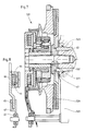
- Fig. 2 einen auf einer mit einer Kurbelwelle verbundenen Zentralschraube angeordneten, erfindungsgemäßen Antrieb mit einem axial zwischen einem Planetengetriebe und einem Riemenrad angeordneten Wälzlager im Längsschnitt;
- Fig. 3 den erfindungsgemäßen Antrieb mit einem radial über dem Wälzlager angeordneten Riemenrad;
- Fig. 4 den erfindungsgemäßen Antrieb mit einem als variables Riemenrad ausgebildeten Außenring des Wälzlagers;
- Fig. 5 den erfindungsgemäßen Antrieb mit in einen Klemmrollenfreilauf integrierten Getriebezahnrädern;
- Fig. 6 den erfindungsgemäßen Antrieb mit einer Schmierstoffversorgung;
- Fig. 7 den erfindungsgemäßen Antrieb mit einer auf der Kurbelwelle angeordneten Austauschnabe;
- Fig. 8 als Einzelheit einen als Drehmomentenstützarm ausgebildeten Deckel eines Magnettopfes eines Bremsmagneten;
- Fig. 9 eine Einbauvariante, bei der der erfindungsgemäße Antrieb unmittelbar am Motorblock angeflanscht ist; und
- Fig. 10 ein an den erfindungsgemäßen Aggregateantrieb angeschlossenes, elektronisches Steuergerät, als Blockschaltbild.
- Fig. 1 is a schematic representation of the controllable drive according to the invention for switching on with height rer speed as a crankshaft of an internal combustion engine rotating belt level;
- 2 shows a longitudinal section of a drive according to the invention arranged on a central screw connected to a crankshaft with a roller bearing arranged axially between a planetary gear and a belt wheel;
- 3 shows the drive according to the invention with a belt wheel arranged radially above the roller bearing;
- 4 shows the drive according to the invention with an outer ring of the roller bearing designed as a variable belt wheel;
- 5 shows the drive according to the invention with gearwheels integrated in a clamping roller freewheel;
- 6 shows the drive according to the invention with a lubricant supply;
- 7 shows the drive according to the invention with an exchange hub arranged on the crankshaft;
- 8 shows in detail a cover of a magnetic pot of a brake magnet designed as a torque support arm;
- 9 shows an installation variant in which the drive according to the invention is flanged directly to the engine block; and
- 10 shows an electronic control unit connected to the unit drive according to the invention, as a block diagram.
Ein regelbarer Aggregateantrieb 1 weist eine mit der Kurbelwelle 2 einer Brennkraftmaschine 3 verbundene Zentralschraube 4 auf. Die Zentralschraube 4 ist mit einer Laufbuchse 5 mit Klemmrollenfreilauf für ein Sonnenrad 6 versehen, das in ein außerdem mit einem Getriebehohlrad 7 eines variablen Riemenrades 8 kämmendes Planetengetriebe 9 eingreift, d.h. das Planetengetriebe 9 ist radial zwischen dem Getriebehohlrad 7 und dem Sonnenrad 6 angeordnet. Dem Sonnenrad 6 ist ein über Elektrokabel 10 an eine nicht dargestellte Stromquelle angeschlossener Bremsmagnet 11 zugeordnet.A
Wenn der Bremsmagnet 11 bestromt wird, steht das Sonnenran 6 still und das Riemenrad 8 wird über das Planetengetriebe 9 mit einer Übersetzung ins Schnelle angetrieben; diese den zugeschalteten Hochtrieb darstellende Betriebssituation, in der das Sonnenrad 6 nicht rotiert, ist in der oberen Hälfte der Fig. 1 dargestellt. Der Pfeil 12 gibt hierbei den Antriebsverlauf wieder, nämlich ausgehend von der Kurbelwelle 2 über einen Planetenträgerflansch 13 in das sich um das feststehende Sonnenrad 6 drehende Planetengetriebe 9 und bis in das Getriebehohlrad 7 bzw. das Riemenrad 8. Ist hingegen der Bremsmagnet 11 stromlos, so blockiert der Klemmrollenfreilauf der Laufbuchse 5; die Buchse 5 nimmt dann das Sonnenrad 6 mit der Drehzahl der Kurbelwelle 2 mit. Das Planetengetriebe 9 wirkt in diesem Fall als Kupplung und treibt entsprechend das Getriebehohlrad 7 bzw. das Riemenrad 8 mit der Kurbelwellendrehzahl an; dieser Antriebsverlauf wird in der unteren Hälfte der Fig. 1 durch den Pfeil 14 wiedergegeben.When the
Die aufgrund der Erfindung erreichte Kompaktbauweise des regelbaren Aggregateantriebs 1 ergibt sich aus der in Fig. 2 dargestellten konkreten Einbausituation. Das variable, beispielsweise aus Blech gerollte, mehrere Riemenscheiben besitzende Riemenrad 8 weist einen axialen Ringkragen 15 auf, der sich in Richtung zur Kurbelwelle 2 erstreckt und an seinem der Kurbelwelle 2 zugewandten Ende als Getriebehohlrad 7 ausgebildet und zu diesem Zweck mit einem Innenzahnkranz 16 versehen ist. Der Innenzahnkranz 16 kämmt mit dem Planetengetriebe 9, das seinerseits in das mit einem Lager 17 auf der Laufbuchse 5 gelagerte Sonnenrad 6 eingreift; der Klemmrollenfreilauf 18 der Laufbuchse 5 ist lediglich schematisch dargestellt und kann beispielsweise als Sperrad mit Klemmrampen und Klemmrollen ausgebildet sein. Axial innen, d.h. an der von der Kurbelwelle 2 abgewandten Seite des Innenzahnkranzes 16 ist ein Wälzlager 19 angeordnet, das dort in den Ringkragen 15 des Riemenrades 8 eingesetzt ist und aufgrund seiner Einbaulage und seines Durchmessers eine Stützbreite 20 zur Verfügung stellt, die die gesamte axiale Länge des von dem Lager getragenen Riemenrades 8 mit Ringkragen 15 erfaßt. Ein zweites Lager, das axial zusätzlichen Bauraum erfordern würde, kann somit entfallen.The compact design of the
Der Bremsmagnet 11 ist an einem Stützarm 21 befestigt, der gleichzeitig die Führung der den Magneten 11 mit Strom versorgenden Elektrokabel 10 übernimmt. Der Stützarm 21 ist mit einer Öse 22 auf einen im Motorblock 23 der Brennkraftmaschine befestigten Bolzen 24 gesteckt und somit daran gehindert, aufgrund der auftretenden Drehmomente zu rotieren. Der Bremsmagnet 11 wird von einem auf der Laufbuchse 5 angeordneten Rillenkugellager 25 getragen, wobei ein Abschnitt des Außenmantels der Laufbuchse 5 als Innenring 26 für die Kugeln des Kugellagers 25 ausgebildet ist. Das - von der Zentralschraube 4 ausgehend - radial innenliegende Rillenkugellager 25 und die demgegenüber radial außenliegende Öse 22 sind zwar mit Abstand voneinander, jedoch in einer Flucht liegend angeordnet, d.h. die Öse 22 liegt genau unter der Laufbahn bzw. dem Innenring 26 des einreihigen Rillenkugellagers 25. Auf diese Weise ergibt sich bei einem an den Stützarm 21 angreifenden Drehmoment eine durch die Öse 22 und das Rillenkugellager 25 verlaufende Kraftangriffsebene 27; es können somit keine verkantenden Kräfte auf das Rillenkugellager 25 einwirken, so daß auf ein zweites Kugellager verzichtet werden kann.The
Ein mit der Drehzahl der Kurbelwelle 2 rotierender Schwingungsdämpfer 28 ist am Planetenträgerflansch 13 befestigt und überkragt den Ringkragen 15 in Richtung auf das variable Riemenrad 8 mit einem zweiten, wie der Schwingungsdämpfer 28 mit der Drehzahl der Kurbelwelle 2 umlaufenden Riemenrad 29. Das variable, erste Riemenrad 8 und das zweite Riemenrad 29 liegen axial auf engstem Raum nebeneinander. Zum Zuschalten des Hochtriebes, d.h. des mit einer höheren Drehzahl als die Kurbelwelle 2 umlaufenden variablen Riemenrades 8 übt der geschaltete mit Strom versorgte Bremsmagnet 11 eine Bremskraft auf eine Bremsscheibe 30 aus, die das Sonnenrad 6 festlegt.A
Bei dem regelbaren Aggregateantrieb 101 gemäß Fig. 3 befindet sich lediglich noch das Planetengetriebe 109, das aus dem vom axialen Ringkragen 115 des variablen Riemenrades 108 gebildeten Getriebehohlrad 107, den Planetenrädern 109a und dem Sonnenrad 106 besteht, seitlich neben dem die gesamte axiale Länge des Aggregateantriebes 101 abstützenden Wälzlager 119. Hingegen ist das variable Riemenrad 108, verglichen mit dem in Fig. 2 dargestellten Aggregateantrieb, axial in Richtung des Motorblockes 123 verlagert und radial über dem Wälzlager 119 angeordnet, womit sich ein zentraler Riemenzug und eine geringere axiale Breite des Aggregateantriebes 101 ergeben. Ein solcher zentraler Riemenzug liegt auch bei dem in Fig. 4 dargestellten Aggregateantrieb 201 vor, bei dem der Außenring 219a des Wälzlagers 219 sowohl das die Planetenräder 209a des Planetengetriebes 209 übergreifende Getriebehohlrad 207 als auch gleichzeitig einen Träger für das variable Riemenrad 208 bildet; ein Schwingungsdämpfer entfällt bei diesem Antrieb. Die sich aufgrund des zentralen Riemenzuges ergebende Lasteinleitung erlaubt es, das variable Riemenrad 208 völlig aus Kunststoff herzustellen.In the controllable
Eine sowohl herstellungstechnisch günstige als auch für den Betrieb des Aggregateantriebes 301 vorteilhafte Werkstoffpaarung liegt vor, wenn - wie in Fig. 5 dargestellt - der Innenzahnkranz 316, d.h. die Zähne des Getriebehohlrades 307 und die Zähne 306a des Sonnenrades 306 aus Kunststoff bestehen, während die Planetenräder 309a des Planetengetriebes 309 aus Stahl hergestellt sind. Bei der in der oberen Hälfte von Fig. 5 dargestellten Ausführung bildet der Außenring 319a des Wälzlagers 319 das Getriebehohlrad 307, so daß für den mit Kunststoff umspritzten Innenzahnkranz 316 als Trägermaterial Stahl zur Verfügung steht. Das Sonnenrad 306 und dessen mit Kunststoff beschichteten Zähne 306a sind ein integrierter Bestandteil des Klemmrollenfreilaufs 318 der Laufbuchse 305.A material pairing that is both technically favorable and advantageous for the operation of the
Ein völlig aus Kunststoff bestehendes Getriebehohlrad 307a ist in der unteren Hälfte von Fig. 5 dargestellt. Das Vollkunststoff-Getriebehohlrad 307a ist dabei entweder mit dem Ringkragen 315 des variablen Riemenrades 308 oder mit dem Außenring 319a des Wälzlagers 319 fest verankert, vorzugsweise einstückig verbunden, je nachdem ob der Ringkragen 315 oder der Außenring 319a des Wälzlagers 319 als Hülse für das Getriebehohlrad 307a ausgebildet ist; in Fig. 5 sind beide Alternativen dargestellt. Der Ringkragen 315 bzw. der Außenring 319a ist mit Durchbrüchen 54 versehen; die Außenfläche des Ringkragens 315 bzw. des Außenrings 319a weist Nuten 55 auf, so daß der eingespritzte Kunststoff die Durchbrüche 54 durchdringen, sich in den Nuten 55 verteilen und eine innige Verbindung mit dem Trägermaterial (Hülse) eingehen kann.A
Zur Versorgung des regelbaren Aggregateantriebes 401 mit Fett oder Öl ist gemäß Fig. 6 im Schwingungsdämpfer 428 ein Ringraum 56 angeordnet, der gegebenenfalls mehrere Speicher aufweisen kann. In den nach außen hin mittels einer Dichtung 57 abgedichteten Ringraum 56 eingelagertes Schmierfett gelangt während des Stillstands des Aggregateantriebs 401 über eine oder mehrere Verbindungsnuten 58 zu den Zahnrädern des Planetengetriebes 409; während des Betriebes wird das Fett hingegen fliehkraftbedingt über die Verbindungsnuten 58 wieder in den Ringraum 56 gedrückt. Alternativ kann Schmieröl in das Innere des Planetengetriebes 409 geleitet und während des Betriebes im Ringraum 56 bevorratet werden; das Öl wird über einen vom Motorblock 423 her durch die den Aggregateantrieb 401 tragende Zentralschraube 404 verlaufenden Ölzuströmkanal 59 zugeführt. Überflüssiges Öl wird über einen Ölabströmkanal 60 zurückgeführt. Mittels einer im Ölzuströmkanal 59 angeordneten Düse 61 wird das Schmieröl dosiert und lediglich einmal pro Umlauf zugeführt.To supply the
In Fig. 7 ist eine Aggregateeinheit 501 dargestellt, deren axiale Baugröße sich mittels einer Austauschnabe 62 beliebig variieren läßt. Es lagert nicht mehr der Planetenträgerflansch 513 mit einer Nabe, sondern die außerdem mit dem Schwingungsdämpfer 528 verschweißte Austauschnabe 62 auf der Kurbelwelle 502 und ist somit axial zwischen dem Planetenträgerflansch 513 und dem Motorblock 523 angeordnet. Der Planetenträgerflansch 513 liegt der Austauschnabe 62 flächig und als Druckstück an, so daß sich ein Klemmverbund ergibt, bei dem das Drehmoment über Reibschluß von der Kurbelwelle 502 auf den Aggregateantrieb 501 übertragen wird. Je nach Wahl der Austauschnabe 62 läßt sich der in seinen Abmessungen festliegende Aggregateantrieb 501 an unterschiedliche Einbaubedingungen variabel anpassen; es braucht lediglich eine entsprechend dickere oder dünnere Austauschnabe 62 eingebaut zu werden.7 shows an
Ein von räumlichen Bedingungen und Motorabmessungen unabhängiger Einbau des regelbaren Aggregateantriebes wird auch durch einen in Fig. 8 dargestellten, variablen Drehmomentenstützarm verbessert, der sich aus einem den Magnettopf 64 des Bremsmagneten 11 verschließenden, mit einer Lasche 65 versehenen Stahldeckel 66 und einem der Lasche 65 zugeordneten Gegenstecker 67 zusammensetzt. Je nach Motorabmessung braucht entweder lediglich ein Deckel mit einer entsprechend längeren oder kürzeren Lasche 65 oder der mittels der Öse 22 am Motorblock befestigte Gegenstecker 67 gegen einen längeren oder kürzeren Gegenstecker ausgetauscht zu werden. Da es sich bei diesem variabel anpassbaren Drehmomentenstützarm um eine Steckverbindung handelt, ist das Montieren und Demontieren sehr einfach.An installation of the controllable aggregate drive that is independent of spatial conditions and engine dimensions is also improved by a variable torque support arm shown in FIG. 8, which consists of a
Bei der in Fig. 9 dargestellten Kompakt-Bauweise eines regelbaren Aggregateantriebes 601 erfolgt der Antrieb nicht über die Kurbelwelle der Brennkraftmaschine, sondern über ein angetriebenes Riemenrad 68, das dem variablen, seitlich neben dem Wälzlager 619 angeordneten Riemenrad 608 benachbart ist. Das Wälzlager 619 ist - wie bei der Ausführung gemäß Fig. 2 - axial zwischen dem variablen Riemenrad 608 und dem Planetengetriebe 609 angeordnet. Der Aggregateantrieb 601 wird von einer Achse 69 eines mittels Schrauben 70 am Motorblock 623 befestigten Flansches 71 getragen. Die mit Nadellagern 72 versehene Tragachse 69 ragt in die Bohrung der zentralen Laufbuchse 605 hinein. Die Kompakt-Bauweise des Aggregateantriebes 601 wird durch das Anflanschen am Motorblock 623 oder an einer nicht dargestellten, am Motorblock befestigten Halterung erreicht. Ansonsten werden auch bei diesem Aggregateantrieb die gleichen Bauteile wie bei den vorbeschriebenen Antrieben verwendet, so daß sich bei allen beschriebenen Aggregateantrieben ein höchst anpassungsfähiges Baukastensystem verwirklichen läßt.In the compact design of a
Anhand des Blockschaltbildes gemäß Fig. 10 wird beispielhaft für den Aggregateantrieb 1 gemäß Fig. 2 eine - für die übrigen beschriebenen Aggregateantriebe gleichermaßen anzuwendende - Steuerung mittels eines elektronischen Steuergerätes 31 dargestellt. Ein verschiedenste Verbraucher 32 versorgendes Bordnetz 33 ist sowohl an einen Drehstromgenerator 34 als auch einen Akkumulator 35 angeschlossen. Der Generator 34 läßt sich ebenso wie eine Hydraulikpumpe 36, ein Klimakompressor 37 und eine Kühlwasserpumpe 38 mit Motorlüfter 39 über das Riemenrad 8 mit höherer Drehzahl antreiben, d.h. dem Aggregateantrieb 1 zuschalten. Der nicht ständig benötigte Klimakompressor 37 wird dem Aggregateantrieb 1 mittels einer Magnetkupplung 40 zugeschaltet.Based on the block diagram according to FIG. 10, a control by means of an
Das elektronische Steuergerät 31 besitzt als integrierte Bestandteile eine Bedarfssteuerung 41, eine Klimaanlagensteuerung 42 und eine Hochtriebssteuerung 43. Die Bedarfssteuerung 41 ist über eine Steuerleitung 44 mit einem am Akkumulator 35 angeordneten Stromsensor 45, die Hochtriebssteuerung 43 über Steuerleitungen 46 bzw. 47 an einen Temperatursensor 48 des Bremsmagneten bzw. einen Drehzahlgeber 49 des Aggregateantriebes 1 und die Klimaanlagensteuerung 42 über eine Steuerleitung 50 an die Magnetkupplung 40 des Klimakompressors 37 angeschlossen. Sowohl die Bedarfssteuerung 41 als auch die Klimaanlagensteuerung 42, in der mehrere, durch Pfeile 51 symbolisierte Drehzahleingänge nicht näher bezifferter Verbraucher ausgewertet werden, bei denen es sich beispielsweise um die Hydraulikpumpe 36 und die Kühlwasserpumpe 38 mit Motorlüfter 39 handeln kann, sind mit Steuerleitungen 52, 53 an die Hochtriebssteuerung 43 angeschlossen. Aufgrund der miteinander verknüpften Steuerungen 41, 42, 43 bieten sich mittels des elektronischen Steuergerätes 31 flexible Eingriffsmöglichkeiten zur Bestimmung der das Zuschalten des Hochtriebs über das variable Riemenrad 8 auslösenden Schaltdrehzahl.The
Mittels des Stromsensors 45 läßt sich beispielsweise der Leistungsaustausch des Akkumulators 35 mit dem Bordnetz 33 bzw. dem Generator 34 erfassen. Sobald ein festgelegter Grenzwert überschritten wird, wenn beispielsweise der vom Generator 34 erzeugte Strom nicht dem momentanen Bedarf des Bordnetzes 33 entspricht, oder der Akkumulator 35 leer ist und Strom vom Generator 34 aufnimmt, wird der Hochtrieb des variablen Riemenrades 8 zugeschaltet. Durch die über die Eingänge 51 in die Klimaanlagensteuerung 42 eingegebenen Drehzahlen wird dem Aggregat, gemäß dem Beispiel dem Klima kompressor 37, das die höchste Drehzahl erfordert, eine Priorität eingeräumt und der Hochtrieb des variablen Riemenrades 7 auf jeden Fall dann zugeschaltet, wenn dieses Aggregat, der Klimakompressor 37, mit der Nennleistung versorgt werden muß. Jedoch wird oberhalb einer bestimmten, durch den Drehzahlgeber 49 ermittelten Motordrehzahl der Hochtrieb stets ausgeschaltet und das Antriebsaggregat 1 auf direkten Durchtrieb über die Kurbelwelle 2 umgeschaltet, da alle zu versorgenden Aggregate bei dieser Grenz-Motordrehzahl über ein ausreichendes Leistungsvermögen verfügen.By means of the
Der im oder am Bremsmagneten 11 angeordnete Temperatursensor 48 bewirkt bei einer übermäßigen Wärmeentwicklung, die sich bei Störungen aufgrund höherer Temperaturen einstellt, eine Sicherheitsabschaltung. Dabei wird der Bremsmagnet 11 abgeschaltet, d.h. stromlos gesetzt, und die Aggregate werden im direkten Durchtrieb über die Kurbelwelle 2 angetrieben.The
Es wird somit aufgrund insbesondere der in das variable Riemenrad bzw. dessen axialen Ringkragen integrierten Getriebehohlrad- und Riemenradlagerung ein Aggregate-Antrieb in Kompakt-Bauweise ermöglicht, der sich in den Motorraum ohne Änderung der räumlichen Anordnung des Motors oder seiner Aggregate einbauen läßt. Der erreichte Raumgewinn erlaubt es, zusätzlich den Schwingungsdämpfer in die Antriebseinheit einzubeziehen und neben dem Hochtrieb über das variable Riemenrad noch einen ständig mit der Kurbelwellendrehzahl umlaufenden Antrieb bereitzustellen. Außerdem gestattet das Ansteuerungsverfahren mittels des elektronischen Steuergerätes flexible Eingriffe, insbesondere zum drehzahlabhängigen Zuschalten des Hochtriebs, d.h. zum Festlegen der Schaltdrehzahl.It is thus possible due to in particular in the variable pulley or its axial ring collar integrated gear ring and pulley bearing an aggregate drive in a compact design, which can be installed in the engine compartment without changing the spatial arrangement of the engine or its aggregates. The gain in space allows the vibration damper to be included in the drive unit and, in addition to the high drive via the variable pulley, to provide a drive that continuously rotates at the crankshaft speed. In addition, the control method by means of the electronic control unit allows flexible interventions, in particular for the speed-dependent activation of the high drive, i.e. for setting the switching speed.
Claims (36)
Applications Claiming Priority (2)
| Application Number | Priority Date | Filing Date | Title |
|---|---|---|---|
| DE19883819986 DE3819986A1 (en) | 1988-06-11 | 1988-06-11 | ADJUSTABLE DRIVE AND METHOD FOR ITS CONTROL |
| DE3819986 | 1988-06-11 |
Publications (1)
| Publication Number | Publication Date |
|---|---|
| EP0346743A2 true EP0346743A2 (en) | 1989-12-20 |
Family
ID=6356387
Family Applications (1)
| Application Number | Title | Priority Date | Filing Date |
|---|---|---|---|
| EP19890110255 Withdrawn EP0346743A2 (en) | 1988-06-11 | 1989-06-07 | Adjustable driving apparatus and method of controlling it |
Country Status (2)
| Country | Link |
|---|---|
| EP (1) | EP0346743A2 (en) |
| DE (1) | DE3819986A1 (en) |
Cited By (10)
| Publication number | Priority date | Publication date | Assignee | Title |
|---|---|---|---|---|
| EP0599125A1 (en) * | 1992-11-12 | 1994-06-01 | Ford-Werke Aktiengesellschaft | Driving arrangement for the balancing shaft of a V-type engine |
| EP0654620A1 (en) * | 1993-11-18 | 1995-05-24 | Firma Carl Freudenberg | Auxiliary drive |
| DE19728723A1 (en) * | 1997-07-04 | 1999-01-07 | Bayerische Motoren Werke Ag | Drive unit for motor vehicles |
| WO2001047739A1 (en) * | 1999-12-27 | 2001-07-05 | Speed Selector, Inc. | Variable speed drive system |
| WO2005071819A1 (en) * | 2004-01-13 | 2005-08-04 | The Gates Corporation | Two speed transmission and belt drive system |
| DE102006060872A1 (en) * | 2006-12-22 | 2008-06-26 | Dr.Ing.H.C. F. Porsche Ag | Locking nozzle for discharge of reactive plastic in a vacuum |
| US7758465B2 (en) | 2007-06-04 | 2010-07-20 | The Gates Corporation | Damped planetary transmission |
| WO2012000487A1 (en) * | 2010-06-29 | 2012-01-05 | Schaeffler Technologies Gmbh & Co. Kg | Crankshaft pulley |
| WO2012130196A1 (en) * | 2011-03-28 | 2012-10-04 | Schaeffler Technologies AG & Co. KG | Crankshaft belt pulley |
| WO2012000474A3 (en) * | 2010-06-29 | 2013-03-28 | Schaeffler Technologies AG & Co. KG | Crankshaft pulley |
Families Citing this family (6)
| Publication number | Priority date | Publication date | Assignee | Title |
|---|---|---|---|---|
| US5330393A (en) * | 1991-06-07 | 1994-07-19 | Fichtel & Sachs Ag | Gear unit for combination with an auxiliary power consuming unit of a motor-vehicle |
| US5358456A (en) * | 1991-06-07 | 1994-10-25 | Fichtel & Sachs Ag | Gear unit for combination with an auxiliary power consuming unit of a motor-vehicle |
| DE19623525A1 (en) * | 1996-06-13 | 1997-12-18 | Schaeffler Waelzlager Kg | Crankshaft mounted belt drive to ancillary plant |
| DE10161700A1 (en) * | 2001-12-15 | 2003-06-18 | Bayerische Motoren Werke Ag | Variable overhead belt drive has switching module consisting of magnetic coupling and overtaking freewheel between its drive input and drive output |
| DE102008033177A1 (en) * | 2008-07-15 | 2010-01-21 | Volkswagen Ag | Adjustable compressor, particularly for use in refrigerant circuit of air conditioning vehicle, has belt pulley rotatably mounted on drive shaft for drive belt, where gear is arranged in belt pulley |
| DE102012105301A1 (en) * | 2012-06-19 | 2013-12-19 | C & S Sonderfahrzeuge GmbH | An accessory for controlling one or more hydraulic drives |
-
1988
- 1988-06-11 DE DE19883819986 patent/DE3819986A1/en not_active Withdrawn
-
1989
- 1989-06-07 EP EP19890110255 patent/EP0346743A2/en not_active Withdrawn
Cited By (16)
| Publication number | Priority date | Publication date | Assignee | Title |
|---|---|---|---|---|
| EP0599125A1 (en) * | 1992-11-12 | 1994-06-01 | Ford-Werke Aktiengesellschaft | Driving arrangement for the balancing shaft of a V-type engine |
| EP0654620A1 (en) * | 1993-11-18 | 1995-05-24 | Firma Carl Freudenberg | Auxiliary drive |
| DE19728723A1 (en) * | 1997-07-04 | 1999-01-07 | Bayerische Motoren Werke Ag | Drive unit for motor vehicles |
| WO2001047739A1 (en) * | 1999-12-27 | 2001-07-05 | Speed Selector, Inc. | Variable speed drive system |
| CN100471714C (en) * | 2004-01-13 | 2009-03-25 | 盖茨公司 | Two speed transmission and belt drive system |
| JP2007518037A (en) * | 2004-01-13 | 2007-07-05 | ザ ゲイツ コーポレイション | Two-speed transmission and belt drive system |
| KR100805178B1 (en) | 2004-01-13 | 2008-02-21 | 더 게이츠 코포레이션 | Two speed transmission and belt drive system |
| WO2005071819A1 (en) * | 2004-01-13 | 2005-08-04 | The Gates Corporation | Two speed transmission and belt drive system |
| AU2004314557B2 (en) * | 2004-01-13 | 2009-09-10 | The Gates Corporation | Two speed transmission and belt drive system |
| US7727115B2 (en) | 2004-01-13 | 2010-06-01 | The Gates Corporation | Two speed transmission and belt drive system |
| DE102006060872A1 (en) * | 2006-12-22 | 2008-06-26 | Dr.Ing.H.C. F. Porsche Ag | Locking nozzle for discharge of reactive plastic in a vacuum |
| US7882910B2 (en) | 2006-12-22 | 2011-02-08 | Dr. Ing. H.C.F. Porsche Aktiengesellschaft | Hybrid drive for a motor vehicle |
| US7758465B2 (en) | 2007-06-04 | 2010-07-20 | The Gates Corporation | Damped planetary transmission |
| WO2012000487A1 (en) * | 2010-06-29 | 2012-01-05 | Schaeffler Technologies Gmbh & Co. Kg | Crankshaft pulley |
| WO2012000474A3 (en) * | 2010-06-29 | 2013-03-28 | Schaeffler Technologies AG & Co. KG | Crankshaft pulley |
| WO2012130196A1 (en) * | 2011-03-28 | 2012-10-04 | Schaeffler Technologies AG & Co. KG | Crankshaft belt pulley |
Also Published As
| Publication number | Publication date |
|---|---|
| DE3819986A1 (en) | 1989-12-14 |
Similar Documents
| Publication | Publication Date | Title |
|---|---|---|
| EP0346743A2 (en) | Adjustable driving apparatus and method of controlling it | |
| DE60127364T2 (en) | driving device | |
| DE60014291T2 (en) | Motor / generator unit for a motor vehicle | |
| DE10160466C1 (en) | Motor vehicle drive device, has two idlers with idler parts connected to drive shaft, coaxial hollow intermediate shaft through which drive shaft passes and rotor of electric motor | |
| DE112010005824B4 (en) | Control device for a vehicle | |
| DE102004050137B4 (en) | Oil supply device | |
| DE4118729A1 (en) | DEVICE FOR LUBRICATING A VEHICLE ENGINE | |
| DE102008045202B4 (en) | Coaxial starter for an internal combustion engine | |
| DE60314703T2 (en) | Motor vehicle drive system | |
| DE102010047507A1 (en) | Oil cooled engine / generator for a motor vehicle powertrain | |
| DE2251220A1 (en) | CHANGEABLE SPEED ELECTRIC DRIVE | |
| DE112011100712T5 (en) | DRIVE DEVICE FOR A VEHICLE | |
| DE2349945A1 (en) | DRIVE FOR THE COOLING FAN OF A MOTOR VEHICLE ENGINE | |
| DE10049197A1 (en) | Hybrid vehicle with IC engine and electric motor has stator of electric motor supported by transmission housing | |
| DE102011088060A1 (en) | Pump unit with a pump and a hybrid drive | |
| WO2016087101A1 (en) | Electric drive unit, hybrid drive device, and vehicle | |
| DE102009033633A1 (en) | Generator drive system for an internal combustion engine | |
| EP1556634A1 (en) | Motor vehicle drive device | |
| DE102006030041A1 (en) | Oil pump for e.g. automatic transmission of e.g. hybrid vehicle, has electrical machine connected with pump parts via mechanical effective connector, where connector is arranged in area between output shaft and pump parts | |
| WO2009067981A1 (en) | Method for controlling the operation of a generator in a vehicle drive train and vehicle drive train | |
| DE102010051041A1 (en) | Drive assembly for motor car, has transmission unit comprising two gear wheels meshed with one another and forming gear pump, and aggregate unit for supplying refreshing and/or lubricating fluid through channel | |
| WO2010049244A1 (en) | Hybrid drive unit | |
| DE112009000477T5 (en) | Stepless belt drive system | |
| DE102006003213A1 (en) | Lubricating oil supplying device, has hollow shaft, within which ladling device is arranged, which protrudes into oil ring rotating in operation of rotary hollow shaft | |
| DE10346921B4 (en) | By means of an internal combustion engine of a motor vehicle driven belt drive |
Legal Events
| Date | Code | Title | Description |
|---|---|---|---|
| PUAI | Public reference made under article 153(3) epc to a published international application that has entered the european phase |
Free format text: ORIGINAL CODE: 0009012 |
|
| AK | Designated contracting states |
Kind code of ref document: A2 Designated state(s): DE FR GB IT SE |
|
| STAA | Information on the status of an ep patent application or granted ep patent |
Free format text: STATUS: THE APPLICATION HAS BEEN WITHDRAWN |
|
| RAP3 | Party data changed (applicant data changed or rights of an application transferred) |
Owner name: PIERBURG GMBH |
|
| 18W | Application withdrawn |
Withdrawal date: 19900112 |
|
| R18W | Application withdrawn (corrected) |
Effective date: 19900112 |