EP0345403A1 - Plastic cap comprising a cover articulated by a spring-type hinge - Google Patents
Plastic cap comprising a cover articulated by a spring-type hinge Download PDFInfo
- Publication number
- EP0345403A1 EP0345403A1 EP88420183A EP88420183A EP0345403A1 EP 0345403 A1 EP0345403 A1 EP 0345403A1 EP 88420183 A EP88420183 A EP 88420183A EP 88420183 A EP88420183 A EP 88420183A EP 0345403 A1 EP0345403 A1 EP 0345403A1
- Authority
- EP
- European Patent Office
- Prior art keywords
- cap
- pouring part
- zone
- rigid tab
- hinge
- Prior art date
- Legal status (The legal status is an assumption and is not a legal conclusion. Google has not performed a legal analysis and makes no representation as to the accuracy of the status listed.)
- Withdrawn
Links
Images


Classifications
-
- B—PERFORMING OPERATIONS; TRANSPORTING
- B65—CONVEYING; PACKING; STORING; HANDLING THIN OR FILAMENTARY MATERIAL
- B65D—CONTAINERS FOR STORAGE OR TRANSPORT OF ARTICLES OR MATERIALS, e.g. BAGS, BARRELS, BOTTLES, BOXES, CANS, CARTONS, CRATES, DRUMS, JARS, TANKS, HOPPERS, FORWARDING CONTAINERS; ACCESSORIES, CLOSURES, OR FITTINGS THEREFOR; PACKAGING ELEMENTS; PACKAGES
- B65D47/00—Closures with filling and discharging, or with discharging, devices
- B65D47/04—Closures with discharging devices other than pumps
- B65D47/06—Closures with discharging devices other than pumps with pouring spouts or tubes; with discharge nozzles or passages
- B65D47/08—Closures with discharging devices other than pumps with pouring spouts or tubes; with discharge nozzles or passages having articulated or hinged closures
- B65D47/0804—Closures with discharging devices other than pumps with pouring spouts or tubes; with discharge nozzles or passages having articulated or hinged closures integrally formed with the base element provided with the spout or discharge passage
- B65D47/0809—Closures with discharging devices other than pumps with pouring spouts or tubes; with discharge nozzles or passages having articulated or hinged closures integrally formed with the base element provided with the spout or discharge passage and elastically biased towards both the open and the closed positions
- B65D47/0814—Closures with discharging devices other than pumps with pouring spouts or tubes; with discharge nozzles or passages having articulated or hinged closures integrally formed with the base element provided with the spout or discharge passage and elastically biased towards both the open and the closed positions by at least three hinge sections, at least one having a length different from the others
Definitions
- the subject of the present invention is a plastic plug comprising a cap articulated by a spring-effect hinge.
- This cap is more precisely of the type comprising a pouring part intended to be mounted definitively on the neck of the container to be equipped, and a cap intended to close the pouring part and mounted articulated on the latter by a spring-effect hinge, the different parts of the stopper, namely the pouring part, the cap and the hinge coming from one-piece molding.
- Such a stopper is advantageous in that the cap remains integral with the pouring part, it cannot be lost during the period of opening of the container.
- the hinge having a spring effect
- the cover can occupy, when no stress is exerted on it, that two stable positions corresponding, respectively, to a fully open position and a closed position.
- the cap cannot therefore remain in a stable intermediate position in which it would impede the flow of the fluid contained in the container thus equipped.
- the hinge disposed laterally with respect to the respective bodies of the pouring part and of the cap, comprises a thinned zone forming a film hinge at the level of which the geometric axis of pivoting of the cap is located relative to the pouring part.
- This hinge also comprises at least one spring element generally constituted by a tab which, delimited by two slots parallel to the axis of the stopper, is formed partly in the pouring part, and partly in the cap, the ends of the slots being themselves connected by zones of reduced thickness forming a film hinge, allowing the tab to tilt, respectively, relative to the pouring part and relative to the cap.
- the present invention aims to remedy these drawbacks by providing a plug with integrated hinge which does not require the provision of cutouts in the cap.
- the stopper which it concerns, of the type comprising a pouring part intended to be mounted on the neck of the container to be fitted and a cap intended to close the pouring part and mounted articulated on the latter by a spring-effect hinge comprising two tabs arranged laterally with respect to the stopper, connecting the pouring part and the cap, each having a thinned part forming a film hinge providing a geometric axis of pivoting of the cap relative to the pouring part, between which is a part having a spring effect, is characterized in that the part having a spring effect is formed in combination: - by a rigid tab made in the pouring part and delimited by two slots parallel to the axis of the stopper as well as by two thinned zones forming a film hinge, oriented perpendicular to the slots and one of which is disposed in the junction zone between the pouring part and the cap, and - By an elastically deformable zone provided in the cap in the extension of the rigid tab.
- the rigid tab, and consequently the cap will tend to tilt automatically either in an opening direction or in a closing direction. of the plug on either side of this line, under the effect of relaxation of the material, which provides the desired spring effect.
- the elastically deformable zone, formed in the cap in the extension of the rigid tab consists of a zone of material of the same thickness as the rest of the cap, and delimited by two lines obtained by thinning of material extending substantially in the extension of the slots delimiting the rigid tab, on the height of the skirt of the cap and on a part of the bottom thereof.
- the elastically deformable zone formed in the cap and in the extension of the rigid tab is constituted by an area of material of less thickness than the rest of the cap and extending over the height of the skirt of the cap and part of the bottom thereof.
- the cap according to the invention has the advantage of being much more pleasant in appearance than traditional caps, since the cap has absolutely no cutout.
- this structure results in a simplification of the production of the stopper, the mold used being less complex since it does not require the production of a tab cut out inside the cover.
- the stopper shown in the drawing and designated by the general reference 2 , comprises a pouring part 3 intended to be permanently mounted on the neck of the container to be fitted.
- This pouring part comprises a first skirt 4 intended for fixing the stopper to the neck of the container, not shown, and is itself surrounded by a second skirt 5 .
- the first skirt 4 is closed by a bottom 6 in the central part of which an opening 7 is formed.
- This cap also includes a cap 8 mounted articulated on the pouring part 3 , comprising a cylindrical skirt 9 closed at one of its ends by a bottom 10 of the central part from which protrudes a finger 11 intended to come to engage with sealing in the orifice 7 , in the closed position of the plug.
- the cap 8 is connected to the pouring part 3 by means of two legs 12 projecting laterally from the cap, and comprising a thinned central part 13 forming a film hinge, the two hinges 13 of the two legs 12 delimiting the geometric axis O pivoting of the cap relative to the pouring part.
- a part having a spring effect constituted by a rigid tab 14 formed in the pouring part 3 and delimited by two slots parallel to the axis of the stopper as well as by two thinned zones 15 and 16 each forming a film hinge oriented perpendicular to the slots.
- the thinned zone 16 is arranged in the junction zone between the pouring part 3 and the cap 8 .
- the rigid tab 14 is extended at the level of the cap 8 by an elastically deformable zone.
- this zone 17 which is elastically deformable, consists of a zone of material of the same thickness as the rest of the cap delimited by two lines 18 of lesser thickness of material extending in line with the slits delimiting the rigid tab, on the height of the skirt 9 and part of the bottom 10 of the cap 8 .
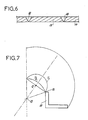
- the hinge 16 should describe a line T1 .
- the hinge line 16 describes an arc of a circle T2 centered on the axis 15 corresponding to the articulation line of the lug 14 on the pouring part 3 .
- this zone 17 which extends the rigid tab, this zone 17 which normally forms, seen in section, a right angle, being capable of flattening to compensate for the difference between the paths T1 and T2 .
- the maximum distance between the trajectories T1 and T2 being located on the line 15-O which is called “neutral line", the tab 14 cannot occupy a stable position corresponding to this line, and will automatically switch to one side or the other of this line, according to the action exerted at the origin by the user under the effect of relaxation of the deformable part 17 which will tend to take again the form in which it was molded.
- this stopper having an integrated spring-effect hinge, has many advantages compared to the existing stoppers on the market, both because of its aesthetics since the cap does not have cutouts, than because of its simplicity of realization, still due to the absence of cutouts of the cap.
- the deformable zone of the cap could be obtained not by providing two lines of smaller thickness of material, but by reducing the thickness of material over the entire surface, or even that the very shape of the pouring part, and the position and the size of its orifice could be different without departing from the scope of the invention.
Abstract
Description
La présente invention a pour objet un bouchon en matière synthétique comportant une coiffe articulée par une charnière à effet de ressort.The subject of the present invention is a plastic plug comprising a cap articulated by a spring-effect hinge.
Ce bouchon est plus précisément du type comprenant une partie verseuse destinée à être montée de façon définitive sur le col du récipient à équiper, et une coiffe destinée à obturer la partie verseuse et montée articulée sur cette dernière par une charnière à effet de ressort, les différentes parties du bouchon, à savoir la partie verseuse, la coiffe et la charnière venant de moulage en une seule pièce.This cap is more precisely of the type comprising a pouring part intended to be mounted definitively on the neck of the container to be equipped, and a cap intended to close the pouring part and mounted articulated on the latter by a spring-effect hinge, the different parts of the stopper, namely the pouring part, the cap and the hinge coming from one-piece molding.
Un tel bouchon est intéressant du fait que la coiffe demeurant solidaire de la partie verseuse, elle ne peut pas être perdue en période d'ouverture du récipient.Such a stopper is advantageous in that the cap remains integral with the pouring part, it cannot be lost during the period of opening of the container.
Un autre avantage réside dans le fait que la charnière possèdant un effet de ressort, la coiffe ne peut occuper, quand aucune contrainte n'est exercée sur elle, que deux positions stables correspondant, respectivement, à une position d'ouverture totale et à une position de fermeture. La coiffe ne peut donc rester dans une position stable intermédiaire dans laquelle elle gênerait l'écoulement du fluide contenu dans le récipient ainsi équipé.Another advantage lies in the fact that the hinge having a spring effect, the cover can occupy, when no stress is exerted on it, that two stable positions corresponding, respectively, to a fully open position and a closed position. The cap cannot therefore remain in a stable intermediate position in which it would impede the flow of the fluid contained in the container thus equipped.
De façon connue, la charnière, disposée latéralement par rapport aux corps respectifs de la partie verseuse et de la coiffe, comprend une zone amincie formant une charnière-film au niveau de laquelle se situe l'axe géométrique de pivotement de la coiffe par rapport à la partie verseuse.In known manner, the hinge, disposed laterally with respect to the respective bodies of the pouring part and of the cap, comprises a thinned zone forming a film hinge at the level of which the geometric axis of pivoting of the cap is located relative to the pouring part.
Cette charnière comprend également au moins un élément formant ressort constitué généralement par une patte qui, délimitée par deux fentes parallèles à l'axe du bouchon, est ménagée pour partie dans la partie verseuse, et pour partie dans la coiffe, les extrémités des fentes étant elles-mêmes reliées par des zones de moindre épaisseur formant charnière-film, permettant le basculement de la patte, respectivement, par rapport à la partie verseuse et par rapport à la coiffe.This hinge also comprises at least one spring element generally constituted by a tab which, delimited by two slots parallel to the axis of the stopper, is formed partly in the pouring part, and partly in the cap, the ends of the slots being themselves connected by zones of reduced thickness forming a film hinge, allowing the tab to tilt, respectively, relative to the pouring part and relative to the cap.
Il en résulte, d'une part, le ménagement de découpes dans la partie verseuse et dans la coiffe qui nuisent à l'esthétique du bouchon et, éventuellement à l'étanchéité du bouchage et, d'autre part, la mise en oeuvre d'un moule de forme complexe pour obtenir la patte ayant un effet de ressort, notamment en raison du fait que le bouchon doit être moulé en position ouverte.This results, on the one hand, in the provision of cutouts in the pouring part and in the cap which adversely affect the aesthetics of the stopper and, possibly, the sealing of the closure and, on the other hand, the implementation of '' a mold of complex shape to obtain the paw having an effect spring, in particular due to the fact that the plug must be molded in the open position.
La présente invention vise à remédier à ces inconvénients en fournissant un bouchon à charnière intégrée ne nécessitant pas le ménagement de découpes dans la coiffe.The present invention aims to remedy these drawbacks by providing a plug with integrated hinge which does not require the provision of cutouts in the cap.
A cet effet, le bouchon qu'elle concerne, du type comprenant une partie verseuse destinée à être montée sur le col du récipient à équiper et une coiffe destinée à obturer la partie verseuse et montée articulée sur cette dernière par une charnière à effet de ressort comprenant deux pattes disposées latéralement par rapport au bouchon, reliant la partie verseuse et la coiffe, présentant chacune une partie amincie formant une charnière-film ménageant un axe géométrique de pivotement de la coiffe par rapport à la partie verseuse, entre lesquelles est ménagée une partie ayant un effet de ressort, est caractérisé en ce que la partie ayant un effet de ressort est constituée en combinaison :
- par une patte rigide ménagée dans la partie verseuse et délimitée par deux fentes parallèles à l'axe du bouchon ainsi que par deux zones amincies formant charnière-film, orientées perpendiculairement aux fentes et dont l'une est disposée dans la zone de jonction entre la partie verseuse et la coiffe, et
- par une zone déformable élastiquement ménagée dans la coiffe dans le prolongement de la patte rigide.To this end, the stopper which it concerns, of the type comprising a pouring part intended to be mounted on the neck of the container to be fitted and a cap intended to close the pouring part and mounted articulated on the latter by a spring-effect hinge comprising two tabs arranged laterally with respect to the stopper, connecting the pouring part and the cap, each having a thinned part forming a film hinge providing a geometric axis of pivoting of the cap relative to the pouring part, between which is a part having a spring effect, is characterized in that the part having a spring effect is formed in combination:
- by a rigid tab made in the pouring part and delimited by two slots parallel to the axis of the stopper as well as by two thinned zones forming a film hinge, oriented perpendicular to the slots and one of which is disposed in the junction zone between the pouring part and the cap, and
- By an elastically deformable zone provided in the cap in the extension of the rigid tab.
En théorie, lors des mouvements d'ouverture et de fermeture de la coiffe, la totalité des points mobiles devraient pivoter suivant des arcs de cercles centrés sur l'axe géométrique de pivotement défini par la charnière-film des deux pattes précitées. Or, compte tenu de la rigidité de la partie centrale, l'axe de la charnière-film reliant celle-ci à la coiffe pivote selon un arc de cercle centré sur l'axe constitué par la charnière-film disposée à l'autre extrémité de ladite patte. Cette dernière possibilité de pivotement est rendue possible du fait de la déformation élastique qu'est susceptible de subir la zone déformable élastiquement de la coiffe, située dans le prolongement de la patte rigide.In theory, during the opening and closing movements of the cover, all of the mobile points should pivot in arcs of circles centered on the geometric pivot axis defined by the film hinge of the two aforementioned tabs. However, given the rigidity of the central part, the axis of the film hinge connecting the latter to the cover pivots in an arc centered on the axis formed by the film hinge disposed at the other end of said leg. This latter possibility of pivoting is made possible due to the elastic deformation that the elastically deformable zone of the cap, situated in the extension of the rigid tab, is liable to undergo.
La distance maximale entre les trajectoires de pivotement de l'extrémité de la patte rigide située du côté de la coiffe, d'une part, par rapport à l'axe géométrique de pivotement et, d'autre part, par rapport à l'autre extrémité de la patte étant située sur une ligne reliant l'axe géométrique à cette dernière extrémité de la patte, la déformation de la partie déformable de la coiffe sera maximale lorsque la patte sera disposée selon cette ligne appelée "ligne de point mort".The maximum distance between the pivoting paths of the end of the rigid tab located on the side of the cap, on the one hand, with respect to the geometric pivot axis and, on the other hand, with respect to the other end of the tab being located on a line connecting the geometric axis to this last end of the tab, the deformation of the deformable part of the cap will be maximum when the tab is arranged along this line called "neutral line".
La partie déformable ayant tendance à reprendre sa position de moulage sous l'effet de détente de la matière, la patte rigide, et par suite la coiffe, auront tendance à basculer automatiquement soit dans un sens d'ouverture, soit dans un sens de fermeture du bouchon de part et d'autre de cette ligne, sous l'effet de détente de la matière, ce qui procure l'effet de ressort recherché.Since the deformable part tends to return to its molding position under the effect of the relaxation of the material, the rigid tab, and consequently the cap, will tend to tilt automatically either in an opening direction or in a closing direction. of the plug on either side of this line, under the effect of relaxation of the material, which provides the desired spring effect.
Selon une première forme d'exécution de ce bouchon, la zone déformable élastiquement, ménagée dans la coiffe dans le prolongement de la patte rigide, est constituée par une zone de matière de même épaisseur que le reste de la coiffe, et délimitée par deux lignes obtenues par amincissement de matière s'étendant sensiblement dans le prolongement des fentes délimitant la patte rigide, sur la hauteur de la jupe de la coiffe et sur une partie du fond de celle-ci.According to a first embodiment of this cap, the elastically deformable zone, formed in the cap in the extension of the rigid tab, consists of a zone of material of the same thickness as the rest of the cap, and delimited by two lines obtained by thinning of material extending substantially in the extension of the slots delimiting the rigid tab, on the height of the skirt of the cap and on a part of the bottom thereof.
Selon une autre forme d'exécution de ce bouchon, la zone déformable élastiquement ménagée dans la coiffe et dans le prolongement de la patte rigide, est constituée par une zone de matière de moindre épaisseur que le reste de la coiffe et s'étendant sur la hauteur de la jupe de la coiffe et une partie du fond de celle-ci.According to another embodiment of this plug, the elastically deformable zone formed in the cap and in the extension of the rigid tab, is constituted by an area of material of less thickness than the rest of the cap and extending over the height of the skirt of the cap and part of the bottom thereof.
Le bouchon selon l'invention présente l'avantage d'être d'une esthétique beaucoup plus agréable que les bouchons traditionnels, puisque la coiffe ne comporte absolument aucune découpe. En outre, il résulte de cette structure une simplification de la réalisation du bouchon, le moule utilisé étant moins complexe puisque ne nécessitant pas la réalisation d'une patte découpée à l'intérieur du couvercle.The cap according to the invention has the advantage of being much more pleasant in appearance than traditional caps, since the cap has absolutely no cutout. In addition, this structure results in a simplification of the production of the stopper, the mold used being less complex since it does not require the production of a tab cut out inside the cover.
De toute façon, l'invention sera bien comprise à l'aide de la description qui suit, en référence au dessin schématique annexé représentant, à titre d'exemple non limitatif, une forme d'exécution de ce bouchon :
- Figure 1 en est une vue en perspective en position ouverte ;
- Figure 2 en est une vue en coupe longitudinale, à échelle agrandie, passant par l'organe formant ressort, en position fermée du bouchon ;
- Figure 3 est une vue à échelle plus agrandie encore du détail A de figure 2 ;
- Figure 4 est une vue du détail A de figure 2, le bouchon étant en position ouverte ;
- Figure 5 est une vue de face du détail A de figure 2 en position ouverte du bouchon ;
- Figure 6 est une vue en coupe d'une partie de ce bouchon selon la ligne VI-VI de figure 5 ;
- Figure 7 est une vue illustrant les courbes de déplacement de certains points caractéristiques du bouchon lors du passage de la position d'ouverture à la position de fermeture et inversement.
- Figure 1 is a perspective view in the open position;
- Figure 2 is a longitudinal sectional view, on an enlarged scale, passing through the spring member, in the closed position of the plug;
- Figure 3 is a further enlarged view of detail A of Figure 2;
- Figure 4 is a view of detail A of Figure 2, the plug being in the open position;
- Figure 5 is a front view of detail A of Figure 2 in the open position of the plug;
- Figure 6 is a sectional view of a portion of this plug along the line VI-VI of Figure 5;
- Figure 7 is a view illustrating the displacement curves of certain characteristic points of the plug when passing from the open position to the closed position and vice versa.
Le bouchon, représenté au dessin et désigné par la référence générale 2, comprend une partie verseuse 3 destinée à être montée de façon définitive sur le col du récipient à équiper. Cette partie verseuse comprend une première jupe 4 destinée à la fixation du bouchon sur le col du récipient, non représenté, et est elle-même entourée par une seconde jupe 5.The stopper, shown in the drawing and designated by the
La première jupe 4 est obturée par un fond 6 dans la partie centrale duquel est ménagée une ouverture 7. Ce bouchon comprend également une coiffe 8 montée articulée sur la partie verseuse 3, comprenant une jupe cylindrique 9 obturée à l'une de ses extrémités par un fond 10 de la partie centrale duquel fait saillie un doigt 11 destiné à venir s'engager avec étanchéité dans l'orifice 7, en position de fermeture du bouchon.The first skirt 4 is closed by a
La coiffe 8 est reliée à la partie verseuse 3 par l'intermédiaire de deux pattes 12 faisant saillie latéralement du bouchon, et comportant une partie centrale 13 amincie formant une charnière-film, les deux charnières 13 des deux pattes 12 délimitant l'axe géométrique O de pivotement de la coiffe par rapport à la partie verseuse.The
Entre les deux pattes 12 est ménagée une partie ayant un effet de ressort, constituée par une patte rigide 14 ménagée dans la partie verseuse 3 et délimitée par deux fentes parallèles à l'axe du bouchon ainsi que par deux zones amincies 15 et 16 formant chacune une charnière-film orientée perpendiculairement aux fentes. La zone amincie 16 est disposée dans la zone de jonction entre la partie verseuse 3 et la coiffe 8. En outre, la patte rigide 14 est prolongée au niveau de la coiffe 8 par une zone déformable élastiquement.Between the two
Dans la forme d'exécution représentée au dessin, cette zone 17, déformable élastiquement, est constituée par une zone de matière de même épaisseur que le reste de la coiffe délimitée par deux lignes 18 de moindre épaisseur de matière s'étendant dans le prolongement des fentes délimitant la patte rigide, sur la hauteur de la jupe 9 et une partie du fond 10 de la coiffe 8.In the embodiment shown in the drawing, this
En théorie, toutes les parties mobiles devraient, au cours du passage de la coiffe de la position de fermeture à la position d'ouverture ou inversement, pivoter sur un arc de cercle centré sur l'axe géométrique de pivotement O. C'est ainsi qu'en thoérie, la charnière 16 devrait décrire une ligne T1. Or, compte tenu de la rigidité de la patte 14, la ligne charnière 16 décrit un arc de cercle T2 centré sur l'axe 15 correspondant à la ligne d'articulation de la patte 14 sur la partie verseuse 3.In theory, all the moving parts should, during the passage of the cover from the closed position to the open position or vice versa, pivot on an arc centered on the geometric pivot axis O. Thus in thoérie, the
Ceci est rendu possible en raison de la flexibilité de la zone 17 qui prolonge la patte rigide, cette zone 17 qui forme normalement, vue en coupe, un angle droit, étant susceptible de s'aplatir pour compenser la différence entre les trajectoires T1 et T2. La distance maximale entre les trajectoires T1 et T2 étant située sur la ligne 15-O qui est appelée "ligne de point mort", la patte 14 ne pourra occuper de position stable correspondant à cette ligne, et basculera automatiquement d'un côté ou de l'autre de cette ligne, suivant l'action exercée à l'origine par l'utilisateur sous l'effet de détente de la partie déformable 17 qui tendra à reprendre la forme sous laquelle elle a été moulée.This is made possible due to the flexibility of the
Il résulte de ce qui précède que ce bouchon, possèdant une charnière intégrée à effet de ressort, présente de nombreux avantages par rapport aux bouchons existant sur le marché, tant en raison de son esthétique puisque la coiffe ne comporte pas de découpes, qu'en raison de sa simplicité de réalisation, toujours en raison de l'absence de découpes de la coiffe.It follows from the above that this stopper, having an integrated spring-effect hinge, has many advantages compared to the existing stoppers on the market, both because of its aesthetics since the cap does not have cutouts, than because of its simplicity of realization, still due to the absence of cutouts of the cap.
Comme il va de soi, l'invention ne se limite pas à la seule forme d'exécution de ce bouchon, décrite ci-dessus à titre d'exemple ; elle en embrasse, au contraire, toutes les variantes de réalisation.It goes without saying that the invention is not limited to the sole embodiment of this plug, described above by way of example; on the contrary, it embraces all of its variant embodiments.
C'est ainsi notamment que la zone déformable de la coiffe pourrait être obtenue non pas par ménagement de deux lignes de plus faible épaisseur de matière, mais par une diminution d'épaisseur de matière sur toute la surface, ou encore que la forme même de la partie verseuse, et la position et la taille de son orifice pourraient être différentes sans que l'on sorte pour autant du cadre de l'invention.Thus, in particular, the deformable zone of the cap could be obtained not by providing two lines of smaller thickness of material, but by reducing the thickness of material over the entire surface, or even that the very shape of the pouring part, and the position and the size of its orifice could be different without departing from the scope of the invention.
Claims (3)
- par une patte rigide (14) ménagée dans la partie verseuse (3) et délimitée par deux fentes parallèles à l'axe du bouchon ainsi que par deux zones amincies (15, 16) formant charnière-film, orientées perpendiculairement aux fentes et dont l'une (16) est disposée dans la zone de jonction entre la partie verseuse (3) et la coiffe (8), et
- par une zone (17) déformable élastiquement ménagée dans la coiffe (8) dans le prolongement de la patte rigide (14).1. - Plastic plug, of the type comprising a pouring part (3) intended to be mounted on the neck of the container to be fitted and a cap (8) intended to close the pouring part and mounted articulated on the latter by a hinge to spring effect comprising two tabs (12) arranged laterally with respect to the stopper, connecting the pouring part (3) and the cap (8), each having a thinned part (13) forming a film hinge providing a geometric pivot axis of the cap relative to the pouring part, between which a part having a spring effect is formed, characterized in that the part having a spring effect is formed in combination:
- By a rigid tab (14) formed in the pouring part (3) and delimited by two slots parallel to the axis of the stopper as well as by two thinned zones (15, 16) forming a film hinge, oriented perpendicular to the slots and of which one (16) is disposed in the junction zone between the pouring part (3) and the cap (8), and
- By an elastically deformable zone (17) formed in the cap (8) in the extension of the rigid tab (14).
Priority Applications (2)
| Application Number | Priority Date | Filing Date | Title |
|---|---|---|---|
| FR8701895A FR2610599B1 (en) | 1987-02-09 | 1987-02-09 | PLUG IN SYNTHETIC MATERIAL COMPRISING A HINGE ARTICULATED BY A SPRING HINGE |
| EP88420183A EP0345403A1 (en) | 1988-06-07 | 1988-06-07 | Plastic cap comprising a cover articulated by a spring-type hinge |
Applications Claiming Priority (1)
| Application Number | Priority Date | Filing Date | Title |
|---|---|---|---|
| EP88420183A EP0345403A1 (en) | 1988-06-07 | 1988-06-07 | Plastic cap comprising a cover articulated by a spring-type hinge |
Publications (1)
| Publication Number | Publication Date |
|---|---|
| EP0345403A1 true EP0345403A1 (en) | 1989-12-13 |
Family
ID=8200463
Family Applications (1)
| Application Number | Title | Priority Date | Filing Date |
|---|---|---|---|
| EP88420183A Withdrawn EP0345403A1 (en) | 1987-02-09 | 1988-06-07 | Plastic cap comprising a cover articulated by a spring-type hinge |
Country Status (1)
| Country | Link |
|---|---|
| EP (1) | EP0345403A1 (en) |
Cited By (8)
| Publication number | Priority date | Publication date | Assignee | Title |
|---|---|---|---|---|
| EP0494306A1 (en) * | 1990-07-27 | 1992-07-15 | Yoshino Kogyosho Co., Ltd. | Cap with resiliently reversing lid |
| US5361920A (en) * | 1989-06-16 | 1994-11-08 | Yoshino Kogyosho Co., Ltd. | Cap structure with elastic turnover cover |
| WO1994026610A1 (en) * | 1993-05-06 | 1994-11-24 | Alfred Von Schuckmann | Snap-on hinged closure |
| US5423442A (en) * | 1990-07-27 | 1995-06-13 | Yoshino Kogyosho Co., Ltd. | Cap structure with elastic turnover cover |
| ES2133088A1 (en) * | 1997-01-23 | 1999-08-16 | Bepalst S A | Single-piece cap with stable opening position |
| US6821239B2 (en) | 2001-07-24 | 2004-11-23 | Crown Cork & Seal Technologies Corporation | Snap-hinge closure with tamper-evident lid and method of making |
| EP2402261A1 (en) * | 2009-02-27 | 2012-01-04 | Taisei Kako Co., Ltd. | Cap and container with cap |
| US11040806B2 (en) | 2017-12-15 | 2021-06-22 | Husky Injection Molding Systems Ltd. | Closure cap for a container |
Citations (5)
| Publication number | Priority date | Publication date | Assignee | Title |
|---|---|---|---|---|
| GB1056999A (en) * | 1964-12-09 | 1967-02-01 | Initial Plastics Ltd | Improvements in hinges of flexible plastics material |
| US4386714A (en) * | 1980-10-02 | 1983-06-07 | Louise Roberto | Container cover assembly |
| US4414705A (en) * | 1981-07-17 | 1983-11-15 | Ethyl Products Company | Overcenter hinge |
| EP0129024A2 (en) * | 1983-06-10 | 1984-12-27 | ZELLER PLASTIK Koehn, Gräbner & Co. | Plastic snap hinge |
| GB2166122A (en) * | 1984-10-17 | 1986-04-30 | Schema Limited | Snap-action closures |
-
1988
- 1988-06-07 EP EP88420183A patent/EP0345403A1/en not_active Withdrawn
Patent Citations (5)
| Publication number | Priority date | Publication date | Assignee | Title |
|---|---|---|---|---|
| GB1056999A (en) * | 1964-12-09 | 1967-02-01 | Initial Plastics Ltd | Improvements in hinges of flexible plastics material |
| US4386714A (en) * | 1980-10-02 | 1983-06-07 | Louise Roberto | Container cover assembly |
| US4414705A (en) * | 1981-07-17 | 1983-11-15 | Ethyl Products Company | Overcenter hinge |
| EP0129024A2 (en) * | 1983-06-10 | 1984-12-27 | ZELLER PLASTIK Koehn, Gräbner & Co. | Plastic snap hinge |
| GB2166122A (en) * | 1984-10-17 | 1986-04-30 | Schema Limited | Snap-action closures |
Cited By (12)
| Publication number | Priority date | Publication date | Assignee | Title |
|---|---|---|---|---|
| US5361920A (en) * | 1989-06-16 | 1994-11-08 | Yoshino Kogyosho Co., Ltd. | Cap structure with elastic turnover cover |
| EP0494306A1 (en) * | 1990-07-27 | 1992-07-15 | Yoshino Kogyosho Co., Ltd. | Cap with resiliently reversing lid |
| EP0494306B1 (en) * | 1990-07-27 | 1994-11-09 | Yoshino Kogyosho Co., Ltd. | Cap with resiliently reversing lid |
| US5423442A (en) * | 1990-07-27 | 1995-06-13 | Yoshino Kogyosho Co., Ltd. | Cap structure with elastic turnover cover |
| WO1994026610A1 (en) * | 1993-05-06 | 1994-11-24 | Alfred Von Schuckmann | Snap-on hinged closure |
| ES2133088A1 (en) * | 1997-01-23 | 1999-08-16 | Bepalst S A | Single-piece cap with stable opening position |
| US6821239B2 (en) | 2001-07-24 | 2004-11-23 | Crown Cork & Seal Technologies Corporation | Snap-hinge closure with tamper-evident lid and method of making |
| US7281638B2 (en) | 2001-07-24 | 2007-10-16 | Obrist Closures Switzerland Gmbh | Snap-hinge closure with tamper-evident lid and method of making |
| EP2402261A1 (en) * | 2009-02-27 | 2012-01-04 | Taisei Kako Co., Ltd. | Cap and container with cap |
| EP2402261A4 (en) * | 2009-02-27 | 2012-07-04 | Taisei Kako Co | Cap and container with cap |
| US8695857B2 (en) | 2009-02-27 | 2014-04-15 | Taisei Kako Co., Ltd. | Cap and container with cap |
| US11040806B2 (en) | 2017-12-15 | 2021-06-22 | Husky Injection Molding Systems Ltd. | Closure cap for a container |
Similar Documents
| Publication | Publication Date | Title |
|---|---|---|
| CH663771A5 (en) | ELASTIC HINGE. | |
| FR2460850A1 (en) | COVER FOR CONTAINER OF PLASTIC MATERIAL AND POWDER | |
| WO1997047531A1 (en) | Container stopper with shut-off valve | |
| EP0345403A1 (en) | Plastic cap comprising a cover articulated by a spring-type hinge | |
| WO2000063095A1 (en) | Fixing member for fluid product dispenser and dispenser comprising same | |
| FR2844172A1 (en) | Closing lid for drinking glass comprises compartment for condom, orifice for passage of straw and annular flange encircling glass mouth, articulated cap giving access to compartment | |
| EP0988168B1 (en) | Non-return valve for fuel tank | |
| FR2796471A1 (en) | HIGH FLEXIBILITY ELASTIC HINGE | |
| FR2610599A1 (en) | Stopper made of synthetic material comprising a cap articulated by means of a spring-effect hinge | |
| FR2715235A1 (en) | Fixing for joining rimless spectacle lens to nose bridge or side-piece | |
| EP1114782A2 (en) | Container with automatic straw delivery device | |
| FR2795529A1 (en) | Spectacle frame and side-piece hinge has spring strip on side piece lying parallel to axis of rotation and pressing against lug surface | |
| WO2003084835A1 (en) | Hinge and stopper comprising same | |
| FR2715634A1 (en) | Molded cap. | |
| FR2766884A1 (en) | Snap hook for rock climbers or cavers | |
| EP0130108A2 (en) | Protective helmet | |
| FR2725046A1 (en) | Adjustable elastic hinge for arm of spectacle frame | |
| EP0251844B1 (en) | Pivotable door handle | |
| FR2592851A2 (en) | QUICK MOUNT HOLDER FOR CANISTER | |
| FR2737194A1 (en) | Bottle product dispenser cap - comprises seat fitting in end of bottle neck and lid displaced on seat to block or open dispenser hole, lid having lugs engaging in seat housings forming lid rotational axis | |
| FR2786883A1 (en) | Flexible arm for spectacles has deformable elastic insert connecting ends of arm and containing return spring | |
| FR2811967A1 (en) | Flexible tube with semi-rigid head and cap, e.g. for toothpaste or cosmetic products, has inner wall round outlet to receive cap skirt | |
| WO2003035273A1 (en) | Fluid dispenser | |
| EP1516825A1 (en) | Dispensing closure | |
| EP0262033A1 (en) | Hinged closure cap for containers, e.g. bottles, flasks or the like |
Legal Events
| Date | Code | Title | Description |
|---|---|---|---|
| PUAI | Public reference made under article 153(3) epc to a published international application that has entered the european phase |
Free format text: ORIGINAL CODE: 0009012 |
|
| AK | Designated contracting states |
Kind code of ref document: A1 Designated state(s): AT BE CH DE ES GB GR IT LI LU NL SE |
|
| 17P | Request for examination filed |
Effective date: 19900305 |
|
| 17Q | First examination report despatched |
Effective date: 19911125 |
|
| STAA | Information on the status of an ep patent application or granted ep patent |
Free format text: STATUS: THE APPLICATION HAS BEEN WITHDRAWN |
|
| 18W | Application withdrawn |
Withdrawal date: 19920713 |