EP0345326B1 - Data transmission in active picture period - Google Patents
Data transmission in active picture period Download PDFInfo
- Publication number
- EP0345326B1 EP0345326B1 EP89900617A EP89900617A EP0345326B1 EP 0345326 B1 EP0345326 B1 EP 0345326B1 EP 89900617 A EP89900617 A EP 89900617A EP 89900617 A EP89900617 A EP 89900617A EP 0345326 B1 EP0345326 B1 EP 0345326B1
- Authority
- EP
- European Patent Office
- Prior art keywords
- data
- video signal
- picture
- additional data
- signal
- Prior art date
- Legal status (The legal status is an assumption and is not a legal conclusion. Google has not performed a legal analysis and makes no representation as to the accuracy of the status listed.)
- Revoked
Links
- 230000005540 biological transmission Effects 0.000 title description 19
- 238000000034 method Methods 0.000 claims abstract description 16
- 238000006243 chemical reaction Methods 0.000 claims description 7
- 238000012360 testing method Methods 0.000 description 10
- 230000006735 deficit Effects 0.000 description 7
- 238000010586 diagram Methods 0.000 description 3
- 230000000694 effects Effects 0.000 description 3
- 238000001914 filtration Methods 0.000 description 2
- 238000000059 patterning Methods 0.000 description 2
- 238000007493 shaping process Methods 0.000 description 2
- 238000001228 spectrum Methods 0.000 description 2
- 101150071746 Pbsn gene Proteins 0.000 description 1
- 230000002238 attenuated effect Effects 0.000 description 1
- 239000002131 composite material Substances 0.000 description 1
- 238000013461 design Methods 0.000 description 1
- 238000002474 experimental method Methods 0.000 description 1
- 230000036039 immunity Effects 0.000 description 1
- 238000003780 insertion Methods 0.000 description 1
- 230000037431 insertion Effects 0.000 description 1
- 238000011835 investigation Methods 0.000 description 1
- 230000005236 sound signal Effects 0.000 description 1
- 230000007704 transition Effects 0.000 description 1
- 230000000007 visual effect Effects 0.000 description 1
Images


Classifications
-
- H—ELECTRICITY
- H04—ELECTRIC COMMUNICATION TECHNIQUE
- H04N—PICTORIAL COMMUNICATION, e.g. TELEVISION
- H04N11/00—Colour television systems
- H04N11/06—Transmission systems characterised by the manner in which the individual colour picture signal components are combined
- H04N11/12—Transmission systems characterised by the manner in which the individual colour picture signal components are combined using simultaneous signals only
- H04N11/14—Transmission systems characterised by the manner in which the individual colour picture signal components are combined using simultaneous signals only in which one signal, modulated in phase and amplitude, conveys colour information and a second signal conveys brightness information, e.g. NTSC-system
- H04N11/16—Transmission systems characterised by the manner in which the individual colour picture signal components are combined using simultaneous signals only in which one signal, modulated in phase and amplitude, conveys colour information and a second signal conveys brightness information, e.g. NTSC-system the chrominance signal alternating in phase, e.g. PAL-system
- H04N11/167—Transmission systems characterised by the manner in which the individual colour picture signal components are combined using simultaneous signals only in which one signal, modulated in phase and amplitude, conveys colour information and a second signal conveys brightness information, e.g. NTSC-system the chrominance signal alternating in phase, e.g. PAL-system a resolution-increasing signal being multiplexed to the PAL-system signal, e.g. PAL-PLUS-system
-
- H—ELECTRICITY
- H04—ELECTRIC COMMUNICATION TECHNIQUE
- H04N—PICTORIAL COMMUNICATION, e.g. TELEVISION
- H04N7/00—Television systems
- H04N7/007—Systems with supplementary picture signal insertion during a portion of the active part of a television signal, e.g. during top and bottom lines in a HDTV letter-box system
-
- H—ELECTRICITY
- H04—ELECTRIC COMMUNICATION TECHNIQUE
- H04N—PICTORIAL COMMUNICATION, e.g. TELEVISION
- H04N7/00—Television systems
- H04N7/015—High-definition television systems
-
- H—ELECTRICITY
- H04—ELECTRIC COMMUNICATION TECHNIQUE
- H04N—PICTORIAL COMMUNICATION, e.g. TELEVISION
- H04N7/00—Television systems
- H04N7/08—Systems for the simultaneous or sequential transmission of more than one television signal, e.g. additional information signals, the signals occupying wholly or partially the same frequency band, e.g. by time division
- H04N7/087—Systems for the simultaneous or sequential transmission of more than one television signal, e.g. additional information signals, the signals occupying wholly or partially the same frequency band, e.g. by time division with signal insertion during the vertical blanking interval only
- H04N7/088—Systems for the simultaneous or sequential transmission of more than one television signal, e.g. additional information signals, the signals occupying wholly or partially the same frequency band, e.g. by time division with signal insertion during the vertical blanking interval only the inserted signal being digital
Definitions
- This invention relates to the transmission of additional data in the active picture period of video transmissions for example such as broadcast television transmission.
- Digitally assisted television has been proposed which uses additional data transmitted with a video signal to enhance the display at the receiver and thereby produce, for example, a high definition television (HDTV) picture or some other enhanced display.
- HDTV high definition television
- HDTV receivers will typically operate with a larger aspect ratio, namely the ratio of picture width to picture height, than that used with conventional receivers operating, for example, on 625 lines. Since conventional receivers are not compatible with a full bandwidth HDTV signal a method of transmitting signals which can be received on both types of receiver is needed.
- US-A-4672425 proposes transmitting data in the active picture period of a conventional transmission and using this data to produce an extended aspect ratio picture on a non-conventional receiver.
- the data is at a level which would be visible when viewed on a conventional receiver.
- conventional receivers are modified with circuitry to switch the display to constant levels of luminance of chrominance in the picture areas which contain additional data.
- a method of transmitting extended aspect ratio pictures in a video signal comprising the steps of, providing a video signal in which picture information occupies a smaller number of lines than the number required to fill the visible area of a conventional receiver, inserting additional data into at least some of the lines not used for picture information, the data being at a sufficiently low level to be substantially invisible when viewed on a conventional receiver, and transmitting the picture information and data as a conventional video signal.
- a method of transmitting additional data in a video signal comprising the steps of providing a video signal in which picture information occupies less than the whole visible area of a conventional receiver, inserting additional data into at least part of the area not used for picture information, the data being at a sufficiently low level to be substantially invisible when viewed on a conventional receiver, and transmitting the picture information and data as a conventional video signal.
- the present invention also provides apparatus to transmit additional data in a video signal comprising means to provide a first video signal with a first number of lines, means to convert the signal to a second video signal on a reduced number of lines together with data relating to the difference between the two signals, first storage means coupled to a second video signal output of the conversion nears, second storage nears coupled to a data output of the conversion means, combining means coupled to the outputs of the first and second storage means and with an output coupled to the input of a transmitter means, to combine the stored video and data, the data being at a sufficiently low level to be substantially invisible when viewed on a conventional receiver, and control means coupled to the first and second storage means and having a timing information input, to determine whether video signal information from the first storage means or data from the second storage means is available at the combining means inputs.
- Another aspect of the invention provides apparatus to receive a video signal containing additional data within the active picture area, the data being at a sufficiently low level to be substantially invisible when viewed on a conventional receiver, the apparatus comprising input nears to receive the said video signal, switching means responsive to the received signal to switch between a picture output and a data output, storage means to store received picture information under the control of timing information within the said picture information, conversion means coupled to an output of the storage means and to the data output of the switching means to receive picture information from the storage means and to enhance that picture information by generating additional lines of video signal relating to the received additional data, and display means to display the enhanced picture.
- the lines in the blank areas 2 and 4 would now be free to carry other data such as DATV data. However, these free lines are in the visible picture area of a conventional receiver.
- the format used for teletext information might be considered.
- the teletext data levels with respect to black level are shown in Figure 2(a). With standard one volt video the logic levels used for teletext are OV and 0.46V with respect to black level. Thus, if this format is used to transmit data in the blank areas 2 and 4 of a conventional screen, unacceptable patterning will occur.
- the invention therefore aims to provide data formats which would appear black on a conventional receiver.
- the levels should preferably be mostly at or below black level.
- the signals should also not interfere with the receiver synchronising circuits.
- One method of ensuring this is to make sure that the sync. circuits see the data as a line of black. This is done by positioning the data levels above and below black so that the mean level is black. This means, however, that the level will go above black level at times.
- the gamma characteristic of the television tube will, however, ensure that no excessive visibility of the data occurs, provided the data amplitude is not too great.
- Black level Mean level of digital signal.
- 2v Total peak to peak amplitude of data waveform.
- Figure 2(b) shows the total available voltage swing of 0.6V available for the DATV data; however, if the signal is to remain invisible the total swing cannot be used.
- the bit-rate used determines the data capacity provided by each television line, as well as the required channel filtering and required signal to noise ratio. Before specifying the bit rate it is, therefore, ideally necessary to know the required data capacity as well as the service area and the number of lines available for data transmission. The latter is, of course, set by the aspect ratio of the picture. In addition the precise relationship between bit rate and line frequency will have a significant bearing on the appearance of the data if it should be visible. For the purpose of this embodiment a bit rate of around 5.5 MBit/sec is used for NRZ (Non Return to Zero) transmission since with 100% cosine filtering This will conveniently fit within the 5.5 MHz vision bandwidth. Some "Fine-Tuning" has been undertaken to try to minimise the visibility of the data on the screen.
- Bi-Phase transmission has two transmission bits to transmit each data bit but ensures that the mean of the transmission bits is automatically zero.
- the spectrum of the data signal has a bearing on its visibility. Furthermore, low frequency components around line frequency may cause shifting of the DC level across a line between clamping pulses. This could give rise to a visible streaking effect as well as a reduction of eye-height, and possible sync problems. For this reason several types of data spectrum have been tested:
- All four data signals have been inserted at several values of peak to peak amplitude in an experimental arrangement.
- the mean DC level of the signal was set to black level and tests have been carried out at other D.C. levels to enable the amplitude of the signal to be set higher.
- the above figures relate to a conventional 625/50 PAL signal as is broadcast in the United Kingdom, having a line period of 64 us.
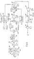
- FIG. 4 shows the experimental set-up used.
- a video source 8 and the appropriate data signal 10 are applied to a video switch 12.
- a switching control unit 14 generates appropriate switching signals so that the data is switched into the video waveform as required.
- the data is generated by a pseudo-random binary sequence generator circuit 16 which produces a square-wave "Boxcar” output after passing through attenuators 15. This is suitably low-pass filtered by a 5.5 MHz group-delay corrected filter 18.
- the data shaping is not a precise cosine law.
- An approximate shaping is achieved using a simple transversal filter 20 with a delay selected expertimentally to produce an optimum eye display when viewed on an oscilloscope.
- the composite video/data waveform is passed through an amplifier 21 to a television modulator 22 and modulated to channel E64 and then attenuated by an attenuator 26 the output of which is then fed at a level of -42 dBm to a Ferguson TX10 receiver uhf input. Sound signals 24 are also fed into the modulator so that any impairment to the sound from the receiver can be assessed.
- a number of adjustments allow the experimental conditions to be varied as appropriate.
- the positions on the screen of the transitions between data and picture are adjustable by means of "Picture Top” and “Picture Bottom” controls 28 and 30 on the switching control unit.
- the PRBS generator provides controls 32, 34 and 36 for the data amplitude, sequence length, and data type (NRZ or Bi-Phase) respectively.
- a variable DC offset 38 is provided to enable the mean DC level of the data to be varied after passing through a differential amplifier 40.
- NRZ or Bi-phase data can therefore, be inserted into television lines with a peak to peak amplitude of 0.3 V with no impairment to existing sound or vision although it is slightly visible.
- the above tests were, however, conducted in a darkened room. In normal lighting conditions the 0.3 V data waveform is virtually invisible, and Bi-phase data is still invisible at 0.4 V peak to peak.
- the optimum form of the data transmitted in the picture area depends on the requirements of the transmission system on which it is to be used. If the mean DC level of the signal is not allowed to fall below black level, as would be the case in a normal TV line, a peak to peak data amplitude of 0.1 V is recommended. If the noise immunity of such signals is found to be insufficient the amplitude of the signal could be increased although this would result in it being visible on some receivers. An amplitude of around 0.3 V is about the maximum before the data signals become annoying in normal viewing conditions. NRZ data can be used in this case, there is no advantage with using Bi-Phase.
- the limit of service area criterion of 64 dB (uV/m) for band 4 and 70 dB(uv/m) for band 5 should achieve a picture to noise ratio of at least 34 dB depending on the receiver. This then implies a margin of about 6 dB in favour of the DATV signal.
- the video signal used by such a transmitter should ideally be generated from an HDTV video signal. It should then be down-converted to reduce the number of active lines to less than the 576 active lines of a conventional 625 line video signal, for example 450 active lines.
- FIG. 5 a block diagram of a proposed transmitter embodying the invention is shown.
- An HDTV camera 42 produces an HDTV signal which forms the input to a standards down-converter processor 44.
- This processor has two outputs. The first output produces picture information on a reduced number of lines (e.g. less than 576 active picture lines for reception on conventional 625 line receivers) and this forms the input to a frame store 46.
- the second output produces digital assistance data for use by HDTV receivers to regenerate the HDTV signal. This data is read into a digital buffer 48.
- TV timing and synchronising waveforms form the input to a controller 50 for the transmitter.
- the clock outputs of the controller enable and disable buffer 48.
- the output data of the digital buffer is coded by a coder 52 which converts it to a form suitable for transmission in the active picture period.
- This data and the picture data output by the frame store are then combined in an adder 54, the combination resulting in either output of picture data or output of coded digital assistance data. This is determined by the enabling and disabling of the frame store 46 and digital buffer 48 output by the controller 50 clock.
- the output signal is the input to a transmitter 53.
- the timing information supplied to the controller 50 is conventional 625 line timing information.
- the controller preferably enables and disables the outputs of the frame store 46 and the digital buffer 48 so that a picture for reception on a conventional receiver is transmitted in the letterbox type format illustrated in Figure 1 and the DATV data invisibly occupies the blank arts of the screen.
- FIG. 6 An HDTV receiver which is compatible with a signal transmitted by the system in Figure 5 is shown in Figure 6.
- the receiver has conventional front end circuitry 54 receiving the signal.
- the output of this circuitry forms the inputs to a data/video switch 56 under the control of a data/video detector 58 which is also connected to the output of the front end circuitry.
- the data/video switch When a signal is received, the data/video switch automatically switches between data and video outputs as either data or video respectively is detected in the incoming signal by the data/video detector 58.
- the picture output of the data/video switch 56 forms the input to a frame store 60 and also supplies timing information to a write controller 62, the output of which controls the storing of picture lines in the frame store 60.
- the data output of the data/video switch forms one of the inputs to a standards up-converter 64, the other input being the output of the frame store 60.
- a clock output from the standards up-converter 64 is used to enable the output of the frame store to release picture information for up-conversion to an HDTV signal with the DATV data. This HDTV signal can then be viewed on an HDTV display 66.
- the above method of transmitting and receiving additional data with extended aspect ratio receivers is intended to be used with any transmission standard.
- the main advantage is that pictures can be transmitted over the same transmission channels as are currently in use and can still be received on conventional receivers.
Abstract
Description
- This invention relates to the transmission of additional data in the active picture period of video transmissions for example such as broadcast television transmission.
- Digitally assisted television (DATV) has been proposed which uses additional data transmitted with a video signal to enhance the display at the receiver and thereby produce, for example, a high definition television (HDTV) picture or some other enhanced display.
- It is proposed that HDTV receivers will typically operate with a larger aspect ratio, namely the ratio of picture width to picture height, than that used with conventional receivers operating, for example, on 625 lines. Since conventional receivers are not compatible with a full bandwidth HDTV signal a method of transmitting signals which can be received on both types of receiver is needed.
- A system for use with both HDTV receivers and conventional receivers is described in US-A-4613903. This uses a high resolution TV camera to provide two transmission signals. The first of these is compatible with a conventional receiver. This signal includes the sum average of two of the HDTV fields in a first field and the remaining HDTV field in a second field. The second signal contains the remaining HDTV information. An HDTV receiver uses both transmitted signals to reconstruct an HDTV signal.
- US-A-4672425 proposes transmitting data in the active picture period of a conventional transmission and using this data to produce an extended aspect ratio picture on a non-conventional receiver. The data is at a level which would be visible when viewed on a conventional receiver. To eliminate visual interference conventional receivers are modified with circuitry to switch the display to constant levels of luminance of chrominance in the picture areas which contain additional data.
- Another system is described in EP-A-0113953. In this an HDTV signal has every other line removed thereby producing a conventional TV signal. The removed lines are then sent as a separate transmission and HDTV receivers need to receive both signals.
- According to one aspect of the present invention there is provided a method of transmitting extended aspect ratio pictures in a video signal comprising the steps of, providing a video signal in which picture information occupies a smaller number of lines than the number required to fill the visible area of a conventional receiver, inserting additional data into at least some of the lines not used for picture information, the data being at a sufficiently low level to be substantially invisible when viewed on a conventional receiver, and transmitting the picture information and data as a conventional video signal.
- According to another aspect of the present invention there is provided a method of transmitting additional data in a video signal comprising the steps of providing a video signal in which picture information occupies less than the whole visible area of a conventional receiver, inserting additional data into at least part of the area not used for picture information, the data being at a sufficiently low level to be substantially invisible when viewed on a conventional receiver, and transmitting the picture information and data as a conventional video signal.
- The present invention also provides apparatus to transmit additional data in a video signal comprising means to provide a first video signal with a first number of lines, means to convert the signal to a second video signal on a reduced number of lines together with data relating to the difference between the two signals, first storage means coupled to a second video signal output of the conversion nears, second storage nears coupled to a data output of the conversion means, combining means coupled to the outputs of the first and second storage means and with an output coupled to the input of a transmitter means, to combine the stored video and data, the data being at a sufficiently low level to be substantially invisible when viewed on a conventional receiver, and control means coupled to the first and second storage means and having a timing information input, to determine whether video signal information from the first storage means or data from the second storage means is available at the combining means inputs.
- Another aspect of the invention provides apparatus to receive a video signal containing additional data within the active picture area, the data being at a sufficiently low level to be substantially invisible when viewed on a conventional receiver, the apparatus comprising input nears to receive the said video signal, switching means responsive to the received signal to switch between a picture output and a data output, storage means to store received picture information under the control of timing information within the said picture information, conversion means coupled to an output of the storage means and to the data output of the switching means to receive picture information from the storage means and to enhance that picture information by generating additional lines of video signal relating to the received additional data, and display means to display the enhanced picture.
- The present invention is defined in the appended claims to which reference should now be made.
- The invention will now be described in more detail by way of example with reference to the drawings, in which:-
- Figure 1 shows an extended aspect ratio picture displayed or a conventional screen;
- Figure 2 shows conventional teletext data and the proposal DATV data format embodying the invention within a picture line;
- Figure 3 shows the proposed DATV data timings in an embodiment of the invention;
- Figure 4 shows an experimental set up to test the system;
- Figure 5 shows a block diagram of a transmitter embodying the invention; and
- Figure 6 shows a block diagram of a receiver embodying the invention.
- The lines in the
blank areas 2 and 4 would now be free to carry other data such as DATV data. However, these free lines are in the visible picture area of a conventional receiver. We have appreciated that it would be highly advantageous to be able to transmit the DATV data in a format which is not easily visible on a conventional receiver and which also does not interfere with the operation of the receiver. For example, the format used for teletext information might be considered. The teletext data levels with respect to black level are shown in Figure 2(a). With standard one volt video the logic levels used for teletext are OV and 0.46V with respect to black level. Thus, if this format is used to transmit data in theblank areas 2 and 4 of a conventional screen, unacceptable patterning will occur. The invention therefore aims to provide data formats which would appear black on a conventional receiver. - We have found that if lower logic levels are used data can then in fact be transmitted in the active picture area without "noisy" effects appearing on the display. The levels should preferably be mostly at or below black level. The signals should also not interfere with the receiver synchronising circuits. One method of ensuring this is to make sure that the sync. circuits see the data as a line of black. This is done by positioning the data levels above and below black so that the mean level is black. This means, however, that the level will go above black level at times. The gamma characteristic of the television tube will, however, ensure that no excessive visibility of the data occurs, provided the data amplitude is not too great.
- The logic levels V1 and V0 can therefore be written as;


Where: 0 = Black level = Mean level of digital signal.
2v = Total peak to peak amplitude of data waveform. - Figure 2(b) shows the total available voltage swing of 0.6V available for the DATV data; however, if the signal is to remain invisible the total swing cannot be used.
- The bit-rate used determines the data capacity provided by each television line, as well as the required channel filtering and required signal to noise ratio. Before specifying the bit rate it is, therefore, ideally necessary to know the required data capacity as well as the service area and the number of lines available for data transmission. The latter is, of course, set by the aspect ratio of the picture. In addition the precise relationship between bit rate and line frequency will have a significant bearing on the appearance of the data if it should be visible. For the purpose of this embodiment a bit rate of around 5.5 MBit/sec is used for NRZ (Non Return to Zero) transmission since with 100% cosine filtering This will conveniently fit within the 5.5 MHz vision bandwidth. Some "Fine-Tuning" has been undertaken to try to minimise the visibility of the data on the screen. This has resulted in a value of 5.50104 MBit/sec, which gives a noise-like appearance with little visible patterning. The bit rate for Bi-Phase transmission is half of this value (2.75052 MBit/sec). Bi-Phase transmission has two transmission bits to transmit each data bit but ensures that the mean of the transmission bits is automatically zero.
- The spectrum of the data signal has a bearing on its visibility. Furthermore, low frequency components around line frequency may cause shifting of the DC level across a line between clamping pulses. This could give rise to a visible streaking effect as well as a reduction of eye-height, and possible sync problems. For this reason several types of data spectrum have been tested:
- a) 32767 Bit pseudo-random sequence NRZ
- b) 32767 Bit pseudo-random sequence BI-PHASE
- c) 127 Bit pseudo-random sequence NRZ
- d) 127 Bit pseudo-random sequence BI-PHASE.
- All four data signals have been inserted at several values of peak to peak amplitude in an experimental arrangement. The mean DC level of the signal was set to black level and tests have been carried out at other D.C. levels to enable the amplitude of the signal to be set higher.
- The data in the tests was inserted in the following lines at the top and bottom of the screen:
- Lines
- 23- 75
Top Field 1
267-310Bottom Field 1
336-388Top Field 2
580-623Bottom Field 2 - It is necessary to leave the colour bursts in the data lines in order to avoid incorrect operation giving rise to a colour flashing effect at the top of the active picture. To provide for this, the data is disabled during line blanking, and thus extends from 10.35 us after the leading edge of syncs to 1.7 s before the next sync as shown in Figure 3.
- The above figures relate to a conventional 625/50 PAL signal as is broadcast in the United Kingdom, having a line period of 64 us.
- Figure 4 shows the experimental set-up used. A
video source 8 and the appropriate data signal 10 are applied to avideo switch 12. A switchingcontrol unit 14 generates appropriate switching signals so that the data is switched into the video waveform as required. The data is generated by a pseudo-random binarysequence generator circuit 16 which produces a square-wave "Boxcar" output after passing throughattenuators 15. This is suitably low-pass filtered by a 5.5 MHz group-delay correctedfilter 18. For the purpose of this investigation the data shaping is not a precise cosine law. An approximate shaping is achieved using a simpletransversal filter 20 with a delay selected expertimentally to produce an optimum eye display when viewed on an oscilloscope. - The composite video/data waveform is passed through an
amplifier 21 to atelevision modulator 22 and modulated to channel E64 and then attenuated by anattenuator 26 the output of which is then fed at a level of -42 dBm to a Ferguson TX10 receiver uhf input. Sound signals 24 are also fed into the modulator so that any impairment to the sound from the receiver can be assessed. - A number of adjustments allow the experimental conditions to be varied as appropriate. The positions on the screen of the transitions between data and picture are adjustable by means of "Picture Top" and "Picture Bottom" controls 28 and 30 on the switching control unit. Similarly the PRBS generator provides
controls differential amplifier 40. - Data waveforms centred on black level appear to be the most suitable for insertion into blank lines. Four values of peak to peak data amplitude have been tried:
- a) 0.3 V (colour burst amplitude)
- b) 0.4 V
- c) 0.5 V
- d) 0.6 V
- a) The visibility of the data waveform on the blanked off part of the screen, expressed as an approximate grade on a CCIR 5-point impairment scale (see Appendix).
- b) The extent of any synchronisation problems, and whether or not data can be inserted in field blanking.
- c) Any impairments to the active picture area.
- d) Any impairments to the sound.
- The results are set out in TABLE 1 below,
TABLE 1 Peak-peak amplitude of data (V) 0.3 0.4 0.5 0.6 32767-Bit sequence NRZ Visibility of data 4 2.5 2 1 Sync Stability O.K. O.K. O.K. O.K. 32767-Bit sequence Bi-Phase Visibility of data 4 3 2 1 Sync Stability O.K. O.K. O.K. O.K. 127-Bit sequence NRZ Visibility of data 3 1 1 1 Sync Stability O.K. O.K. O.K. O.K. 127-Bit sequence Bi-Phase Visibility of data 4 2 1 1 Sync Stability O.K. O.K. O.K. O.K.
No impairments to sound or active picture were perceptible for any of the test cases. - NRZ or Bi-phase data can therefore, be inserted into television lines with a peak to peak amplitude of 0.3 V with no impairment to existing sound or vision although it is slightly visible. The above tests were, however, conducted in a darkened room. In normal lighting conditions the 0.3 V data waveform is virtually invisible, and Bi-phase data is still invisible at 0.4 V peak to peak.
- A further test has been carried out involving setting the data amplitude to zero and increasing it until it becomes visible. As before the experiment was conducted in a darkened room. It was found that on the TX10 receiver, in order to be completely invisible the amplitude of the data must be no greater than 0.16 V (0.08 V above and below black level). The same result was obtained with both pseudo-random sequences, NRZ and Bi-phase. Furthermore, on a JVC portable monitor receiver the amplitude needs to be 0.1 V (0.05 V above and below black level).
- From this it seems that although a reasonable data amplitude can be used in normal viewing conditions, in a darkened room the amplitude must be reduced to 0.1 V if it is to be completely invisible on the two receivers tried with the data centred on black level.
- The use of data waveforms with the mean DC level below black level has been tested with three domestic receivers.
- a) A Ferguson TX10
- b) A JVC Portable Receiver/Monitor Model CX6 10GB
- c) A Decca Receiver/Monitor Model CS2645/AL.
- i) The top of the waveform excursions is limited by the degree of visibility
- ii) The bottom of the waveform excursions is limited by failure of the receiver synchronising circuits
- The sync stability seems, in general, to be worse with uhf signals. The visibility is generally better with uhf signals.
- The optimum form of the data transmitted in the picture area depends on the requirements of the transmission system on which it is to be used. If the mean DC level of the signal is not allowed to fall below black level, as would be the case in a normal TV line, a peak to peak data amplitude of 0.1 V is recommended. If the noise immunity of such signals is found to be insufficient the amplitude of the signal could be increased although this would result in it being visible on some receivers. An amplitude of around 0.3 V is about the maximum before the data signals become annoying in normal viewing conditions. NRZ data can be used in this case, there is no advantage with using Bi-Phase.
- All receivers tested, however, will tolerate a mean DC level below black level. If this is allowable from the point of view of the transmission system a NRZ signal between -0.19 V and 0.07 V should be possible, providing an amplitude of 0.26 V. It is recommended, however, that if possible Bi-Phase coding is used. This does not prove as disturbing to receiver sync circuits and allows the lower level to be set to -0.26 V providing an amplitude of 0.33 V. This, of course, depends on whether the proposed aspect ratio allows for sufficient data lines to be able to stand the resulting reduction in bit rate.
- The above data amplitudes are less than the 0.46 V amplitude of the Teletext system. Although the data rate is different from that used for these tests, early work on Teletext has shown very little difference in noise performance over the range 4.5 MBit/s to 6.875 MBit/s. Consequently results obtained for Teletext may for the present be used to estimate the expected noise margins with the new DATV signal. Field tests on Teletext suggest that failure occurs when the ratio of picture to RMS noise is around 23 dB. From this it may be deduced that the proposed DATV data should fail at about 28 dB. For an acceptable television picture it is necessary to achieve a signal to noise ratio of at least 30 dB, so from this point of view the 0.26 V amplitude should be sufficient. Furthermore, the limit of service area criterion of 64 dB (uV/m) for band 4 and 70 dB(uv/m) for band 5 should achieve a picture to noise ratio of at least 34 dB depending on the receiver. This then implies a margin of about 6 dB in favour of the DATV signal.
- In a real transmitter, an arrangement similar to Figure 4 could be used. Instead of a pseudo random
binary sequence generator 16, a source of real data would be used, in the case of a DATV transmission this would initially be extracted from picture information. The PALcolour bar generator 8 would be replaced by a video signal and the transmitter would be switched between video and data by thevideo switch 12 under control of the switchingcontrol unit 14. - The video signal used by such a transmitter should ideally be generated from an HDTV video signal. It should then be down-converted to reduce the number of active lines to less than the 576 active lines of a conventional 625 line video signal, for example 450 active lines.
- In Figure 5 a block diagram of a proposed transmitter embodying the invention is shown. An HDTV camera 42 produces an HDTV signal which forms the input to a standards down-
converter processor 44. This processor has two outputs. The first output produces picture information on a reduced number of lines (e.g. less than 576 active picture lines for reception on conventional 625 line receivers) and this forms the input to aframe store 46. The second output produces digital assistance data for use by HDTV receivers to regenerate the HDTV signal. This data is read into adigital buffer 48. - TV timing and synchronising waveforms form the input to a
controller 50 for the transmitter. The clock outputs of the controller enable and disablebuffer 48. The output data of the digital buffer is coded by acoder 52 which converts it to a form suitable for transmission in the active picture period. This data and the picture data output by the frame store are then combined in anadder 54, the combination resulting in either output of picture data or output of coded digital assistance data. This is determined by the enabling and disabling of theframe store 46 anddigital buffer 48 output by thecontroller 50 clock. The output signal is the input to atransmitter 53. - The timing information supplied to the
controller 50 is conventional 625 line timing information. The controller preferably enables and disables the outputs of theframe store 46 and thedigital buffer 48 so that a picture for reception on a conventional receiver is transmitted in the letterbox type format illustrated in Figure 1 and the DATV data invisibly occupies the blank arts of the screen. - An HDTV receiver which is compatible with a signal transmitted by the system in Figure 5 is shown in Figure 6. The receiver has conventional
front end circuitry 54 receiving the signal. The output of this circuitry forms the inputs to a data/video switch 56 under the control of a data/video detector 58 which is also connected to the output of the front end circuitry. - When a signal is received, the data/video switch automatically switches between data and video outputs as either data or video respectively is detected in the incoming signal by the data/
video detector 58. - The picture output of the data/
video switch 56 forms the input to aframe store 60 and also supplies timing information to awrite controller 62, the output of which controls the storing of picture lines in theframe store 60. The data output of the data/video switch forms one of the inputs to a standards up-converter 64, the other input being the output of theframe store 60. A clock output from the standards up-converter 64 is used to enable the output of the frame store to release picture information for up-conversion to an HDTV signal with the DATV data. This HDTV signal can then be viewed on anHDTV display 66. - The above method of transmitting and receiving additional data with extended aspect ratio receivers is intended to be used with any transmission standard. The main advantage is that pictures can be transmitted over the same transmission channels as are currently in use and can still be received on conventional receivers.


Therefore, for the sample receivers tested the maximum data signals that can be inserted are:
NRZ long sequence -0.19 to 0.08 V (Peak-Peak = 0.27V)
NRZ short sequence -0.19 to 0.07 V (Peak-Peak = 0.26 V)
Bi-Phase long sequence -0.26 to 0.08 V (Peak-Peak = 0.34 V)
Bi-Phase short sequence -0.26 to 0.07 V (Peak-Peak = 0.33 V)
From the point of view of sync stability all three receivers perform much the same. Even the Decca receiver which is of fairly old design is not significantly less tolerant to data signals than the two modern sets. In the case of the visibility of data above black level the TX10 starts to show signals at only 0.07 V, whereas the Decca receiver can take NRZ up to 0.22 V without it showing up. This can be explained by the higher brightness of the modem PIL tube in the TX10 compared with that of the old delta tube in the Decca receiver.
Claims (14)
- A method of transmitting additional data in a video signal comprising the steps of providing a video signal in which picture information occupies less than the whole visible area of a conventional receiver, providing additional data, inserting the additional data into at least part of the visible area not used for picture information, transmitting the picture information and data as a conventional video signal characterised in that the data is provided and inserted into the visible area at a sufficiently low level to be substantially invisible when viewed on a conventional receiver.
- A method according to claim 1 characterised in that the additional data is inserted between consecutive line blanking periods.
- A method according to claim 1 or 2 characterised in that the mean D.C. level of the additional data is substantially at black level.
- A method according to claim 3 characterised in that the ratio of peak-to-peak amplitudes of the additional data to the video signal is no greater than 0.3:1.
- A method according to claim 1 or 2 characterised in that the mean D.C. level of the additional data is below black level.
- A method according to claim 5 characterised in that the additional data is of the non return to zero type.
- A method according to claim 1 or 2 characterised in that the additional data is of the Bi-phase type.
- A method according to any preceding claim characterised in that the additional data is digital data.
- A method according to any preceding claim characterised in that the additional data is data to enhance display quality on HDTV receivers.
- Apparatus to transmit additional data in a video signal comprising means (42) to provide a first video signal with a first number of lines, means (44) to convert the signal to a second video signal on a reduced number of lines toegether with data relating to the difference between the two signals, first storage (46) means coupled to a video signal output of the conversion means, second storage means (48, 52) coupled to a data output of the conversion means, combining means (54) coupled to the outputs of the first and second storage means and with an output coupled to the input of a transmitter means (53), to combine the stored video and data, and control means (50) coupled to the first and second storage means and having a timing information input, to determine whether video signal information from the first storage means or data from the second storage means is available at the combining means inputs characterised in that the data is combined with the video signal at a sufficiently low level to be substantially invisible when viewed on a conventional receiver.
- Apparatus according to claim 10 in which the first video signal is a high definition (HDTV) signal.
- Apparatus according to claim 10 or 11 in which the data relating to the difference between the two signals is digital assistance data.
- Apparatus according to claim 10, 11 or 12 in which the transmitted signal is a 625 line video signal.
- Apparatus to receive a conventional video signal containing additional data within the active picture area, the apparatus comprising input means (54) to receive the said video signal, switching means (56) responsive to the received signal to switch between a picture output and a data output, storage means (60) to store received picture information under the control of timing information with the said picture information, conversion means (64) coupled to an output of the storage means and to the data output of the switching means to receive picture information from the storage means and to enhance that picture information by generating additional lines of video signal relating to the received additional data, and display means (66) to display the enhanced picture characterised in that the received data is at a sufficiently low level to be substantially invisible when viewed on a conventional receiver and the switching means is responsive to the data at such a level.
Priority Applications (1)
| Application Number | Priority Date | Filing Date | Title |
|---|---|---|---|
| AT89900617T ATE102422T1 (en) | 1987-12-07 | 1989-06-22 | DATA TRANSMISSION IN ACTIVE FRAME PERIOD. |
Applications Claiming Priority (4)
| Application Number | Priority Date | Filing Date | Title |
|---|---|---|---|
| GB878728530A GB8728530D0 (en) | 1987-12-07 | 1987-12-07 | Data transmission in active picture period |
| GB8728530 | 1987-12-07 | ||
| GB8729000 | 1987-12-11 | ||
| GB8729000A GB2213342B (en) | 1987-12-07 | 1987-12-11 | Data transmission in active picture period |
Publications (2)
| Publication Number | Publication Date |
|---|---|
| EP0345326A1 EP0345326A1 (en) | 1989-12-13 |
| EP0345326B1 true EP0345326B1 (en) | 1994-03-02 |
Family
ID=26293167
Family Applications (1)
| Application Number | Title | Priority Date | Filing Date |
|---|---|---|---|
| EP89900617A Revoked EP0345326B1 (en) | 1987-12-07 | 1989-06-22 | Data transmission in active picture period |
Country Status (5)
| Country | Link |
|---|---|
| US (1) | US5075773A (en) |
| EP (1) | EP0345326B1 (en) |
| JP (1) | JPH02502508A (en) |
| DE (1) | DE3888169T2 (en) |
| WO (1) | WO1989005555A1 (en) |
Families Citing this family (61)
| Publication number | Priority date | Publication date | Assignee | Title |
|---|---|---|---|---|
| DE3841173C1 (en) * | 1988-12-07 | 1989-11-16 | Institut Fuer Rundfunktechnik Gmbh, 8000 Muenchen, De | Compatible television transmission system |
| JP2712674B2 (en) * | 1989-12-18 | 1998-02-16 | 松下電器産業株式会社 | Transmission method of wide television signal |
| DE3942570A1 (en) * | 1989-12-22 | 1991-07-04 | Inst Rundfunktechnik Gmbh | METHOD FOR TRANSMITTING DIGITAL INFORMATION, IN PARTICULAR SOUND INFORMATION, IN A TELEVISION CHANNEL |
| DE4020066A1 (en) * | 1990-06-23 | 1992-01-09 | Inst Rundfunktechnik Gmbh | Transmission and decoding system for video data signals |
| US5278649A (en) * | 1991-01-22 | 1994-01-11 | Matsushita Electric Corporation Of America | Method and apparatus for transmission of signals for an extended definition television system |
| JPH0575976A (en) * | 1991-01-22 | 1993-03-26 | Matsushita Electric Ind Co Ltd | Television signal transmitter |
| DE4112712A1 (en) * | 1991-04-18 | 1992-10-22 | Inst Rundfunktechnik Gmbh | Compatible transmission of television signal mode additional information |
| US5200822A (en) * | 1991-04-23 | 1993-04-06 | National Broadcasting Company, Inc. | Arrangement for and method of processing data, especially for identifying and verifying airing of television broadcast programs |
| US5617148A (en) * | 1991-06-14 | 1997-04-01 | Wavephore, Inc. | Filter by-pass for transmitting an additional signal with a video signal |
| US5559559A (en) * | 1991-06-14 | 1996-09-24 | Wavephore, Inc. | Transmitting a secondary signal with dynamic injection level control |
| US5831679A (en) * | 1991-06-14 | 1998-11-03 | Wavephore, Inc. | Network for retrieval and video transmission of information |
| US5410360A (en) * | 1991-06-14 | 1995-04-25 | Wavephore, Inc. | Timing control for injecting a burst and data into a video signal |
| US5387941A (en) * | 1991-06-14 | 1995-02-07 | Wavephore, Inc. | Data with video transmitter |
| US5327237A (en) * | 1991-06-14 | 1994-07-05 | Wavephore, Inc. | Transmitting data with video |
| JPH0822057B2 (en) * | 1992-04-21 | 1996-03-04 | 松下電器産業株式会社 | Television signal processing method and processing apparatus |
| US5721788A (en) | 1992-07-31 | 1998-02-24 | Corbis Corporation | Method and system for digital image signatures |
| US6301369B2 (en) | 1992-07-31 | 2001-10-09 | Digimarc Corporation | Image marking to permit later identification |
| US5408270A (en) * | 1993-06-24 | 1995-04-18 | Massachusetts Institute Of Technology | Advanced television system |
| US6122403A (en) | 1995-07-27 | 2000-09-19 | Digimarc Corporation | Computer system linked by using information in data objects |
| US6408082B1 (en) | 1996-04-25 | 2002-06-18 | Digimarc Corporation | Watermark detection using a fourier mellin transform |
| US5862260A (en) * | 1993-11-18 | 1999-01-19 | Digimarc Corporation | Methods for surveying dissemination of proprietary empirical data |
| EP0987855A2 (en) * | 1993-11-18 | 2000-03-22 | Digimarc Corporation | Method and apparatus for encoding audio with auxiliary digital data |
| US6611607B1 (en) | 1993-11-18 | 2003-08-26 | Digimarc Corporation | Integrating digital watermarks in multimedia content |
| US5768426A (en) | 1993-11-18 | 1998-06-16 | Digimarc Corporation | Graphics processing system employing embedded code signals |
| US6516079B1 (en) | 2000-02-14 | 2003-02-04 | Digimarc Corporation | Digital watermark screening and detecting strategies |
| US5841886A (en) * | 1993-11-18 | 1998-11-24 | Digimarc Corporation | Security system for photographic identification |
| US5832119C1 (en) * | 1993-11-18 | 2002-03-05 | Digimarc Corp | Methods for controlling systems using control signals embedded in empirical data |
| US6757406B2 (en) | 1993-11-18 | 2004-06-29 | Digimarc Corporation | Steganographic image processing |
| US5822436A (en) | 1996-04-25 | 1998-10-13 | Digimarc Corporation | Photographic products and methods employing embedded information |
| US5748783A (en) * | 1995-05-08 | 1998-05-05 | Digimarc Corporation | Method and apparatus for robust information coding |
| US6983051B1 (en) | 1993-11-18 | 2006-01-03 | Digimarc Corporation | Methods for audio watermarking and decoding |
| US7171016B1 (en) | 1993-11-18 | 2007-01-30 | Digimarc Corporation | Method for monitoring internet dissemination of image, video and/or audio files |
| US6580819B1 (en) | 1993-11-18 | 2003-06-17 | Digimarc Corporation | Methods of producing security documents having digitally encoded data and documents employing same |
| USRE40919E1 (en) * | 1993-11-18 | 2009-09-22 | Digimarc Corporation | Methods for surveying dissemination of proprietary empirical data |
| US6424725B1 (en) | 1996-05-16 | 2002-07-23 | Digimarc Corporation | Determining transformations of media signals with embedded code signals |
| US6614914B1 (en) | 1995-05-08 | 2003-09-02 | Digimarc Corporation | Watermark embedder and reader |
| US5748763A (en) | 1993-11-18 | 1998-05-05 | Digimarc Corporation | Image steganography system featuring perceptually adaptive and globally scalable signal embedding |
| JP2554450B2 (en) * | 1993-12-16 | 1996-11-13 | 日本テレビ放送網株式会社 | Frame synchronizer and signal switching device using the same |
| US6522770B1 (en) | 1999-05-19 | 2003-02-18 | Digimarc Corporation | Management of documents and other objects using optical devices |
| WO1995029558A1 (en) * | 1994-04-20 | 1995-11-02 | Shoot The Moon Products, Inc. | Method and apparatus for nesting secondary signals within a television signal |
| USRE44685E1 (en) | 1994-04-28 | 2013-12-31 | Opentv, Inc. | Apparatus for transmitting and receiving executable applications as for a multimedia system, and method and system to order an item using a distributed computing system |
| US6560349B1 (en) | 1994-10-21 | 2003-05-06 | Digimarc Corporation | Audio monitoring using steganographic information |
| US6728390B2 (en) | 1995-05-08 | 2004-04-27 | Digimarc Corporation | Methods and systems using multiple watermarks |
| US6721440B2 (en) | 1995-05-08 | 2004-04-13 | Digimarc Corporation | Low visibility watermarks using an out-of-phase color |
| US6760463B2 (en) | 1995-05-08 | 2004-07-06 | Digimarc Corporation | Watermarking methods and media |
| US5771073A (en) * | 1995-06-07 | 1998-06-23 | Massachusetts Institute Of Technology | Advanced television system using a different encoding technique for non-image areas |
| US6577746B1 (en) | 1999-12-28 | 2003-06-10 | Digimarc Corporation | Watermark-based object linking and embedding |
| US6788800B1 (en) | 2000-07-25 | 2004-09-07 | Digimarc Corporation | Authenticating objects using embedded data |
| US6829368B2 (en) | 2000-01-26 | 2004-12-07 | Digimarc Corporation | Establishing and interacting with on-line media collections using identifiers in media signals |
| US6189030B1 (en) | 1996-02-21 | 2001-02-13 | Infoseek Corporation | Method and apparatus for redirection of server external hyper-link references |
| US6381341B1 (en) | 1996-05-16 | 2002-04-30 | Digimarc Corporation | Watermark encoding method exploiting biases inherent in original signal |
| US5903231A (en) * | 1996-12-16 | 1999-05-11 | Vidicast Ltd. | System for encoding base N data using a multi-level coding scheme |
| US6122010A (en) * | 1996-12-16 | 2000-09-19 | Vidicast Ltd. | Television signal data transmission system |
| US6850626B2 (en) | 1998-01-20 | 2005-02-01 | Digimarc Corporation | Methods employing multiple watermarks |
| US6625297B1 (en) | 2000-02-10 | 2003-09-23 | Digimarc Corporation | Self-orienting watermarks |
| US6804377B2 (en) | 2000-04-19 | 2004-10-12 | Digimarc Corporation | Detecting information hidden out-of-phase in color channels |
| US7057666B2 (en) * | 2000-10-24 | 2006-06-06 | Harris Corporation | System and method for encoding information into a video signal |
| JP2002262246A (en) * | 2001-03-05 | 2002-09-13 | Mitsubishi Electric Corp | Device and method for controlling output information |
| US8400569B2 (en) * | 2004-11-30 | 2013-03-19 | Broadcom Corporation | Video system and method supporting display of different size pictures |
| JP4561482B2 (en) * | 2005-06-01 | 2010-10-13 | 株式会社日立製作所 | Video display device |
| EP2107806A1 (en) * | 2008-03-31 | 2009-10-07 | Harman Becker Automotive Systems GmbH | Transmitting video and additional information using the image transmission area of a transmission signal |
Family Cites Families (10)
| Publication number | Priority date | Publication date | Assignee | Title |
|---|---|---|---|---|
| JPS56157871U (en) * | 1980-04-25 | 1981-11-25 | ||
| GB2132444A (en) * | 1982-12-22 | 1984-07-04 | Phillips Electronic And Associ | Television transmission system |
| US4556906A (en) * | 1983-11-15 | 1985-12-03 | Rca Corporation | Kinescope blanking scheme for wide-aspect ratio television |
| US4613903A (en) * | 1984-04-06 | 1986-09-23 | North American Philips Corporation | High-resolution television transmission system |
| FR2567349B1 (en) * | 1984-07-03 | 1986-12-12 | Labo Electronique Physique | MAC-TYPE TELEVISION SYSTEM ADAPTED FOR BROADCASTING 5/3 FORMAT IMAGES, INTERFACE DEVICE BETWEEN THIS SYSTEM AND 4/3 FORMAT RECEIVERS, AND TELEVISION RECEIVER EQUIPPED WITH SUCH A DEVICE |
| GB8602644D0 (en) * | 1986-02-04 | 1986-03-12 | British Broadcasting Corp | Video systems |
| WO1987005769A1 (en) * | 1986-03-19 | 1987-09-24 | British Broadcasting Corporation | Tv picture motion measurement |
| US4855827A (en) * | 1987-07-21 | 1989-08-08 | Worlds Of Wonder, Inc. | Method of providing identification, other digital data and multiple audio tracks in video systems |
| IT1215909B (en) * | 1988-02-18 | 1990-02-22 | Rai Radiotelevisione Italiana | PROCEDURE FOR THE GENERATION AND TRANSMISSION OF HIGH-DEFINITION COLOR TELEVISION SIGNALS COMPATIBLE WITH THE CURRENT STANDARDS AND PROCEDURE AND RECEIVING EQUIPMENT FOR SIGNALS. |
| US4959717A (en) * | 1989-05-12 | 1990-09-25 | Faroudja Y C | Method for masking picture reinforcement signals carried within the vertical interval |
-
1988
- 1988-12-05 JP JP1500387A patent/JPH02502508A/en active Pending
- 1988-12-05 DE DE3888169T patent/DE3888169T2/en not_active Revoked
- 1988-12-05 US US07/382,641 patent/US5075773A/en not_active Expired - Fee Related
- 1988-12-05 WO PCT/GB1988/001059 patent/WO1989005555A1/en not_active Application Discontinuation
-
1989
- 1989-06-22 EP EP89900617A patent/EP0345326B1/en not_active Revoked
Also Published As
| Publication number | Publication date |
|---|---|
| EP0345326A1 (en) | 1989-12-13 |
| WO1989005555A1 (en) | 1989-06-15 |
| US5075773A (en) | 1991-12-24 |
| DE3888169T2 (en) | 1994-06-09 |
| JPH02502508A (en) | 1990-08-09 |
| DE3888169D1 (en) | 1994-04-07 |
Similar Documents
| Publication | Publication Date | Title |
|---|---|---|
| EP0345326B1 (en) | Data transmission in active picture period | |
| US5557333A (en) | System for transparent transmission and reception of a secondary data signal with a video signal in the video band | |
| US5666168A (en) | System for transmitting facsimile data in the upper vestigial chrominance sideband of a video signal | |
| US5831679A (en) | Network for retrieval and video transmission of information | |
| US5410360A (en) | Timing control for injecting a burst and data into a video signal | |
| WO1990009081A1 (en) | A receiver-compatible enhanced definition television system | |
| US4458268A (en) | Sync displacement scrambling | |
| US4646135A (en) | System for allowing two television programs simultaneously to use the normal bandwidth for one program by chrominance time compression and luminance bandwidth reduction | |
| US4335402A (en) | Information transmission during first-equalizing pulse interval in television | |
| US4516151A (en) | Color slow scan video signal translation | |
| ES2010626A6 (en) | Extended definition widescreen television system using plural signal transmission channels. | |
| US4847676A (en) | Color television system | |
| GB2213342A (en) | Digital assistance data transmission in active picture period | |
| EP0124222B1 (en) | Monochrome-compatible color slow scan television system | |
| US5202755A (en) | Encoding system of a simulcast high definition television and method thereof | |
| GB2250889A (en) | Receiver for DATV data transmitted in active picture period | |
| EP0451205B1 (en) | Television transmission system compatible with conventional television standards | |
| EP0510973A1 (en) | Television signal processing apparatus | |
| US5278649A (en) | Method and apparatus for transmission of signals for an extended definition television system | |
| EP0361565A2 (en) | High-definition television with frequency multiplexing | |
| US4811095A (en) | Arrangement for displaying multiplexed analog components on a conventional TV monitor | |
| GB2213341A (en) | Transmitting digitally assisted television data signals | |
| JPS60192A (en) | Processing system in receiver of color television signal of secam type | |
| JPS5948595B2 (en) | Color television signal transmission system | |
| Gardiner | Echo cancelling |
Legal Events
| Date | Code | Title | Description |
|---|---|---|---|
| PUAI | Public reference made under article 153(3) epc to a published international application that has entered the european phase |
Free format text: ORIGINAL CODE: 0009012 |
|
| AK | Designated contracting states |
Kind code of ref document: A1 Designated state(s): AT BE CH DE FR IT LI LU NL SE |
|
| 17P | Request for examination filed |
Effective date: 19891214 |
|
| 17Q | First examination report despatched |
Effective date: 19920327 |
|
| GRAA | (expected) grant |
Free format text: ORIGINAL CODE: 0009210 |
|
| AK | Designated contracting states |
Kind code of ref document: B1 Designated state(s): AT BE CH DE FR IT LI LU NL SE |
|
| REF | Corresponds to: |
Ref document number: 102422 Country of ref document: AT Date of ref document: 19940315 Kind code of ref document: T |
|
| ITF | It: translation for a ep patent filed |
Owner name: BARZANO' E ZANARDO ROMA S.P.A. |
|
| REF | Corresponds to: |
Ref document number: 3888169 Country of ref document: DE Date of ref document: 19940407 |
|
| ET | Fr: translation filed | ||
| PGFP | Annual fee paid to national office [announced via postgrant information from national office to epo] |
Ref country code: FR Payment date: 19940930 Year of fee payment: 7 |
|
| PG25 | Lapsed in a contracting state [announced via postgrant information from national office to epo] |
Ref country code: AT Effective date: 19941201 |
|
| PLBI | Opposition filed |
Free format text: ORIGINAL CODE: 0009260 |
|
| PG25 | Lapsed in a contracting state [announced via postgrant information from national office to epo] |
Ref country code: SE Effective date: 19941206 |
|
| PG25 | Lapsed in a contracting state [announced via postgrant information from national office to epo] |
Ref country code: LU Free format text: LAPSE BECAUSE OF NON-PAYMENT OF DUE FEES Effective date: 19941231 Ref country code: LI Free format text: LAPSE BECAUSE OF NON-PAYMENT OF DUE FEES Effective date: 19941231 Ref country code: CH Free format text: LAPSE BECAUSE OF NON-PAYMENT OF DUE FEES Effective date: 19941231 Ref country code: BE Effective date: 19941231 |
|
| 26 | Opposition filed |
Opponent name: LOEWE OPTA GMBH Effective date: 19941201 |
|
| EAL | Se: european patent in force in sweden |
Ref document number: 89900617.5 |
|
| PGFP | Annual fee paid to national office [announced via postgrant information from national office to epo] |
Ref country code: DE Payment date: 19950222 Year of fee payment: 7 |
|
| NLR1 | Nl: opposition has been filed with the epo |
Opponent name: LOEWE OPTA GMBH |
|
| BERE | Be: lapsed |
Owner name: BRITISH BROADCASTING CORP. Effective date: 19941231 |
|
| PG25 | Lapsed in a contracting state [announced via postgrant information from national office to epo] |
Ref country code: NL Effective date: 19950701 |
|
| REG | Reference to a national code |
Ref country code: CH Ref legal event code: PL |
|
| NLV4 | Nl: lapsed or anulled due to non-payment of the annual fee |
Effective date: 19950701 |
|
| EUG | Se: european patent has lapsed |
Ref document number: 89900617.5 |
|
| RDAG | Patent revoked |
Free format text: ORIGINAL CODE: 0009271 |
|
| STAA | Information on the status of an ep patent application or granted ep patent |
Free format text: STATUS: PATENT REVOKED |
|
| 27W | Patent revoked |
Effective date: 19950911 |