EP0342945A2 - Implantable patient-activated fluid delivery device and outlet valve therefor - Google Patents
Implantable patient-activated fluid delivery device and outlet valve therefor Download PDFInfo
- Publication number
- EP0342945A2 EP0342945A2 EP89304967A EP89304967A EP0342945A2 EP 0342945 A2 EP0342945 A2 EP 0342945A2 EP 89304967 A EP89304967 A EP 89304967A EP 89304967 A EP89304967 A EP 89304967A EP 0342945 A2 EP0342945 A2 EP 0342945A2
- Authority
- EP
- European Patent Office
- Prior art keywords
- valve
- valve member
- fluid
- outlet
- seat
- Prior art date
- Legal status (The legal status is an assumption and is not a legal conclusion. Google has not performed a legal analysis and makes no representation as to the accuracy of the status listed.)
- Withdrawn
Links
Images


Classifications
-
- A—HUMAN NECESSITIES
- A61—MEDICAL OR VETERINARY SCIENCE; HYGIENE
- A61M—DEVICES FOR INTRODUCING MEDIA INTO, OR ONTO, THE BODY; DEVICES FOR TRANSDUCING BODY MEDIA OR FOR TAKING MEDIA FROM THE BODY; DEVICES FOR PRODUCING OR ENDING SLEEP OR STUPOR
- A61M5/00—Devices for bringing media into the body in a subcutaneous, intra-vascular or intramuscular way; Accessories therefor, e.g. filling or cleaning devices, arm-rests
- A61M5/14—Infusion devices, e.g. infusing by gravity; Blood infusion; Accessories therefor
- A61M5/142—Pressure infusion, e.g. using pumps
- A61M5/14244—Pressure infusion, e.g. using pumps adapted to be carried by the patient, e.g. portable on the body
- A61M5/14276—Pressure infusion, e.g. using pumps adapted to be carried by the patient, e.g. portable on the body specially adapted for implantation
- A61M5/1428—Pressure infusion, e.g. using pumps adapted to be carried by the patient, e.g. portable on the body specially adapted for implantation with manual pumping action
Definitions
- Implantable devices have been disclosed in the prior art that may be activated by ambulatory patients when the administration of measured doses of therapeutic agents is required.
- cancer patients suffering from terminal lower torso cancer may require routine injections of morphine, either epidurally or intrathecally, and, upon receiving such injections, are sufficiently relieved of the symptoms of pain to move about and perform many routine and normal functions.
- Other chronic ailments also require frequent dosages of therapeutic agents in the treatment of chronic conditions, such as insulin in the case of diabetes.
- Implantable devices capable of delivering measured amounts of medicament on demand are disclosed in United States patents 4,634,427, 4,548,607, 4,588,394, 4,557,722, 4,544,371, and 4,543,088.
- the fluid delivery device of this invention is formed of soft and deformable (preferably elastomeric) material capable of being worn comfortably and effectively in implanted condition over an extended period.
- the device has a relatively rigid internal structure that serves to support various operative elements, such support also performing the functions of distributing pumping forces produced by finger pressure and protecting the casing (as well as interior elements) against damage and possible leakage during refilling operations.
- top wall has a central target zone that may be easily located by touch (even when the device is implanted) and that serves as both the pump-actuating site against which finger pressure is exerted when drug delivery is needed and as the site for medicament injection when refilling of the reservoir is required.
- fluid pressure equalization within the device insures that pump activation and drug delivery do not occur unless directed and localized force is applied specifically to the target zone -- a force that can be expected to be applied only intentionally.
- valve mechanism of the system resists activation until the locally-applied force reaches a predetermined magnitude. Unless a selected force within a range of, say, 10 to 20 pounds per square inch is applied to the central target zone of the device's top wall, the outlet valve will remain in closed condition. Of further significance is the fact that when sufficient localized force is so applied, the outlet valve will break open with sufficient suddenness and completeness to provide tactile feedback to the user. Through a sense of touch, a user may therefore determine that the device has indeed been activated and a metered amount of medicament has been discharged.
- the implantable fluid delivery device includes a casing formed of soft, deformable polymeric material, preferably elastomeric material, having top and bottom walls defining a fluid reservoir therebetween.
- a rigid support plate is disposed within the casing and divides the reservoir into upper and lower chambers that communicate with each other through an opening in the plate.
- Compressible pumping means is mounted upon the plate within the upper chamber and includes a deformable pump housing that defines a pump cavity with a first passage connecting that cavity with the lower chamber of the reservoir.
- a second passage connects the same cavity with the outlet port of the device, and check valves are positioned to control flow through the respective passages.
- the top wall of the casing includes a flexible pump-actuating zone.
- Connecting means in the form of a self-sealing septum combined with a rigid cover plate operatively connect the top wall's pump actuating zone with the pump housing.
- the self-sealing properties of the piercable septum are enhanced by a construction that maintains that septum in a partially-compressed state.
- the casing and many of the components contained within it are readily deformable, being formed of silicone rubber or other suitable material and although build up of fluid pressure due to unexpected compressive loads on the device is possible, pressure equalization within the reservoir, on opposite sides of elements such as the deformable pump housing and the check valve for the second passage, insure that deformation of the casing will not result in fluid delivery unless such deformation specifically includes depression of the target zone of the top wall in the direction of the compressible pump.
- a porous metal filter is mounted upon the support plate at the entry to the first passage leading from the reservoir to the pump cavity.
- the filter also performs a rate controlling function and therefore prevents surges of fluid, produced by compressive deformation of the device's deformable casing, that might otherwise cause damage to the pump assembly.
- Channel-defining ribs within the reservoir also function to equalize pressure within that reservoir and prevent obstructive contact with the rigid filter that might block fluid flow to the pump cavity.
- the outlet valve which functions as a check valve in the second (outlet) passage, is cup-shaped with a lower surface that cooperates with the flexible annular lip of the valve seat to maintain the valve in sealed condition throughout early stages in the deformation of the valve member as it moves towards an open condition.
- a sharp breakway occurs when the flexible lip reaches its limit of deformation and the valve member proceeds to its fully open position, at which time the breakway action and sudden release of pressure offer tactile feedback to the patient, signalling that a measured volume of medicament has been (or is being) discharged by the device.
- the numeral 10 generally designates an implantable delivery device having a casing 11 formed of soft, deformable polymeric material. While various materials having such properties might be used, an elastomeric material such as silicone rubber has been found particularly effective because of its deformability, recoverability, durability, and biocompatability.
- the casing includes preformed (molded) upper and lower walls 12 and 13 that are sealed together along a horizontal midline 14.
- the upper wall 12 may be formed in two or more sections that allow the prefabrication of subassemblies.
- upper wall 12 includes main section 12a, central section 12b, and inner section 12c. The central and inner sections together define an upper chamber 15, whereas the bottom wall defines a lower chamber 16. The two chambers communicate and together define an enlarged reservoir 17.
- a relatively rigid support plate 18 is interposed between the upper and lower chambers of the reservoir and, as shown most clearly in Figures 3 and 7, extends substantially the full width and length of the casing.
- the plate is sandwiched between the upper and lower walls 12 and 13 and, if desired, may be provided with an outer layer 18a of silicone rubber or other suitable material to enhance biocompatability and facilitate adhesive attachment of the parts.
- the core 18b of the support plate may be formed of any tough and rigid material, including metallic and ceramic materials, although a polymeric material such as polycarbonate is believed particularly suitable.
- Opening 19 through the support plate 15 places the upper and lower chambers 15, 16 of the reservoir in communication with each other. In use of the device, at least the lower chamber of the reservoir would contain a liquid medicament to be discharged in metered amounts upon actuation of the device; however, for clarity of illustration such fluid is not depicted in the drawings.
- the pumping means for the device is located in the upper chamber 15 of the reservoir and is supported upon plate 18.
- the pumping means includes a dome-shaped pump housing 20 formed of silicone rubber or other suitable elastomeric material.
- the rim 21 of the pump housing is secured within an annular channel 22 provided in the upper surface of inner wall section 12c, and a downwardly-projecting stem portion 23 of that wall section projects through an opening 24 in the rigid support plate.
- Inlet flow passage 25 extends through the stem portion 23 and places the pump chamber or cavity 26 in communication with the lower chamber 16 of the reservoir.
- An annular valve seat 27 is provided at the upper end of passage 25 and is normally engaged by a dish-shaped elastomeric membrane valve member 28 that has its circular outer peripheral portion secured to wall section 12c.
- the membrane valve member 27 may be formed of silicone rubber. As shown most clearly in Figures 4-6, the valve member is provided with openings 29 therethrough that are located outboard of valve seat 27 and that therefore allow flow of fluid between passage 25 and pump chamber 26 only when the valve member 28 is urged away from valve seat 27.
- a rigid filter member or disc 30 Directly below the pump, and mounted along the underside of the support plate 15, is a rigid filter member or disc 30.
- the disc may be formed of sintered metal or a fine metallic mesh and is secured in place by an annular rim 31 adhesively bonded to the underside of the support plate 18 about the entrance to inlet passage 25.
- the surface of the bottom wall of the casing is provided with parallel ribs13a that prevent the bottom wall from blocking fluid flow from lower chamber 16 into filter 30 and inlet passage 25 should the bottom wall be flexed upwardly into contact with the filter ( Figure 7).
- a second passage 32 also communicates with the chamber 26 of the pump and leads radially away from the pump through the inner section 12c of the top wall.
- the second passage 32 is parallel and in close proximity to rigid support plate 18 and communicates at its opposite end with a valve opening 33 defined by an annular flexible lip 34 that is preferably formed integrally with section 12c of the top wall.
- the lip defines a valve seat and the opening 33 is normally closed by a cup-shaped elastomeric valve member 35 mounted within cylindrical chamber 36. In its normal undeformed state, valve member 35 engages lip 34 to maintain the valve in closed condition; however, as shown in Figure 5, the valve member is capable of being deformed upwardly into unseated condition to allow fluid flow from secondary passage 32 and opening 33 into chamber 36 and then into outlet passage 37.
- the outlet passage leads to outlet port 35 which in turn communicates with the lumen of a catheter 39.
- a tapered ferrule or connector 40 is secured to the casing 11 and supports the catheter at its point of exit from the casing.
- filter disc 30 and the core 18b of support plate 18 are composed of soft, deformable material. Silicone rubber of the same formulation or different formulations may be used for all of such resilient elements which, as already indicated, are secured together by any suitable adhesive to provide the assembly illustrated in the drawings.
- the dome-shaped pump housing 20 has an upstanding stem portion 41 that is anchored to a rigid disc 43 formed of polycarbonate or any other suitable material having sufficient strength, hardness, and rigidity to resist needle penetration.
- the disc 43 is formed in two sections 43a and 43b to facilitate assembly, or subassembly, with pump housing 20; however, it is to be understood that if desired the rigid disc 43 may instead be formed in one piece.
- the disc 43 is surrounded by an annular plate 44 that is also formed of rigid material, preferably the same material as disc 43.
- the periphery of the annular plate is locked in place between the central section 12b and the inner section 12c of upper wall 12.
- the opposing edges or side surfaces of the disc 43 and annular plate 44 are spaced apart to provide flow passages 45 that maintain the portions of the upper chamber above and below the disc and annular plate in pressure-equalizing flow relation.
- a rim 46 of the disc 43 projects outwardly and is engagable with the annular plate 44 to limit the extent of upward movement of the disc and, if desired, the rim may be serrated or discontinuous to insure that passages 45 remain open at all times.
- an inverted cup-shaped septum 47 having an apertured side wall 45 and, when fully assembled, a planar end wall 49.
- the lower periphery of the side wall 48 is secured within an annular channel provided in rigid disc 43.
- the septum is formed of an elastomer such as silicone rubber and is secured to the underside of the central section 12b of the casing's top wall 12 by means of an adhesive attachment layer 50.
- end wall 49 of the elastomeric septum is spaced well above disc 43 to define a medicament-receiving chamber 51.
- the end wall in an untensioned state is dome shaped.
- the convex end wall 49 curves upwardly and inwardly so that when flattened and adhesively secured to the planar undersurface of the casing's top wall section 12b, the end wall 49 will have its upper surface portion in a compressed state and will be maintained in that compressed state by adhesive layer or pad 50. It has been found that such limited compression of the upper stratum of end wall 49 greatly enhances the self-sealing properties of the septum upon withdrawal of an injection needle.
- the upper surface of the central section 12b of casing's top wall 12 is provided with an indentation 54 of circular outline.
- the indentation identifies the target site for both pump actuation and fluid injection and helps a user locate such site by touch even when the fluid delivery device is implanted.
- the needle 55 of a syringe is simply inserted into the casing through the indented zone of the top wall until the tip of the needle engages rigid disc 43 within medicament-receiving chamber 51 ( Figure 4). Discharge of fluid from the syringe flows outwardly through openings 56 in the side wall of septum 47.
- An aliquot of fluid substantially equal to the volume of pump chamber or cavity 26 (when the pump housing is undeformed) is therefore discharged into the outlet passage 37 and through outlet port 38.
- the top wall returns to its original position largely because of the recovery forces exerted by the dome-shaped pump housing 20 and the flexible top wall portion 12b.
- outlet valve member 35 is cup shaped with an upper rim 60 and a semi-spherical body 61. At its lower end, the valve member is provided with a truncated stem or base portion 62 having an outer surface that flares or curves downwardly, thereby deviating from the otherwise semi-cylindrical outer surface contour of the valve member.
- valve member When the device is at rest, the valve member assumes the condition depicted in Figure 11. However, at the commencement of a pumping operation when downward force is applied to the target area of the device's top wall 12, fluid displaced from the pumping chamber or cavity 26 causes upward movement of base portion 62 as illustrated in Figure 12.
- the annular lip 34 defining the valve seat being formed of soft, deformable material, also flexes upwardly so that, despite upward displacement of base portion 62, sealing engagement between the lip and the outwardly-curved surface of the base portion persists (Figure 12). Sealing engagement between the valve member and lip continues as the valve member deforms upwardly until, finally, as a result of increasing pressure, the dome-shaped valve member "collapses" and sudden breakaway from lip 34 occurs. The lip 34 then returns to its planar state and the valve member 35 continues upwardly into its fully opened state ( Figure 13).
- the sudden breakaway action provides a tactile feedback signal to the user that may be readily detected through finger contact with the patient's skin overlying the target zone of the device. A user may therefore establish through tactile feedback that a metered dose of medicament has been discharged from the device.
- the initial resistance to opening of the outlet valve, until a threshhold limit of deformation is exceeded, also increases security for the patient by preventing or greatly reducing the possibilities of accidental administration of medicament.
- Substantial force preferably in the range of 10 to 20 pounds per square inch, must be exerted directly against the target zone, and in the direction of pump housing 20, before breakaway of the outlet valve occurs. While the parts may be fabricated so that such breakaway occurs at any selected threshhold limit, a breakaway pressure of approximately 15 pounds per square inch is preferred.
Abstract
An implantable fluid delivery device (10) having a deformable casing containing a fluid reservoir, a compressible pump housing (20), and inlet and outlet valves for controlling the flow of metered amounts of fluid from the reservoir to a catheter when a target zone (54) of the casing's top wall is depressed. The construction and operation of the outlet valve (35) result in the generation of a tactile feedback signal transmitted through the target zone (54) to inform a user that a measured amount of fluid has been discharged from the device (10).
Description
- Various implantable devices have been disclosed in the prior art that may be activated by ambulatory patients when the administration of measured doses of therapeutic agents is required. For example, cancer patients suffering from terminal lower torso cancer may require routine injections of morphine, either epidurally or intrathecally, and, upon receiving such injections, are sufficiently relieved of the symptoms of pain to move about and perform many routine and normal functions. Other chronic ailments also require frequent dosages of therapeutic agents in the treatment of chronic conditions, such as insulin in the case of diabetes. Implantable devices capable of delivering measured amounts of medicament on demand are disclosed in United States patents 4,634,427, 4,548,607, 4,588,394, 4,557,722, 4,544,371, and 4,543,088. Other United States patents of general interest pertaining to implantable pumping or infusing systems are 4,560,375, 4,258,711, 3,769,982, 3,827,439, 4,013,074, 4,265,241, 4,360,019, 4,487,603, 4,496,343, 4,511,355, 4,604,090, and 4,627,832. Reference may also be had to United States Statutory Invention Registration H150.
- Despite the attention that has been directed in recent years to the development of implantable drug delivery systems, prior devices have often been deficient in significant respects. The recognition of such deficiencies is considered to be one of the important aspects of this invention, along with the discovery and development of the means for overcoming those shortcomings. Unlike many of the prior devices, the fluid delivery device of this invention is formed of soft and deformable (preferably elastomeric) material capable of being worn comfortably and effectively in implanted condition over an extended period. In spite of its compliant outer casing, the device has a relatively rigid internal structure that serves to support various operative elements, such support also performing the functions of distributing pumping forces produced by finger pressure and protecting the casing (as well as interior elements) against damage and possible leakage during refilling operations.
- The compactness of the device and its ease of operation result partly from the fact that its top wall has a central target zone that may be easily located by touch (even when the device is implanted) and that serves as both the pump-actuating site against which finger pressure is exerted when drug delivery is needed and as the site for medicament injection when refilling of the reservoir is required. Enhanced self-sealing properties of the top wall and its underlying structure, coupled with a relatively rigid protective shield interposed between the top wall and the pump assembly, helps insure that the device may be easily refilled without risk of internal damage or leakage.
- Even though the soft, resilient casing of the device yields or deforms with body movements and in response to both internally and externally applied forces, fluid pressure equalization within the device insures that pump activation and drug delivery do not occur unless directed and localized force is applied specifically to the target zone -- a force that can be expected to be applied only intentionally.
- Furthermore, the valve mechanism of the system resists activation until the locally-applied force reaches a predetermined magnitude. Unless a selected force within a range of, say, 10 to 20 pounds per square inch is applied to the central target zone of the device's top wall, the outlet valve will remain in closed condition. Of further significance is the fact that when sufficient localized force is so applied, the outlet valve will break open with sufficient suddenness and completeness to provide tactile feedback to the user. Through a sense of touch, a user may therefore determine that the device has indeed been activated and a metered amount of medicament has been discharged.
- In brief, the implantable fluid delivery device includes a casing formed of soft, deformable polymeric material, preferably elastomeric material, having top and bottom walls defining a fluid reservoir therebetween. A rigid support plate is disposed within the casing and divides the reservoir into upper and lower chambers that communicate with each other through an opening in the plate. Compressible pumping means is mounted upon the plate within the upper chamber and includes a deformable pump housing that defines a pump cavity with a first passage connecting that cavity with the lower chamber of the reservoir. A second passage connects the same cavity with the outlet port of the device, and check valves are positioned to control flow through the respective passages.
- The top wall of the casing includes a flexible pump-actuating zone. Connecting means in the form of a self-sealing septum combined with a rigid cover plate operatively connect the top wall's pump actuating zone with the pump housing. The self-sealing properties of the piercable septum are enhanced by a construction that maintains that septum in a partially-compressed state. Although the casing and many of the components contained within it are readily deformable, being formed of silicone rubber or other suitable material and although build up of fluid pressure due to unexpected compressive loads on the device is possible, pressure equalization within the reservoir, on opposite sides of elements such as the deformable pump housing and the check valve for the second passage, insure that deformation of the casing will not result in fluid delivery unless such deformation specifically includes depression of the target zone of the top wall in the direction of the compressible pump.
- A porous metal filter is mounted upon the support plate at the entry to the first passage leading from the reservoir to the pump cavity. In addition to filtering fluid, the filter also performs a rate controlling function and therefore prevents surges of fluid, produced by compressive deformation of the device's deformable casing, that might otherwise cause damage to the pump assembly. Channel-defining ribs within the reservoir also function to equalize pressure within that reservoir and prevent obstructive contact with the rigid filter that might block fluid flow to the pump cavity.
- The outlet valve, which functions as a check valve in the second (outlet) passage, is cup-shaped with a lower surface that cooperates with the flexible annular lip of the valve seat to maintain the valve in sealed condition throughout early stages in the deformation of the valve member as it moves towards an open condition. A sharp breakway occurs when the flexible lip reaches its limit of deformation and the valve member proceeds to its fully open position, at which time the breakway action and sudden release of pressure offer tactile feedback to the patient, signalling that a measured volume of medicament has been (or is being) discharged by the device.
- Other features, objects, and advantages will become apparent from the specification and drawings.
-
- Figure 1 is a perspective view of an implantable fluid delivery device embodying this invention.
- Figure 2 is a top plan view.
- Figure 3 is an enlarged longitudinal vertical sectional view of the device.
- Figure 4 is a still further enlarged vertical longitudinal sectional view showing the filling port, needle guard, and pump assembly.
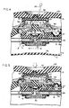
- Figure 5 is a fragmentary sectional view similar to Figure 4 but illustrating the condition of the device during a pumping step.
- Figure 6 is a similar fragmentary sectional view showing the parts during a recovery step in which the pump cavity is being refilled.
- Figure 7 is a transverse sectional view taken along line 7-7 of Figure 3.
- Figure 8 is an exploded sectional view illustrating the deformable septum and associated parts prior to assembly.
- Figure 9 is a sectional view illustrating the parts of Figure 8 in partially assembled condition.
- Figure 10 is an enlarged perspective view illustrating the outlet valve member of the device.
- Figure 11 is an enlarged sectional view showing the relationship of the deformable valve member and deformable valve seat under equalized pressure conditions.
- Figure 12 is a sectional view similar to Figure 11 but showing deformation of the parts in the early stages of a fluid-delivery operation.
- Figure 13 is a sectional view similar to Figures 11 and 12 but showing the parts immediately following breakway of the valve member from its valve seat.
- Referring to the drawings, and particularly to Figures 1-3, the
numeral 10 generally designates an implantable delivery device having a casing 11 formed of soft, deformable polymeric material. While various materials having such properties might be used, an elastomeric material such as silicone rubber has been found particularly effective because of its deformability, recoverability, durability, and biocompatability. Viewed generally, the casing includes preformed (molded) upper andlower walls horizontal midline 14. To facilitate manufacture, theupper wall 12 may be formed in two or more sections that allow the prefabrication of subassemblies. Thus, in the illustration given,upper wall 12 includesmain section 12a,central section 12b, andinner section 12c. The central and inner sections together define anupper chamber 15, whereas the bottom wall defines alower chamber 16. The two chambers communicate and together define an enlargedreservoir 17. - A relatively
rigid support plate 18 is interposed between the upper and lower chambers of the reservoir and, as shown most clearly in Figures 3 and 7, extends substantially the full width and length of the casing. The plate is sandwiched between the upper andlower walls outer layer 18a of silicone rubber or other suitable material to enhance biocompatability and facilitate adhesive attachment of the parts. Thecore 18b of the support plate may be formed of any tough and rigid material, including metallic and ceramic materials, although a polymeric material such as polycarbonate is believed particularly suitable. Opening 19 through thesupport plate 15 places the upper andlower chambers - The pumping means for the device is located in the
upper chamber 15 of the reservoir and is supported uponplate 18. The pumping means includes a dome-shaped pump housing 20 formed of silicone rubber or other suitable elastomeric material. Therim 21 of the pump housing is secured within anannular channel 22 provided in the upper surface ofinner wall section 12c, and a downwardly-projectingstem portion 23 of that wall section projects through an opening 24 in the rigid support plate.Inlet flow passage 25 extends through thestem portion 23 and places the pump chamber orcavity 26 in communication with thelower chamber 16 of the reservoir. Anannular valve seat 27 is provided at the upper end ofpassage 25 and is normally engaged by a dish-shaped elastomericmembrane valve member 28 that has its circular outer peripheral portion secured towall section 12c. Like other components of the drug delivery device, themembrane valve member 27 may be formed of silicone rubber. As shown most clearly in Figures 4-6, the valve member is provided with openings 29 therethrough that are located outboard ofvalve seat 27 and that therefore allow flow of fluid betweenpassage 25 and pumpchamber 26 only when thevalve member 28 is urged away fromvalve seat 27. - Directly below the pump, and mounted along the underside of the
support plate 15, is a rigid filter member ordisc 30. The disc may be formed of sintered metal or a fine metallic mesh and is secured in place by anannular rim 31 adhesively bonded to the underside of thesupport plate 18 about the entrance toinlet passage 25. Directly below thefilter disc 30, the surface of the bottom wall of the casing is provided with parallel ribs13a that prevent the bottom wall from blocking fluid flow fromlower chamber 16 intofilter 30 andinlet passage 25 should the bottom wall be flexed upwardly into contact with the filter (Figure 7). - A
second passage 32 also communicates with thechamber 26 of the pump and leads radially away from the pump through theinner section 12c of the top wall. Thesecond passage 32 is parallel and in close proximity torigid support plate 18 and communicates at its opposite end with avalve opening 33 defined by an annularflexible lip 34 that is preferably formed integrally withsection 12c of the top wall. The lip defines a valve seat and theopening 33 is normally closed by a cup-shapedelastomeric valve member 35 mounted withincylindrical chamber 36. In its normal undeformed state,valve member 35 engageslip 34 to maintain the valve in closed condition; however, as shown in Figure 5, the valve member is capable of being deformed upwardly into unseated condition to allow fluid flow fromsecondary passage 32 andopening 33 intochamber 36 and then intooutlet passage 37. The outlet passage leads tooutlet port 35 which in turn communicates with the lumen of acatheter 39. A tapered ferrule orconnector 40 is secured to the casing 11 and supports the catheter at its point of exit from the casing. - All of the elements so far described, except for
filter disc 30 and the core 18b ofsupport plate 18, are composed of soft, deformable material. Silicone rubber of the same formulation or different formulations may be used for all of such resilient elements which, as already indicated, are secured together by any suitable adhesive to provide the assembly illustrated in the drawings. - The dome-shaped
pump housing 20 has anupstanding stem portion 41 that is anchored to arigid disc 43 formed of polycarbonate or any other suitable material having sufficient strength, hardness, and rigidity to resist needle penetration. In the illustration given, thedisc 43 is formed in twosections pump housing 20; however, it is to be understood that if desired therigid disc 43 may instead be formed in one piece. - The
disc 43 is surrounded by anannular plate 44 that is also formed of rigid material, preferably the same material asdisc 43. The periphery of the annular plate is locked in place between thecentral section 12b and theinner section 12c ofupper wall 12. As shown in Figures 3 and 4, the opposing edges or side surfaces of thedisc 43 andannular plate 44 are spaced apart to provideflow passages 45 that maintain the portions of the upper chamber above and below the disc and annular plate in pressure-equalizing flow relation. Arim 46 of thedisc 43 projects outwardly and is engagable with theannular plate 44 to limit the extent of upward movement of the disc and, if desired, the rim may be serrated or discontinuous to insure thatpassages 45 remain open at all times. - Above
disc 43 is an inverted cup-shapedseptum 47 having anapertured side wall 45 and, when fully assembled, aplanar end wall 49. The lower periphery of theside wall 48 is secured within an annular channel provided inrigid disc 43. The septum is formed of an elastomer such as silicone rubber and is secured to the underside of thecentral section 12b of the casing'stop wall 12 by means of anadhesive attachment layer 50. - Of particular importance is the fact that
end wall 49 of the elastomeric septum is spaced well abovedisc 43 to define a medicament-receivingchamber 51. Also, while shown in the assembly drawings to be of generally planar configuration (except for locating protuberance 52), the end wall in an untensioned state is dome shaped. As shown in Figure 8, in the absence of distorting forces theconvex end wall 49 curves upwardly and inwardly so that when flattened and adhesively secured to the planar undersurface of the casing'stop wall section 12b, theend wall 49 will have its upper surface portion in a compressed state and will be maintained in that compressed state by adhesive layer orpad 50. It has been found that such limited compression of the upper stratum ofend wall 49 greatly enhances the self-sealing properties of the septum upon withdrawal of an injection needle. - Ideally, the upper surface of the
central section 12b of casing'stop wall 12 is provided with anindentation 54 of circular outline. The indentation identifies the target site for both pump actuation and fluid injection and helps a user locate such site by touch even when the fluid delivery device is implanted. When fluid is to be supplied to the reservoir, the needle 55 of a syringe is simply inserted into the casing through the indented zone of the top wall until the tip of the needle engagesrigid disc 43 within medicament-receiving chamber 51 (Figure 4). Discharge of fluid from the syringe flows outwardly throughopenings 56 in the side wall ofseptum 47. Since the upper and lower chambers of the reservoir are in communication, such fluid enters the space above the dome-shapedpump housing 20 and aboveoutlet valve member 35, and is free to pass into the lower chamber throughopening 19. Upon removal of needle 55, thecompressed end wall 49 of theseptum 47 then closes and reseals the reservoir. - The same target zone, as defined by
indentation 54, is used for finger actuation of the pump mechanism. Depression of thetop wall 12 in the area ofindentation 54, as depicted in Figure 5, drives theseptum 47 andrigid disc 43 downwardly, deformingpump housing 20 and substantiallyexhausting pump cavity 26. Fluid in the pump cavity is driven outwardly intosecond passage 32 with the pressure increase beneathoutlet valve 35 causing the outlet valve to flex upwardly into open position. An aliquot of fluid substantially equal to the volume of pump chamber or cavity 26 (when the pump housing is undeformed) is therefore discharged into theoutlet passage 37 and through outlet port 38. When finger pressure is removed, the top wall returns to its original position largely because of the recovery forces exerted by the dome-shapedpump housing 20 and the flexibletop wall portion 12b. As thepump cavity 26 expands, the pressure differential causes themembrane valve member 28 to lift away from itsseat 27, allowing fluid from thelower chamber 16 of the reservoir to enter thepump cavity 26 through thefirst passage 25 and openings 29 in the membrane (Figure 6). Once the pump cavity is filled and pressure is equalized, theinlet valve member 28 closes and the parts again assume the relationships depicted in Figures 3 and 4. - Since the upper and lower chambers of the reservoir are in open communication at all times, deformations of the resilient casing 11 produced by body movement or other causes do not result in unintentional delivery of medicament to the patient. For example, should patient movement cause compression of the device and subsequent upward flexure of
bottom wall 13 from the position shown in Figure 4, fluid displaced fromlower chamber 16 is free to enter the upper chamber of the reservoir, including the area directly aboveoutlet valve member 35. The outlet valve will therefore remain closed despite the deformation of the casing because pressure will be equal on both sides ofoutlet valve 35. The double-headed arrows in Figure 4 are intended to indicate the reversibility of movement of fluid throughout the upper and lower chambers of the reservoir that results in pressure equalization. - Referring to Figures 10-13, it will be noted that
outlet valve member 35 is cup shaped with anupper rim 60 and asemi-spherical body 61. At its lower end, the valve member is provided with a truncated stem orbase portion 62 having an outer surface that flares or curves downwardly, thereby deviating from the otherwise semi-cylindrical outer surface contour of the valve member. - When the device is at rest, the valve member assumes the condition depicted in Figure 11. However, at the commencement of a pumping operation when downward force is applied to the target area of the device's
top wall 12, fluid displaced from the pumping chamber orcavity 26 causes upward movement ofbase portion 62 as illustrated in Figure 12. Theannular lip 34 defining the valve seat, being formed of soft, deformable material, also flexes upwardly so that, despite upward displacement ofbase portion 62, sealing engagement between the lip and the outwardly-curved surface of the base portion persists (Figure 12). Sealing engagement between the valve member and lip continues as the valve member deforms upwardly until, finally, as a result of increasing pressure, the dome-shaped valve member "collapses" and sudden breakaway fromlip 34 occurs. Thelip 34 then returns to its planar state and thevalve member 35 continues upwardly into its fully opened state (Figure 13). - Because fluid cannot escape through the outlet valve until finger pressure on the target zone of the casing's top wall has caused the valve member and valve seat to deform beyond the condition depicted in Figure 12, and because the opening of the valve occurs suddenly when the limits of stability of the dome-shaped valve member are exceeded, the sudden breakaway action provides a tactile feedback signal to the user that may be readily detected through finger contact with the patient's skin overlying the target zone of the device. A user may therefore establish through tactile feedback that a metered dose of medicament has been discharged from the device.
- The initial resistance to opening of the outlet valve, until a threshhold limit of deformation is exceeded, also increases security for the patient by preventing or greatly reducing the possibilities of accidental administration of medicament. Substantial force, preferably in the range of 10 to 20 pounds per square inch, must be exerted directly against the target zone, and in the direction of
pump housing 20, before breakaway of the outlet valve occurs. While the parts may be fabricated so that such breakaway occurs at any selected threshhold limit, a breakaway pressure of approximately 15 pounds per square inch is preferred. - While in the foregoing, an embodiment of the invention has been disclosed in considerable detail for purposes of illustration, it will be understood by those skilled in the art that many of these details may be varied without departing from the spirit and scope of the invention.
Claims (7)
1. An implantable patient-activated device for dispensing metered amounts of fluid to such a patient, comprising a casing formed of soft, deformable polymeric material having a top wall and a bottom wall defining a fluid reservoir with an outlet port; pumping means within said casing including a compressible pump housing having a pumping chamber; first passage-providing means defining an inlet passage extending between said reservoir and said chamber; inlet valve means restricting flow through said inlet passage from said chamber to said reservoir; second passage-providing means defining an outlet passage extending between said chamber and said outlet port; outlet valve means along said outlet passage for controlling flow therethrough; said outlet valve means including an annular valve seat of elastomeric material providing a valve opening and a cup-shaped valve member formed of elastomeric material having an outer surface normally sealingly engaging said valve seat; said top wall of said casing having a target zone operatively connected to said pump housing and deformable by finger pressure to compress said pump housing; said valve seat and valve member being deformable together, when said target zone is depressed to compress said pump housing and displace fluid from said chamber, until said seat reaches a limit of deformation and said valve member breaks away from said seat to allow fluid to surge through said outlet passage, said breakaway and surge providing tactile feedback to signal a user applying finger pressure to said target zone that a metered amount of fluid has been discharged from said device.
2. The device of Claim 1 in which said valve member is cup-shaped and has a rim portion and a generally semi-spherical body portion; said valve member having an outer surface directed towards said outlet passage and an inner surface directed towards said reservoir.
3. The device of Claims 1 or 2 in which said body portion of said valve member includes a base having a truncated stem portion; said truncated stem portion having an outer surface sealingly engagable with said deformable annular valve seat.
4. The device of Claim 2 in which said rim portion of said valve member is secured to said top wall within said casing.
5. An outlet valve for an implantable patient-activated fluid delivery device, said outlet valve including a deformable annular valve seat of elastomeric material defining a valve opening; and a cup-shaped valve member formed of elastomeric material; said valve member having a generally semi-spherical body portion with an outer surface normally sealingly engaging said annular deformable valve seat; said valve seat and valve member being deformable together, in response to pressure increases applied to said valve seat and to the outer surface of said valve member, until said seat reaches a limit of deformation and said valve member breaks away from said seat to allow a surge of fluid through said valve opening.
6. The outlet valve of Claim 5 in which said body portion includes a base in the form of a truncated stem portion; said deformable annular valve seat normally engaging the outer surface of said body portion adjacent said truncated stem portion when said outlet valve is closed.
7. The outlet valve of Claim 5 in which said valve seat is defined by an annular lip having generally parallel planar oppositely-facing surfaces when said valve seat is in an undeformed state.
Applications Claiming Priority (2)
| Application Number | Priority Date | Filing Date | Title |
|---|---|---|---|
| US07/195,770 US4898583A (en) | 1988-05-18 | 1988-05-18 | Implantable patient-activated fluid delivery device and outlet valve therefor |
| US195770 | 1988-05-18 |
Publications (2)
| Publication Number | Publication Date |
|---|---|
| EP0342945A2 true EP0342945A2 (en) | 1989-11-23 |
| EP0342945A3 EP0342945A3 (en) | 1990-06-13 |
Family
ID=22722732
Family Applications (1)
| Application Number | Title | Priority Date | Filing Date |
|---|---|---|---|
| EP89304967A Withdrawn EP0342945A3 (en) | 1988-05-18 | 1989-05-17 | Implantable patient-activated fluid delivery device and outlet valve therefor |
Country Status (4)
| Country | Link |
|---|---|
| US (1) | US4898583A (en) |
| EP (1) | EP0342945A3 (en) |
| JP (1) | JPH0219173A (en) |
| CA (1) | CA1327495C (en) |
Cited By (1)
| Publication number | Priority date | Publication date | Assignee | Title |
|---|---|---|---|---|
| US5895372A (en) * | 1994-01-27 | 1999-04-20 | Zenner; Hans Peter | Implantable dosaging system |
Families Citing this family (18)
| Publication number | Priority date | Publication date | Assignee | Title |
|---|---|---|---|---|
| US5728061A (en) * | 1988-10-07 | 1998-03-17 | Ahmed; Abdul Mateen | Device and method for treating hydrocephalus |
| US5085644A (en) * | 1990-04-02 | 1992-02-04 | Pudenz-Schulte Medical Research Corporation | Sterilizable medication infusion device with dose recharge restriction |
| US5152753A (en) * | 1990-04-02 | 1992-10-06 | Pudenz-Schulte Medical Research Corporation | Medication infusion device with dose recharge restriction |
| JPH0613736Y2 (en) * | 1991-05-15 | 1994-04-13 | ダウ コーニング アジア株式会社 | Hydrocephalus shunt device |
| US5257979A (en) * | 1992-07-27 | 1993-11-02 | Ravindar Jagpal | Instrument for catheterization |
| US5342313A (en) * | 1992-11-02 | 1994-08-30 | Infusion Technologies Corporation | Fluid pump for a flexible, variable geometry reservoir |
| US5232439A (en) * | 1992-11-02 | 1993-08-03 | Infusion Technologies Corporation | Method for pumping fluid from a flexible, variable geometry reservoir |
| US5330431A (en) * | 1993-03-12 | 1994-07-19 | Glenn Herskowitz | Infusion pump |
| US5695479A (en) * | 1993-11-01 | 1997-12-09 | Jagpal; Ravindar | Instrument, system, kit and method for catheterization procedures |
| CA2151407A1 (en) * | 1995-06-09 | 1996-12-10 | Duncan Newman | Injection device |
| SE9704769D0 (en) * | 1997-12-19 | 1997-12-19 | Astra Ab | Medical device |
| US6074366A (en) * | 1998-01-16 | 2000-06-13 | Tandem Medical Inc. | Medication delivery apparatus |
| US6193682B1 (en) | 1998-03-16 | 2001-02-27 | Abdul Mateen Ahmed | Low profile neonatal hydrocephalus device and methods |
| US6471675B1 (en) * | 1999-04-30 | 2002-10-29 | Medtronic, Inc. | Passive flow control devices for implantable pumps |
| US6726655B1 (en) | 1999-11-05 | 2004-04-27 | Tandem Medical | Medication delivery system |
| DE102008030942A1 (en) | 2008-07-02 | 2010-01-07 | Christoph Miethke Gmbh & Co Kg | Cerebrospinal fluid drainage |
| WO2012161248A1 (en) | 2011-05-25 | 2012-11-29 | 新日鐵住金株式会社 | Hot-rolled steel sheet and process for producing same |
| US9512508B2 (en) | 2011-07-27 | 2016-12-06 | Nippon Steel and Sumitomo Metal Corporation | High-strength cold-rolled steel sheet having excellent stretch flangeability and precision punchability and manufacturing method thereof |
Citations (5)
| Publication number | Priority date | Publication date | Assignee | Title |
|---|---|---|---|---|
| US3827439A (en) * | 1972-10-30 | 1974-08-06 | Heyer Schulte Corp | Plug valve for physiological shunt systems |
| EP0142866A2 (en) * | 1983-11-22 | 1985-05-29 | Consolidated Controls Corporation | Compact implantable medication infusion unit and method of filling and sealing the pressure stabilizing chamber thereof |
| EP0174757A1 (en) * | 1984-09-04 | 1986-03-19 | BAXTER INTERNATIONAL INC. (a Delaware corporation) | An implantable demand medication delivery assembly |
| EP0177250A2 (en) * | 1984-10-01 | 1986-04-09 | Cook Incorporated | Implantable insulin administration device |
| EP0229729A2 (en) * | 1986-01-17 | 1987-07-22 | Strato/Infusaid Inc. | Implantable treatment reservoir |
Family Cites Families (27)
| Publication number | Priority date | Publication date | Assignee | Title |
|---|---|---|---|---|
| US2638127A (en) * | 1943-09-09 | 1953-05-12 | Clayton Manufacturing Co | Molded diaphragm structure |
| US3769982A (en) * | 1971-09-24 | 1973-11-06 | R Schulte | Physiological drainage system with closure means responsive to downstream suction |
| US3768508A (en) * | 1972-01-24 | 1973-10-30 | R Schulte | Valve for controllable release of entrapped body fluids |
| US3850190A (en) * | 1973-09-17 | 1974-11-26 | Mark Controls Corp | Backflow preventer |
| US4013074A (en) * | 1974-06-21 | 1977-03-22 | Siposs George G | Implantable medication-dispensing device |
| US4193397A (en) * | 1977-12-01 | 1980-03-18 | Metal Bellows Corporation | Infusion apparatus and method |
| US4190040A (en) * | 1978-07-03 | 1980-02-26 | American Hospital Supply Corporation | Resealable puncture housing for surgical implantation |
| US4258711A (en) * | 1979-02-05 | 1981-03-31 | Metal Bellows Corporation | Infusion apparatus and method |
| US4360019A (en) * | 1979-02-28 | 1982-11-23 | Andros Incorporated | Implantable infusion device |
| US4265241A (en) * | 1979-02-28 | 1981-05-05 | Andros Incorporated | Implantable infusion device |
| US4400169A (en) * | 1980-10-27 | 1983-08-23 | University Of Utah Research Foundation | Subcutaneous peritoneal injection catheter |
| DE3138320A1 (en) * | 1981-09-25 | 1983-04-14 | Siemens AG, 1000 Berlin und 8000 München | INFUSION DEVICE PROVIDED FOR IMPLANTATION IN A LIVING BODY |
| US4437457A (en) * | 1982-04-27 | 1984-03-20 | Medical Engineering Corporation | Artificial sphincter with improved pressure control valve |
| US4496343A (en) * | 1982-06-14 | 1985-01-29 | Infusaid Corporation | Infusate pump |
| US4544371A (en) * | 1982-10-05 | 1985-10-01 | American Hospital Supply Corporation | Implantable metered dose drug delivery system |
| US4487603A (en) * | 1982-11-26 | 1984-12-11 | Cordis Corporation | Implantable microinfusion pump system |
| US4557722A (en) * | 1983-04-13 | 1985-12-10 | Cordis Corporation | Fill port for an implantable dispensing system |
| US4548607A (en) * | 1983-04-13 | 1985-10-22 | Cordis Corporation | Implantable manually actuated medication dispensing system |
| US4639244A (en) * | 1983-05-03 | 1987-01-27 | Nabil I. Rizk | Implantable electrophoretic pump for ionic drugs and associated methods |
| US4560375A (en) * | 1983-06-30 | 1985-12-24 | Pudenz-Schulte Medical Research Corp. | Flow control valve |
| US4543088A (en) * | 1983-11-07 | 1985-09-24 | American Hospital Supply Corporation | Self-sealing subcutaneous injection site |
| US4572168A (en) * | 1983-12-20 | 1986-02-25 | Fischell Robert | Fully implantable vapor pressure actuated penile erection device and method |
| US4668231A (en) * | 1984-02-15 | 1987-05-26 | Cordis Corporation | Implantable hand-operable dispensers for fluid medicaments |
| US4588394A (en) * | 1984-03-16 | 1986-05-13 | Pudenz-Schulte Medical Research Corp. | Infusion reservoir and pump system |
| US4627832A (en) * | 1984-05-08 | 1986-12-09 | Cordis Corporation | Three stage intracranial pressure relief valve having single-piece valve stem |
| CA1233363A (en) * | 1984-06-01 | 1988-03-01 | Robert E. Fischell | Single valve diaphragm pump with decreased sensitivity to ambient conditions |
| US4626244A (en) * | 1985-02-01 | 1986-12-02 | Consolidated Controls Corporation | Implantable medication infusion device |
-
1988
- 1988-05-18 US US07/195,770 patent/US4898583A/en not_active Expired - Fee Related
-
1989
- 1989-05-16 CA CA000599750A patent/CA1327495C/en not_active Expired - Fee Related
- 1989-05-17 EP EP89304967A patent/EP0342945A3/en not_active Withdrawn
- 1989-05-18 JP JP1125455A patent/JPH0219173A/en active Pending
Patent Citations (5)
| Publication number | Priority date | Publication date | Assignee | Title |
|---|---|---|---|---|
| US3827439A (en) * | 1972-10-30 | 1974-08-06 | Heyer Schulte Corp | Plug valve for physiological shunt systems |
| EP0142866A2 (en) * | 1983-11-22 | 1985-05-29 | Consolidated Controls Corporation | Compact implantable medication infusion unit and method of filling and sealing the pressure stabilizing chamber thereof |
| EP0174757A1 (en) * | 1984-09-04 | 1986-03-19 | BAXTER INTERNATIONAL INC. (a Delaware corporation) | An implantable demand medication delivery assembly |
| EP0177250A2 (en) * | 1984-10-01 | 1986-04-09 | Cook Incorporated | Implantable insulin administration device |
| EP0229729A2 (en) * | 1986-01-17 | 1987-07-22 | Strato/Infusaid Inc. | Implantable treatment reservoir |
Cited By (1)
| Publication number | Priority date | Publication date | Assignee | Title |
|---|---|---|---|---|
| US5895372A (en) * | 1994-01-27 | 1999-04-20 | Zenner; Hans Peter | Implantable dosaging system |
Also Published As
| Publication number | Publication date |
|---|---|
| EP0342945A3 (en) | 1990-06-13 |
| JPH0219173A (en) | 1990-01-23 |
| US4898583A (en) | 1990-02-06 |
| CA1327495C (en) | 1994-03-08 |
Similar Documents
| Publication | Publication Date | Title |
|---|---|---|
| US4898585A (en) | Implantable patient-activated fluid delivery device with bolus injection port | |
| US4898584A (en) | Implantable patient-activated fluid delivery device | |
| US4898583A (en) | Implantable patient-activated fluid delivery device and outlet valve therefor | |
| US4548607A (en) | Implantable manually actuated medication dispensing system | |
| US8425493B2 (en) | Implantable medication delivery device | |
| EP0998317B1 (en) | Inlet port for a medication infusion pump | |
| US5053031A (en) | Pump infusion system | |
| US4634427A (en) | Implantable demand medication delivery assembly | |
| EP1464351B1 (en) | Low-profile automatic injection device with self-emptying reservoir | |
| US4544371A (en) | Implantable metered dose drug delivery system | |
| US4668231A (en) | Implantable hand-operable dispensers for fluid medicaments | |
| US5895372A (en) | Implantable dosaging system | |
| EP0291612B1 (en) | Implantable pump. | |
| US20120078197A1 (en) | Portable infusion pump with anti-siphoning protection | |
| JPH09285539A (en) | Medicine self-injecting device | |
| US20130085470A1 (en) | Method for pressure-independent, refillable drug infusion device | |
| CA1333144C (en) | Implantable drug delivery system | |
| EP0258777A1 (en) | Implantable dispenser for a liquid substance | |
| JP3147346B2 (en) | Chemical self-injection tool | |
| WO2005089836A2 (en) | Apparatus and method for dispensing a liquid | |
| CA1245930A (en) | Body mounted pump housing and pump assembly employing the same | |
| CA1231282A (en) | Pumping means for programmable infusion system |
Legal Events
| Date | Code | Title | Description |
|---|---|---|---|
| PUAI | Public reference made under article 153(3) epc to a published international application that has entered the european phase |
Free format text: ORIGINAL CODE: 0009012 |
|
| AK | Designated contracting states |
Kind code of ref document: A2 Designated state(s): DE FR GB |
|
| PUAL | Search report despatched |
Free format text: ORIGINAL CODE: 0009013 |
|
| RHK1 | Main classification (correction) |
Ipc: A61M 5/142 |
|
| RHK1 | Main classification (correction) |
Ipc: A61M 5/14 |
|
| AK | Designated contracting states |
Kind code of ref document: A3 Designated state(s): DE FR GB |
|
| STAA | Information on the status of an ep patent application or granted ep patent |
Free format text: STATUS: THE APPLICATION IS DEEMED TO BE WITHDRAWN |
|
| 18D | Application deemed to be withdrawn |
Effective date: 19901214 |