EP0342419A1 - Verfahren zur Beobachtung einer Szene und Einrichtung zur Durchführung des Verfahrens - Google Patents
Verfahren zur Beobachtung einer Szene und Einrichtung zur Durchführung des Verfahrens Download PDFInfo
- Publication number
- EP0342419A1 EP0342419A1 EP89107815A EP89107815A EP0342419A1 EP 0342419 A1 EP0342419 A1 EP 0342419A1 EP 89107815 A EP89107815 A EP 89107815A EP 89107815 A EP89107815 A EP 89107815A EP 0342419 A1 EP0342419 A1 EP 0342419A1
- Authority
- EP
- European Patent Office
- Prior art keywords
- image
- channel
- nfov
- scene
- view
- Prior art date
- Legal status (The legal status is an assumption and is not a legal conclusion. Google has not performed a legal analysis and makes no representation as to the accuracy of the status listed.)
- Granted
Links
Images


Classifications
-
- H—ELECTRICITY
- H04—ELECTRIC COMMUNICATION TECHNIQUE
- H04N—PICTORIAL COMMUNICATION, e.g. TELEVISION
- H04N5/00—Details of television systems
- H04N5/30—Transforming light or analogous information into electric information
- H04N5/33—Transforming infrared radiation
Definitions
- the invention relates to a method for observing a scene with an infrared imaging system with two optical channels of different fields of view on the image acquisition side and a representation of the scene captured by the channel with the large field of view and the scene captured by the channel with the small field of view on the image display side , and a device for carrying out the method.
- thermal imaging devices are often used to observe a scene. Devices of this type can also be used at night and enable location and observation of heat-radiating objects and, in conjunction with suitable display devices, also flight guidance and navigation at night.
- suitable display devices also flight guidance and navigation at night.
- the observer is simultaneously offered an image of the overall scene and a detail image on a number of monitors corresponding to the number of recording systems, for example on at least two monitors, the detail displayed on the second monitor being able to be recognized by means of the frame displayed on the second monitor and where the detail image of the first monitor is in the overall scene.
- the superimposed frame is adjusted from the relative movement of the two recording systems which can be pivoted relative to one another.
- this known method requires at least two monitors on the image display side, so that in the case of a one-man observation, the observer must pay attention to two monitors at the same time when looking at a larger area and when observing and recognizing details within the overall scene or always have to "switch" his line of sight from one monitor to the other monitor. Such a method is therefore less suitable for one-man observation.
- the transmission properties of the device chain down to the eye only allow limited detail recognition at a limited distance.
- the invention is therefore based on the object of simplifying a method of the type mentioned at the beginning for a one-man observation and at the same time improving the detail recognition at a greater distance without losing the necessary 1: 1 representation of the entire scene.
- IR image signals of both channels are first of all using two conversion devices converted into TV video signals and synchronized with one another using a first synchronizing device and then fed to an image mixing device such that a part of the TV video signal of the NFOV channel is selected by a section selector and is superimposed on the TV video signals of the WFOV channel in the image mixing device, and that this mixed video signal is then made visible by means of a single image display device in such a way that an overview scene of the large field of view and a superimposed image section of the small field of view appear simultaneously in the image shown.
- the invention thus sees simultaneous observation with two optical channels of different fields of view and thus different magnifications, a fade-in of an image section from the small field of view, i.e. from the enlargement channel, into the image of the overall scene and thus into the 1: 1 display and a simultaneous display using a single image display device.
- This specifies a method which is advantageous for a one-man observation and which offers the single observer both a 1: 1 representation of the entire scene and a detailed image on a single image display device, so that the sole observer when viewing a larger area and with the observation and recognition of details only has to focus on one image. Observation in the case of a one-man observation is thus considerably simplified and is therefore particularly well suited for flight guidance.
- the method according to the invention is particularly advantageous for use in sighting and targeting processes if the process shown Image section of the NFOV channel is tracked by a tracker using a tracker to track a relative movement of an object in the small field of view.
- the selected object is thus continuously shown to the observer in full.
- the tracking of the image section enables the observer to track the optical axis of the WFOV channel to the object without losing sight of it.
- a device for performing the method is characterized in claims 9 to 18.
- the infrared imaging system consists of a two-channel camera which is designed with two optical systems of different magnifications and with a common scanning system.
- the infrared imaging system consists of a two-channel camera which is designed with two optical systems of different magnifications and with a common scanning system.
- two discrete, mutually synchronized individual cameras instead of a two-channel camera, but this makes the system more expensive.
- the image display device on the image display side expediently consists of a display device with a single screen.
- the image display device consists of a helmet viewing device.
- the aiming platform provided for the infrared imaging system can be aligned in azimuth and elevation by means of a helmet visor of the observer, ie when the observer's head is rotated, the infrared imaging system also pivots so that it looks in the same direction as the observer.
- the device according to FIG. 1 has an infrared image system FLIR (Forward Looking InfraRed) on the image recording side, which preferably consists of a two-channel camera Dual FOV FLIR, which is stabilized in two axes, not shown here, in azimuth and elevation swiveling straightening platform is mounted.
- the infrared imaging system FLIR has two optical channels with different fields of view WFOV (Wide Field Of View) and NFOV (Narrow Field Of View).
- the dual-channel camera Dual FOV FLIR is designed with two optical systems of different magnifications, the large field of view WFOV, for example, comprising 30 x 40 o (vertical x horizontal), while the small field of view NFOV then, for example, approximately 3 x 4 o (vertical x horizontal).
- a 1: 1 representation of a scene is thus generated via the WFOV channel, while the NFOV channel gives a 10-fold magnification for the values mentioned.
- the optical axis of the NFOV channel lies within the angular range of the large field of view WFOV, preferably the optical axes of the NFOV channel and the WFOV channel are aligned parallel to one another.
- the dual-channel Dual FOV FLIR camera is also designed with a common scanning system.
- An operator for example the observer himself, now uses a control panel CP and a section selector SS to insert a part of the TV video signal of the NFOV channel that contains, for example, only a specific target object, that is to say only an image section of the NFOV channel of, for example, 1 ⁇ 1 , 5 o at the values mentioned, superimposed on the TV video signal of the WFOV channel.
- This mixed video signal is then made visible on the image display side in such a way that an overview scene of the large field of view WFOV and a faded-in image section of the small field of view NFOV appear in the image shown, the size and position of the part to be faded in, ie the faded-in part Scene details, controlled by a signal generated in the section selector SS.
- a single image display device D is provided, which consists, for example, of a display device with a single screen MON.
- the image display device can also consist of a field of vision viewer HUD or a helmet viewer HMD / HMS, in the latter case the aiming platform of the infrared image system FLIR can be aligned in azimuth and elevation through the helmet visor of the observer.
- the mixed video signal in a symbol generator SYG is symbolized to identify the position of the displayed image section in the large field of view WFOV and / or suitable additional symbol signals, e.g. to display operating states, reference axes, distance, height or to identify scene details.
- a second synchronization device SYD2 is also provided, with the aid of which the part of the TV video signal of the NFOV channel selected by the section selector SS can be moved electronically is and can be faded into the TV video signal of the WFOV channel so that the image section to be displayed of the NFOV channel appears in a preselected area of the image display device D.
- the device also contains a tracker T for tracking a striking scene detail of the NFOV channel.
- the tracker is switched to a scene detail by aligning the infrared image system FLIR with the symbols shown to the desired detail.
- the tracker is activated and at the same time the section selector SS is switched from the image mixing device PMD to the tracker T.
- the track signals generated by the tracker control the size and position of the displayed image section.
- the image section follows the detail on the MON screen of the image display device D within the possible display area of the NFOV channel, ie the image section moves on the MON screen.
- the second synchronization device SYD2 By activating the second synchronization device SYD2 from the control panel CP via the detail selector SS, it is possible to have the tracked scene detail appear in a fixed position on the screen in the displayed image detail. This is done in such a way that signals are generated in the control panel CP which decouple the tracker T from the section selector SS and couple the synchronization device SYD2 to the tracker.
- the detail selector SS controls the image detail to be faded in according to pre-programmed values.
- the tracker now controls, via the second synchronization device SYD2, the synchronization signals supplied by the first synchronization device SYD1 to the conversion device C2 such that the tracked scene detail appears in the stationary image section on the image display device D.
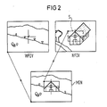
- FIGS. 2 and 3 Exemplary representations of the mixed video signal on the image representation side are shown in FIGS. 2 and 3.
- Fig. 2 the scene captured by the WFOV channel and the scene captured by the NFOV channel are shown, as well as a mixed image, in which a by e.g. Rectangular symbolism S marked image section of the NFOV channel is faded into the picture of the WFOV channel so that the location of the faded-in image section in the mixed image shown on the MON screen corresponds to its relative position in the small field of view NFOV.
- a by e.g. Rectangular symbolism S marked image section of the NFOV channel is faded into the picture of the WFOV channel so that the location of the faded-in image section in the mixed image shown on the MON screen corresponds to its relative position in the small field of view NFOV.
- FIG. 3 Another type of representation, in particular provided in the operating mode “tracking”, is shown in FIG. 3.
- the image section of the NFOV channel again identified by a symbol S, is faded into the image of the WFOV channel in such a way that the location of the faded-in image section is shown the mixed image shown on the screen is located approximately in the upper right quadrant, so that a specific object can be seen as a detail both in the 1: 1 representation of the WFOV channel in the overview scene and in the enlarged image section of the NFOV channel.
Landscapes
- Engineering & Computer Science (AREA)
- Multimedia (AREA)
- Signal Processing (AREA)
- Closed-Circuit Television Systems (AREA)
Abstract
Description
- Die Erfindung betrifft ein Verfahren zur Beobachtung einer Szene mit einem Infrarot-Bildsystem mit zwei optischen Kanälen unterschiedlicher Sehfelder auf der Bildaufnahmeseite und einer Darstellung der durch den Kanal mit dem großen Sehfeld erfaßten Szene sowie der durch den Kanal mit dem kleinen Sehfeld erfaßten Szene auf der Bilddarstellungsseite, und eine Einrichtung zur Durchführung des Verfahrens.
- Zur Beobachtung einer Szene werden heutzutage häufig Wärmebildgeräte verwendet. Derartige Geräte können auch nachts eingesetzt werden und ermöglichen eine Ortung und Beobachtung von wärmestrahlenden Objekten sowie in Verbindung mit geeigneten Darstellungseinrichtungen auch eine Flugführung und Navigation bei Nacht. Bei der Beobachtung eines größeren Bereiches im allgemeinen wie auch zur Flugführung und Navigation bei Nacht im besonderen ist es erwünscht, sowohl die gesamte Szene überblicken als auch Details innerhalb der Gesamtszene erkennen zu können. Es ist daher zweckmäßig, die Szene mit zwei Wärmebildgeräten unterschiedlicher Vergrößerung zu beobachten, dabei mittels des ersten Wärmebildgerätes die Szene zu erfassen und in 1:1 -Darstellung wiederzugeben, das zweite Wärmebildgerät auf ein zu erkennendes Objekt zu richten und dann auf die vergrößerte Darstellung umzuschalten. Derartige Verfahren haben jedoch den Nachteil, daß dem Beobachter entweder nur das Bild der Gesamtszene oder nur ein Detailbild zur Verfügung steht. Ein Verfahren, bei welchem dem Beobachter sowohl das Bild der gesamten Szene als auch ein Detailbild geboten wird, ist aus der DE-PS 31 46 552 bekannt. Dieses Verfahren sieht zumindest zwei Aufnahmesysteme für Bilder unterschiedlicher Abbildungsmaßstäbe und eine entsprechende Anzahl von den jeweiligen Aufnahmesystemen zugeordneten Monitoren vor, wobei in das Schirmbild z.B. eines zweiten Monitors ein Rahmen eingeblendet wird, dessen umschlossener Bildausschnitt dem Gesamtbild eines ersten Monitors entspricht, un wobei der variable Rahmen nach Höhe und Seite automatisch der Relativbewegung der Aufnahmesysteme nachgeführt wird. Damit wird dem Beobachter auf einer der Anzahl der Aufnahmesysteme entsprechenden Anzahl von Monitoren, also z.B. auf mindestens zwei Monitoren, gleichzeitig ein Bild der Gesamtszene und ein Detailbild geboten, wobei mittels des eingeblendeten Rahmens auf dem zweiten Monitor erkennbar ist, welches Detail das erste Aufnahmesystem gerade erfaßt und wo das Detailbild des ersten Monitors in der Gesamtszene liegt. Der eingeblendete Rahmen wird aus der Relativbewegung der beiden gegeneinander schwenkbaren Aufnahmesysteme zueinander verstellt. Dieses bekannte Verfahren erfordert aber auf der Bilddarstellungsseite mindestens zwei Monitore, so daß im Falle einer Ein-Mann-Beobachtung der Beobachter bei der Betrachtung eines größeren Bereiches und bei der Beobachtung und Erkennung von Details innerhalb der Gesamtszene sein Augenmerk gleichzeitig auf zwei Monitore zu richten hat bzw. seine Blickrichtung immer von einem Monitor zum anderen Monitor "umschalten" muß. Ein derartiges Verfahren ist daher für eine Ein-Mann-Beobachtung weniger gut geeignet. Außerdem ermöglichen die Übertragungseigenschaften der Gerätekette bis hin zum Auge nur eine begrenzte Detailerkennung in eingeschränkter Entfernung.
- Der Erfindung liegt daher die Aufgabe zugrunde, ein Verfahren der eingangs genannten Art und Weise für eine Ein-Mann-Beobachtung zu vereinfachen und dabei die Detailerkennbarkeit bei höherer Entfernung zu verbessern, ohne die notwendige 1:1-Darstellung der Gesamtszene zu verlieren.
- Diese Aufgabe wird bei einem Verfahren der eingangs genannten Art gemäß der Erfindung dadurch gelöst, daß die IR-Bildsignale beider Kanäle zunächst mit Hilfe von zwei Umwandlungseinrichtungen in TV-Videosignale umgewandelt und mit einer ersten Synchronisiereinrichtung aufeinander synchronisiert und dann einer Bildmischeinrichtung zugeführt werden, daß ein Teil des TV-Videosignals des NFOV-Kanales von einem Ausschnittselektor ausgewählt und in der Bildmischeinrichtung in das TV-Videosignale des WFOV-Kanales eingeblendet wird, und daß anschließend dieses Misch-Videosignal mittels einer einzigen Bilddarstellungseinrichtung in der Weise sichtbar gemacht wird, daß in dem dargestellten Bild gleichzeitig eine Übersichtsszene des großen Sehfeldes und ein eingeblendeter Bildausschnitt des kleinen Sehfeldes erscheint.
- Die Erfindung sieht also eine gleichzeitige Beobachtung mit zwei optischen Kanälen unterschiedlicher Sehfelder und damit unterschiedlicher Vergrößerung, eine Einblendung eines Bildausschnittes aus dem kleinen Sehfeld, d.h. aus dem Vergrößerungskanal, in das Bild der Gesamtszene und damit in die 1:1-Darstellung sowie eine gleichzeitige Darstellung mittels einer einzigen Bilddarstellungseinrichtung vor. Damit ist ein für eine Ein-Mann-Beobachtung vorteilhaftes Verfahren angegeben, das dem einzigen Beobachter auf einer einzigen Bilddarstellungseinrichtung sowohl eine 1:1-Darstellung der Gesamtszene als auch ein Detailbild bietet, so daß der einzige Beobachter bei der Betrachtung eines größeren Bereiches und bei der Beobachtung und Erkennung von Details sein Augenmerk nur auf eine einzige Bilddarstellung richten muß. Damit ist die Beobachtung im Falle einer Ein-Mann-Beobachtung erheblich vereinfacht und daher insbesondere zur Flugführung besonders gut geeignet. Außerdem wird dadurch, daß nur ein z.B. ein bestimmtes Zielobjekt enthaltender Bildausschnitt des Vergrößerungskanales in das Bild der Gesamtszene eingeblendet wird, eine höhere Detailerkennbarkeit bei höherer Entfernung ermöglicht, ohne daß die notwendige Orientierungshilfe der 1:1-Darstellung der Gesamtszene aus dem "Navigationskanal" verloren geht.
- Besonders vorteilhaft ist das erfindungsgemäße Verfahren bei Visier- und Zielvorgängen einzusetzen, wenn der dargestellte Bildausschnitt des NFOV-Kanales durch einen Trackvorgang mittels eines Trackers einer Relativbewegung eines Objektes im kleinen Sehfeld nachgeführt wird. Dem Beobachter wird somit kontinuierlich das ausgewählte Objekt voll dargestellt. Außerdem ist der Beobachter durch die Nachführung des Bildausschnittes in der Lage, die optische Achse des WFOV-Kanales dem Objekt nachzuführen, ohne es aus dem Blickfeld zu verlieren.
- Weitere Verfahrensschritte sind in den Ansprüchen 2 bis 4 und 6 bis 8 angegeben.
- Eine Einrichtung zur Durchführung des Verfahrens ist in den Ansprüchen 9 bis 18 gekennzeichnet.
- Um den Aufwand für das Infrarot-Bildsystem auf der Bildaufnahmeseite möglichst niedrig zu halten, ist es vorteilhaft, wenn das Infrarot-Bildsystem aus einer Zwei-Kanal-Kamera besteht, die mit zwei optischen Systemen unterschiedlicher Vergrößerung und mit einem gemeinsamen Scansystem ausgebildet ist. Es ist aber auch möglich, anstelle einer Zwei-Kanal-Kamera zwei diskrete, aufeinander synchronisierte Einzelkameras zu verwenden, was jedoch das System verteuert.
- Zweckmäßigerweise besteht auf der Bilddarstellungsseite die Bilddarstellungseinrichtung aus einem Sichtgerät mit einem einzigen Bildschirm. Besonders vorteilhaft ist es jedoch, wenn die Bilddarstellungseinrichtung aus einem Helmsichtgerät besteht. In diesem Fall ist die für das Infrarot-Bildsystem vorgesehene Richtplattform in Azimut und Elevation durch ein Helmvisier des Beobachters ausrichtbar, d.h. bei einer Drehung des Kopfes des Beobachters schwenkt das Infrarot-Bildsystem mit, so daß es in dieselbe Richtung blickt wie der Beobachter. Es ist aber auch möglich, die Richtplattform des Infrarot-Bildsystems mittels einer übergeordneten Steuereinrichtung auszurichten.
- Das erfindungsgemäße Verfahren wird im folgenden anhand einer in der Zeichnung schematisch in der Art eines Blockschaltbildes aufgezeigten Ausführungsform einer Einrichtung zur Durchführung des Verfahrens näher beschrieben.
- Die Einrichtung nach Fig. 1 besitzt auf der Bildaufnahmeseite ein Infrarot-Bildsystem FLIR (Forward Looking InfraRed), das vorzugsweise aus einer Zwei-Kanal-Kamera Dual FOV FLIR besteht, die auf einer hier nicht näher dargestellten, zweiachsig stabilisierten, in Azimut und Elevation schwenkbaren Richtplattform montiert ist. Das Infrarot-Bildsystem FLIR weist zwei optische Kanäle unterschiedlicher Sehfelder WFOV (Wide Field Of View) und NFOV (Narrow Field Of View) auf. Dementsprechend ist die Zwei-Kanal-Kamera Dual FOV FLIR mit zwei optischen Systemen unterschiedlicher Vergrößerung ausgebildet, wobei das große Sehfeld WFOV z.B. 30 x 40o umfaßt (vertikal x horizontal), während das kleine Sehfeld NFOV dann z.B. etwa 3 x 4o (vertikal x horizontal) hat. Über den WFOV-Kanal wird also eine 1 : 1 -Darstellung einer Szene erzeugt, während über den NFOV-Kanal bei den genannten Werten eine 10-fache Vergrößerung gegeben ist. Die optische Achse des NFOV-Kanales liegt innerhalb des Winkelbereiches des großen Sehfeldes WFOV, vorzugsweise sind die optischen Achsen des NFOV-Kanales und des WFOV-Kanales parallel zueinander ausgerichtet. Die Zwei-Kanal-Kamera Dual FOV FLIR ist ferner noch mit einem gemeinsamen Scansystem ausgebildet.
- Mit dem Infrarot-Bildsystem FLIR bzw. der Zwei-Kanal-Kamera Dual FOV FLIR wird eine Szene nun gleichzeitig mit beiden Kanälen des Systems beobachtet. Am Ausgang des Infrarot-Bildsystems FLIR steht die volle Bildinformation beider Sehfelder simultan zur Verfügung. Diese vom Infrarot-Bildsystem generierten IR-Bildsignale werden zunächst mit Hilfe von zwei Umwandlungseinrichtungen C1 und C2 in TV-Videosignale umgewandelt. Mit Hilfe von Steuersignalen, die in einer ersten Synchronisiereinrichtung SYD1 erzeugt werden, werden die TV-Videosignale aufeinander synchronisiert, d.h. fernsehgerecht aufbereitet und dann einer Bildmischeinrichtung PMD zugeführt. Von einem Operator, z.B. vom Beobachter selbst, wird nun über ein Bedienfeld CP und einen Ausschnittselektor SS ein z.B. nur ein bestimmtes Zielobjekt enthaltender Teil des TV-Videosignals des NFOV-Kanals, also lediglich ein Bildausschnitt des NFOV-Kanals, von z.B. 1 x 1,5o bei den genannten Werten, in das TV-Videosignal des WFOV-Kanals eingeblendet. Anschließend wird dieses Misch-Videosignal auf der Bilddarstellungsseite in der Weise sichtbar gemacht, daß in dem dargestellten Bild gleichzeitig eine Übersichtsszene des großen Sehfeldes WFOV und ein eingeblendeter Bildausschnitt des kleinen Sehfeldes NFOV erscheint, wobei die Größe und die Lage des einzublendenden Teiles, d.h. des einzublendenden Szenendetails, durch ein im Ausschnittselektor SS generiertes Signal gesteuert wird. Zur Sichtbarmachung des Misch-Videosignals auf der Bilddarstellungsseite ist eine einzige Bilddarstellungseinrichtung D vorgesehen, die z.B. aus einem Sichtgerät mit einem einzigen Bildschirm MON besteht. Die Bilddarstellungseinrichtung kann aber auch aus einem Blickfeldsichtgerät HUD oder einem Helmsichtgerät HMD/HMS bestehen, wobei im letzteren Fall die Richtplattform des Infrarot-Bildsystems FLIR in Azimut und Elevation durch das Helmvisier des Beobachters ausrichtbar ist.
- Auf dem Weg von der Bildmischeinrichtung PMD zur Bilddarstellungseinrichtung D werden dem Misch-Videosignal in einem Symbolgenerator SYG eine Symbolik zur Kennzeichnung der Lage des dargestellten Bildausschnittes im großen Sehfeld WFOV und/oder geeignete zusätzliche Symbolsignale, z.B. zur Darstellung von Betriebszuständen, Referenzachsen, Entfernung, Höhe oder zur Kennzeichnung von Szenendetails, überlagert.
- Ferner ist neben der ersten Synchronisiereinrichtung SYD1 noch eine zweite Synchronisiereinrichtung SYD2 vorgesehen, mit deren Hilfe der vom Ausschnittselektor SS ausgewählte Teil des TV-Videosignals des NFOV-Kanals elektronisch verschiebbar ist und so in das TV-Videosignal des WFOV-Kanales eingeblendet werden kann, daß der darzustellende Bildausschnitt des NFOV-Kanales in einem vorgewählten Bereich der Bilddarstellungseinrichtung D erscheint.
- Die Einrichtung enthält weiterhin einen Tracker T zum Tracken eines markanten Szenendetails des NFOV-Kanales. Die Aufschaltung des Trackers auf ein Szenendetail erfolgt durch Ausrichtung des Infrarot-Bildsystems FLIR mittels der eingeblendeten Symbole auf das gewünschte Detail. Durch Einschalten der Betriebsart "Tracken" am Bedienfeld CP wird der Tracker aktiviert und gleichzeitig der Ausschnittselektor SS von der Bildmischeinrichtung PMD auf den Tracker T umgeschaltet. Von nun an steuern die vom Tracker erzeugten Tracksignale die Größe und Lage des eingeblendeten Bildausschnittes. Bei einer Relativbewegung des getrackten Details zur Visierlinie des NFOV-Kanales folgt der Bildausschnitt dem Detail auf dem Bildschirm MON der Bilddarstellungseinrichtung D innerhalb des möglichen Darstellungsbereiches des NFOV-Kanales, d.h. der Bildausschnitt wandert auf dem Bildschirm MON. Durch Aktivierung der zweiten Synchronisiereinrichtung SYD2 vom Bedienfeld CP aus über den Ausschnittselektor SS ist es möglich, das getrackte Szenendetail im eingeblendeten Bildausschnitt in fester Position auf dem Bildschirm erscheinen zu lassen. Dies geschieht in der Weise, daß im Bedienfeld CP Signale erzeugt werden, die den Tracker T vom Ausschnittselektor SS entkoppeln und die Synchronisiereinrichtung SYD2 an den Tracker ankoppeln. Der Ausschnittselektor SS steuert den einzublendenden Bildausschnitt nach vorprogrammierten Werten. Der Tracker steuert nun über die zweite Synchronisiereinrichtung SYD2 die von der ersten Synchronisiereinrichtung SYD1 an die Umwandlungseinrichtung C2 gelieferten Synchronsignale derart, daß das getrackte Szenendetail im stationären Bildausschnitt auf der Bilddarstellungseinrichtung D erscheint.
- Beispielhafte Darstellungen des Misch-Videosignals auf der Bilddarstellungsseite sind in den Figuren 2 und 3 gezeigt.
- In Fig. 2 sind die durch den WFOV-Kanal erfaßte Szene und die durch den NFOV-Kanal erfaßte Szene sowie ein Mischbild gezeigt, bei dem ein durch eine z.B. rechteckige Symbolik S gekennzeichneter Bildausschnitt des NFOV-Kanales so in das Bild des WFOV-Kanales eingeblendet ist, daß der Ort des eingeblendeten Bildausschnittes im auf dem Bildschirm MON dargestellten Mischbild seiner relativen Lage im kleinen Sehfeld NFOV entspricht.
- Eine andere, insbesondere bei der Betriebsart "Tracken" vorgesehene Darstellungsart zeigt Fig. 3. Dort ist der wiederum durch eine Symbolik S gekennzeichnete Bildausschnitt des NFOV-Kanales so in das Bild des WFOV-Kanales eingeblendet, daß sich der Ort des eingeblendeten Bildausschnittes des auf dem Bildschirm dargestellten Mischbildes etwa im rechten oberen Quadranten befindet, so daß ein bestimmtes Objekt sowohl in der 1 : 1 -Darstellung des WFOV-Kanales in der Übersichtsszene als auch im vergrößerten Bildausschnitt des NFOV-Kanales als Detail zu sehen ist.
Claims (18)
dadurch gekennzeichnet, daß die IR-Bildsignale beider Kanäle zunächst mit Hilfe von zwei Umwandlungseinrichtungen (C1,C2) in TV-Videosignale umgewandelt und mit einer ersten Synchronisiereinrichtung (SYD1) aufeinander synchronisiert und dann einer Bildmischeinrichtung (PMD) zugeführt werden, daß ein Teil des TV-Videosignals des NFOV-Kanales von einem Ausschnittselektor (SS) ausgewählt und in der Bildmischeinrichtung (PMD) in das TV-Videosignal des WFOV-Kanales eingeblendet wird, und daß anschließend dieses Misch-Videosignal mittels einer einzigen Bilddarstellungseinrichtung (D) in der Weise sichtbar gemacht wird, daß in dem dargestellten Bild gleichzeitig eine Übersichtsszene des großen Sehfeldes (WFOV) und ein eingeblendeter Bildausschnitt des kleinen Sehfeldes (NFOV) erscheint.
dadurch gekennzeichnet, daß das Misch-Videosignal vor der Darstellung einem Symbolgenerator (SYG) zugeführt und von einer Symbolik zur Kennzeichnung der Lage des dargestellten Bildausschnittes im großen Sehfeld (WFOV) überlagert wird.
dadurch gekennzeichnet, daß dem Misch-Videosignal zusätzliche Symbole, z.B. zur Kennzeichnung von Betriebszuständen, Referenzachsen, Entfernung, Höhe, Szenendetails, überlagert werden.
dadurch gekennzeichnet, daß der vom Ausschnittselektor (SS) ausgewählte Teil des TV-Videosignals des NFOV-Kanales mittels einer zweiten Synchronisiereinrichtung (SYD2) so in das TV-Videosignal des WFOV-Kanales eingeblendet wird, daß der darzustellende Bildausschnitt des NFOV-Kanales in einem vorgewählten Bereich der Bilddarstellungseinrichtung (D) erscheint.
dadurch gekennzeichnet, daß der dargestellte Bildausschnitt des NFOV-Kanales durch einen Trackvorgang mittels eines Trackers (T) einer Relativbewegung eines Objektes im kleinen Sehfeld (NFOV) nachgeführt wird.
dadurch gekennzeichnet, daß die Aufschaltung des Trackers (T) auf ein Szenendetail dadurch erfolgt, daß das Infrarot-Bildsystem (FLIR) mittels der eingeblendeten Symbole auf das Szenendetail ausgerichtet wird.
dadurch gekennzeichnet, daß bei Aktivierung des Trackers (T) von einem Bedienfeld (CP) aus gleichzeitig der Ausschnittselektor (SS) von der Bildmischeinrichtung (PMD) auf den Tracker (T) umgeschaltet wird.
dadurch gekennzeichnet, daß zur Fixierung des getrackten Szenendetails in fester Position auf der Bilddarstellungseinrichtung (D) der Tracker (T) vom Bedienfeld (CP) aus vom Ausschnittselektor (SS) entkoppelt und die zweite Synchronisiereinrichtung (SYD2) über den Ausschnittselektor (SS) an den Tracker (T) angekoppelt wird.
dadurch gekennzeichnet, daß die Umwandlungseinrichtungen (C1,C2) TV-Kameras sind.
dadurch gekennzeichnet, daß die Umwandlungseinrichtungen (C1,C2) Teilbildspeicher sind.
dadurch gekennzeichnet, daß das Infrarot-Bildsystem (FLIR) auf der Bildaufnahmeseite aus einer Zwei-Kanal-Kamera besteht, die mit zwei optischen Systemen unterschiedlicher Vergrößerung und mit einem gemeinsamen Scansystem ausgebildet ist.
dadurch gekennzeichnet, daß das Infrarot-Bildsystem (FLIR) auf einer zweiachsig stabilisierten, in Azimut und Elevation schwenkbaren Richtplattform angeordnet ist.
dadurch gekennzeichnet, daß die Bilddarstellungseinrichtung (D) aus einem Sichtgerät mit einem einzigen Bildschirm (MON) besteht.
dadurch gekennzeichnet, daß die Bilddarstellungseinrichtung (D) aus einem Blickfeldsichtgerät (HUD) besteht.
dadurch gekennzeichnet, daß die Bilddarstellungseinrichtung (D) aus einem Helmsichtgerät (HMD/HMS) besteht.
dadurch gekennzeichnet, daß die Richtplattform in Azimut und Elevation durch ein Helmvisier des Beobachters ausrichtbar ist.
dadurch gekennzeichnet, daß die optische Achse des NFOV-Kanals innerhalb des Winkelbereiches des großen Sehfeldes (WFOV) liegt.
dadurch gekennzeichnet, daß die optischen Achsen des NFOV-Kanales und des WFOV-Kanales parallel zueinander ausgerichtet sind.
Applications Claiming Priority (2)
| Application Number | Priority Date | Filing Date | Title |
|---|---|---|---|
| DE3817159 | 1988-05-19 | ||
| DE3817159 | 1988-05-19 |
Publications (2)
| Publication Number | Publication Date |
|---|---|
| EP0342419A1 true EP0342419A1 (de) | 1989-11-23 |
| EP0342419B1 EP0342419B1 (de) | 1992-10-28 |
Family
ID=6354741
Family Applications (1)
| Application Number | Title | Priority Date | Filing Date |
|---|---|---|---|
| EP89107815A Expired - Lifetime EP0342419B1 (de) | 1988-05-19 | 1989-04-28 | Verfahren zur Beobachtung einer Szene und Einrichtung zur Durchführung des Verfahrens |
Country Status (3)
| Country | Link |
|---|---|
| US (1) | US5005083A (de) |
| EP (1) | EP0342419B1 (de) |
| DE (1) | DE58902538D1 (de) |
Cited By (7)
| Publication number | Priority date | Publication date | Assignee | Title |
|---|---|---|---|---|
| FR2655503A1 (fr) * | 1989-12-01 | 1991-06-07 | Thomson Csf | Systeme optoelectronique d'aide aux missions aeriennes d'attaque et de navigation. |
| EP0473310A2 (de) * | 1990-08-31 | 1992-03-04 | Hughes Aircraft Company | Erzeugung einer Datenbank für Schrägbilder |
| EP0503962A2 (de) * | 1991-03-13 | 1992-09-16 | Sharp Kabushiki Kaisha | Mit mehreren optischen Systemen ausgerüstete Bildabtastungsvorrichtung und Verfahren zum Betrieben einer solchen Vorrichtung |
| EP0549119A1 (de) * | 1991-11-21 | 1993-06-30 | Sony Corporation | Zoomfunktion versehene Videokamera |
| FR2686208A1 (fr) * | 1990-04-07 | 1993-07-16 | Marconi Gec Ltd | Systeme de formation d'image thermique. |
| EP0645937A2 (de) * | 1993-09-23 | 1995-03-29 | Carl Zeiss | Bildwiedergabesystem, Bildaufnahmegerät dafür, Verfahren zur Erzeugung einer Bilddarstellung und deren Verwendung |
| DE4136250B4 (de) * | 1990-04-07 | 2004-09-09 | Bae Systems Electronics Ltd., Farnborough | Thermisches Abbildungssystem |
Families Citing this family (186)
| Publication number | Priority date | Publication date | Assignee | Title |
|---|---|---|---|---|
| JP2508904B2 (ja) * | 1990-09-04 | 1996-06-19 | 三菱電機株式会社 | 車間距離検出装置 |
| US5140416A (en) * | 1990-09-18 | 1992-08-18 | Texas Instruments Incorporated | System and method for fusing video imagery from multiple sources in real time |
| US5200818A (en) * | 1991-03-22 | 1993-04-06 | Inbal Neta | Video imaging system with interactive windowing capability |
| US5384588A (en) * | 1991-05-13 | 1995-01-24 | Telerobotics International, Inc. | System for omindirectional image viewing at a remote location without the transmission of control signals to select viewing parameters |
| US6243131B1 (en) | 1991-05-13 | 2001-06-05 | Interactive Pictures Corporation | Method for directly scanning a rectilinear imaging element using a non-linear scan |
| US7714936B1 (en) | 1991-05-13 | 2010-05-11 | Sony Corporation | Omniview motionless camera orientation system |
| US6201574B1 (en) | 1991-05-13 | 2001-03-13 | Interactive Pictures Corporation | Motionless camera orientation system distortion correcting sensing element |
| US5903319A (en) * | 1991-05-13 | 1999-05-11 | Interactive Pictures Corporation | Method for eliminating temporal and spacial distortion from interlaced video signals |
| KR940010592B1 (ko) * | 1991-10-01 | 1994-10-24 | 삼성전자 주식회사 | 카메라의 피사체 자동추적방법 및 그 장치 |
| US5401202A (en) * | 1991-11-22 | 1995-03-28 | Guza; Anne M. | Playtown center |
| ATE203844T1 (de) * | 1992-03-20 | 2001-08-15 | Commw Scient Ind Res Org | Gegenstands-überwachungsystem |
| US5835641A (en) * | 1992-10-14 | 1998-11-10 | Mitsubishi Denki Kabushiki Kaisha | Image pick-up apparatus for detecting and enlarging registered objects |
| US5684937A (en) | 1992-12-14 | 1997-11-04 | Oxaal; Ford | Method and apparatus for performing perspective transformation on visible stimuli |
| US6731284B1 (en) | 1992-12-14 | 2004-05-04 | Ford Oxaal | Method of and apparatus for performing perspective transformation of visible stimuli |
| US5274236A (en) * | 1992-12-16 | 1993-12-28 | Westinghouse Electric Corp. | Method and apparatus for registering two images from different sensors |
| JPH0777665A (ja) * | 1993-03-29 | 1995-03-20 | Canon Inc | 画像表示装置及びその為の画像撮影装置 |
| IL108922A0 (en) * | 1994-03-10 | 1995-03-15 | Israel State | Method and apparatus for smoothing out stepwise changes of field of view |
| US5742335A (en) * | 1995-07-19 | 1998-04-21 | Cannon; Michael W. | Examination system for architectural structure exteriors |
| US5757424A (en) * | 1995-12-19 | 1998-05-26 | Xerox Corporation | High-resolution video conferencing system |
| US6331869B1 (en) | 1998-08-07 | 2001-12-18 | Be Here Corporation | Method and apparatus for electronically distributing motion panoramic images |
| US6373642B1 (en) | 1996-06-24 | 2002-04-16 | Be Here Corporation | Panoramic imaging arrangement |
| US6459451B2 (en) | 1996-06-24 | 2002-10-01 | Be Here Corporation | Method and apparatus for a panoramic camera to capture a 360 degree image |
| US6341044B1 (en) | 1996-06-24 | 2002-01-22 | Be Here Corporation | Panoramic imaging arrangement |
| US6493032B1 (en) | 1996-06-24 | 2002-12-10 | Be Here Corporation | Imaging arrangement which allows for capturing an image of a view at different resolutions |
| US5912650A (en) * | 1996-10-16 | 1999-06-15 | Kaiser Electro-Optics, Inc. | Dichoptic display utilizing a single display device |
| US6356296B1 (en) | 1997-05-08 | 2002-03-12 | Behere Corporation | Method and apparatus for implementing a panoptic camera system |
| US6466254B1 (en) | 1997-05-08 | 2002-10-15 | Be Here Corporation | Method and apparatus for electronically distributing motion panoramic images |
| US7071971B2 (en) * | 1997-08-25 | 2006-07-04 | Elbex Video Ltd. | Apparatus for identifying the scene location viewed via remotely operated television camera |
| US7280134B1 (en) | 1998-01-26 | 2007-10-09 | Thales Avionics, Inc. | Landscape camera system with electronic field of view switching |
| US6977676B1 (en) * | 1998-07-08 | 2005-12-20 | Canon Kabushiki Kaisha | Camera control system |
| US6924832B1 (en) | 1998-08-07 | 2005-08-02 | Be Here Corporation | Method, apparatus & computer program product for tracking objects in a warped video image |
| US6369818B1 (en) | 1998-11-25 | 2002-04-09 | Be Here Corporation | Method, apparatus and computer program product for generating perspective corrected data from warped information |
| US6175454B1 (en) | 1999-01-13 | 2001-01-16 | Behere Corporation | Panoramic imaging arrangement |
| US6734911B1 (en) * | 1999-09-30 | 2004-05-11 | Koninklijke Philips Electronics N.V. | Tracking camera using a lens that generates both wide-angle and narrow-angle views |
| JP4265076B2 (ja) * | 2000-03-31 | 2009-05-20 | 沖電気工業株式会社 | 多画角カメラ、及び自動撮影装置 |
| US6853809B2 (en) * | 2001-01-30 | 2005-02-08 | Koninklijke Philips Electronics N.V. | Camera system for providing instant switching between wide angle and full resolution views of a subject |
| US20020147991A1 (en) * | 2001-04-10 | 2002-10-10 | Furlan John L. W. | Transmission of panoramic video via existing video infrastructure |
| US20030025791A1 (en) * | 2001-06-29 | 2003-02-06 | Kenneth Kaylor | Trailer mounted surveillance system |
| US20040201754A1 (en) * | 2001-10-12 | 2004-10-14 | Mcalister Micheal J. | Dual camera mounting arrangement for a wide screen imaging system |
| US6903343B2 (en) * | 2001-11-20 | 2005-06-07 | Lockheed Martin Corporation | Lightweight laser designator ranger flir optics |
| US7129981B2 (en) * | 2002-06-27 | 2006-10-31 | International Business Machines Corporation | Rendering system and method for images having differing foveal area and peripheral view area resolutions |
| US7697025B2 (en) * | 2002-08-28 | 2010-04-13 | Sony Corporation | Camera surveillance system and method for displaying multiple zoom levels of an image on different portions of a display |
| US8547437B2 (en) * | 2002-11-12 | 2013-10-01 | Sensormatic Electronics, LLC | Method and system for tracking and behavioral monitoring of multiple objects moving through multiple fields-of-view |
| JP2004282162A (ja) * | 2003-03-12 | 2004-10-07 | Minolta Co Ltd | カメラ、監視システム |
| US7834923B2 (en) * | 2003-03-13 | 2010-11-16 | Hewlett-Packard Development Company, L.P. | Apparatus and method for producing and storing multiple video streams |
| SE526605C2 (sv) * | 2003-03-31 | 2005-10-18 | Flir Systems Ab | IR-kamera |
| JP4140579B2 (ja) * | 2004-08-11 | 2008-08-27 | ソニー株式会社 | 画像処理装置および方法、撮影装置、並びにプログラム |
| US7916180B2 (en) * | 2004-08-25 | 2011-03-29 | Protarius Filo Ag, L.L.C. | Simultaneous multiple field of view digital cameras |
| US7564019B2 (en) | 2005-08-25 | 2009-07-21 | Richard Ian Olsen | Large dynamic range cameras |
| US7417674B2 (en) * | 2004-08-25 | 2008-08-26 | Micron Technology, Inc. | Multi-magnification color image sensor |
| EP1812968B1 (de) * | 2004-08-25 | 2019-01-16 | Callahan Cellular L.L.C. | Vorrichtung für mehrere kameraeinrichtungen und verfahren zu ihrem betrieb |
| US7795577B2 (en) * | 2004-08-25 | 2010-09-14 | Richard Ian Olsen | Lens frame and optical focus assembly for imager module |
| US8124929B2 (en) * | 2004-08-25 | 2012-02-28 | Protarius Filo Ag, L.L.C. | Imager module optical focus and assembly method |
| WO2006060746A2 (en) * | 2004-12-03 | 2006-06-08 | Infrared Solutions, Inc. | Visible light and ir combined image camera with a laser pointer |
| US7535002B2 (en) * | 2004-12-03 | 2009-05-19 | Fluke Corporation | Camera with visible light and infrared image blending |
| US8531562B2 (en) * | 2004-12-03 | 2013-09-10 | Fluke Corporation | Visible light and IR combined image camera with a laser pointer |
| US7663662B2 (en) * | 2005-02-09 | 2010-02-16 | Flir Systems, Inc. | High and low resolution camera systems and methods |
| US7965314B1 (en) | 2005-02-09 | 2011-06-21 | Flir Systems, Inc. | Foveal camera systems and methods |
| ATE500580T1 (de) | 2005-03-25 | 2011-03-15 | Sensormatic Electronics Llc | Intelligente kameraauswahl und objektverfolgung |
| US20070102622A1 (en) * | 2005-07-01 | 2007-05-10 | Olsen Richard I | Apparatus for multiple camera devices and method of operating same |
| US7964835B2 (en) | 2005-08-25 | 2011-06-21 | Protarius Filo Ag, L.L.C. | Digital cameras with direct luminance and chrominance detection |
| US20070258006A1 (en) * | 2005-08-25 | 2007-11-08 | Olsen Richard I | Solid state camera optics frame and assembly |
| US7566855B2 (en) * | 2005-08-25 | 2009-07-28 | Richard Ian Olsen | Digital camera with integrated infrared (IR) response |
| US8149392B1 (en) | 2007-03-29 | 2012-04-03 | Bae Systems Information And Electronic Systems Integration Inc. | Method and apparatus for reducing handoff inaccuracies in a countermeasures system |
| US9304305B1 (en) * | 2008-04-30 | 2016-04-05 | Arete Associates | Electrooptical sensor technology with actively controllable optics, for imaging |
| US8269893B2 (en) * | 2008-05-12 | 2012-09-18 | Flir Systems, Inc. | Optical payload electrical system |
| US11792538B2 (en) | 2008-05-20 | 2023-10-17 | Adeia Imaging Llc | Capturing and processing of images including occlusions focused on an image sensor by a lens stack array |
| US8866920B2 (en) | 2008-05-20 | 2014-10-21 | Pelican Imaging Corporation | Capturing and processing of images using monolithic camera array with heterogeneous imagers |
| EP4336447A1 (de) | 2008-05-20 | 2024-03-13 | FotoNation Limited | Aufnahme und verarbeitung von bildern mittels monolithischer kamera anordnung mit heterogenem bildwandler |
| JP4582205B2 (ja) * | 2008-06-12 | 2010-11-17 | トヨタ自動車株式会社 | 電動車両 |
| US8373127B2 (en) * | 2008-06-26 | 2013-02-12 | Lynntech, Inc. | Method of searching for a thermal target |
| US20100026822A1 (en) * | 2008-07-31 | 2010-02-04 | Itt Manufacturing Enterprises, Inc. | Multiplexing Imaging System for Area Coverage and Point Targets |
| JP5101474B2 (ja) * | 2008-12-03 | 2012-12-19 | 三菱重工業株式会社 | 無人機及び無人機用空中見張りシステム |
| KR101610705B1 (ko) * | 2008-12-10 | 2016-04-11 | 삼성전자주식회사 | 카메라를 구비한 단말기 및 그 단말기에서 이미지 처리 방법 |
| KR20110047613A (ko) * | 2009-10-30 | 2011-05-09 | 삼성전자주식회사 | 촬영가이드 모드를 제공하는 방법 및 장치 |
| EP2502115A4 (de) | 2009-11-20 | 2013-11-06 | Pelican Imaging Corp | Aufnahme und verarbeitung von bildern mittels eines monolithischen kameraarrays mit heterogenem bildwandler |
| JP4787906B1 (ja) * | 2010-03-30 | 2011-10-05 | 富士フイルム株式会社 | 撮像装置、方法およびプログラム |
| US20120012748A1 (en) | 2010-05-12 | 2012-01-19 | Pelican Imaging Corporation | Architectures for imager arrays and array cameras |
| US9723229B2 (en) | 2010-08-27 | 2017-08-01 | Milwaukee Electric Tool Corporation | Thermal detection systems, methods, and devices |
| CA2810703C (en) | 2010-09-15 | 2016-11-08 | Dwight Duston | Systems, devices, and/or methods for managing images |
| US20130335520A1 (en) * | 2012-06-19 | 2013-12-19 | Patrick Campbell | Robotic Camera System with Context Display |
| KR101680684B1 (ko) * | 2010-10-19 | 2016-11-29 | 삼성전자주식회사 | 영상 처리 방법 및 이를 적용한 영상 촬영 장치 |
| US8878950B2 (en) | 2010-12-14 | 2014-11-04 | Pelican Imaging Corporation | Systems and methods for synthesizing high resolution images using super-resolution processes |
| CN203705055U (zh) | 2011-03-15 | 2014-07-09 | 米沃奇电动工具公司 | 热像仪 |
| KR101973822B1 (ko) | 2011-05-11 | 2019-04-29 | 포토네이션 케이맨 리미티드 | 어레이 카메라 이미지 데이터를 송신 및 수신하기 위한 시스템들 및 방법들 |
| JP2014521117A (ja) | 2011-06-28 | 2014-08-25 | ペリカン イメージング コーポレイション | アレイカメラで使用するための光学配列 |
| US20130265459A1 (en) | 2011-06-28 | 2013-10-10 | Pelican Imaging Corporation | Optical arrangements for use with an array camera |
| US20130070060A1 (en) | 2011-09-19 | 2013-03-21 | Pelican Imaging Corporation | Systems and methods for determining depth from multiple views of a scene that include aliasing using hypothesized fusion |
| WO2013049699A1 (en) | 2011-09-28 | 2013-04-04 | Pelican Imaging Corporation | Systems and methods for encoding and decoding light field image files |
| US9720089B2 (en) | 2012-01-23 | 2017-08-01 | Microsoft Technology Licensing, Llc | 3D zoom imager |
| EP2817955B1 (de) | 2012-02-21 | 2018-04-11 | FotoNation Cayman Limited | Systeme und verfahren zur manipulation von bilddaten aus einem erfassten lichtfeld |
| US9210392B2 (en) | 2012-05-01 | 2015-12-08 | Pelican Imaging Coporation | Camera modules patterned with pi filter groups |
| KR20150023907A (ko) | 2012-06-28 | 2015-03-05 | 펠리칸 이매징 코포레이션 | 결함있는 카메라 어레이들, 광학 어레이들 및 센서들을 검출하기 위한 시스템들 및 방법들 |
| US20140002674A1 (en) | 2012-06-30 | 2014-01-02 | Pelican Imaging Corporation | Systems and Methods for Manufacturing Camera Modules Using Active Alignment of Lens Stack Arrays and Sensors |
| US10794769B2 (en) | 2012-08-02 | 2020-10-06 | Milwaukee Electric Tool Corporation | Thermal detection systems, methods, and devices |
| KR102111181B1 (ko) | 2012-08-21 | 2020-05-15 | 포토내이션 리미티드 | 어레이 카메라를 사용하여 포착된 영상에서의 시차 검출 및 보정을 위한 시스템 및 방법 |
| US20140055632A1 (en) | 2012-08-23 | 2014-02-27 | Pelican Imaging Corporation | Feature based high resolution motion estimation from low resolution images captured using an array source |
| US9214013B2 (en) | 2012-09-14 | 2015-12-15 | Pelican Imaging Corporation | Systems and methods for correcting user identified artifacts in light field images |
| WO2014052974A2 (en) | 2012-09-28 | 2014-04-03 | Pelican Imaging Corporation | Generating images from light fields utilizing virtual viewpoints |
| US9143711B2 (en) | 2012-11-13 | 2015-09-22 | Pelican Imaging Corporation | Systems and methods for array camera focal plane control |
| CN109963059B (zh) | 2012-11-28 | 2021-07-27 | 核心光电有限公司 | 多孔径成像系统以及通过多孔径成像系统获取图像的方法 |
| US9462164B2 (en) | 2013-02-21 | 2016-10-04 | Pelican Imaging Corporation | Systems and methods for generating compressed light field representation data using captured light fields, array geometry, and parallax information |
| WO2014133974A1 (en) | 2013-02-24 | 2014-09-04 | Pelican Imaging Corporation | Thin form computational and modular array cameras |
| US9638883B1 (en) | 2013-03-04 | 2017-05-02 | Fotonation Cayman Limited | Passive alignment of array camera modules constructed from lens stack arrays and sensors based upon alignment information obtained during manufacture of array camera modules using an active alignment process |
| WO2014138697A1 (en) | 2013-03-08 | 2014-09-12 | Pelican Imaging Corporation | Systems and methods for high dynamic range imaging using array cameras |
| US8866912B2 (en) | 2013-03-10 | 2014-10-21 | Pelican Imaging Corporation | System and methods for calibration of an array camera using a single captured image |
| US9521416B1 (en) | 2013-03-11 | 2016-12-13 | Kip Peli P1 Lp | Systems and methods for image data compression |
| US9106784B2 (en) | 2013-03-13 | 2015-08-11 | Pelican Imaging Corporation | Systems and methods for controlling aliasing in images captured by an array camera for use in super-resolution processing |
| WO2014164909A1 (en) | 2013-03-13 | 2014-10-09 | Pelican Imaging Corporation | Array camera architecture implementing quantum film sensors |
| US9124831B2 (en) | 2013-03-13 | 2015-09-01 | Pelican Imaging Corporation | System and methods for calibration of an array camera |
| US9519972B2 (en) | 2013-03-13 | 2016-12-13 | Kip Peli P1 Lp | Systems and methods for synthesizing images from image data captured by an array camera using restricted depth of field depth maps in which depth estimation precision varies |
| US9100586B2 (en) | 2013-03-14 | 2015-08-04 | Pelican Imaging Corporation | Systems and methods for photometric normalization in array cameras |
| WO2014159779A1 (en) | 2013-03-14 | 2014-10-02 | Pelican Imaging Corporation | Systems and methods for reducing motion blur in images or video in ultra low light with array cameras |
| US9445003B1 (en) | 2013-03-15 | 2016-09-13 | Pelican Imaging Corporation | Systems and methods for synthesizing high resolution images using image deconvolution based on motion and depth information |
| US9497429B2 (en) | 2013-03-15 | 2016-11-15 | Pelican Imaging Corporation | Extended color processing on pelican array cameras |
| US9497370B2 (en) | 2013-03-15 | 2016-11-15 | Pelican Imaging Corporation | Array camera architecture implementing quantum dot color filters |
| US10122993B2 (en) | 2013-03-15 | 2018-11-06 | Fotonation Limited | Autofocus system for a conventional camera that uses depth information from an array camera |
| US9022322B2 (en) * | 2013-03-15 | 2015-05-05 | Curnell Melvin Westbrook, SR. | Remotely-controlled emergency aerial vehicle |
| US9633442B2 (en) | 2013-03-15 | 2017-04-25 | Fotonation Cayman Limited | Array cameras including an array camera module augmented with a separate camera |
| JP2016524125A (ja) | 2013-03-15 | 2016-08-12 | ペリカン イメージング コーポレイション | カメラアレイを用いた立体撮像のためのシステムおよび方法 |
| JP2014239382A (ja) * | 2013-06-10 | 2014-12-18 | オリンパス株式会社 | 画像処理装置、撮像装置、画像処理方法、及び画像処理プログラム |
| WO2014199338A2 (en) | 2013-06-13 | 2014-12-18 | Corephotonics Ltd. | Dual aperture zoom digital camera |
| CN108519655A (zh) | 2013-07-04 | 2018-09-11 | 核心光电有限公司 | 小型长焦透镜套件 |
| CN108989649B (zh) | 2013-08-01 | 2021-03-19 | 核心光电有限公司 | 具有自动聚焦的纤薄多孔径成像系统及其使用方法 |
| US9898856B2 (en) | 2013-09-27 | 2018-02-20 | Fotonation Cayman Limited | Systems and methods for depth-assisted perspective distortion correction |
| US9264592B2 (en) | 2013-11-07 | 2016-02-16 | Pelican Imaging Corporation | Array camera modules incorporating independently aligned lens stacks |
| WO2015074078A1 (en) | 2013-11-18 | 2015-05-21 | Pelican Imaging Corporation | Estimating depth from projected texture using camera arrays |
| WO2015081279A1 (en) | 2013-11-26 | 2015-06-04 | Pelican Imaging Corporation | Array camera configurations incorporating multiple constituent array cameras |
| WO2015134996A1 (en) | 2014-03-07 | 2015-09-11 | Pelican Imaging Corporation | System and methods for depth regularization and semiautomatic interactive matting using rgb-d images |
| US9247117B2 (en) | 2014-04-07 | 2016-01-26 | Pelican Imaging Corporation | Systems and methods for correcting for warpage of a sensor array in an array camera module by introducing warpage into a focal plane of a lens stack array |
| TWI518437B (zh) * | 2014-05-12 | 2016-01-21 | 晶睿通訊股份有限公司 | 動態對焦調整系統及其動態對焦調整方法 |
| US9521319B2 (en) | 2014-06-18 | 2016-12-13 | Pelican Imaging Corporation | Array cameras and array camera modules including spectral filters disposed outside of a constituent image sensor |
| US9392188B2 (en) | 2014-08-10 | 2016-07-12 | Corephotonics Ltd. | Zoom dual-aperture camera with folded lens |
| EP3467776A1 (de) | 2014-09-29 | 2019-04-10 | Fotonation Cayman Limited | Systeme und verfahren zur dynamischen kalibrierung von array-kameras |
| US10288840B2 (en) | 2015-01-03 | 2019-05-14 | Corephotonics Ltd | Miniature telephoto lens module and a camera utilizing such a lens module |
| EP3492958B1 (de) | 2015-04-02 | 2022-03-30 | Corephotonics Ltd. | Doppelschwingspulenmotorstruktur in einer dualoptischen modulkamera |
| CN111175935B (zh) | 2015-04-16 | 2022-02-08 | 核心光电有限公司 | 紧凑型折叠式相机中的自动对焦和光学图像稳定 |
| US9942474B2 (en) | 2015-04-17 | 2018-04-10 | Fotonation Cayman Limited | Systems and methods for performing high speed video capture and depth estimation using array cameras |
| KR102483838B1 (ko) | 2015-04-19 | 2023-01-02 | 포토내이션 리미티드 | Vr/ar 응용에서 심도 증강을 위한 다중-기선 카메라 어레이 시스템 아키텍처 |
| KR102114595B1 (ko) | 2015-05-28 | 2020-05-25 | 코어포토닉스 리미티드 | 이중-조리개 디지털 카메라의 광학식 손떨림 방지 및 자동-초점을 위한 양-방향성 강성 |
| CN112672023B (zh) | 2015-08-13 | 2023-08-01 | 核心光电有限公司 | 视频支持和切换/无切换动态控制的双孔径变焦摄影机 |
| EP3474070B1 (de) | 2015-09-06 | 2020-06-24 | Corephotonics Ltd. | Autofokus und optische bildstabilisierung mit rollenkompensation in einer kompakten faltkamera |
| CN109889708B (zh) | 2015-12-29 | 2021-07-06 | 核心光电有限公司 | 具有自动可调节长焦视场的双孔径变焦数字摄影机 |
| US10194089B2 (en) * | 2016-02-08 | 2019-01-29 | Qualcomm Incorporated | Systems and methods for implementing seamless zoom function using multiple cameras |
| EP3758356B1 (de) | 2016-05-30 | 2021-10-20 | Corephotonics Ltd. | Antrieb |
| CN112217976B (zh) | 2016-06-19 | 2022-02-08 | 核心光电有限公司 | 用于双孔径摄影机中帧同步的系统 |
| US10845565B2 (en) | 2016-07-07 | 2020-11-24 | Corephotonics Ltd. | Linear ball guided voice coil motor for folded optic |
| WO2018007951A1 (en) | 2016-07-07 | 2018-01-11 | Corephotonics Ltd. | Dual-camera system with improved video smooth transition by image blending |
| US11531209B2 (en) | 2016-12-28 | 2022-12-20 | Corephotonics Ltd. | Folded camera structure with an extended light-folding-element scanning range |
| CN109417589B (zh) | 2017-01-12 | 2021-10-22 | 核心光电有限公司 | 紧凑型折叠式摄影机及其组装方法 |
| KR20220013000A (ko) | 2017-02-23 | 2022-02-04 | 코어포토닉스 리미티드 | 폴디드 카메라 렌즈 설계 |
| WO2018167581A1 (en) | 2017-03-15 | 2018-09-20 | Corephotonics Ltd. | Camera with panoramic scanning range |
| US10482618B2 (en) | 2017-08-21 | 2019-11-19 | Fotonation Limited | Systems and methods for hybrid depth regularization |
| US10904512B2 (en) | 2017-09-06 | 2021-01-26 | Corephotonics Ltd. | Combined stereoscopic and phase detection depth mapping in a dual aperture camera |
| US10951834B2 (en) | 2017-10-03 | 2021-03-16 | Corephotonics Ltd. | Synthetically enlarged camera aperture |
| EP4250695A3 (de) | 2017-11-23 | 2023-11-22 | Corephotonics Ltd. | Kompakte gefaltete kamerastruktur |
| CN110352371B (zh) | 2018-02-05 | 2022-05-13 | 核心光电有限公司 | 减少高度容余的折叠摄像装置 |
| CN113467031B (zh) | 2018-02-12 | 2023-07-14 | 核心光电有限公司 | 具有光学图像稳定化的折叠摄像机、数字摄像机及方法 |
| US10694168B2 (en) | 2018-04-22 | 2020-06-23 | Corephotonics Ltd. | System and method for mitigating or preventing eye damage from structured light IR/NIR projector systems |
| WO2019207464A2 (en) | 2018-04-23 | 2019-10-31 | Corephotonics Ltd. | An optical-path folding-element with an extended two degree of freedom rotation range |
| US11363180B2 (en) | 2018-08-04 | 2022-06-14 | Corephotonics Ltd. | Switchable continuous display information system above camera |
| WO2020039302A1 (en) | 2018-08-22 | 2020-02-27 | Corephotonics Ltd. | Two-state zoom folded camera |
| CN111919057B (zh) | 2019-01-07 | 2021-08-31 | 核心光电有限公司 | 具有滑动接头的旋转机构 |
| CN111971956B (zh) | 2019-03-09 | 2021-12-03 | 核心光电有限公司 | 用于动态立体校准的方法及系统 |
| CN112585644A (zh) | 2019-07-31 | 2021-03-30 | 核心光电有限公司 | 在相机摇摄或运动中创建背景模糊的系统及方法 |
| DE112020004391T5 (de) | 2019-09-17 | 2022-06-02 | Boston Polarimetrics, Inc. | Systeme und verfahren zur oberflächenmodellierung unter verwendung von polarisationsmerkmalen |
| JP2022552833A (ja) | 2019-10-07 | 2022-12-20 | ボストン ポーラリメトリックス,インコーポレイティド | 偏光による面法線計測のためのシステム及び方法 |
| CN114375276A (zh) * | 2019-10-09 | 2022-04-19 | 小鹰公司 | 具有前掠翼的短距起降载具 |
| US11659135B2 (en) | 2019-10-30 | 2023-05-23 | Corephotonics Ltd. | Slow or fast motion video using depth information |
| WO2021108002A1 (en) | 2019-11-30 | 2021-06-03 | Boston Polarimetrics, Inc. | Systems and methods for transparent object segmentation using polarization cues |
| US11949976B2 (en) | 2019-12-09 | 2024-04-02 | Corephotonics Ltd. | Systems and methods for obtaining a smart panoramic image |
| CN114641983A (zh) | 2019-12-09 | 2022-06-17 | 核心光电有限公司 | 用于获得智能全景图像的系统及方法 |
| KR20220132620A (ko) | 2020-01-29 | 2022-09-30 | 인트린식 이노베이션 엘엘씨 | 물체 포즈 검출 및 측정 시스템들을 특성화하기 위한 시스템들 및 방법들 |
| US11797863B2 (en) | 2020-01-30 | 2023-10-24 | Intrinsic Innovation Llc | Systems and methods for synthesizing data for training statistical models on different imaging modalities including polarized images |
| CN115580780A (zh) | 2020-04-26 | 2023-01-06 | 核心光电有限公司 | 摄像机致动器及其移动装置 |
| KR20230020585A (ko) | 2020-05-17 | 2023-02-10 | 코어포토닉스 리미티드 | 전체 시야 레퍼런스 이미지 존재 하의 이미지 스티칭 |
| US11953700B2 (en) | 2020-05-27 | 2024-04-09 | Intrinsic Innovation Llc | Multi-aperture polarization optical systems using beam splitters |
| WO2021245488A1 (en) | 2020-05-30 | 2021-12-09 | Corephotonics Ltd. | Systems and methods for obtaining a super macro image |
| US11910089B2 (en) | 2020-07-15 | 2024-02-20 | Corephotonics Lid. | Point of view aberrations correction in a scanning folded camera |
| US11637977B2 (en) | 2020-07-15 | 2023-04-25 | Corephotonics Ltd. | Image sensors and sensing methods to obtain time-of-flight and phase detection information |
| EP4065934A4 (de) | 2020-07-31 | 2023-07-26 | Corephotonics Ltd. | Hallsensor-magnet-geometrie für lineare positionserfassung mit grossem hub |
| CN116626960A (zh) | 2020-08-12 | 2023-08-22 | 核心光电有限公司 | 用于光学防抖的方法 |
| CN113066011B (zh) * | 2021-04-07 | 2022-11-11 | 合肥英睿系统技术有限公司 | 一种图像处理方法、装置、系统、介质和电子设备 |
| US11954886B2 (en) | 2021-04-15 | 2024-04-09 | Intrinsic Innovation Llc | Systems and methods for six-degree of freedom pose estimation of deformable objects |
| US11290658B1 (en) | 2021-04-15 | 2022-03-29 | Boston Polarimetrics, Inc. | Systems and methods for camera exposure control |
| US11689813B2 (en) | 2021-07-01 | 2023-06-27 | Intrinsic Innovation Llc | Systems and methods for high dynamic range imaging using crossed polarizers |
Citations (4)
| Publication number | Priority date | Publication date | Assignee | Title |
|---|---|---|---|---|
| US3654386A (en) * | 1970-04-06 | 1972-04-04 | Farrand Optical Co Inc | Dual raster television system |
| US4199785A (en) * | 1979-01-05 | 1980-04-22 | Honeywell Inc. | Electronic zoom system |
| DE3146552A1 (de) * | 1981-11-24 | 1983-07-14 | IBP Pietzsch GmbH, 7505 Ettlingen | Verfahren zur beobachtung mit mehreren aufnahmesystemen und einrichtung zur durchfuehrung des verfahrens |
| EP0258803A2 (de) * | 1986-09-02 | 1988-03-09 | SELECO S.p.A. | Fernsehempfänger |
Family Cites Families (5)
| Publication number | Priority date | Publication date | Assignee | Title |
|---|---|---|---|---|
| US3876308A (en) * | 1971-05-24 | 1975-04-08 | Us Navy | Automatic command guidance system using optical trackers |
| US4034208A (en) * | 1976-02-25 | 1977-07-05 | Westinghouse Electric Corporation | Acceleration aided tracking of a designated target |
| US4103435A (en) * | 1976-10-08 | 1978-08-01 | The United States Of America As Represented By The Secretary Of The Navy | Head trackable wide angle visual system |
| JPS6217724A (ja) * | 1985-07-16 | 1987-01-26 | Nec Corp | 赤外線撮像装置 |
| FR2603695B1 (fr) * | 1986-09-09 | 1990-10-19 | Thomson Csf | Procede et dispositif de visualisation des cibles et/ou des positions des cibles utilisant des moyens d'acquisition des donnees d'un systeme d'armes |
-
1989
- 1989-04-28 DE DE8989107815T patent/DE58902538D1/de not_active Expired - Fee Related
- 1989-04-28 EP EP89107815A patent/EP0342419B1/de not_active Expired - Lifetime
- 1989-05-19 US US07/354,208 patent/US5005083A/en not_active Expired - Fee Related
Patent Citations (4)
| Publication number | Priority date | Publication date | Assignee | Title |
|---|---|---|---|---|
| US3654386A (en) * | 1970-04-06 | 1972-04-04 | Farrand Optical Co Inc | Dual raster television system |
| US4199785A (en) * | 1979-01-05 | 1980-04-22 | Honeywell Inc. | Electronic zoom system |
| DE3146552A1 (de) * | 1981-11-24 | 1983-07-14 | IBP Pietzsch GmbH, 7505 Ettlingen | Verfahren zur beobachtung mit mehreren aufnahmesystemen und einrichtung zur durchfuehrung des verfahrens |
| EP0258803A2 (de) * | 1986-09-02 | 1988-03-09 | SELECO S.p.A. | Fernsehempfänger |
Non-Patent Citations (1)
| Title |
|---|
| PATENT ABSTRACTS OF JAPAN, Band 11, Nr. 194 (P-588)[2641], 23. Juni 1987, Seite 48 P 588; & JP-A-62 17 724 (NEC CORP) 26-01-1987 * |
Cited By (14)
| Publication number | Priority date | Publication date | Assignee | Title |
|---|---|---|---|---|
| EP0432014A1 (de) * | 1989-12-01 | 1991-06-12 | Thomson-Csf | Optoelektronisches Hilfssystem für die Flugnavigation und Luftangriffsaufträge |
| US5077609A (en) * | 1989-12-01 | 1991-12-31 | Thomson-Csf | Optoelectronic system of assistance in attack and navigation missions |
| FR2655503A1 (fr) * | 1989-12-01 | 1991-06-07 | Thomson Csf | Systeme optoelectronique d'aide aux missions aeriennes d'attaque et de navigation. |
| FR2686208A1 (fr) * | 1990-04-07 | 1993-07-16 | Marconi Gec Ltd | Systeme de formation d'image thermique. |
| DE4136250B4 (de) * | 1990-04-07 | 2004-09-09 | Bae Systems Electronics Ltd., Farnborough | Thermisches Abbildungssystem |
| EP0473310A2 (de) * | 1990-08-31 | 1992-03-04 | Hughes Aircraft Company | Erzeugung einer Datenbank für Schrägbilder |
| EP0473310A3 (en) * | 1990-08-31 | 1992-09-16 | Hughes Aircraft Company | Oblique photographic data base generation |
| EP0503962A3 (en) * | 1991-03-13 | 1993-04-21 | Sharp Kabushiki Kaisha | Image sensing apparatus having plurality of optical systems and method of operating such apparatus |
| US5436660A (en) * | 1991-03-13 | 1995-07-25 | Sharp Kabushiki Kaisha | Image sensing apparatus having plurality of optical systems and method of operating such apparatus |
| EP0503962A2 (de) * | 1991-03-13 | 1992-09-16 | Sharp Kabushiki Kaisha | Mit mehreren optischen Systemen ausgerüstete Bildabtastungsvorrichtung und Verfahren zum Betrieben einer solchen Vorrichtung |
| EP0549119A1 (de) * | 1991-11-21 | 1993-06-30 | Sony Corporation | Zoomfunktion versehene Videokamera |
| KR100246213B1 (ko) * | 1991-11-21 | 2000-03-15 | 이데이 노부유끼 | 촬상장치 |
| EP0645937A2 (de) * | 1993-09-23 | 1995-03-29 | Carl Zeiss | Bildwiedergabesystem, Bildaufnahmegerät dafür, Verfahren zur Erzeugung einer Bilddarstellung und deren Verwendung |
| EP0645937A3 (de) * | 1993-09-23 | 1996-01-31 | Zeiss Carl | Bildwiedergabesystem, Bildaufnahmegerät dafür, Verfahren zur Erzeugung einer Bilddarstellung und deren Verwendung. |
Also Published As
| Publication number | Publication date |
|---|---|
| US5005083A (en) | 1991-04-02 |
| EP0342419B1 (de) | 1992-10-28 |
| DE58902538D1 (de) | 1992-12-03 |
Similar Documents
| Publication | Publication Date | Title |
|---|---|---|
| EP0342419B1 (de) | Verfahren zur Beobachtung einer Szene und Einrichtung zur Durchführung des Verfahrens | |
| DE19834205C2 (de) | Vorrichtung mit stereoskopischer Darstellung | |
| EP0776576B1 (de) | Verfahren und vorrichtung zur darstellung von stereoskopischen videobildern auf einem display | |
| EP0836332B1 (de) | Positionsadaptiver, autostereoskoper Monitor (PAM) | |
| DE4212924C2 (de) | Stereomikroskop | |
| WO2009149961A1 (de) | Optisches beobachtungsgerät mit mehrkanal-dateneinblendung | |
| EP1235094A2 (de) | Erweiterte Blendensteuerung für Bildeinblendungen in einem Stereomikroskop | |
| DE3427260C2 (de) | Stereoskopisches Bildwiedergabesystem | |
| DE3919265A1 (de) | Opto-elektronische ausblickbaugruppe | |
| EP0253121A2 (de) | Verfahren und Vorrichtung zur elektronischen Übertragung und/oder Wiedergabe von stereoskopischen Fernsehbildern | |
| DE2415973A1 (de) | Bildanalysiereinrichtung | |
| DE4037739C1 (de) | ||
| DE1927038A1 (de) | Stereoskopisches Elektronenrastermikroskop | |
| DE4340461B4 (de) | Stereoskopische Bildaufnahmevorrichtung | |
| DE102008024732A1 (de) | Medizinisch optisches Beobachtungsgerät und Verfahren zum Erstellen einer stereoskopischen Zwischenperspektive in einem derartigen Gerät | |
| DE4136250B4 (de) | Thermisches Abbildungssystem | |
| DE102006048006A1 (de) | Verfahren und Vorrichtung zur Steuerung einer schwenkbaren Kamera | |
| DE19829982A1 (de) | Verfahren zur Ansteuerung eines Laser-Scanning-Mikroskopes mit einem kippbaren Feinfokussiertisch | |
| DE2623373C3 (de) | Thermisches Visier- und Ortungsverfahren und Einrichtung dafür | |
| DE3520917C2 (de) | Röntgenstereoeinrichtung | |
| EP0614595B1 (de) | Verfahren und vorrichtung zur wiedergabe dreidimensionaler bilder | |
| EP1296213A1 (de) | Verfahren und Vorrichtung zum Führen eines unbemannten Fluggerätes | |
| DE4320110C2 (de) | Verfahren zum Betreiben eines Stereo-Sichtsystems sowie Stereo-Sichtsystem mit zwei Sichtkanälen | |
| DE3024330A1 (de) | Einrichtung und verfahren zum anvisieren eines objekts | |
| DE102015011135B3 (de) | Stereo-Mikroskopiesystem mit gemeinsam genutztem Bildsensor und drehbaren Teilbild-Objektiven |
Legal Events
| Date | Code | Title | Description |
|---|---|---|---|
| PUAI | Public reference made under article 153(3) epc to a published international application that has entered the european phase |
Free format text: ORIGINAL CODE: 0009012 |
|
| AK | Designated contracting states |
Kind code of ref document: A1 Designated state(s): BE CH DE FR GB IT LI NL SE |
|
| 17P | Request for examination filed |
Effective date: 19891219 |
|
| 17Q | First examination report despatched |
Effective date: 19901206 |
|
| GRAA | (expected) grant |
Free format text: ORIGINAL CODE: 0009210 |
|
| AK | Designated contracting states |
Kind code of ref document: B1 Designated state(s): BE CH DE FR GB IT LI NL SE |
|
| REF | Corresponds to: |
Ref document number: 58902538 Country of ref document: DE Date of ref document: 19921203 |
|
| ET | Fr: translation filed | ||
| ITF | It: translation for a ep patent filed |
Owner name: STUDIO JAUMANN |
|
| GBT | Gb: translation of ep patent filed (gb section 77(6)(a)/1977) |
Effective date: 19930106 |
|
| PGFP | Annual fee paid to national office [announced via postgrant information from national office to epo] |
Ref country code: FR Payment date: 19930423 Year of fee payment: 5 |
|
| PG25 | Lapsed in a contracting state [announced via postgrant information from national office to epo] |
Ref country code: GB Effective date: 19930428 |
|
| PG25 | Lapsed in a contracting state [announced via postgrant information from national office to epo] |
Ref country code: SE Effective date: 19930429 |
|
| PG25 | Lapsed in a contracting state [announced via postgrant information from national office to epo] |
Ref country code: LI Effective date: 19930430 Ref country code: CH Effective date: 19930430 Ref country code: BE Effective date: 19930430 |
|
| PGFP | Annual fee paid to national office [announced via postgrant information from national office to epo] |
Ref country code: DE Payment date: 19930618 Year of fee payment: 5 |
|
| PLBE | No opposition filed within time limit |
Free format text: ORIGINAL CODE: 0009261 |
|
| STAA | Information on the status of an ep patent application or granted ep patent |
Free format text: STATUS: NO OPPOSITION FILED WITHIN TIME LIMIT |
|
| 26N | No opposition filed | ||
| BERE | Be: lapsed |
Owner name: SIEMENS A.G. Effective date: 19930430 |
|
| PG25 | Lapsed in a contracting state [announced via postgrant information from national office to epo] |
Ref country code: NL Effective date: 19931101 |
|
| NLV4 | Nl: lapsed or anulled due to non-payment of the annual fee | ||
| GBPC | Gb: european patent ceased through non-payment of renewal fee |
Effective date: 19930428 |
|
| REG | Reference to a national code |
Ref country code: CH Ref legal event code: PL |
|
| PG25 | Lapsed in a contracting state [announced via postgrant information from national office to epo] |
Ref country code: FR Effective date: 19941229 |
|
| PG25 | Lapsed in a contracting state [announced via postgrant information from national office to epo] |
Ref country code: DE Effective date: 19950103 |
|
| EUG | Se: european patent has lapsed |
Ref document number: 89107815.6 Effective date: 19931110 |
|
| REG | Reference to a national code |
Ref country code: FR Ref legal event code: ST |
|
| PG25 | Lapsed in a contracting state [announced via postgrant information from national office to epo] |
Ref country code: IT Free format text: LAPSE BECAUSE OF NON-PAYMENT OF DUE FEES;WARNING: LAPSES OF ITALIAN PATENTS WITH EFFECTIVE DATE BEFORE 2007 MAY HAVE OCCURRED AT ANY TIME BEFORE 2007. THE CORRECT EFFECTIVE DATE MAY BE DIFFERENT FROM THE ONE RECORDED. Effective date: 20050428 |