EP0341903A2 - Hearing aid programming interface and method - Google Patents
Hearing aid programming interface and method Download PDFInfo
- Publication number
- EP0341903A2 EP0341903A2 EP89304487A EP89304487A EP0341903A2 EP 0341903 A2 EP0341903 A2 EP 0341903A2 EP 89304487 A EP89304487 A EP 89304487A EP 89304487 A EP89304487 A EP 89304487A EP 0341903 A2 EP0341903 A2 EP 0341903A2
- Authority
- EP
- European Patent Office
- Prior art keywords
- hearing aid
- program data
- signal processing
- program
- processing means
- Prior art date
- Legal status (The legal status is an assumption and is not a legal conclusion. Google has not performed a legal analysis and makes no representation as to the accuracy of the status listed.)
- Granted
Links
- 238000000034 method Methods 0.000 title claims abstract description 48
- 230000005540 biological transmission Effects 0.000 claims abstract description 12
- 238000012545 processing Methods 0.000 claims description 42
- 230000008672 reprogramming Effects 0.000 claims description 12
- 238000001914 filtration Methods 0.000 claims description 6
- 238000004891 communication Methods 0.000 description 19
- 239000000872 buffer Substances 0.000 description 15
- 230000008569 process Effects 0.000 description 15
- 230000006870 function Effects 0.000 description 11
- 230000003321 amplification Effects 0.000 description 6
- 238000003199 nucleic acid amplification method Methods 0.000 description 6
- 238000010586 diagram Methods 0.000 description 3
- 230000004044 response Effects 0.000 description 3
- 230000035945 sensitivity Effects 0.000 description 3
- 230000000266 injurious effect Effects 0.000 description 2
- PWPJGUXAGUPAHP-UHFFFAOYSA-N lufenuron Chemical compound C1=C(Cl)C(OC(F)(F)C(C(F)(F)F)F)=CC(Cl)=C1NC(=O)NC(=O)C1=C(F)C=CC=C1F PWPJGUXAGUPAHP-UHFFFAOYSA-N 0.000 description 2
- 230000004048 modification Effects 0.000 description 2
- 238000012986 modification Methods 0.000 description 2
- 101100204393 Arabidopsis thaliana SUMO2 gene Proteins 0.000 description 1
- 101100311460 Schizosaccharomyces pombe (strain 972 / ATCC 24843) sum2 gene Proteins 0.000 description 1
- 206010000210 abortion Diseases 0.000 description 1
- 230000002238 attenuated effect Effects 0.000 description 1
- 230000008859 change Effects 0.000 description 1
- 230000001186 cumulative effect Effects 0.000 description 1
- 230000003247 decreasing effect Effects 0.000 description 1
- 230000007812 deficiency Effects 0.000 description 1
- 210000005069 ears Anatomy 0.000 description 1
- 238000005516 engineering process Methods 0.000 description 1
- 230000002401 inhibitory effect Effects 0.000 description 1
- 230000000670 limiting effect Effects 0.000 description 1
- 230000002093 peripheral effect Effects 0.000 description 1
- 230000000630 rising effect Effects 0.000 description 1
- 230000011664 signaling Effects 0.000 description 1
- 230000005236 sound signal Effects 0.000 description 1
Images


Classifications
-
- H—ELECTRICITY
- H04—ELECTRIC COMMUNICATION TECHNIQUE
- H04R—LOUDSPEAKERS, MICROPHONES, GRAMOPHONE PICK-UPS OR LIKE ACOUSTIC ELECTROMECHANICAL TRANSDUCERS; DEAF-AID SETS; PUBLIC ADDRESS SYSTEMS
- H04R25/00—Deaf-aid sets, i.e. electro-acoustic or electro-mechanical hearing aids; Electric tinnitus maskers providing an auditory perception
- H04R25/55—Deaf-aid sets, i.e. electro-acoustic or electro-mechanical hearing aids; Electric tinnitus maskers providing an auditory perception using an external connection, either wireless or wired
- H04R25/556—External connectors, e.g. plugs or modules
-
- G—PHYSICS
- G05—CONTROLLING; REGULATING
- G05B—CONTROL OR REGULATING SYSTEMS IN GENERAL; FUNCTIONAL ELEMENTS OF SUCH SYSTEMS; MONITORING OR TESTING ARRANGEMENTS FOR SUCH SYSTEMS OR ELEMENTS
- G05B19/00—Programme-control systems
- G05B19/02—Programme-control systems electric
- G05B19/04—Programme control other than numerical control, i.e. in sequence controllers or logic controllers
-
- H—ELECTRICITY
- H04—ELECTRIC COMMUNICATION TECHNIQUE
- H04R—LOUDSPEAKERS, MICROPHONES, GRAMOPHONE PICK-UPS OR LIKE ACOUSTIC ELECTROMECHANICAL TRANSDUCERS; DEAF-AID SETS; PUBLIC ADDRESS SYSTEMS
- H04R25/00—Deaf-aid sets, i.e. electro-acoustic or electro-mechanical hearing aids; Electric tinnitus maskers providing an auditory perception
- H04R25/50—Customised settings for obtaining desired overall acoustical characteristics
- H04R25/505—Customised settings for obtaining desired overall acoustical characteristics using digital signal processing
Definitions
- the present invention relates to hearing aid devices, and particularly to an interface and method or protocol for programming a programmable hearing aid.
- Programmable hearing aids such as the hearing aid disclosed in U.S. Patent No. 4,425,481 (Mangold et al., 1984) can store a number of distinct programs, or sets of parameter values, each designed for use in different audio environments. For instance, a hearing aid that stores eight distinct programs can have programs for a variety of situations, such as conversing with one person in a quiet room, conversing with several persons in an otherwise fairly quiet environment, conversing with one or more persons in settings with increasing levels of background noise, walking or commuting environments with large noise variations, listening to music in a quiet room, and listening to music in a noisy environment.
- U.S. Patent No. 4,425,481 is hereby incorporated by reference.
- a programmable hearing aid must be customized to compensate for an individual's particular hearing deficiencies.
- some aspects of hearing aid programming are inherently subjective on the part of the user - and therefore hearing aids often must be reprogrammed several times before an optimal set of programs is found.
- a person's hearing characteristics may change over time, requiring adjustment of the programs stored in a programmable hearing aid.
- programmable hearing aids should be easily reprogrammed.
- a copending application, No. EP89302689.8, entitled AUDITORY PROSTHESIS WITH DATALOGGING CAPABILITY, filed on March 17, 1989 discloses a datalogging system for generating a record of the frequency of usage of each of the programs in a programmable hearing aid.
- a programmable hearing aid When a programmable hearing aid is programmed with new data, or when a multiple-memory hearing aid is loaded with a new set of data, several considerations must be taken into account. In particular, the programming process should be as fast as possible while being verifiably error free.
- the signal processor in the hearing aid may be temporarily placed into an indeterminate state. This indeterminate state is caused by the fact that it takes a finite amount of time to load a new set of program data into the signal processor, and that the program characteristics of the signal processor during the loading of the program data will be unpredictable.
- Another problem with the loading of new program data while the hearing aid is still mounted in the user's ear is that the programming process may generate digital noise that affects the operation of the hearing aid.
- the present invention automatically mutes the hearing aids amplification functions during the loading of new program data. Muting is automatically terminated only when the newly loaded program data has been verified as error free. The muting function is also temporarily activated whenever the user switches programs so that the hearing aid's amplification functions are disabled until the new program has been fully loaded into the hearing aid's amplification control circuitry.
- the present invention is system and method for programming a programmable hearing aid.
- the programmable hearing aid has a serial data interface for receiving data transmissions, a decoder for decoding data transmissions, a program memory which stores program data values received via the serial interface, and read control logic that transmits the program data stored in the program memory when the decoder detects the receipt of a predefined read signal.
- Programming begins with the sending a set of program data values to the programmable hearing aid, preceded by a predefined write signal.
- the hearing aid automatically mutes its operation upon receiving the write signal.
- a first checksum value corresponding to the program data values sent to the programmable hearing aid is calculated.
- the data stored in the hearing aid is checked by sending a predefined read signal to the hearing aid, causing the hearing aid to transmit the program data stored in its program memory.
- a second checksum value corresponding to the program data transmitted by the hearingaid is calculated and compared with the first checksum value. If the first and second checksum values do not match an error signal is generated and the hearing aid remains muted. If the checksum values do match, an unlock signal is sent to the hearing aid, causing the hearing aid to cease the muting of its operation.
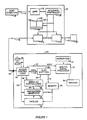
- a programmable hearing aid 20 is coupled to a host computer 25 by an interface unit 30.
- the system shown in Figure 1 is used to load new programs into the hearing aid 20. It can also be used to read the programs and other data stored inside the hearing aid 20.
- the hearing aid 20 also known as an auditory prosthesis, can store a number of distinct programs, or sets of parameter values, each designed for use in different audio environments. See U.S. Patent No. 4,425,481 (Mangold et al., 1984).
- hearing aid programs and “program data” are used herein to mean: specific settings of a predefined set of hearing aid parameters, selection of a signal processing configuration or strategy, selection of a particular algorithm or set of microprocessor instructions, modification of a hearing aid control program, and/or settings of coefficients in a auditory signal processing program.
- the hearing aid 20 stores a multiplicity of programs for controlling an analog signal processor 32, which amplifies and shapes input audio signals frcm microphone 34.
- a speaker 36 audibly transmits the resulting processing signals to the user.
- Programs or program data are stored in a memory buffer 38 which is also used to store datalogging information, as described in application serial no. 175,233, supra .
- each program is represented by sixty-eight bits of program data and 24 bits of datalogging data, and the memory 38 is used to store eight programs - for a total of 736 bits of program and datalogging data.
- the memory 38 which stores a total of 896 bits of data, is also used to store additional datalogging data not relevant to the present invention.
- the eight programs stored in memory 38 are linearly arranged in order of sensitivity.
- program selection buttons 42 and 44 the user can select new programs, with one button 42 being used to select programs with increasing sensitivity and the other button 44 being used to select programs with decreasing sensitivity.
- An access control circuit 48 and a serial I/O control circuit 50 together control several aspects of the hearing aid's operation, including the loading of newly selected programs into the signal processor 32, and communications via a serial input/output port 52.
- address generator 54 generates the address signals necessary for accessing the program data and datalogging data in the memory 38.
- the access control circuit 48 detects that the user has selected a new program, and sends a program selection signal on line 56 to the address generator 54. (This same signal is also used by the datalogging circuit 40 for datalogging purposes.)
- the access control circuit 48 also generates a muting signal XOFF on line 57 which causes the signal processor to stop its normal amplification functions. This prevents the hearing aid from generating loud and unpredictable sounds while new parameters are being loaded into the the signal processor 32. XOFF is disabled when the newly selected program is fully loaded into the signal processor 32. In other words, whenever a new program is selected, the hearing aid automatically stops amplifying audio input signals until the new program is fully loaded into the signal processor 32.
- the address generator 54 responds to the program selection signal on line 56 by loading the initial address for the selected program into its X and Y address buffers (not shown).
- the access control circuit 48 When a new program is selected, the access control circuit 48 also sends a program load signal on line 58 to the serial I/O control logic circuit 50.
- the serial I/O control logic circuit 50 controls the process of transmitting four sixteen-bit words from the memory 38 into a slave memory in the signal processor 32, four bits of program data to a tele-coil control circuit (not shown) and twenty-four bits of datalogging data to the datalog circuit 40.
- the serial logic circuit 50 For each of the sixteen-bit words to be transmitted through the shift register 62 to the signal processor 32, the serial logic circuit 50 generates a load signal on line 60 to load the currently addressed contents of the memory 38 in parallel into the sixteen-bit shift register 62, and then transmits a series of shift signals to shift the contents of the shift register 62 into the slave memory in the signal processor 32. In addition, after loading each sixteen-bit word into the shift register 62, the serial control circuit 50 sends a signal on line 64 to the address generator 54, causing the address generator to increment its internal address counter so as to point to the next word of the selected program.
- muting and “locking” are used in this description to mean inhibiting the signal processing (i.e., amplification and filtering) functions of the hearing aid 20.
- Terms such as “unlocking” and “to disable muting” mean the resumption of normal operation of the amplification and filtering functions of the hearing aid.
- FIG. 2 there is shown a more detailed diagram of the signal processor 32.
- the ccmponents outside the dashed boundaries of the signal processor 32 correspond to the items with like reference numerals in Figure 1.
- a telephone pickup 70 for assisting the user during telephone conversations.
- the signal processor 32 is a programmable processor whose function is controlled by the parameters stored in a sixty-four bit shift register slave memory 80. The process for loading the slave memory 80 with program data, using shift register 62, is described above. Eight of the parameters stored in the slave memory 80 are labelled TEL, MIC, FILTR, AGC LP, AGC HP, ATT LP, ATT HP, and OUTPUT AMP. For each of these parameters there is a corresponding circuit block shown in Figure 2, the function of which is controlled or modified in accordance with the current value of the corresponding parameter.
- the input signals from each of the input devices, microphone 34 and telephone pickup 70 are passed through preamplifiers 82 and 84 and digitally controlled attenuators ATT MIC 86 and ATT TEL 88.
- the resulting signals are then summed by summer 90.
- the output from summer 90 is passed through filter 92, which splits the signal into low and high pass signals LP and HP.
- the crossover frequency between the low- and high-pass channels can be varied digitally from 500 Hz to 4 KHz, in accordance with the value of the FILTR parameter stored in the slave memory 80.
- the low- and high-pass signals are processed in parallel by automatic-gain-controlled amplifiers 94 and 96 and then digitally controlled attenuators ATT HP 98 and ATT LP 100 before being summed together by summer SUM2 102.
- the thresholds of the automatic-gain-controlled amplifiers 94 and 96 are digitally controlled by threshold setting parameters AGC HP and AGC LP stored in the slave memory 80.
- An output amplifier 104 is provided for receiving the summed output of 102 and driving a speaker 36.
- an external output amplifier can be used to perform the driving function.
- a number of the components of the signal processor 32 are coupled to XOFF line 57. These components include the digitally controlled attenuators ATT MIC 86 and ATT TEL 88, summer 90, the automatic-gain-controlled amplifiers 94 and 96, and summer 102. All of these components are either disabled, or generate substantially attenuated and muted signals whenever the XOFF signal on line 57 is enabled. As a result, the signal processor's operation is substantially inhibited or muted when XOFF is enabled so as to protect the user's ears during program selection and the loading of new program data.
- the function of the access control logic circuit 48 is twofold: (1) to initiate the loading of selected programs when the user uses switches 42 and 44, and (2) to monitor the serial port 52 for "read” and "write” commands. This part of the discussion concerns how the hearing aid responds to read and write commands.
- a write command is a four bit signal having a value of "1100", followed by a two millisecond pause, followed by 896 bits of program data.
- the access control logic circuit 48 detects a write command bit sequence "1100" on the serial port 52, it prepares for receiving new program data by generating an XOFF signal on line 57 (to mute the hearing aid during the programming process), and by signaling the serial I/O control logic 64 and address generator circuit 54 to prepare for loading program data. More particularly, the address generator 54 resets its internal address counters to point at the beginning of the hearing aid's memory 38, and the serial I/O control logic 64 synchronizes its internal timer with the beginning of the program data.
- serial I/O control logic 64 shifts each bit of received data into the sixteen-bit shift register 62. Each set of sixteen bits of data is then loaded in parallel into the memory buffer 38. This process continues until all 896 bits (sixty four sets of sixteen-bit words) of program data have been received and loaded into the program memory 38.
- the hearing aid 20 remains muted at the end of the program loading process because it is possible that the program data may have been corrupted during the data transmission process.
- the memory interface unit 30 is programmed to read and verify the data stored in the hearing aid 20 immediately after new program data has been loaded into the hearing aid 20. Finally, after the interface unit has confirmed that the data read from the hearing aid matches the data it sent to the hearing aid, it sends an "Unlock" signal to the hearing aid.
- An unlock signal is a four bit signal having a value of "1101".
- a read command is a four bit signal having a value of "1110".
- the access control logic circuit 48 detects a read command on the serial port 52, it prepares for transmitting the entire ccntents of its memory buffer 38 by commanding the address generator 54 to reset its internal address counters to point at the beginning of the hearing aid's memory 38, and commanding the serial I/O control logic 64 to read and transmit all of the data in the memory 38.
- the entire programming process including the write, read and Unlock steps, takes almost exactly two seconds.
- the host computer 25 communicates with the hearing aid 20 through a memory interface unit 30.
- the interface unit 30 may be considered a slave-like extension of the host computer 25 in that its sole function is to perform tasks corresponding to commands sent to it by the host computer 25 via a serial communications line 110.
- the host computer is an IBM Model 50
- the memory interface unit 30 is one of the computer's peripheral devices.
- the serial interface line 110 is a single standard RS-232 serial line over which data is transmitted at a rate of 19200 baud.
- the memory interface unit 30 includes three communications circuits 112, 114 and 116 for communications over three data channels.
- Circuit 112 handles data transmissions with the host computer 25 over serial line 110.
- circuit 112 is a standard UART device.
- Circuits 114 and 116 handle data transmissions over two serial communication lines 118 and 120 to two hearing aids 20 and 20′.
- the hearing aid programs for each ear will often be different. It is therefore important that the program data for a person's left-side hearing aid not be loaded into the person's right-side hearing aid, and vice versa. For this reason the memory interface unit 30 has two distinct hearing aid communications ports or lines 118 and 120. In the preferred embodiments these ports are distinctly labelled "Left Ear” and "Right Ear” so that the user will have the correct program data loaded into each hearing aid to.
- Additional components of the memory interface unit 30 include a microprocessor (model Z80 made by Zilog) based controller 125 and a memory buffer 128.
- the memory buffer 128 is partitioned for convenience into three segments: segment 130 for storing program data received from the host computer, segment 132 for storing data received from a hearing aid 20, and segment 134 for storeing program parameters, data values, checksum values and other miscellaneous information needed by the controller 125.
- the memory interface unit 30 acts as a memory buffer for programs being loaded into a programmable hearing aid 20.
- the interface unit 30 also facilitates programming by automatically performing a program verification procedure that checks to see whether the program data stored in the hearing aid 20 is identical to the program data that was transmitted to the hearing aid.
- the interface unit 30 When the host computer 25 sends a command to the memory interface unit 30, the interface unit 30 performs the requested task and then repcrts back to the host, via the serial communications line 110, with a message, or data, or both, depending on the nature of the command.
- Communications between the memory interface and the hearing aids 20 and 20′ occur asynchronously at half duplex using pulse width modulation.
- Data flows at a rate of 1000 baud over communications lines 118 and 120, with each bit frame being 1 millisecond in duration.
- a bit frame starts with the communication line dropping from a high state to a low state, where the high state is a voltage potential of +1.3 volts and the low state is a voltage potential of - 1.3 volts.
- a data or bit value of "1" is encoded as a pulse with a width of 0.5 milliseccnd, while a bit value of "0" is encoded as a pulse with a width of just 0.25 millisecond.
- the software for the controller 125 is downloaded from the host computer 25 by a resident loader program in the interface unit 30.
- the software for the controller 125 can be stored in a read only memory.
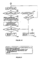
- Figures 3-10 are flow charts of the procedures used by the controller 125 in the memory interface unit 30 during the hearing aid programming process.
- the interface unit 30 can both program and interrogate the hearing aid 20 in response to corresponding commands from the host computer 25.
- the host computer 25 sends a command to the interface unit, it sends either a "hearing aid (HA) write” ccmmand or a "hearing aid (HA) read” command, along with a designation of either the left or right hearing aid port 118 or 120.
- the interface unit responds (box 150 in Figure 3) by selecting or enabling its Data I/O Card and selecting the left or right hearing aid port. The remainder of the interface unit's response to the host computer's command depends on whether the host sent a write or read command (box 152).
- Data I/O Card is a physically separate board in the memory interface unit 30 which has the contrcl circuitry for communicating with the hearing aid 20.
- the Data I/O Card corresponds to communication circuits 114 and 116 in Figure 1.
- the interface unit When the host sends a write command to the interface unit, the interface unit sets an internal counter called # _ATTEMPTS to a value of three, and calls a subroutine named READ_FROM_PC to receive a set of program data from the host.
- the READ_FROM_PC routine is described in more detail below with reference to Figures 4A-4B.
- the interface unit deselects its Data I/O Card, sends and error code "ERR602" to the host, and exits (box 158). Error code "ERR602" indicates a transmission problem between the host and the interface unit. When this happens the interface unit does not attempt to send the program data to the hearing aid 20.
- the interface unit After successfully receiving the program data from the host computer, the interface unit sends the received program data to the selected hearing aid, pauses briefly, reads the program data stored in the hearing aid, and then compares the program data received from the hearing aid with the program data sent (box 160). If the data received and the data sent match (box 162), an Unlock signal is sent to the hearing aid after a brief pause, the Data I/O Card is deselected, an "OK" message is sent to the host computer to indicate that the hearing aid was successfully programmed, and the routine exits (box 164).
- the #_ATTEMPTS variable is decremented (box 166). If less then three attempts have been made to program the hearing aid (i.e., if #_ATTEMPTS is greater than zero) (box 168), the hearing aid programming process is repeated beginning at box 160. After three unsuccessful attempts to program the hearing aid, the interface unit deselects the Data I/O Card, sends and error code "ERR601" to the host, and exits (box 170). Error code "ERR601" indicates a transmission problem between the interface unit 30 and the hearing aid 20.
- the interface unit When the host sends a read command (box 152), the interface unit reads the program data stored in the hearing aid (box 172). If all 896 bits of the hearing aid data are successfully received (box 174), an Unlock command is sent to the hearing aid (box 176). Then the hearing aid data is sent to the host computer, the Data I/O Card is deselected, and the routine exits (box 178).
- the interface unit If the hearing aid data is not successfully received (box 174), the interface unit overwrites the received data in its memory buffer 132 with "all ones" or "FF's" (box 180) and then sends this data to the host computer (indicating that it failed to read the hearing aid's memory), the Data I/O Card is deselected, and the routine exits (box 178).
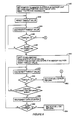
- Figures 4A-4B show the detailed procedure for receiving program data from the host computer.
- the interface indicates that it is ready to receive data from the host by sending a carriage return signal to the host, setting an internal counter for 112 bytes of data, and setting a timeout counter to a predefined delay value (box 190).
- the procedure for receiving the 112 bytes of program data is as follows.
- the interface unit polls its input buffer (box 192). If data has been not received from the host (box 194) the timeout counter is decremented (box 196) and the timeout counter is tested (box 198) to determine if communications with the host computer have failed. If timeout has not occurred the input buffer is polled once again (box 192). If timeout has occurred, however, the internal status of the interface unit is set to "ERROR" and the procedure aborts (see box 200 in Figure 4B).
- the host computer After 112 bytes of data have been sent by the host and received by the interface unit (box 204), the host computer sends a two byte checksum value corresponding to the program data that it just sent.
- a standard checksum formula is used to compute the checksums used in the preferred embodiment. As is well known to those skilled in the art, checksum values are often computed in a cumulative fashion as data is received, and the purpose of the checksum value is to detect data transmission errors.
- the interface unit polls its input buffer (box 210) and a timeout procedure (boxes 212, 214 and 216) is followed which is identical to the timeout procedure described above (boxes 194, 196 and 198).
- the procedure for receiving the most significant byte of the checksum (the checksum MSB) (boxes 220 - 228) is identical to the procedure for receiving the checksum LSB.
- checksum LSB and the checksum MSB After the checksum LSB and the checksum MSB have both been received from the host, these checksum values are compared with the checksum values ccmputed by the interface unit as it received the data from the host computer (box 230). If the checksum values match (box 232), the data from the host computer has been successfully received and interface sets its internal status to "OK” and exits from this procedure (box 234); otherwise, interface sets its status to "ERROR” (box 200) before exiting.
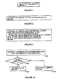
- the interface unit 30 sends data to the hearing aid 20 by sending a write command (i.e., a predefined four bit code, "1100"), waiting for two milliseconds, and then sending the 112 bytes of program data stored in its memory buffer 128 to the hearing aid.
- a write command i.e., a predefined four bit code, "1100”
- the program data is transmitted at a rate of 1000 bits per second, using pulse width modulation.
- the interface unit prepares for reading the 112 bytes of data stored in the hearing aid's memory 38 (shown in Figure 1) by setting a pointer to the portion 132 of its own memory 128 for storing data received from the hearing aid, setting a data counter for 112 bytes of data, and sending a read command to the hearing aid (box 240).
- a read command is a four bit signal having a binary value of "1110".
- the remainder of this subroutine is a loop (boxes 242 through 260) which is repeatedly executed, once for each bit of data received from the hearing aid. To receive 112 bytes of data, this loop is executed 896 times. The purpose of the instructions in the loop is to detect the falling edge, and then the rising edge of each pulse width encoded bit of data. As described above, each bit frame starts with the communication line 118 dropping from a high state to a low state. A data or bit value of "1" is encoded as a pulse with a width of 0.5 millisecond, while a bit value of "0" is encoded as a pulse with a width of just 0.25 millisecond.
- the first part of the data reading loop sets a timeout counter (e.g., to a value of 0.75 milliseconds) (box 242) and then waits for a low voltage level to be detected on the hearing aid communication line (boxes 244, 246 and 248).
- a low voltage level on the line marks the falling edge of a pulse, which is the beginning a new data bit. If a falling edge is not detected within the timeout period, there is a communications problem and the interface unit sets its internal status to "ERROR" (box 262) and exits back to the main routine (see Figure 3).
- the routine waits for 1/3 millisecond and then reads the state of the hearing aid ccmmunication line 118 to determine whether the data bit being read is a "1" or a "0" (box 250). If the line 118 is still low, the data bit being read is a "1" because the pulse width of data bits with a value of "1" is 0.5 millisecond. If the line 118 is high, the data bit being read is a "0" because "0" data bits have a pulse width of 0.25 millisecond.
- the state of the line is read as a "0" if the line is at a low voltage and is read as "1” if the line is at a high voltage. Therefore, to obtain the binary value of the data bit being read, the binary "value" of the data line 1/3 millisecond after the beginning of the pulse is inverted and stored in the interface unit's memory buffer.
- the routine looks for the end of the current data pulse by resetting the timeout counter (box 250) and waiting (boxes 252, 254 and 256) until the hearing aid communication line is found to be at a high voltage (i.e., +1.3 volts). If a high voltage is not detected within the timeout period, there is a communications problem and the interface unit sets its internal status to "ERROR" (box 262) and exits back to the main routine (see Figure 3).
- a high voltage i.e., +1.3 volts
- the PAUSE subroutine used by the main program is simply a four millisecond delay which enables the hearing aid to recover from a previously executed read or write command.
- the UNLOCK subroutine is used by the main program (see box 164) to "unlock the hearing aid” by sending an unlock command (a four bit signal having a value of "1101") to the hearing aid.
- the unlock command causes the hearing aid to turn off its XOFF signal so that the hearing aid can resume normal operation.
- the WRITE _TO_PC subroutine is used by the main program (see box 178) to send data read from a hearing aid 20 to the host computer 25.
- the interface 30 indicates that it is ready to send data to the host by sending a carriage return signal to the host. It then sends the 112 bytes of hearing aid data to the host computer (at 19200 baud using standard RS-232 communication protocols) while computing a checksum for this data. As noted above, the checksum is sent so that the host computer can determine whether the data sent by the interface unit has been corrupted by noise. Finally, the two bytes of the checksum are sent to the host before this subroutine exits back to the main routine.
- the COMPARE_DATA subroutine used by the main program compares the 112 bytes of data sent by the host computer with the 112 bytes of data received from the hearing aid after the hearing aid has been programmed with the data from the host computer (box 270). If the host data and hearing aid data match (box 272) the interface sets its internal status to "OK” (box 274) and exits back to the main routine (see Figure 3). Otherwise the interface sets its internal status to "ERROR"(box 276) before exiting back to the main routine.
Abstract
Description
- The present invention relates to hearing aid devices, and particularly to an interface and method or protocol for programming a programmable hearing aid.
- Programmable hearing aids, such as the hearing aid disclosed in U.S. Patent No. 4,425,481 (Mangold et al., 1984) can store a number of distinct programs, or sets of parameter values, each designed for use in different audio environments. For instance, a hearing aid that stores eight distinct programs can have programs for a variety of situations, such as conversing with one person in a quiet room, conversing with several persons in an otherwise fairly quiet environment, conversing with one or more persons in settings with increasing levels of background noise, walking or commuting environments with large noise variations, listening to music in a quiet room, and listening to music in a noisy environment. U.S. Patent No. 4,425,481 is hereby incorporated by reference.
- The various programs in a programmable hearing aid must be customized to compensate for an individual's particular hearing deficiencies. However, some aspects of hearing aid programming are inherently subjective on the part of the user - and therefore hearing aids often must be reprogrammed several times before an optimal set of programs is found. In addition, a person's hearing characteristics may change over time, requiring adjustment of the programs stored in a programmable hearing aid. As a result, programmable hearing aids should be easily reprogrammed.
- A copending application, No. EP89302689.8, entitled AUDITORY PROSTHESIS WITH DATALOGGING CAPABILITY, filed on March 17, 1989 discloses a datalogging system for generating a record of the frequency of usage of each of the programs in a programmable hearing aid.
- Another copending application, No. entitled HEARING AID PROGRAMMING INTERFACE, filed on the same date as this application, discloses a miniature interface in a hearing aid, and a corresponding connector, for connecting a hearing aid to a computer for reprogramming the device.
- When a programmable hearing aid is programmed with new data, or when a multiple-memory hearing aid is loaded with a new set of data, several considerations must be taken into account. In particular, the programming process should be as fast as possible while being verifiably error free.
- In addition, it is desirable to be able to program the hearing aid without removing the hearing aid fromn the user's ear. However, it would be unacceptable for the hearing aid to generate unpredictably loud and possibly injurious sounds during the programming procedure. In particular, during the programming or program loading process the signal processor in the hearing aid may be temporarily placed into an indeterminate state. This indeterminate state is caused by the fact that it takes a finite amount of time to load a new set of program data into the signal processor, and that the program characteristics of the signal processor during the loading of the program data will be unpredictable. Another problem with the loading of new program data while the hearing aid is still mounted in the user's ear is that the programming process may generate digital noise that affects the operation of the hearing aid.
- To prevent operation of the hearing aid when it is in an indeterminate state, and to prevent any possibility of unpleasant and possibly injurious sounds being generated during program selection and reprogramming, the present invention automatically mutes the hearing aids amplification functions during the loading of new program data. Muting is automatically terminated only when the newly loaded program data has been verified as error free. The muting function is also temporarily activated whenever the user switches programs so that the hearing aid's amplification functions are disabled until the new program has been fully loaded into the hearing aid's amplification control circuitry.
- In summary, the present invention is system and method for programming a programmable hearing aid. The programmable hearing aid has a serial data interface for receiving data transmissions, a decoder for decoding data transmissions, a program memory which stores program data values received via the serial interface, and read control logic that transmits the program data stored in the program memory when the decoder detects the receipt of a predefined read signal.
- Programming begins with the sending a set of program data values to the programmable hearing aid, preceded by a predefined write signal. The hearing aid automatically mutes its operation upon receiving the write signal. A first checksum value corresponding to the program data values sent to the programmable hearing aid is calculated.
- Next, the data stored in the hearing aid is checked by sending a predefined read signal to the hearing aid, causing the hearing aid to transmit the program data stored in its program memory. A second checksum value corresponding to the program data transmitted by the hearingaid is calculated and compared with the first checksum value. If the first and second checksum values do not match an error signal is generated and the hearing aid remains muted. If the checksum values do match, an unlock signal is sent to the hearing aid, causing the hearing aid to cease the muting of its operation.
- An example of the invention will now be described in conjunction with the accompanying drawings, in which:
- Figure 1 is a block diagram showing a hearing aid coupled to a hearing aid programming system.
- Figure 2 shows a more detailed block diagram of the analog portion of the hearing aid shown in Figure 1.
- Figures 3-10 are flow charts of the communications procedure used to program the hearing aid shown in Figure 1.
- Figure 3 is a flow chart of the procedure or protocol used for programming a programmable hearing aid.
- Figures 4A-4B are a flow chart of the procedure for receiving data from a host computer.
- Figure 5 is a flow chart of the procedure for sending data to a host computer.
- Figure 6 is a flow chart of the procedure for reading the data stored in the programmable hearing aid.
- Figures 7-10 are flow charts for the Pause, Unlock, Write to PC, and Compare Data subroutine procedures used by the procedure shown in Figure 3.
- In Figure 1 a
programmable hearing aid 20 is coupled to ahost computer 25 by aninterface unit 30. As will be described in more detail, the system shown in Figure 1 is used to load new programs into thehearing aid 20. It can also be used to read the programs and other data stored inside thehearing aid 20. - The
hearing aid 20, also known as an auditory prosthesis, can store a number of distinct programs, or sets of parameter values, each designed for use in different audio environments. See U.S. Patent No. 4,425,481 (Mangold et al., 1984). - The terms "hearing aid programs" and "program data" are used herein to mean: specific settings of a predefined set of hearing aid parameters, selection of a signal processing configuration or strategy, selection of a particular algorithm or set of microprocessor instructions, modification of a hearing aid control program, and/or settings of coefficients in a auditory signal processing program.
- The
hearing aid 20 stores a multiplicity of programs for controlling ananalog signal processor 32, which amplifies and shapes input audiosignals frcm microphone 34. Aspeaker 36 audibly transmits the resulting processing signals to the user. - Programs or program data are stored in a
memory buffer 38 which is also used to store datalogging information, as described in application serial no. 175,233, supra. In the preferred embodiment, each program is represented by sixty-eight bits of program data and 24 bits of datalogging data, and thememory 38 is used to store eight programs - for a total of 736 bits of program and datalogging data. Thememory 38, which stores a total of 896 bits of data, is also used to store additional datalogging data not relevant to the present invention. - For the convenience of the user, the eight programs stored in
memory 38 are linearly arranged in order of sensitivity. By pressingprogram selection buttons 42 and 44 the user can select new programs, with onebutton 42 being used to select programs with increasing sensitivity and the other button 44 being used to select programs with decreasing sensitivity. - An
access control circuit 48 and a serial I/O control circuit 50 together control several aspects of the hearing aid's operation, including the loading of newly selected programs into thesignal processor 32, and communications via a serial input/output port 52. In addition,address generator 54 generates the address signals necessary for accessing the program data and datalogging data in thememory 38. - Before explaining how new program data is stored in the
hearing aid 20, the operation of the hearing aid's memory access circuitry during program selection is provided as background information. - When the user depresses one of the program selection switches 42 or 44 and thereby selects a new program to be loaded into the
signal processor 32, the following sequence of events occurs. Theaccess control circuit 48 detects that the user has selected a new program, and sends a program selection signal online 56 to theaddress generator 54. (This same signal is also used by thedatalogging circuit 40 for datalogging purposes.) - At approximately the same time, the
access control circuit 48 also generates a muting signal XOFF online 57 which causes the signal processor to stop its normal amplification functions. This prevents the hearing aid from generating loud and unpredictable sounds while new parameters are being loaded into the thesignal processor 32. XOFF is disabled when the newly selected program is fully loaded into thesignal processor 32. In other words, whenever a new program is selected, the hearing aid automatically stops amplifying audio input signals until the new program is fully loaded into thesignal processor 32. - The
address generator 54 responds to the program selection signal online 56 by loading the initial address for the selected program into its X and Y address buffers (not shown). - When a new program is selected, the
access control circuit 48 also sends a program load signal online 58 to the serial I/Ocontrol logic circuit 50. In response, the serial I/Ocontrol logic circuit 50 controls the process of transmitting four sixteen-bit words from thememory 38 into a slave memory in thesignal processor 32, four bits of program data to a tele-coil control circuit (not shown) and twenty-four bits of datalogging data to thedatalog circuit 40. - For each of the sixteen-bit words to be transmitted through the
shift register 62 to thesignal processor 32, theserial logic circuit 50 generates a load signal online 60 to load the currently addressed contents of thememory 38 in parallel into the sixteen-bit shift register 62, and then transmits a series of shift signals to shift the contents of theshift register 62 into the slave memory in thesignal processor 32. In addition, after loading each sixteen-bit word into theshift register 62, theserial control circuit 50 sends a signal online 64 to theaddress generator 54, causing the address generator to increment its internal address counter so as to point to the next word of the selected program. - The terms "muting" and "locking" are used in this description to mean inhibiting the signal processing (i.e., amplification and filtering) functions of the
hearing aid 20. Terms such as "unlocking" and "to disable muting" mean the resumption of normal operation of the amplification and filtering functions of the hearing aid. - Referring to Figure 2, there is shown a more detailed diagram of the
signal processor 32. The ccmponents outside the dashed boundaries of thesignal processor 32 correspond to the items with like reference numerals in Figure 1. In addition, there is shown atelephone pickup 70 for assisting the user during telephone conversations. - The
signal processor 32 is a programmable processor whose function is controlled by the parameters stored in a sixty-four bit shiftregister slave memory 80. The process for loading theslave memory 80 with program data, usingshift register 62, is described above. Eight of the parameters stored in theslave memory 80 are labelled TEL, MIC, FILTR, AGC LP, AGC HP, ATT LP, ATT HP, and OUTPUT AMP. For each of these parameters there is a corresponding circuit block shown in Figure 2, the function of which is controlled or modified in accordance with the current value of the corresponding parameter. - Briefly reviewing the operation of the
signal processor 32, the input signals from each of the input devices,microphone 34 andtelephone pickup 70, are passed throughpreamplifiers attenuators ATT MIC 86 andATT TEL 88. The resulting signals are then summed bysummer 90. The output fromsummer 90 is passed throughfilter 92, which splits the signal into low and high pass signals LP and HP. The crossover frequency between the low- and high-pass channels can be varied digitally from 500 Hz to 4 KHz, in accordance with the value of the FILTR parameter stored in theslave memory 80. - The low- and high-pass signals are processed in parallel by automatic-gain-controlled
amplifiers attenuators ATT HP 98 andATT LP 100 before being summed together bysummer SUM2 102. The thresholds of the automatic-gain-controlledamplifiers slave memory 80. - An
output amplifier 104 is provided for receiving the summed output of 102 and driving aspeaker 36. Alternatively, an external output amplifier can be used to perform the driving function. - As shown in Figure 2, a number of the components of the
signal processor 32 are coupled toXOFF line 57. These components include the digitally controlledattenuators ATT MIC 86 andATT TEL 88,summer 90, the automatic-gain-controlledamplifiers summer 102. All of these components are either disabled, or generate substantially attenuated and muted signals whenever the XOFF signal online 57 is enabled. As a result, the signal processor's operation is substantially inhibited or muted when XOFF is enabled so as to protect the user's ears during program selection and the loading of new program data. - During normal operation of the
hearing aid 20, the function of the accesscontrol logic circuit 48 is twofold: (1) to initiate the loading of selected programs when the user usesswitches 42 and 44, and (2) to monitor theserial port 52 for "read" and "write" commands. This part of the discussion concerns how the hearing aid responds to read and write commands. - A write command is a four bit signal having a value of "1100", followed by a two millisecond pause, followed by 896 bits of program data. When the access
control logic circuit 48 detects a write command bit sequence "1100" on theserial port 52, it prepares for receiving new program data by generating an XOFF signal on line 57 (to mute the hearing aid during the programming process), and by signaling the serial I/O control logic 64 andaddress generator circuit 54 to prepare for loading program data. More particularly, theaddress generator 54 resets its internal address counters to point at the beginning of the hearing aid'smemory 38, and the serial I/O control logic 64 synchronizes its internal timer with the beginning of the program data. - As the program data is received, the serial I/
O control logic 64 shifts each bit of received data into the sixteen-bit shift register 62. Each set of sixteen bits of data is then loaded in parallel into thememory buffer 38. This process continues until all 896 bits (sixty four sets of sixteen-bit words) of program data have been received and loaded into theprogram memory 38. - The
hearing aid 20 remains muted at the end of the program loading process because it is possible that the program data may have been corrupted during the data transmission process. As will be described below, thememory interface unit 30 is programmed to read and verify the data stored in thehearing aid 20 immediately after new program data has been loaded into thehearing aid 20. Finally, after the interface unit has confirmed that the data read from the hearing aid matches the data it sent to the hearing aid, it sends an "Unlock" signal to the hearing aid. - An unlock signal is a four bit signal having a value of "1101". When the access
control logic circuit 48 detects an unlock signal on the serial port, one of the new programs is loaded into thesignal processor 32, using the program selection process described above. Then the access control logic turns off the XOFF signal so that the hearing aid can resume normal operation. Thus, the unlock command "unlocks" the hearing aid in that it enables the hearing aid to resume normal operation (i.e., signal processing) after storing new program data. - A read command is a four bit signal having a value of "1110". When the access
control logic circuit 48 detects a read command on theserial port 52, it prepares for transmitting the entire ccntents of itsmemory buffer 38 by commanding theaddress generator 54 to reset its internal address counters to point at the beginning of the hearing aid'smemory 38, and commanding the serial I/O control logic 64 to read and transmit all of the data in thememory 38. - Sixteen bits at a time, data from the
memory 38 is loaded in parallel into the sixteen-bit shift register 62. Each set of sixteen bits of data is then shifted out, overdata line 108 to theserial port 52, while theaddress generator 54 increments its address counters to point at the next sixteen bit word in thememory buffer 38. This process continues until all 896 bits (sixty four sets of sixteen-bit words) of data in thememory buffer 38 have been read and transmitted to thememory interface unit 30. - If the
memory interface unit 30 finds no errors in the data read from thehearing aid 20, the entire programming process, including the write, read and Unlock steps, takes almost exactly two seconds. - The
host computer 25 communicates with thehearing aid 20 through amemory interface unit 30. Theinterface unit 30 may be considered a slave-like extension of thehost computer 25 in that its sole function is to perform tasks corresponding to commands sent to it by thehost computer 25 via aserial communications line 110. - In the preferred embodiment the host computer is an
IBM Model 50, and thememory interface unit 30 is one of the computer's peripheral devices. Theserial interface line 110 is a single standard RS-232 serial line over which data is transmitted at a rate of 19200 baud. - The
memory interface unit 30 includes threecommunications circuits Circuit 112 handles data transmissions with thehost computer 25 overserial line 110. In thepreferred embodiment circuit 112 is a standard UART device.Circuits serial communication lines hearing aids - It should be noted that for persons using two hearing aids, the hearing aid programs for each ear will often be different. It is therefore important that the program data for a person's left-side hearing aid not be loaded into the person's right-side hearing aid, and vice versa. For this reason the
memory interface unit 30 has two distinct hearing aid communications ports orlines - Additional components of the
memory interface unit 30 include a microprocessor (model Z80 made by Zilog) basedcontroller 125 and amemory buffer 128. Thememory buffer 128 is partitioned for convenience into three segments:segment 130 for storing program data received from the host computer,segment 132 for storing data received from ahearing aid 20, andsegment 134 for storeing program parameters, data values, checksum values and other miscellaneous information needed by thecontroller 125. - The
memory interface unit 30 acts as a memory buffer for programs being loaded into aprogrammable hearing aid 20. Theinterface unit 30 also facilitates programming by automatically performing a program verification procedure that checks to see whether the program data stored in thehearing aid 20 is identical to the program data that was transmitted to the hearing aid. - When the
host computer 25 sends a command to thememory interface unit 30, theinterface unit 30 performs the requested task and then repcrts back to the host, via theserial communications line 110, with a message, or data, or both, depending on the nature of the command. - Communications between the memory interface and the hearing aids 20 and 20′ occur asynchronously at half duplex using pulse width modulation. Data flows at a rate of 1000 baud over
communications lines - Using standard microcontroller technology, the software for the
controller 125 is downloaded from thehost computer 25 by a resident loader program in theinterface unit 30. In other embodiments of the invention the software for thecontroller 125 can be stored in a read only memory. - Figures 3-10 are flow charts of the procedures used by the
controller 125 in thememory interface unit 30 during the hearing aid programming process. - Referring to Figure 3, the
interface unit 30 can both program and interrogate thehearing aid 20 in response to corresponding commands from thehost computer 25. When thehost computer 25 sends a command to the interface unit, it sends either a "hearing aid (HA) write" ccmmand or a "hearing aid (HA) read" command, along with a designation of either the left or righthearing aid port box 150 in Figure 3) by selecting or enabling its Data I/O Card and selecting the left or right hearing aid port. The remainder of the interface unit's response to the host computer's command depends on whether the host sent a write or read command (box 152). - Note that in the preferred embodiment the "Data I/O Card" is a physically separate board in the
memory interface unit 30 which has the contrcl circuitry for communicating with thehearing aid 20. Thus the Data I/O Card corresponds tocommunication circuits - When the host sends a write command to the interface unit, the interface unit sets an internal counter called # _ATTEMPTS to a value of three, and calls a subroutine named READ_FROM_PC to receive a set of program data from the host. The READ_FROM_PC routine is described in more detail below with reference to Figures 4A-4B.
- If the READ_FROM_PC routine fails to successfully receive the program data from the host computer (box 156), the interface unit deselects its Data I/O Card, sends and error code "ERR602" to the host, and exits (box 158). Error code "ERR602" indicates a transmission problem between the host and the interface unit. When this happens the interface unit does not attempt to send the program data to the
hearing aid 20. - After successfully receiving the program data from the host computer, the interface unit sends the received program data to the selected hearing aid, pauses briefly, reads the program data stored in the hearing aid, and then compares the program data received from the hearing aid with the program data sent (box 160). If the data received and the data sent match (box 162), an Unlock signal is sent to the hearing aid after a brief pause, the Data I/O Card is deselected, an "OK" message is sent to the host computer to indicate that the hearing aid was successfully programmed, and the routine exits (box 164).
- If the data received frcm the hearing aid does not match the data sent match (box 162), the #_ATTEMPTS variable is decremented (box 166). If less then three attempts have been made to program the hearing aid (i.e., if #_ATTEMPTS is greater than zero) (box 168), the hearing aid programming process is repeated beginning at
box 160. After three unsuccessful attempts to program the hearing aid, the interface unit deselects the Data I/O Card, sends and error code "ERR601" to the host, and exits (box 170). Error code "ERR601" indicates a transmission problem between theinterface unit 30 and thehearing aid 20. - When the host sends a read command (box 152), the interface unit reads the program data stored in the hearing aid (box 172). If all 896 bits of the hearing aid data are successfully received (box 174), an Unlock command is sent to the hearing aid (box 176). Then the hearing aid data is sent to the host computer, the Data I/O Card is deselected, and the routine exits (box 178).
- If the hearing aid data is not successfully received (box 174), the interface unit overwrites the received data in its
memory buffer 132 with "all ones" or "FF's" (box 180) and then sends this data to the host computer (indicating that it failed to read the hearing aid's memory), the Data I/O Card is deselected, and the routine exits (box 178). - Figures 4A-4B show the detailed procedure for receiving program data from the host computer. The interface indicates that it is ready to receive data from the host by sending a carriage return signal to the host, setting an internal counter for 112 bytes of data, and setting a timeout counter to a predefined delay value (box 190).
- The procedure for receiving the 112 bytes of program data is as follows. The interface unit polls its input buffer (box 192). If data has been not received from the host (box 194) the timeout counter is decremented (box 196) and the timeout counter is tested (box 198) to determine if communications with the host computer have failed. If timeout has not occurred the input buffer is polled once again (box 192). If timeout has occurred, however, the internal status of the interface unit is set to "ERROR" and the procedure aborts (see
box 200 in Figure 4B). - When data is received from the host computer, it is stored in the interface's internal memory and the received data is used to update an internal checksum value (box 202), as explained in more detail belcw. In addition, the data received is echoed (i.e., transmitted) back to the host computer so that the host can confirm that the data has been properly received, and the timeout counter is reset to its original delay value (box 202). This data receiving process continues until 112 bytes of data have been received from the host (box 204) or a timeout occurs (box 196).
- After 112 bytes of data have been sent by the host and received by the interface unit (box 204), the host computer sends a two byte checksum value corresponding to the program data that it just sent. A standard checksum formula is used to compute the checksums used in the preferred embodiment. As is well known to those skilled in the art, checksum values are often computed in a cumulative fashion as data is received, and the purpose of the checksum value is to detect data transmission errors.
- While waiting to receive the least significant byte (the "checksum LSB") of the checksum value from the host computer, the interface unit polls its input buffer (box 210) and a timeout procedure (
boxes boxes - When the checksum LSB data is received from the host computer, it is stored in the interface's internal memory and echoed back to the host computer (box 218). The timeout counter is also reset to its original delay value (box 218).
- Continuing on Figure 4B, the procedure for receiving the most significant byte of the checksum (the checksum MSB) (boxes 220 - 228) is identical to the procedure for receiving the checksum LSB.
- After the checksum LSB and the checksum MSB have both been received from the host, these checksum values are compared with the checksum values ccmputed by the interface unit as it received the data from the host computer (box 230). If the checksum values match (box 232), the data from the host computer has been successfully received and interface sets its internal status to "OK" and exits from this procedure (box 234); otherwise, interface sets its status to "ERROR" (box 200) before exiting.
- Referring to Figure 5, the
interface unit 30 sends data to thehearing aid 20 by sending a write command (i.e., a predefined four bit code, "1100"), waiting for two milliseconds, and then sending the 112 bytes of program data stored in itsmemory buffer 128 to the hearing aid. As described above, the program data is transmitted at a rate of 1000 bits per second, using pulse width modulation. - Referring to Figure 6, the interface unit prepares for reading the 112 bytes of data stored in the hearing aid's memory 38 (shown in Figure 1) by setting a pointer to the
portion 132 of itsown memory 128 for storing data received from the hearing aid, setting a data counter for 112 bytes of data, and sending a read command to the hearing aid (box 240). As described above, a read command is a four bit signal having a binary value of "1110". - The remainder of this subroutine is a loop (
boxes 242 through 260) which is repeatedly executed, once for each bit of data received from the hearing aid. To receive 112 bytes of data, this loop is executed 896 times. The purpose of the instructions in the loop is to detect the falling edge, and then the rising edge of each pulse width encoded bit of data. As described above, each bit frame starts with thecommunication line 118 dropping from a high state to a low state. A data or bit value of "1" is encoded as a pulse with a width of 0.5 millisecond, while a bit value of "0" is encoded as a pulse with a width of just 0.25 millisecond. - The first part of the data reading loop sets a timeout counter (e.g., to a value of 0.75 milliseconds) (box 242) and then waits for a low voltage level to be detected on the hearing aid communication line (
boxes - After the beginning of a data pulse has been detected, the routine waits for 1/3 millisecond and then reads the state of the hearing
aid ccmmunication line 118 to determine whether the data bit being read is a "1" or a "0" (box 250). If theline 118 is still low, the data bit being read is a "1" because the pulse width of data bits with a value of "1" is 0.5 millisecond. If theline 118 is high, the data bit being read is a "0" because "0" data bits have a pulse width of 0.25 millisecond. - Using standard binary logic, the state of the line is read as a "0" if the line is at a low voltage and is read as "1" if the line is at a high voltage. Therefore, to obtain the binary value of the data bit being read, the binary "value" of the data line 1/3 millisecond after the beginning of the pulse is inverted and stored in the interface unit's memory buffer.
- Next, the routine looks for the end of the current data pulse by resetting the timeout counter (box 250) and waiting (
boxes - When the end of each data pulse is detected (box 256), the data counter is decremented (box 258) and tested to determine if all 896 bits of data have been received (box 260). If not, the procedure resumes at the beginning of the data reading loop (box 242). When all of the data has been received the interface sets its internal status to "OK" (box 264) and exits back to the main routine (see Figure 3).
- Referring to Figures 3 and 7, the PAUSE subroutine used by the main program (see
boxes 160 and 164) is simply a four millisecond delay which enables the hearing aid to recover from a previously executed read or write command. - Referring to Figures 3 and 8, the UNLOCK subroutine is used by the main program (see box 164) to "unlock the hearing aid" by sending an unlock command (a four bit signal having a value of "1101") to the hearing aid. The unlock command causes the hearing aid to turn off its XOFF signal so that the hearing aid can resume normal operation.
- Referring to Figures 3 and 9, the WRITE _TO_PC subroutine is used by the main program (see box 178) to send data read from a
hearing aid 20 to thehost computer 25. Theinterface 30 indicates that it is ready to send data to the host by sending a carriage return signal to the host. It then sends the 112 bytes of hearing aid data to the host computer (at 19200 baud using standard RS-232 communication protocols) while computing a checksum for this data. As noted above, the checksum is sent so that the host computer can determine whether the data sent by the interface unit has been corrupted by noise. Finally, the two bytes of the checksum are sent to the host before this subroutine exits back to the main routine. - Referring to Figures 3 and 10, the COMPARE_DATA subroutine used by the main program (see box 160) compares the 112 bytes of data sent by the host computer with the 112 bytes of data received from the hearing aid after the hearing aid has been programmed with the data from the host computer (box 270). If the host data and hearing aid data match (box 272) the interface sets its internal status to "OK" (box 274) and exits back to the main routine (see Figure 3). Otherwise the interface sets its internal status to "ERROR"(box 276) before exiting back to the main routine.
- While the present inventicn has been described with reference to a few specific embodiments, the description is illustrative of the inventicn and is not to be construed as limiting the invention. Various modifications may occur to those skilled in the art without departing from the true spirit and scope of the invention as defined by the appended claims.
Claims (12)
programmable signal processing means for filtering and amplifying auditory signals in accordance with a set of program data;
program loading means coupled to said signal processing means for loading a specified set of program data into said signal processing means;
and muting means coupled to said signal processing means for temporarily muting said signal processing means while said program loading means loads a set of program data into said signal processing means.
reprogramming means for loading sets of program data from an external source into said memory means;
said muting means coupled to said reprogramming means and including means for muting said signal processing means while said reprogramming means loads program data from an external source into said memory means.
programmable signal processing means for filtering and amplifying auditory signals in accordance with a set of program data;
programming means coupled to said signal processing means for enabling said signal processing means to use a specified set of program data; said programming means including memory means for storing a plurality of distinct sets of program data;
reprogramming means for loading sets of program data from an external source into said memory means;
and muting means coupled to said reprogramming means and said signal processing means for muting said signal processing means while said reprogramming means loads program data from an external source into said memory means.
said muting means including means for temporarily muting said signal processing means when said program selection means generates a program selection signal until said signal processing means is enabled to use a corresponding set of program data.
programmable signal processing means for filtering and amplifying auditory signals in accordance with a set of program data;
programming means coupled to said signal processing means for changing the program data used by said signal processing means; and
muting means coupled to said programming means and said signal processing means for temporarily muting said signal processing means while said programming means changes the program data used by said signal processing means.
responding to a program selection signal by changing the program data used by said signal processing means; and
temporarily muting said signal processing means while said programming means changes the program data used by said signal processing means.
responding to an externally generated write data signal by loading program data from an external source into said memory means in the hearing aid;
and muting said signal processing means while said reprogramming means loads program data from an external source into said memory means.
said muting step including muting said signal processing means while program data from an external source is being loaded into said memory means and continuing to mute said signal processing means until the completion of said step of changing the program data used by said signal processing means.
providing a programmable hearing aid with receiving means for receiving data transmissions, and memory means coupled to said receiving means for storing program data values received via said receiving means;
sending a predefined write signal and then a set of program data values to the receiving means of the programmable hearing aid;
automatically muting the operation of said programmable hearing aid upon receiving the predefined write signal, and then storing the following program data values in the hearing aid's memory means;
sending an unlock signal to the programmable hearing aid after the set of program data values has been stored in the hearing aid memory means;
said programmable hearing aid responding to said unlock signal by ceasing muting the operation of the programmable hearing aid.
providing a programmable hearing aid with receiving means for receiving data transmissions, decoding means for decoding said data transmissions, memory means coupled to said receiving means and decoding means for storing program data values received via said receiving means, and read control means coupled to said memory means and said decoding means for transmitting data stored in said memory means when said decoding means detects the receipt of a predefined read signal;
sending a set of program data values to the receiving means of the programmable hearing aid, preceded by a predefined write signal;
automatically muting the operation of said programmable hearing aid upon receiving the predefined write signal;
calculating a first checksum value corresponding to the program data values sent to the programmable hearing aid;
sending a predefined read signal to the receiving means of the programmable hearing aid;
said read control means of the programmable hearing and responding to said predefined read signal by transmitting the program data stored in the programmable hearing aid;
calculating a second checksum value corresponding to the program data transmitted from the programmable hearing aid;
comparing the first and second checksum values;
generating an error signal when said first and second checksum values do not match; and
sending an unlock signal to the programmable hearing aid when said first and second checksum values do match;
said programmable hearing aid responding to said unlock signal by ceasing muting the operation of the programmable hearing aid.
Applications Claiming Priority (2)
| Application Number | Priority Date | Filing Date | Title |
|---|---|---|---|
| US192259 | 1988-05-10 | ||
| US07/192,259 US4989251A (en) | 1988-05-10 | 1988-05-10 | Hearing aid programming interface and method |
Publications (3)
| Publication Number | Publication Date |
|---|---|
| EP0341903A2 true EP0341903A2 (en) | 1989-11-15 |
| EP0341903A3 EP0341903A3 (en) | 1991-05-08 |
| EP0341903B1 EP0341903B1 (en) | 1994-11-09 |
Family
ID=22708923
Family Applications (1)
| Application Number | Title | Priority Date | Filing Date |
|---|---|---|---|
| EP89304487A Expired - Lifetime EP0341903B1 (en) | 1988-05-10 | 1989-05-04 | Hearing aid programming interface and method |
Country Status (6)
| Country | Link |
|---|---|
| US (1) | US4989251A (en) |
| EP (1) | EP0341903B1 (en) |
| JP (1) | JP2965995B2 (en) |
| AU (1) | AU610391B2 (en) |
| CA (1) | CA1331651C (en) |
| DE (1) | DE68919270T2 (en) |
Cited By (20)
| Publication number | Priority date | Publication date | Assignee | Title |
|---|---|---|---|---|
| EP0537026A2 (en) * | 1991-10-11 | 1993-04-14 | Unitron Industries Ltd. | Portable programmer for hearing aids |
| WO1997017819A1 (en) * | 1995-11-07 | 1997-05-15 | Siemens Hearing Instruments, Inc. | System for programming programmable hearing aids and updating database of patient information |
| DE19625639A1 (en) * | 1996-06-26 | 1998-01-02 | Siemens Audiologische Technik | Programmable circuit for use in hearing aid |
| FR2767247A1 (en) * | 1997-08-11 | 1999-02-12 | Siemens Audiologische Technik | Digital sound signal processing circuit for hearing aid |
| US5909497A (en) * | 1996-10-10 | 1999-06-01 | Alexandrescu; Eugene | Programmable hearing aid instrument and programming method thereof |
| WO2000016589A1 (en) * | 1998-09-17 | 2000-03-23 | Sonic Innovations, Inc. | Two line variable word length serial interface |
| US6313773B1 (en) | 2000-01-26 | 2001-11-06 | Sonic Innovations, Inc. | Multiplierless interpolator for a delta-sigma digital to analog converter |
| EP1206163A1 (en) * | 2000-11-14 | 2002-05-15 | GN ReSound as | A hearing aid with error protected data storage |
| US6408318B1 (en) | 1999-04-05 | 2002-06-18 | Xiaoling Fang | Multiple stage decimation filter |
| US6556686B1 (en) | 1999-04-14 | 2003-04-29 | Siemens Audiologische Technik Gmbh | Programmable hearing aid device and method for operating a programmable hearing aid device |
| US6574342B1 (en) | 1998-03-17 | 2003-06-03 | Sonic Innovations, Inc. | Hearing aid fitting system |
| EP1320279A1 (en) * | 2002-06-10 | 2003-06-18 | Phonak Ag | Method for handling data of a hearing device and hearing device |
| US6885752B1 (en) | 1994-07-08 | 2005-04-26 | Brigham Young University | Hearing aid device incorporating signal processing techniques |
| US7054957B2 (en) | 1997-01-13 | 2006-05-30 | Micro Ear Technology, Inc. | System for programming hearing aids |
| US7715576B2 (en) | 2001-04-27 | 2010-05-11 | Dr. Ribic Gmbh | Method for controlling a hearing aid |
| US7787647B2 (en) | 1997-01-13 | 2010-08-31 | Micro Ear Technology, Inc. | Portable system for programming hearing aids |
| US8300862B2 (en) | 2006-09-18 | 2012-10-30 | Starkey Kaboratories, Inc | Wireless interface for programming hearing assistance devices |
| US8965016B1 (en) | 2013-08-02 | 2015-02-24 | Starkey Laboratories, Inc. | Automatic hearing aid adaptation over time via mobile application |
| US9344817B2 (en) | 2000-01-20 | 2016-05-17 | Starkey Laboratories, Inc. | Hearing aid systems |
| US10284978B2 (en) | 2005-10-18 | 2019-05-07 | Widex A/S | Equipment for programming a hearing aid and a hearing aid |
Families Citing this family (55)
| Publication number | Priority date | Publication date | Assignee | Title |
|---|---|---|---|---|
| DE3834962A1 (en) * | 1988-10-13 | 1990-04-19 | Siemens Ag | DIGITAL PROGRAMMING DEVICE FOR HOUR DEVICES |
| DE3900588A1 (en) * | 1989-01-11 | 1990-07-19 | Toepholm & Westermann | REMOTE CONTROLLED, PROGRAMMABLE HOUR DEVICE SYSTEM |
| US5226086A (en) * | 1990-05-18 | 1993-07-06 | Minnesota Mining And Manufacturing Company | Method, apparatus, system and interface unit for programming a hearing aid |
| US5197332A (en) * | 1992-02-19 | 1993-03-30 | Calmed Technology, Inc. | Headset hearing tester and hearing aid programmer |
| DE4321788C1 (en) * | 1993-06-30 | 1994-08-18 | Siemens Audiologische Technik | Interface for serial data transmission between a hearing aid and a control device |
| US5608803A (en) * | 1993-08-05 | 1997-03-04 | The University Of New Mexico | Programmable digital hearing aid |
| EP0676909A1 (en) * | 1994-03-31 | 1995-10-11 | Siemens Audiologische Technik GmbH | Programmable hearing aid |
| US5502769A (en) * | 1994-04-28 | 1996-03-26 | Starkey Laboratories, Inc. | Interface module for programmable hearing instrument |
| US8085959B2 (en) * | 1994-07-08 | 2011-12-27 | Brigham Young University | Hearing compensation system incorporating signal processing techniques |
| US5500902A (en) * | 1994-07-08 | 1996-03-19 | Stockham, Jr.; Thomas G. | Hearing aid device incorporating signal processing techniques |
| US5581747A (en) * | 1994-11-25 | 1996-12-03 | Starkey Labs., Inc. | Communication system for programmable devices employing a circuit shift register |
| US5862238A (en) * | 1995-09-11 | 1999-01-19 | Starkey Laboratories, Inc. | Hearing aid having input and output gain compression circuits |
| US5822442A (en) * | 1995-09-11 | 1998-10-13 | Starkey Labs, Inc. | Gain compression amplfier providing a linear compression function |
| EP0814634B1 (en) * | 1996-06-21 | 2002-10-02 | Siemens Audiologische Technik GmbH | Programmable hearing-aid system and method for determining an optimal set of parameters in an acoustic prosthesis |
| US6058197A (en) * | 1996-10-11 | 2000-05-02 | Etymotic Research | Multi-mode portable programming device for programmable auditory prostheses |
| US6424722B1 (en) * | 1997-01-13 | 2002-07-23 | Micro Ear Technology, Inc. | Portable system for programming hearing aids |
| US6236731B1 (en) | 1997-04-16 | 2001-05-22 | Dspfactory Ltd. | Filterbank structure and method for filtering and separating an information signal into different bands, particularly for audio signal in hearing aids |
| JPH1169499A (en) * | 1997-07-18 | 1999-03-09 | Koninkl Philips Electron Nv | Hearing aid, remote control device and system |
| JPH1136974A (en) * | 1997-07-24 | 1999-02-09 | Mitsubishi Electric Corp | Controller for vehicle |
| JP3626328B2 (en) * | 1997-07-24 | 2005-03-09 | 三菱電機株式会社 | Vehicle control device |
| US6366863B1 (en) * | 1998-01-09 | 2002-04-02 | Micro Ear Technology Inc. | Portable hearing-related analysis system |
| US6094492A (en) * | 1999-05-10 | 2000-07-25 | Boesen; Peter V. | Bone conduction voice transmission apparatus and system |
| DE59906049D1 (en) * | 1999-07-29 | 2003-07-24 | Phonak Ag Staefa | SYSTEM FOR ADJUSTING AT LEAST ONE HEARING AID |
| US6379314B1 (en) | 2000-06-19 | 2002-04-30 | Health Performance, Inc. | Internet system for testing hearing |
| DE10038118A1 (en) * | 2000-08-04 | 2002-02-21 | Optikom Gmbh | Hearing-aid adjustment method involves establishing long-distance data transmission over interface, for communicating operation status information of hearing aid |
| DE10046938A1 (en) * | 2000-09-21 | 2002-04-25 | Implex Ag Hearing Technology I | At least partially implantable hearing system with direct mechanical stimulation of a lymphatic space in the inner ear |
| US6633202B2 (en) | 2001-04-12 | 2003-10-14 | Gennum Corporation | Precision low jitter oscillator circuit |
| EP1251714B2 (en) | 2001-04-12 | 2015-06-03 | Sound Design Technologies Ltd. | Digital hearing aid system |
| CA2382358C (en) * | 2001-04-18 | 2007-01-09 | Gennum Corporation | Digital quasi-rms detector |
| ATE318062T1 (en) * | 2001-04-18 | 2006-03-15 | Gennum Corp | MULTI-CHANNEL HEARING AID WITH TRANSMISSION POSSIBILITIES BETWEEN THE CHANNELS |
| US20020191800A1 (en) * | 2001-04-19 | 2002-12-19 | Armstrong Stephen W. | In-situ transducer modeling in a digital hearing instrument |
| DK1284587T3 (en) * | 2001-08-15 | 2011-10-31 | Sound Design Technologies Ltd | Reconfigurable low energy hearing aid |
| US20040171965A1 (en) * | 2001-10-02 | 2004-09-02 | Fischer-Zoth Gmbh | Portable handheld hearing screening device and method with internet access and link to hearing screening database |
| DE10152197B4 (en) * | 2001-10-23 | 2009-07-09 | Siemens Audiologische Technik Gmbh | Method for programming a hearing aid, programming device and remote control for the hearing aid |
| DE60329709D1 (en) * | 2002-12-18 | 2009-11-26 | Bernafon Ag | RPROGRAMM HEARING AID |
| JP4173139B2 (en) * | 2003-03-19 | 2008-10-29 | ヴェーデクス・アクティーセルスカプ | Method for programming a hearing aid with a programming device |
| US7945065B2 (en) * | 2004-05-07 | 2011-05-17 | Phonak Ag | Method for deploying hearing instrument fitting software, and hearing instrument adapted therefor |
| JP4960360B2 (en) | 2005-08-23 | 2012-06-27 | ヴェーデクス・アクティーセルスカプ | Hearing aid with expanded acoustic bandwidth |
| US7496695B2 (en) * | 2005-09-29 | 2009-02-24 | P.A. Semi, Inc. | Unified DMA |
| US7933419B2 (en) * | 2005-10-05 | 2011-04-26 | Phonak Ag | In-situ-fitted hearing device |
| DK1938659T3 (en) * | 2005-10-17 | 2016-09-26 | Widex As | Høreapparat med valgbare programmer, og fremgangsmåde til at ændre programmet i et høreapparat |
| CN101310564A (en) * | 2005-11-18 | 2008-11-19 | 皇家飞利浦电子股份有限公司 | Signal processing system, for example sound signal processing system or a hearing aid device |
| US7747030B2 (en) * | 2006-02-17 | 2010-06-29 | Zounds Hearing, Inc. | Method for identifying a hearing aid |
| US7986790B2 (en) | 2006-03-14 | 2011-07-26 | Starkey Laboratories, Inc. | System for evaluating hearing assistance device settings using detected sound environment |
| JP4860748B2 (en) | 2006-03-31 | 2012-01-25 | ヴェーデクス・アクティーセルスカプ | Hearing aid fitting method, hearing aid fitting system, and hearing aid |
| US7966309B2 (en) | 2007-01-17 | 2011-06-21 | Google Inc. | Providing relevance-ordered categories of information |
| US8571244B2 (en) * | 2008-03-25 | 2013-10-29 | Starkey Laboratories, Inc. | Apparatus and method for dynamic detection and attenuation of periodic acoustic feedback |
| US9729976B2 (en) * | 2009-12-22 | 2017-08-08 | Starkey Laboratories, Inc. | Acoustic feedback event monitoring system for hearing assistance devices |
| US8942398B2 (en) | 2010-04-13 | 2015-01-27 | Starkey Laboratories, Inc. | Methods and apparatus for early audio feedback cancellation for hearing assistance devices |
| US8917891B2 (en) | 2010-04-13 | 2014-12-23 | Starkey Laboratories, Inc. | Methods and apparatus for allocating feedback cancellation resources for hearing assistance devices |
| US9654885B2 (en) | 2010-04-13 | 2017-05-16 | Starkey Laboratories, Inc. | Methods and apparatus for allocating feedback cancellation resources for hearing assistance devices |
| RU2623801C1 (en) * | 2013-07-26 | 2017-06-29 | Интел Корпорейшн | Interface of non-volatile memory |
| EP3388980B1 (en) * | 2017-04-14 | 2020-06-10 | Nxp B.V. | Rfid integrated circuit |
| WO2018219948A1 (en) * | 2017-05-31 | 2018-12-06 | Widex A/S | A method of operating a hearing aid fitting system and a hearing aid fitting system |
| US10681459B1 (en) | 2019-01-28 | 2020-06-09 | Sonova Ag | Hearing devices with activity scheduling for an artifact-free user experience |
Citations (4)
| Publication number | Priority date | Publication date | Assignee | Title |
|---|---|---|---|---|
| DE2716336B1 (en) * | 1977-04-13 | 1978-07-06 | Siemens Ag | Procedure and hearing aid for the compensation of hearing defects |
| EP0064042B1 (en) * | 1981-04-16 | 1986-01-02 | Stephan Mangold | Programmable signal processing device |
| GB2184629A (en) * | 1985-12-10 | 1987-06-24 | Colin David Rickson | Compensation of hearing |
| US4683386A (en) * | 1983-07-26 | 1987-07-28 | Nec Corporation | Electronic attenuation value control circuit in which switching noise is suppressed |
Family Cites Families (5)
| Publication number | Priority date | Publication date | Assignee | Title |
|---|---|---|---|---|
| DE3205685A1 (en) * | 1982-02-17 | 1983-08-25 | Robert Bosch Gmbh, 7000 Stuttgart | HOERGERAET |
| US4622440A (en) * | 1984-04-11 | 1986-11-11 | In Tech Systems Corp. | Differential hearing aid with programmable frequency response |
| US4548082A (en) * | 1984-08-28 | 1985-10-22 | Central Institute For The Deaf | Hearing aids, signal supplying apparatus, systems for compensating hearing deficiencies, and methods |
| US4596902A (en) * | 1985-07-16 | 1986-06-24 | Samuel Gilman | Processor controlled ear responsive hearing aid and method |
| US4731850A (en) * | 1986-06-26 | 1988-03-15 | Audimax, Inc. | Programmable digital hearing aid system |
-
1988
- 1988-05-10 US US07/192,259 patent/US4989251A/en not_active Expired - Lifetime
-
1989
- 1989-05-04 EP EP89304487A patent/EP0341903B1/en not_active Expired - Lifetime
- 1989-05-04 AU AU34057/89A patent/AU610391B2/en not_active Ceased
- 1989-05-04 DE DE68919270T patent/DE68919270T2/en not_active Expired - Lifetime
- 1989-05-09 CA CA000599069A patent/CA1331651C/en not_active Expired - Lifetime
- 1989-05-10 JP JP1117187A patent/JP2965995B2/en not_active Expired - Lifetime
Patent Citations (4)
| Publication number | Priority date | Publication date | Assignee | Title |
|---|---|---|---|---|
| DE2716336B1 (en) * | 1977-04-13 | 1978-07-06 | Siemens Ag | Procedure and hearing aid for the compensation of hearing defects |
| EP0064042B1 (en) * | 1981-04-16 | 1986-01-02 | Stephan Mangold | Programmable signal processing device |
| US4683386A (en) * | 1983-07-26 | 1987-07-28 | Nec Corporation | Electronic attenuation value control circuit in which switching noise is suppressed |
| GB2184629A (en) * | 1985-12-10 | 1987-06-24 | Colin David Rickson | Compensation of hearing |
Cited By (29)
| Publication number | Priority date | Publication date | Assignee | Title |
|---|---|---|---|---|
| EP0537026A3 (en) * | 1991-10-11 | 1994-01-05 | Unitron Ind Ltd | |
| EP0537026A2 (en) * | 1991-10-11 | 1993-04-14 | Unitron Industries Ltd. | Portable programmer for hearing aids |
| US6885752B1 (en) | 1994-07-08 | 2005-04-26 | Brigham Young University | Hearing aid device incorporating signal processing techniques |
| WO1997017819A1 (en) * | 1995-11-07 | 1997-05-15 | Siemens Hearing Instruments, Inc. | System for programming programmable hearing aids and updating database of patient information |
| DE19625639C2 (en) * | 1996-06-26 | 2002-07-18 | Siemens Audiologische Technik | hearing Aid |
| DE19625639A1 (en) * | 1996-06-26 | 1998-01-02 | Siemens Audiologische Technik | Programmable circuit for use in hearing aid |
| US6130950A (en) * | 1996-06-26 | 2000-10-10 | Siemans Augiologische Technik Gmbh | Hearing aid which allows non-computerized individual adjustment of signal processing stages |
| US5909497A (en) * | 1996-10-10 | 1999-06-01 | Alexandrescu; Eugene | Programmable hearing aid instrument and programming method thereof |
| US7787647B2 (en) | 1997-01-13 | 2010-08-31 | Micro Ear Technology, Inc. | Portable system for programming hearing aids |
| US7929723B2 (en) | 1997-01-13 | 2011-04-19 | Micro Ear Technology, Inc. | Portable system for programming hearing aids |
| US7054957B2 (en) | 1997-01-13 | 2006-05-30 | Micro Ear Technology, Inc. | System for programming hearing aids |
| FR2767247A1 (en) * | 1997-08-11 | 1999-02-12 | Siemens Audiologische Technik | Digital sound signal processing circuit for hearing aid |
| US6782110B1 (en) | 1997-08-11 | 2004-08-24 | Siemens Audiologische Technik Gmbh | Method and digital hearing device for detecting and/or removing errors arising in the transmission and storage of data |
| US6574342B1 (en) | 1998-03-17 | 2003-06-03 | Sonic Innovations, Inc. | Hearing aid fitting system |
| US6240193B1 (en) | 1998-09-17 | 2001-05-29 | Sonic Innovations, Inc. | Two line variable word length serial interface |
| WO2000016589A1 (en) * | 1998-09-17 | 2000-03-23 | Sonic Innovations, Inc. | Two line variable word length serial interface |
| US6408318B1 (en) | 1999-04-05 | 2002-06-18 | Xiaoling Fang | Multiple stage decimation filter |
| US6556686B1 (en) | 1999-04-14 | 2003-04-29 | Siemens Audiologische Technik Gmbh | Programmable hearing aid device and method for operating a programmable hearing aid device |
| US9357317B2 (en) | 2000-01-20 | 2016-05-31 | Starkey Laboratories, Inc. | Hearing aid systems |
| US9344817B2 (en) | 2000-01-20 | 2016-05-17 | Starkey Laboratories, Inc. | Hearing aid systems |
| US6313773B1 (en) | 2000-01-26 | 2001-11-06 | Sonic Innovations, Inc. | Multiplierless interpolator for a delta-sigma digital to analog converter |
| EP1206163A1 (en) * | 2000-11-14 | 2002-05-15 | GN ReSound as | A hearing aid with error protected data storage |
| EP2273801A3 (en) * | 2000-11-14 | 2012-09-26 | GN Resound A/S | A hearing aid with error protected data storage |
| US7715576B2 (en) | 2001-04-27 | 2010-05-11 | Dr. Ribic Gmbh | Method for controlling a hearing aid |
| US7251338B2 (en) | 2002-06-10 | 2007-07-31 | Phonak Ag | Method for handling data of a hearing device and hearing device |
| EP1320279A1 (en) * | 2002-06-10 | 2003-06-18 | Phonak Ag | Method for handling data of a hearing device and hearing device |
| US10284978B2 (en) | 2005-10-18 | 2019-05-07 | Widex A/S | Equipment for programming a hearing aid and a hearing aid |
| US8300862B2 (en) | 2006-09-18 | 2012-10-30 | Starkey Kaboratories, Inc | Wireless interface for programming hearing assistance devices |
| US8965016B1 (en) | 2013-08-02 | 2015-02-24 | Starkey Laboratories, Inc. | Automatic hearing aid adaptation over time via mobile application |
Also Published As
| Publication number | Publication date |
|---|---|
| AU610391B2 (en) | 1991-05-16 |
| EP0341903B1 (en) | 1994-11-09 |
| DE68919270D1 (en) | 1994-12-15 |
| JPH0257100A (en) | 1990-02-26 |
| DE68919270T2 (en) | 1995-09-14 |
| EP0341903A3 (en) | 1991-05-08 |
| JP2965995B2 (en) | 1999-10-18 |
| US4989251A (en) | 1991-01-29 |
| CA1331651C (en) | 1994-08-23 |
| AU3405789A (en) | 1989-11-16 |
Similar Documents
| Publication | Publication Date | Title |
|---|---|---|
| EP0341903B1 (en) | Hearing aid programming interface and method | |
| EP1363473B1 (en) | Hearing aid with time-varying performance | |
| JP2664466B2 (en) | Hearing substitute device | |
| US8027496B2 (en) | Hearing device with peripheral identification units | |
| US6240194B1 (en) | Hearing aid with external frequency control | |
| CN102522961B (en) | There is provided the automatic control of audio volume parameters to protect the portable audio device of the sense of hearing | |
| US5808575A (en) | Gain varying device capable of varying each gain of analog and digital signals | |
| JP3113661B2 (en) | Calibration device and artificial ear with calibration information | |
| US5604812A (en) | Programmable hearing aid with automatic adaption to auditory conditions | |
| US7853028B2 (en) | Hearing aid and method for its adjustment | |
| JP2782475B2 (en) | Remotely controllable, especially programmable hearing aid system | |
| US4972487A (en) | Auditory prosthesis with datalogging capability | |
| US5606620A (en) | Device for the adaptation of programmable hearing aids | |
| EP2273801B1 (en) | A hearing aid with error protected data storage | |
| CN111083591A (en) | Configuration method and device of noise reduction earphone and noise reduction earphone | |
| EP1723831A1 (en) | Hearing instrument with data transmission interference blocking | |
| EP1443801B1 (en) | Hearing device and method for activating same | |
| JP3877379B2 (en) | Acoustic apparatus and volume adjustment method in acoustic apparatus | |
| EP0940007B1 (en) | Headset interface | |
| JPH06233374A (en) | Acoustic system equipment | |
| JPH0518117U (en) | Volume control device for electronic devices | |
| JPH0568277A (en) | Key telephone system | |
| KR19980073393A (en) | Key recognition sound adjustment circuit and method in the telephone |
Legal Events
| Date | Code | Title | Description |
|---|---|---|---|
| PUAI | Public reference made under article 153(3) epc to a published international application that has entered the european phase |
Free format text: ORIGINAL CODE: 0009012 |
|
| AK | Designated contracting states |
Kind code of ref document: A2 Designated state(s): DE FR GB NL SE |
|
| PUAL | Search report despatched |
Free format text: ORIGINAL CODE: 0009013 |
|
| AK | Designated contracting states |
Kind code of ref document: A3 Designated state(s): DE FR GB NL SE |
|
| 17P | Request for examination filed |
Effective date: 19910919 |
|
| 17Q | First examination report despatched |
Effective date: 19930419 |
|
| GRAA | (expected) grant |
Free format text: ORIGINAL CODE: 0009210 |
|
| AK | Designated contracting states |
Kind code of ref document: B1 Designated state(s): DE FR GB NL SE |
|
| REF | Corresponds to: |
Ref document number: 68919270 Country of ref document: DE Date of ref document: 19941215 |
|
| ET | Fr: translation filed | ||
| EAL | Se: european patent in force in sweden |
Ref document number: 89304487.5 |
|
| REG | Reference to a national code |
Ref country code: FR Ref legal event code: CD |
|
| NLT1 | Nl: modifications of names registered in virtue of documents presented to the patent office pursuant to art. 16 a, paragraph 1 |
Owner name: 3M HEARING HEALTH AKTIEBOLAG TE GOTENBURG, ZWEDEN. |
|
| PLBI | Opposition filed |
Free format text: ORIGINAL CODE: 0009260 |
|
| 26 | Opposition filed |
Opponent name: TOPHOLM & WESTERMANN APS Effective date: 19950725 |
|
| NLR1 | Nl: opposition has been filed with the epo |
Opponent name: TOPHOLM & WESTERMANN APS |
|
| RAP2 | Party data changed (patent owner data changed or rights of a patent transferred) |
Owner name: 3M HEARING HEALTH AKTIEBOLAG |
|
| PLBF | Reply of patent proprietor to notice(s) of opposition |
Free format text: ORIGINAL CODE: EPIDOS OBSO |
|
| NLT2 | Nl: modifications (of names), taken from the european patent patent bulletin |
Owner name: 3M HEARING HEALTH AKTIEBOLAG |
|
| PLBF | Reply of patent proprietor to notice(s) of opposition |
Free format text: ORIGINAL CODE: EPIDOS OBSO |
|
| PLBL | Opposition procedure terminated |
Free format text: ORIGINAL CODE: EPIDOS OPPC |
|
| PLBM | Termination of opposition procedure: date of legal effect published |
Free format text: ORIGINAL CODE: 0009276 |
|
| STAA | Information on the status of an ep patent application or granted ep patent |
Free format text: STATUS: OPPOSITION PROCEDURE CLOSED |
|
| 27C | Opposition proceedings terminated |
Effective date: 19961124 |
|
| PGFP | Annual fee paid to national office [announced via postgrant information from national office to epo] |
Ref country code: SE Payment date: 19970520 Year of fee payment: 9 |
|
| NLR2 | Nl: decision of opposition | ||
| NLS | Nl: assignments of ep-patents |
Owner name: K/S HIMPP;RESOUND CORPORATION |
|
| REG | Reference to a national code |
Ref country code: FR Ref legal event code: TP |
|
| PG25 | Lapsed in a contracting state [announced via postgrant information from national office to epo] |
Ref country code: SE Free format text: LAPSE BECAUSE OF NON-PAYMENT OF DUE FEES Effective date: 19980505 |
|
| REG | Reference to a national code |
Ref country code: GB Ref legal event code: 732E |
|
| EUG | Se: european patent has lapsed |
Ref document number: 89304487.5 |
|
| REG | Reference to a national code |
Ref country code: FR Ref legal event code: CL |
|
| REG | Reference to a national code |
Ref country code: GB Ref legal event code: IF02 |
|
| PGFP | Annual fee paid to national office [announced via postgrant information from national office to epo] |
Ref country code: DE Payment date: 20080630 Year of fee payment: 20 Ref country code: NL Payment date: 20080524 Year of fee payment: 20 |
|
| PGFP | Annual fee paid to national office [announced via postgrant information from national office to epo] |
Ref country code: GB Payment date: 20080529 Year of fee payment: 20 |
|
| REG | Reference to a national code |
Ref country code: GB Ref legal event code: PE20 Expiry date: 20090503 |
|
| NLV7 | Nl: ceased due to reaching the maximum lifetime of a patent |
Effective date: 20090504 |
|
| PG25 | Lapsed in a contracting state [announced via postgrant information from national office to epo] |
Ref country code: NL Free format text: LAPSE BECAUSE OF EXPIRATION OF PROTECTION Effective date: 20090504 |
|
| PG25 | Lapsed in a contracting state [announced via postgrant information from national office to epo] |
Ref country code: GB Free format text: LAPSE BECAUSE OF EXPIRATION OF PROTECTION Effective date: 20090503 |
|
| PGFP | Annual fee paid to national office [announced via postgrant information from national office to epo] |
Ref country code: FR Payment date: 20080519 Year of fee payment: 20 |