EP0341656A2 - Cylindrical and permutation lock arrangements - Google Patents
Cylindrical and permutation lock arrangements Download PDFInfo
- Publication number
- EP0341656A2 EP0341656A2 EP89108316A EP89108316A EP0341656A2 EP 0341656 A2 EP0341656 A2 EP 0341656A2 EP 89108316 A EP89108316 A EP 89108316A EP 89108316 A EP89108316 A EP 89108316A EP 0341656 A2 EP0341656 A2 EP 0341656A2
- Authority
- EP
- European Patent Office
- Prior art keywords
- handle
- door knob
- shaft
- lock
- push
- Prior art date
- Legal status (The legal status is an assumption and is not a legal conclusion. Google has not performed a legal analysis and makes no representation as to the accuracy of the status listed.)
- Granted
Links
Images


Classifications
-
- E—FIXED CONSTRUCTIONS
- E05—LOCKS; KEYS; WINDOW OR DOOR FITTINGS; SAFES
- E05C—BOLTS OR FASTENING DEVICES FOR WINGS, SPECIALLY FOR DOORS OR WINDOWS
- E05C1/00—Fastening devices with bolts moving rectilinearly
- E05C1/08—Fastening devices with bolts moving rectilinearly with latching action
- E05C1/12—Fastening devices with bolts moving rectilinearly with latching action with operating handle or equivalent member moving otherwise than rigidly with the latch
- E05C1/16—Fastening devices with bolts moving rectilinearly with latching action with operating handle or equivalent member moving otherwise than rigidly with the latch the handle or member moving essentially in a plane substantially parallel to the wing or frame
- E05C1/163—Cylindrical or tubular latches
-
- E—FIXED CONSTRUCTIONS
- E05—LOCKS; KEYS; WINDOW OR DOOR FITTINGS; SAFES
- E05B—LOCKS; ACCESSORIES THEREFOR; HANDCUFFS
- E05B17/00—Accessories in connection with locks
- E05B17/0054—Fraction or shear lines; Slip-clutches, resilient parts or the like for preventing damage when forced or slammed
- E05B17/0058—Fraction or shear lines; Slip-clutches, resilient parts or the like for preventing damage when forced or slammed with non-destructive disengagement
-
- E—FIXED CONSTRUCTIONS
- E05—LOCKS; KEYS; WINDOW OR DOOR FITTINGS; SAFES
- E05B—LOCKS; ACCESSORIES THEREFOR; HANDCUFFS
- E05B13/00—Devices preventing the key or the handle or both from being used
- E05B13/002—Devices preventing the key or the handle or both from being used locking the handle
- E05B13/004—Devices preventing the key or the handle or both from being used locking the handle by locking the spindle, follower, or the like
-
- E—FIXED CONSTRUCTIONS
- E05—LOCKS; KEYS; WINDOW OR DOOR FITTINGS; SAFES
- E05B—LOCKS; ACCESSORIES THEREFOR; HANDCUFFS
- E05B13/00—Devices preventing the key or the handle or both from being used
- E05B13/005—Disconnecting the handle
-
- Y—GENERAL TAGGING OF NEW TECHNOLOGICAL DEVELOPMENTS; GENERAL TAGGING OF CROSS-SECTIONAL TECHNOLOGIES SPANNING OVER SEVERAL SECTIONS OF THE IPC; TECHNICAL SUBJECTS COVERED BY FORMER USPC CROSS-REFERENCE ART COLLECTIONS [XRACs] AND DIGESTS
- Y10—TECHNICAL SUBJECTS COVERED BY FORMER USPC
- Y10T—TECHNICAL SUBJECTS COVERED BY FORMER US CLASSIFICATION
- Y10T70/00—Locks
- Y10T70/50—Special application
- Y10T70/5093—For closures
- Y10T70/5155—Door
- Y10T70/5199—Swinging door
- Y10T70/5372—Locking latch bolts, biased
- Y10T70/5385—Spring projected
- Y10T70/5389—Manually operable
- Y10T70/5394—Directly acting dog for exterior, manual, bolt manipulator
- Y10T70/5416—Exterior manipulator declutched from bolt when dogged
-
- Y—GENERAL TAGGING OF NEW TECHNOLOGICAL DEVELOPMENTS; GENERAL TAGGING OF CROSS-SECTIONAL TECHNOLOGIES SPANNING OVER SEVERAL SECTIONS OF THE IPC; TECHNICAL SUBJECTS COVERED BY FORMER USPC CROSS-REFERENCE ART COLLECTIONS [XRACs] AND DIGESTS
- Y10—TECHNICAL SUBJECTS COVERED BY FORMER USPC
- Y10T—TECHNICAL SUBJECTS COVERED BY FORMER US CLASSIFICATION
- Y10T70/00—Locks
- Y10T70/50—Special application
- Y10T70/5611—For control and machine elements
- Y10T70/5646—Rotary shaft
- Y10T70/5673—Freely movable when locked
- Y10T70/5677—Shaft-carried clutch
-
- Y—GENERAL TAGGING OF NEW TECHNOLOGICAL DEVELOPMENTS; GENERAL TAGGING OF CROSS-SECTIONAL TECHNOLOGIES SPANNING OVER SEVERAL SECTIONS OF THE IPC; TECHNICAL SUBJECTS COVERED BY FORMER USPC CROSS-REFERENCE ART COLLECTIONS [XRACs] AND DIGESTS
- Y10—TECHNICAL SUBJECTS COVERED BY FORMER USPC
- Y10T—TECHNICAL SUBJECTS COVERED BY FORMER US CLASSIFICATION
- Y10T70/00—Locks
- Y10T70/50—Special application
- Y10T70/5611—For control and machine elements
- Y10T70/5757—Handle, handwheel or knob
- Y10T70/5765—Rotary or swinging
- Y10T70/5805—Freely movable when locked
-
- Y—GENERAL TAGGING OF NEW TECHNOLOGICAL DEVELOPMENTS; GENERAL TAGGING OF CROSS-SECTIONAL TECHNOLOGIES SPANNING OVER SEVERAL SECTIONS OF THE IPC; TECHNICAL SUBJECTS COVERED BY FORMER USPC CROSS-REFERENCE ART COLLECTIONS [XRACs] AND DIGESTS
- Y10—TECHNICAL SUBJECTS COVERED BY FORMER USPC
- Y10T—TECHNICAL SUBJECTS COVERED BY FORMER US CLASSIFICATION
- Y10T70/00—Locks
- Y10T70/70—Operating mechanism
- Y10T70/7441—Key
- Y10T70/7751—With ball or roller
-
- Y—GENERAL TAGGING OF NEW TECHNOLOGICAL DEVELOPMENTS; GENERAL TAGGING OF CROSS-SECTIONAL TECHNOLOGIES SPANNING OVER SEVERAL SECTIONS OF THE IPC; TECHNICAL SUBJECTS COVERED BY FORMER USPC CROSS-REFERENCE ART COLLECTIONS [XRACs] AND DIGESTS
- Y10—TECHNICAL SUBJECTS COVERED BY FORMER USPC
- Y10T—TECHNICAL SUBJECTS COVERED BY FORMER US CLASSIFICATION
- Y10T70/00—Locks
- Y10T70/70—Operating mechanism
- Y10T70/7441—Key
- Y10T70/7915—Tampering prevention or attack defeating
- Y10T70/7949—Yielding or frangible connections
Definitions
- the present invention relates to improvements in cylindrical lock arrangements.
- the invention also relates to improvements in permutation lock arrangements.
- cylindrical lock arrangements provide privacy lock-out systems. With a cylindrical lock arrangement, this can be provided by a mechanism which is activated by a push-button on the inside door knob as will be further described below.
- the present application is partially directed at novel lock-out systems.
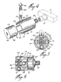
- a lock arrangement illustrated generally at 1, is mounted on a door 3 and includes an inner door knob/handle (hereinafter referred to as knob 5), having a centrally located push-button 7, and a push-button lock 9 having an outer door knob 11.
- the latch 13 extends through an edge of the door 3.
- the push-button lock 9 comprises a chamber 15 having a shaft 17 extending therethrough and out both sides of the chamber.
- a U-shaped latch retractor 25 Disposed within a casing 23, which is mounted in the door, between the front and rear sides of the door, is a U-shaped latch retractor 25 which is better illustrated in Figure 7. Disposed between the legs of the U-shaped latch retractor is a U-shaped member 27 having legs 128 and sides 127 (see Figure 7A) whose function will be discussed below.
- the U-shaped member 27 is biassed outwardly (towards the latch) by spring 28.
- Springs 30 bias the latch retracting member outwardly (towards the latch edge of the door).
- the inner end of the latch is disposed between the legs of the latch retractor 25 so that, when the latch retractor 25 is retracted inwardly (away from the latch edge of the door) against the force of springs 30, latch 13 is retracted so that the door can be open.
- spring 28 will force U-shaped member 27 outwardly (towards the latch edge of the door).
- lock rod 29 which extends through lock rod cylinder 31.
- lock rod cylinder 31 extends coaxially with the inside door knob from the inside door knob through one side of the inside door knob and into the door, and the lock rod cylinder 31 is rotatable with the door knob.
- Push-button 7 extends coaxially with the door knob from cylinder 31 and out of the cylinder and through the other side of the door knob. The push-button is rotatable with the cylinder.
- lock rod cylinder 31 has ears 32 at the inner edge thereof.
- the lock rod cylinder is also referred to as a drive cylinder, in this specific case, as an inside drive cylinder.
- Push-button 7 is biassed outwardly, through the other side of the inside door knob, by spring 33, Lock rod 29 is connected to push-button 7 and knob 5, so that cylinder 29, push-button 7 and lock rod 29 all rotate together.
- lock rod 29 includes openings 35.
- the push-button, and therefore the lock rod is pushed inwardly, the sides 127 (see Figure 7A) of U-shaped member 27 fall into the openings 35 and are maintained there by force of spring 28. Accordingly, the push-button will remain locked in its inward position.
- the sides 127 of U-shaped member 27 will no longer be disposed in the openings 35 so that, the push-button will be released with the inside knob rotated, and the push-button 7 will move outwardly once again, by force of spring 33, to the position illustrated in Figure 2.
- shaft 17 of the chamber 15 is connected, on the right-hand side thereof, through a connector 40, to an outside drive arrangement 34.
- the items numbered 21, 19, 15 and 40 comprise an outside door knob drive means for driving the outside drive arrangement.
- the outside drive arrangement 34 comprises a drive member having an ear 36 and a cylindrical shaft 38.
- the connector 40 is adaptable to different door thicknesses by changing the effective length thereof. When mounted in a relatively thin door, its shaft 140 is on the right-hand side (as in Figure 2). When mounted in a thicker door, its shaft 140 is on the left-hand side (as in Figure 2B), thus increasing the effective length of the arrangement by the length of the shaft.
- shaft 17 is rotatable so that, when outside door knob 11 is rotated, the rotation force will be transmitted from the shaft 21 through the clutch 19 to shaft 17 to connector 40 and thereby to outside drive arrangement 34.
- the drive member 36 will engage steps 26 of latch retractor 25 to thereby, once again, retract the latch retractor which, in turn, retracts the latch so that, once again, the door is open.
- the clutch 19 comprises a hollow outer cylindrical drive member 37 and a solid inner cylindrical driven core 39.
- the hollow outer cylindrical member 37 comprises four slits 41, 43, 45 and 47 which extend longitudinally of the cylindrical member 37 and which are spaced 90 degrees apart around the periphery of the cylindrical member 37.
- Each of the slots 41, 43, 45 and 47 is of the same width and length.
- one of the slots includes an expanded opening 42 adjacent the open end of the cylindrical member 37.
- This expanded opening 42 will be discussed below.
- the core member 39 includes circular openings 51 and 53 which extend diametrically through the core member 39.
- the direction of the circular opening 51 is transverse to the direction of the circular opening 53, and the opening 51 is at one position of the core member 39 while the opening 53 is at a second position of core member 39.
- the clutch also includes ball bearings 55 and 57, spaced apart by spring 59, and ball bearings 61 and 63, spaced apart by spring 65.
- ball bearings 55 and 57 with intermediate spring 59 are disposed at opening 53 whereas ball bearings 61 and 63, with intermediate spring 65, are disposed in opening 51.
- Shaft 17 would be inserted into opening 60 at the outer end of the inner core member 39.
- the inner core member, with the ball bearings and the springs inserted, would be inserted into the outer cylinder 37 until the inner end of the inner core member 39 abuts the inner wall of the outer cylindrical member 37.
- the ball bearings extend partially into one of the slots 41, 43, 45 or 47. As will be quite clear, the width of each slot must be less than the diameter of the ball bearings. The diameter of the ball bearings will, of course, all be the same size.
- the inner core member 39 In assembling with the opening 42, the inner core member 39 would be rotated so that it is aligned with the opening 42, and the inner core member would then be inserted into the cylinder so that opening 53 underlies the opening 42. Ball bearing 55 would then be dropped through the opening 42 into the opening 53, spring 59 would then be inserted after which ball bearing 57 would be inserted. Ball bearing 57 is then pressed down somewhat and the inner core member 39 is pushed inwardly and rotated through 90 degrees. The inner core member continues to be pushed inwardly until opening 51 underlies opening 42.
- Ball bearings 61 and 63 and spring 65 are inserted into opening 51 as above, and the ball bearing 63 is then pushed down and the inner core member 39 is pushed inwardly until its inner edge abuts the inner wall of the outer cylindrical member 37. As can be seen, the assembly has been made simpler and is susceptable to automation.
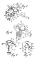
- FIG. 7 A first embodiment of a lock-out system is illustrated in association with Figures 7, 8, 9 and 10. These Figures illustrate the modifications which would be made to a cylindrical lock, for example, of the kind illustrated in Figures 1 and 2, in order to implement the lock-out system of the first embodiment.
- the U-shaped latch retractor 25 is modified by including thereon a stud 69 on the inside door side of the latch retractor.
- the locking rod, referenced in Figures 7 to 10 at 29′, is modified by including thereon an L-shaped member 71.
- the modified lock rod 29′ would extend through the lock rod cylinder 31 in the same way as lock rod 29 does in Figure 2.
- the U-shaped latch retractor 25 would be encased in the casing 23 in the same way as it is in Figure 2.
- Figure 2 illustrates the environment of the inventive lock-out system
- Figures 7 to 10 illustrate the specific details thereof.
- lock rod 29′ moves leftwardly in the direction of the arrow A in Figure 7. It will then assume the position illustrated in solid lines in Figures 8 and 9, i.e., the leg of the L-shaped member will be disposed behind the stud 69. Once again, the lock rod will be locked into its pushed-in position when the legs of the U-shaped member 27 fall into the openings 35 of the lock rod.
- lock rod 29′ will also rotate, in the direction of arrow B of Figure 8, so that the leg of the L-shaped member will move out of the way of the stud 69, and U-shaped latch retractor 25 will be retracted in the direction of arrow C of Figure 8. Accordingly, the door can be opened from the inside. At the same time, lock rod 29′ will be released so that the push-button will move outwardly due to the action of spring 33 as above-described.
- FIG. 11 A second embodiment of a lock rod system in accordance with the invention is illustrated in Figures 11, 12 and 13.
- the inside door arrangement is the same as in Figure 2.
- the outside drive arrangement 34 of Figure 2 is replaced with the outside sleeve drive 79 illustrated in Figures 11, 12 and 13.
- the outside sleeve drive 80 includes an ear 81 and slots 83.
- a lock-out cam 85 Attached to shaft 17, through opening 18, is a lock-out cam 85 having prongs 87 and biassed inwardly by spring 88.
- the lock rod 29 is modified by including at the free end thereof a freely rotating cup ring 89.
- the cup ring 89 abuts the lock-out cam 85 as seen in Figure 11.
- push-button 7 rotates with inside door knob 5
- lock rod 29 rotates with push-button 7, so that lock-out rod 29 rotates with inside door knob 5.
- Lock-out cam 85 rotates with shaft 17, and prongs 87 of lock-out cam 85 extend into slot 83 when the push-button is not pushed in as seen in Figure 11. Accordingly, when the correct combination has been inserted into the chamber 15 of permutation lock 9, and when outside door knob 11 is rotated, lock-out cam 85 will also rotate to rotate, in turn, outside sleeve drive 79. Ear 81 will engage either one of the steps 26 to retract U-shaped latch retractor 25 so that the door will be open.
- FIG. 1 A cover arrangement for a lock or the like in accordance with the invention is illustrated in Figures 1 and 3.
- the cover arrangement comprises a cover member 8 having indents 99 at the top end thereof. Preferably, there are two such indents equally spaced from the side edges of the cover member.
- the cover member also has a bottom opening 101. Different shapes for the opening are shown in Figures 3A and 3B. Obviously, other shapes could also be used.
- the cover arrangement also includes a door mounted plate 103 which has openings 105 which are aligned with the indents 99.
- a spring 107 is mounted on the plate 103 and is adapted to extend from the plate member and outwardly of the cover member 8 through the opening 101 thereof.
- the cover member is placed over the plate top end first so that the indents 99 extend into the openings 105.
- the bottom end is then pivoted so that the spring 107 extends out through the opening 101. (It will of course be appreciated that the cover member is mounted on the plate before the inside door knob 5 is mounted.)
- the force of the spring will maintain the cover arrangement closed against removal by application of a small force which might be applied, for example, by a child. However, applying enough force to overcome the holding power of the spring, which could easily be applied by an adult, will serve to remove the cover member from the plate.
Abstract
Description
- The present invention relates to improvements in cylindrical lock arrangements. The invention also relates to improvements in permutation lock arrangements.
- Some of the uses of such cylindrical lock arrangements provide privacy lock-out systems. With a cylindrical lock arrangement, this can be provided by a mechanism which is activated by a push-button on the inside door knob as will be further described below. The present application is partially directed at novel lock-out systems.
- With permutation lock arrangements, of the type as described for example in U.S. Patent 3,040,056, Rosenhagen, June 26, 1962, the shaft of the outside door knob is connected to the shaft of the permutation lock chamber. The shaft of the chamber will rotate, thereby permitting rotation of the outside door knob, only when the correct combination of the permutation lock has been punched in. Often, when the incorrect combination is inserted, so that the knob will not rotate, the user will apply excess force to the outside door knob to force the chamber shaft to rotate. This can cause damage to the chamber. It would therefore be desirable to provide means for permitting the outside door knob to rotate, under such conditions, without transmitting the rotating force to the chamber shaft.
- With permutation locks, it becomes necessary, from time to time, to change the combination. It would therefore be desirable to provide a cover which is easily removable by an adult, but which would present difficulty for a child to remove.
- It is therefore an object of the invention to provide novel lock-out systems for cylinder locks.
- It is a further object of the invention to provide clutch means between a door knob shaft and the shaft of a chamber of a permutation lock which permits rotation of the chamber shaft with the door knob shaft when the chamber shaft is not held against rotation, and which permits rotation of the door knob shaft, without the chamber shaft, when the chamber shaft is held against rotation.
- It is a still further object of the invention to provide an improved clutch means.
- It is a still further object of the invention to provide an easily removable cover arrangement for locks or the like.
- The invention will be better understood by an examination of the following description, together with the accompanying drawings, in which:
- FIGURE 1 is a perspective view of an arrangement in which all of the above described inventive features may be incorporated;
- FIGURE 2 is a cross-section through II-II of Figure 1;
- FIGURE 2A is a perspective view of the lock rod cylinder of Figure 2;
- FIGURE 2B is a view similar to Figure 2 showing the connector reversed;
- FIGURE 2C is a perspective exploded view of the connector and the outside drive arrangement of Figure 2;
- FIGURE 3 is a cross-section to illustrate the cover arrangement;
- FIGURES 3A and 3B illustrate two different types of openings for the cover arrangement;
- FIGURES 4, 5 and 6 illustrate the clutch of Figure 2;
- FIGURES 7, 8, 9 and 10 illustrate one embodiment of a lock-out system in accordance with the invention;
- FIGURE 7A is a perspective view of the U-shaped member; and
- FIGURES 11, 12 and 13 illustrate a second embodiment of a lock-out system in accordance with the invention.
- Turning now to Figure 1, a lock arrangement, illustrated generally at 1, is mounted on a
door 3 and includes an inner door knob/handle (hereinafter referred to as knob 5), having a centrally located push-button 7, and a push-button lock 9 having an outer door knob 11. Thelatch 13 extends through an edge of thedoor 3. - Turning to Figure 2, the push-button lock 9 comprises a
chamber 15 having ashaft 17 extending therethrough and out both sides of the chamber. Aclutch 19, which will be more fully described below, connects theshaft 17 to theshaft 21 of outer door knob 11. - Disposed within a
casing 23, which is mounted in the door, between the front and rear sides of the door, is aU-shaped latch retractor 25 which is better illustrated in Figure 7. Disposed between the legs of the U-shaped latch retractor is aU-shaped member 27 havinglegs 128 and sides 127 (see Figure 7A) whose function will be discussed below. - The U-shaped
member 27 is biassed outwardly (towards the latch) byspring 28. Springs 30 (see Figure 7), bias the latch retracting member outwardly (towards the latch edge of the door). - As is well known in the art, the inner end of the latch is disposed between the legs of the
latch retractor 25 so that, when thelatch retractor 25 is retracted inwardly (away from the latch edge of the door) against the force ofsprings 30,latch 13 is retracted so that the door can be open. When thelatch retractor 25 is retracted,spring 28 will force U-shapedmember 27 outwardly (towards the latch edge of the door). - When the
latch retractor 25 is in its normal position (not retracted), U-shapedmember 27 is maintained in its position abutting the inner side of the U-shaped latch retractor bylock rod 29 which extends throughlock rod cylinder 31. As can be seen,lock rod cylinder 31 extends coaxially with the inside door knob from the inside door knob through one side of the inside door knob and into the door, and thelock rod cylinder 31 is rotatable with the door knob. Push-button 7 extends coaxially with the door knob fromcylinder 31 and out of the cylinder and through the other side of the door knob. The push-button is rotatable with the cylinder. - As seen in Figure 2A,
lock rod cylinder 31 has ears 32 at the inner edge thereof. When theinside door knob 5, and thereby thecylinder 29, is rotated, one of the ears 32 will engage one of thesteps 26 of the U-shaped latch retractor and thereby cause the latch retractor to be retracted inwardly. Because there are two ears 32, the latch retractor will be retracted regardless of which direction theinside knob 5 is rotated. Because of this function of the cylinder, the lock rod cylinder is also referred to as a drive cylinder, in this specific case, as an inside drive cylinder. - Push-
button 7 is biassed outwardly, through the other side of the inside door knob, byspring 33,Lock rod 29 is connected to push-button 7 andknob 5, so thatcylinder 29, push-button 7 andlock rod 29 all rotate together. - As seen in Figure 2,
lock rod 29 includesopenings 35. When the push-button, and therefore the lock rod, is pushed inwardly, the sides 127 (see Figure 7A) of U-shapedmember 27 fall into theopenings 35 and are maintained there by force ofspring 28. Accordingly, the push-button will remain locked in its inward position. When theinside door knob 5 is rotated, thesides 127 of U-shapedmember 27 will no longer be disposed in theopenings 35 so that, the push-button will be released with the inside knob rotated, and the push-button 7 will move outwardly once again, by force ofspring 33, to the position illustrated in Figure 2. - As also seen in Figure 2,
shaft 17 of thechamber 15 is connected, on the right-hand side thereof, through aconnector 40, to anoutside drive arrangement 34. Thus, the items numbered 21, 19, 15 and 40 comprise an outside door knob drive means for driving the outside drive arrangement. As seen in Figures 2B and 2C, theoutside drive arrangement 34 comprises a drive member having anear 36 and acylindrical shaft 38. Theconnector 40 is adaptable to different door thicknesses by changing the effective length thereof. When mounted in a relatively thin door, itsshaft 140 is on the right-hand side (as in Figure 2). When mounted in a thicker door, itsshaft 140 is on the left-hand side (as in Figure 2B), thus increasing the effective length of the arrangement by the length of the shaft. - When
chamber 15 is in its unlock position (i.e., the correct combination has been inserted),shaft 17 is rotatable so that, when outside door knob 11 is rotated, the rotation force will be transmitted from theshaft 21 through theclutch 19 toshaft 17 toconnector 40 and thereby tooutside drive arrangement 34. Referring to Figure 7, when theoutside drive arrangement 34 is rotated, thedrive member 36 will engagesteps 26 oflatch retractor 25 to thereby, once again, retract the latch retractor which, in turn, retracts the latch so that, once again, the door is open. - If, on the other hand, the
chamber 15 is in its lock condition (the correct combination has not been inserted or the incorrect combination has been entered), thenshaft 17 will not be rotatable. Under this condition, when outside door knob 11 is rotated, andshaft 21 is rotated therewith,clutch 19 will slip so that the outside door knob will rotate without rotation of theshaft 17. - Referring now to Figures 4, 5 and 6, it can be seen that the
clutch 19 comprises a hollow outer cylindrical drive member 37 and a solid inner cylindrical drivencore 39. The hollow outer cylindrical member 37 comprises fourslits slots - In accordance with an improvement, one of the slots (e.g. slot 41) includes an expanded
opening 42 adjacent the open end of the cylindrical member 37. The purpose of this expandedopening 42 will be discussed below. - The
core member 39 includescircular openings core member 39. The direction of thecircular opening 51 is transverse to the direction of thecircular opening 53, and theopening 51 is at one position of thecore member 39 while theopening 53 is at a second position ofcore member 39. - The clutch also includes
ball bearings spring 59, andball bearings spring 65. As can be seen,ball bearings intermediate spring 59 are disposed at opening 53 whereasball bearings intermediate spring 65, are disposed inopening 51.Shaft 17 would be inserted into opening 60 at the outer end of theinner core member 39. The inner core member, with the ball bearings and the springs inserted, would be inserted into the outer cylinder 37 until the inner end of theinner core member 39 abuts the inner wall of the outer cylindrical member 37. The ball bearings extend partially into one of theslots - In order to assemble a clutch which does not include the
opening 42, the ball bearings and springs are inserted into theirrespective openings inner core member 39 while the inner core member is inserted into the outer cylindrical member 37. This is a rather difficult procedure and not very easy to automate. - With the expanded
opening 42, which would be greater than the diameter of the ball bearings, the assembly is made much simpler. - In assembling with the
opening 42, theinner core member 39 would be rotated so that it is aligned with theopening 42, and the inner core member would then be inserted into the cylinder so that opening 53 underlies theopening 42.Ball bearing 55 would then be dropped through theopening 42 into theopening 53,spring 59 would then be inserted after whichball bearing 57 would be inserted.Ball bearing 57 is then pressed down somewhat and theinner core member 39 is pushed inwardly and rotated through 90 degrees. The inner core member continues to be pushed inwardly until opening 51 underlies opening 42.Ball bearings spring 65 are inserted into opening 51 as above, and theball bearing 63 is then pushed down and theinner core member 39 is pushed inwardly until its inner edge abuts the inner wall of the outer cylindrical member 37. As can be seen, the assembly has been made simpler and is susceptable to automation. - In the operation of the clutch member, as the ball bearings extend into the slots, the
inner core member 39 will have the tendency to rotate with the outer cylindrical member 37. When shaft 17 (which extends into opening 60) is free to rotate, and whenshaft 67 is rotated, theinner core member 39 will rotate with the outer cylindrical member 37 so thatshaft 17 will rotate withshaft 67. However, whenshaft 17 is held against rotation (when the wrong combination has been entered or push-button 7 has been depressed for lock-out), and a rotating force is applied toshaft 67, outer cylindrical member 37 will tend to rotate whileinner core member 39 will be held against rotation. The rotation force of the outer cylindrical member 37 will forceball bearings spring 59, and will forceball bearings spring 65 so that the outer cylindrical member 37 alone will rotate, i.e., the clutch will slip. Thus, returning to Figure 2, outer door knob 11, and thereforeshaft 21, will rotate without transmitting the rotation force toshaft 17 and tooutside drive arrangement 34. Thus, the knob will rotate, but the door will not open. - A first embodiment of a lock-out system is illustrated in association with Figures 7, 8, 9 and 10. These Figures illustrate the modifications which would be made to a cylindrical lock, for example, of the kind illustrated in Figures 1 and 2, in order to implement the lock-out system of the first embodiment.
- In accordance with the invention, the
U-shaped latch retractor 25 is modified by including thereon astud 69 on the inside door side of the latch retractor. The locking rod, referenced in Figures 7 to 10 at 29′, is modified by including thereon an L-shapedmember 71. The modifiedlock rod 29′ would extend through thelock rod cylinder 31 in the same way aslock rod 29 does in Figure 2. Additionally, theU-shaped latch retractor 25 would be encased in thecasing 23 in the same way as it is in Figure 2. Thus, Figure 2 illustrates the environment of the inventive lock-out system, while Figures 7 to 10 illustrate the specific details thereof. - In operation, when push-
button 7 is pushed in,lock rod 29′ moves leftwardly in the direction of the arrow A in Figure 7. It will then assume the position illustrated in solid lines in Figures 8 and 9, i.e., the leg of the L-shaped member will be disposed behind thestud 69. Once again, the lock rod will be locked into its pushed-in position when the legs of theU-shaped member 27 fall into theopenings 35 of the lock rod. - When the outside door knob is now rotated, and drive
member 36 attempts to retract theU-shaped latch retractor 25 in the direction of arrow C, such retractive motion will be prevented because the motion of thestud 69 is blocked by the leg of the L-shapedmember 71. This again will force clutch 19 to slip. Accordingly, the door cannot be opened from the outside. - If, on the other hand, inside
door knob 5 is rotated in the direction of arrow B,lock rod 29′ will also rotate, in the direction of arrow B of Figure 8, so that the leg of the L-shaped member will move out of the way of thestud 69, andU-shaped latch retractor 25 will be retracted in the direction of arrow C of Figure 8. Accordingly, the door can be opened from the inside. At the same time,lock rod 29′ will be released so that the push-button will move outwardly due to the action ofspring 33 as above-described. - A second embodiment of a lock rod system in accordance with the invention is illustrated in Figures 11, 12 and 13. In this embodiment the inside door arrangement is the same as in Figure 2.
- The
outside drive arrangement 34 of Figure 2 is replaced with theoutside sleeve drive 79 illustrated in Figures 11, 12 and 13. The outside sleeve drive 80 includes anear 81 andslots 83. - Attached to
shaft 17, throughopening 18, is a lock-out cam 85 havingprongs 87 and biassed inwardly byspring 88. - The
lock rod 29 is modified by including at the free end thereof a freely rotatingcup ring 89. Thecup ring 89 abuts the lock-out cam 85 as seen in Figure 11. - Once again, push-
button 7 rotates withinside door knob 5, and lockrod 29 rotates with push-button 7, so that lock-outrod 29 rotates withinside door knob 5. - Lock-out
cam 85 rotates withshaft 17, and prongs 87 of lock-out cam 85 extend intoslot 83 when the push-button is not pushed in as seen in Figure 11. Accordingly, when the correct combination has been inserted into thechamber 15 of permutation lock 9, and when outside door knob 11 is rotated, lock-out cam 85 will also rotate to rotate, in turn,outside sleeve drive 79.Ear 81 will engage either one of thesteps 26 to retractU-shaped latch retractor 25 so that the door will be open. - When push-
button 7 is pushed in, as shown in Figure 13,cup ring 89 pushes lock-out cam leftwardly so thatprongs 87 are no longer inslot 83. Accordingly, there is no longer any connection between the outside door knob 11 and theoutside sleeve drive 79. Thus, when outside door knob 11 is rotated under the above conditions, although the door knob will rotate, the U-shaped latch retractor will not be retracted and the door will not open. Thus, the door cannot be opened from the outside under these conditions even when the correct combination has been inserted into the permutation lock. - A cover arrangement for a lock or the like in accordance with the invention is illustrated in Figures 1 and 3. Referring to these Figures, the cover arrangement comprises a
cover member 8 havingindents 99 at the top end thereof. Preferably, there are two such indents equally spaced from the side edges of the cover member. The cover member also has abottom opening 101. Different shapes for the opening are shown in Figures 3A and 3B. Obviously, other shapes could also be used. - Referring to Figure 3, the cover arrangement also includes a door mounted
plate 103 which hasopenings 105 which are aligned with theindents 99. Aspring 107 is mounted on theplate 103 and is adapted to extend from the plate member and outwardly of thecover member 8 through theopening 101 thereof. - In operation, the cover member is placed over the plate top end first so that the
indents 99 extend into theopenings 105. The bottom end is then pivoted so that thespring 107 extends out through theopening 101. (It will of course be appreciated that the cover member is mounted on the plate before theinside door knob 5 is mounted.) - The force of the spring will maintain the cover arrangement closed against removal by application of a small force which might be applied, for example, by a child. However, applying enough force to overcome the holding power of the spring, which could easily be applied by an adult, will serve to remove the cover member from the plate.
- Although several embodiments have been described, this was for the purpose of illustrating, but not limiting, the invention. Various modifications, which will come readily to the mind of one skilled in the art, are within the scope of the invention as defined in the appended claims.
Claims (17)
said arrangement comprising:
an inside door knob/handle mountable on the inside of said door in alignment with said latch;
an outside door knob/handle mountable on the outside of said door in alignment with said inside door knob/handle;
a lock rod cylinder extending coaxially with said inside door knob/handle from said inside door knob/handle through one side of said inside door knob/handle into said door and rotatable with said inside door knob/handle;
a push-button extending coaxially with said inside door knob/handle from said drive cylinder and out of said cylinder and through the other side of said inside door knob/handle, said push-button being rotatable with said inside door knob/handle;
means for locking said push-button into a pushed-in position when the push-button is pushed inwardly, and for releasing it from its pushed-in position when said inside door knob/handle is rotated;
a lock rod extending coaxially with said drive cylinder from said push-button through said drive cylinder through said one side of said door and into said door, said lock rod being rotatable with said push-button and thereby with said inside door knob/handle;
latch retractor means mounted in said door in alignment with said latch;
means associated with said lock rod cylinder for retracting said latch retractor means, to thereby retract said latch, when said inside door knob/handle is rotated;
said outside door knob/handle having an outside drive means extending into said door coaxially with, and in alignment with said lock rod cylinder;
an outside drive arrangement connected to said outside door drive means and rotatable therewith, and thereby with said outside door knob/handle, and including means for retracting said latch retractor means, and thereby said latch, when said outside door knob/handle, and thereby said outside drive arrangement, is rotated;
and including a lock-out system comprising:
a stud mounted on said latch retractor means on the side thereof adjacent said inside door knob/handle;
an L-shaped member on said lock rod having a leg which extends behind said stud when said push-button, and therefore said lock rod, is pushed inwardly, thereby preventing retraction of said latch retractor means;
whereby, when said push-button is pushed-in, retraction of said latch retraction means will be prevented when it is attempted to rotate said outside door knob/handle, but, when said inside door knob/handle is once rotated, said lock rod is rotated and pushed outwardly so that the leg is no longer behind said stud whereby said latch retraction means will be retracted.
and wherein said means for locking said push-button into a pushed-in position comprises:
a U-shaped member having two long legs joined by a bridge;
two short legs descending from said bridge on either side thereof and transverse to said long legs;
said U-shaped member being disposed in said U-shaped cavity such that the long legs thereof are aligned with the legs of the U-shaped cavity;
said lock rod including openings which engage said short legs when said push-button is pushed-in, whereby to lock said push-button into the pushed-in position; and
spring means biassing said push-button out of the pushed-in position;
whereby, when said inside door knob/handle is rotated to thereby rotate said lock rod so that said openings of said lock-out rod disengage from said short legs, said spring means pushes said push-button out of said pushed-in position.
and wherein said means associated with said lock rod cylinder for retracting said latch retractor means comprises:
two ears extending transversely of said lock rod cylinder at the inner end thereof, said ears being so disposed that, when said inside door knob/handle is rotated, to thereby rotate said lock rod cylinder, a respective one of said ears engages a respective one of said steps of said inner side wall to retract said latch retractor means;
whereby, to retract said latch upon rotation of said inside door knob/handle.
said outside drive arrangement comprising a cylindrical shaft, connected to said outside door drive means by a cylindrical shaft connecting means, and a wide ear extending transversely of said cylindrical shaft at the inner end thereof;
said wide ear being so disposed that, when said outside door knob/handle is rotated, to thereby rotate said outside door drive means and said cylindrical shaft, a respective edge of said wide ear engages a respective one of said steps of said outer side wall;
whereby, to retract said latch upon rotation of said inside door knob/handle.
and wherein said cylindrical shaft connecting means has a first member of a first length having a cross-sectional shape corresponding with the shape of said opening in the back wall of said cylindrical shaft, and a second member of a second length integrally connected with said first member and connected to said shaft of said outside door knob/handle;
whereby, when said first member of said cylindrical shaft connecting means is inserted into said opening of said back wall of said cylindrical shaft, said cylindrical shaft will rotate with said shaft of said outside door knob/handle;
wherein, when said cylindrical shaft connecting means is inserted into said opening of said cylindrical shaft with said first member facing said inside door knob/handle and said second member facing said outside door knob/handle, the spacing of said cylindrical shaft connecting means is determined by said first length and said second length; and
when said cylindrical shaft connecting means is inserted into said opening of said cylindrical shaft with said first member facing said outside door knob/handle and said second member facing said inside door knob/handle, the spacing of said cylindrical shaft connecting means is determined by only said first length.
said arrangement comprising:
an inside door knob/handle mountable on the inside of said door in alignment with said latch;
an outside door knob/handle mountable on the outside of said door in alignment with said inside door knob/handle;
a lock rod cylinder extending coaxially with said inside door knob/handle from said inside door knob/handle through one side of said inside door knob/handle into said door and rotatable with said inside door knob/handle;
a push-button extending coaxially with said door knob/handle from said drive cylinder and out of said cylinder and through the other side of said door knob/handle, said push-button being rotatable with said door knob/handle;
means for locking said push-button into a pushed-in position when the push-button is pushed inwardly, and for releasing it from its pushed-in position when said inside door knob/handle is rotated;
a lock rod extending coaxially with said drive cylinder from said push-button through said drive cylinder through said one side of said door and into said door, said lock rod being rotatable with said push-button and thereby with said inside door knob/handle;
latch retractor means mounted in said door in alignment with said latch;
means associated with said lock rod cylinder for retracting said latch retractor means, to thereby retract said latch, when said inside door knob/handle is rotated'
said outside door knob/handle having a shaft extending into said door coaxially with, and in alignment with said lock rod cylinder;
an outside drive arrangement connected to said outside door driven means and rotatable therewith, and thereby with said outside door knob/handle, and including means for retracting said latch retractor means, and thereby said latch, when said outside door knob/handle, and thereby said outside drive arrangement, is rotated;
said outside drive arrangement comprising a cylindrical shaft, connected to said outside door drive means by a cylindrical shaft connecting means, and a wide ear extending transversely of said cylindrical shaft at the inner end thereof;
and including a lock-out system comprising:
means associated with said lock rod for disconnecting said outside drive arrangement from said cylindrical shaft when said push-button is pushed in;
whereby, when said push-button is pushed in, rotation of said outside door knob/handle will not cause rotation of said outside drive arrangement so that said latch retractor means will not be retracted, but, rotation of said inside door knob/handle will cause retraction of said latch retractor means.
and wherein said means for locking said push-button into a pushed-in position comprises:
a U-shaped member having two long legs joined by a bridge;
two short legs descending from said bridge on either side thereof and transverse to said long legs;
said U-shaped member being disposed in said U-shaped cavity such that the long legs thereof are aligned with the legs of the U-shaped cavity;
said lock rod including openings which engage said short legs when said push-button is pushed-in, whereby to lock said push-button into the pushed-in position; and
spring means biassing said push-button out of the pushed-in position;
whereby, when said inside door knob/handle is rotated to thereby rotate said lock rod so that said openings of said lock-out rod disengage from said short legs, said spring means pushes said push-button out of said pushed-in position.
and wherein said means associated with said lock rod cylinder for retracting said latch retractor means comprises:
two ears extending transversely of said lock rod cylinder at the inner end thereof, said ears being so disposed that, when said inside door knob/handle is rotated, to thereby rotate said lock rod cylinder, a respective one of said ears engages a respective one of said steps of said inner side wall to retract said latch retractor means;
whereby, to retract said latch upon rotation of said inside door knob/handle.
said wide ear being so disposed that, when said outside door knob/handle is rotated, to thereby rotate said outisde door drive means and said cylindrical shaft, a respective edge of said wide ear engages a respective one of said steps of said outer side wall.
said cylindrical shaft connecting means comprising a lock-out cam comprising a cylindrical member having prongs at the inner end thereof for engagement in respective ones of said slots of said cylindrical shaft, and means in said lock-out cam for connecting said lock-out cam to said outside door knob/handle shaft, and lock-out cam spring means biassing said lock-out cam towards said cylindrical shaft so that said prongs engage in said slots, whereby said cylindrical shaft is rotatable with said outside door knob/handle shaft;
a rotating cup ring mounted at the inner end of said lock rod, said rotating cup ring abutting said lock-out cam;
whereby, when said push-button is pushed into said push-in position, said rotating cup ring pushes said lock-out cam away from said cylindrical shaft against the force of said lock-out cam spring means so that said prongs no longer engage in said slots;
whereby, said cylindrical shaft is not rotatable with said outer door knob/handle shaft.
a permutation lock chamber having a chamber shaft extending therethrough, said chamber shaft being held against rotation when the chamber is in a locked condition and said chamber shaft being rotatable when said chamber is in an unlocked condition;
an outer door knob/handle having an outer knob/handle shaft extending therefrom and rotatable therewith;
clutch means connecting said outer door knob/handle shaft and said chamber shaft;
whereby, when said chamber is in its unlock condition and said outer door knob/handle is rotated, said clutch engages and said chamber shaft rotates with said outer door knob/handle shaft; and
when said chamber is in its locked condition, said clutch slips to permit rotation of said outer door knob/handle shaft without rotation of said chamber shaft.
a hollow cylindrical member having a closed end and an open end, four slots of equal length and width extending from said open end and longitudinally of said cylindrical member and spaced 90o from each other around the periphery of said cylindrical member, said outer door knob/handle shaft being connectable at said closed end of said cylindrical member;
a solid cylindrical inner core member insertable into said hollow cylindrical member, from a first end thereof, and having a first opening extending diametrically through said core transverse to the longitudinal axis thereof at a first position of said core, and a second opening extending diametrically through said core transverse to both said first opening and the longitudinal axis of said core;
a first ball bearing at one end of said first opening and a second ball bearing at the other end of said first opening and a first spring between said first and second ball bearings urging said ball bearings away from each other towards said hollow cylindrical member;
a third ball bearing at one end of said second opening and a fourth ball bearing at the other end of said second opening and a second spring between said third and fourth ball bearings urging said third and fourth ball bearings away from each other towards said hollow cylindrical member;
the diameters of said ball bearings all being of equal size and being greater than the width of said slots; and
the second end of said solid cylindrical inner core member being connected to said chamber shaft.
said clutch comprising:
a hollow outer cylindrical member having a closed end and an open end, four slots, of equal length and width, extending from said open end and longitudinally of said cylindrical member and spaced 90 degrees from each other around the periphery of said cylindrical member, said first shaft being connectable at said closed end of said cylindrical member;
a solid cylindrical inner core member insertable into said hollow cylindrical member, from a first end thereof, and having a first opening extending diametrically through said core transverse to the longitudinal axis thereof at a first position of said core, and a second opening extending diametrically through said core transverse to both said first opening and the longitudinal axis of said core;
a first ball bearing at one end of said first opening and a second ball bearing at the other end of said first opening and a first spring between said first and second ball bearings urging said ball bearings away from each other towards said hollow cylindrical member;
a third ball bearing at one end of said second opening and a fourth ball bearing at the other end of said second opening and a second spring between said third and fourth ball bearings urging said third and fourth ball bearings away from each other towards said hollow cylindrical member;
the diameters of said ball bearings all being of equal size and being greater than the width of said slots;
an expanded opening at the end of one of said slots adjacent the open end of said hollow cylindrical member, said expanded opening being large enough to permit the passage of a ball bearing therethrough;
whereby to facilitate the loading of said ball bearings and springs during assembly of said clutch.
a mounting plate mountable on a surface and having a first end and a second end;
a cover member having a corresponding first end and second end and mountable on said mounting plate;
an outwardly bent rim at said first end of said mounting plate;
a first inwardly bent rim at said first end of said cover member and a second inwardly bent rim at said second end of said cover member;
at least one indent in said first inwardly bent rim of said cover member and a corresponding top opening in said outwardly bent rim of said mounting plate;
a bottom opening in said cover member adjacent the second end thereof;
spring means mounted on said mounting plate adjacent the second end thereof and extendable through said bottom opening when said cover member is mounted on said mounting plate;
whereby, when said cover member is mounted on said mounting plate it is held thereon by the force of said spring and can be dismounted by overcoming the force of said spring.
Applications Claiming Priority (2)
| Application Number | Priority Date | Filing Date | Title |
|---|---|---|---|
| CA566657 | 1988-05-12 | ||
| CA000566657A CA1308762C (en) | 1988-05-12 | 1988-05-12 | Cylindrical and permutation lock arrangements |
Publications (3)
| Publication Number | Publication Date |
|---|---|
| EP0341656A2 true EP0341656A2 (en) | 1989-11-15 |
| EP0341656A3 EP0341656A3 (en) | 1990-10-17 |
| EP0341656B1 EP0341656B1 (en) | 1993-09-22 |
Family
ID=4138018
Family Applications (1)
| Application Number | Title | Priority Date | Filing Date |
|---|---|---|---|
| EP89108316A Expired - Lifetime EP0341656B1 (en) | 1988-05-12 | 1989-05-09 | Cylindrical and permutation lock arrangements |
Country Status (5)
| Country | Link |
|---|---|
| US (1) | US5040652A (en) |
| EP (1) | EP0341656B1 (en) |
| JP (1) | JPH0249880A (en) |
| CA (1) | CA1308762C (en) |
| DE (1) | DE68909302T2 (en) |
Cited By (6)
| Publication number | Priority date | Publication date | Assignee | Title |
|---|---|---|---|---|
| EP0698705A1 (en) * | 1992-08-13 | 1996-02-28 | Emhart Inc. | Door lockset with spindle bearing |
| WO1998032938A1 (en) * | 1997-01-27 | 1998-07-30 | Schlage Lock Company | Door lock with clutching mechanism |
| EP1223270A2 (en) * | 2001-01-11 | 2002-07-17 | C. Ed. Schulte Gesellschaft mit beschränkter Haftung Zylinderschlossfabrik | Lock cylinder with slip-clutch coupling to a rotating knob handle |
| GB2528327A (en) * | 2014-07-18 | 2016-01-20 | Surelock Mcgill Ltd | Clutch and handle for lockable mechanism |
| US10202784B2 (en) | 2014-07-18 | 2019-02-12 | Surelock Mcgill Limited | Clutch and handle for lockable mechanism |
| US20220042346A1 (en) * | 2019-09-11 | 2022-02-10 | Carrier Corporation | Hub assembly for door handle |
Families Citing this family (55)
| Publication number | Priority date | Publication date | Assignee | Title |
|---|---|---|---|---|
| US5285667A (en) * | 1990-11-30 | 1994-02-15 | Alpha Corporation | Cylinder lock |
| US5121618A (en) * | 1991-07-25 | 1992-06-16 | Rita Scott | Attachment for transforming lock cylinders into interchangeable cores |
| DE4136271C1 (en) * | 1991-11-04 | 1993-03-11 | Gkn Automotive Ag, 5200 Siegburg, De | |
| US5150592A (en) * | 1991-12-02 | 1992-09-29 | Taiwan Fu Hsing Industry Co., Ltd. | Locking device for an auxiliary lock |
| US5226304A (en) * | 1991-12-30 | 1993-07-13 | Michael Scott | Universal cylinder modification kit enables lock to have interchangeable care |
| US5297405A (en) * | 1993-01-25 | 1994-03-29 | General Motors Corporation | Door handle assembly with snap-in key cylinder |
| US5295376A (en) * | 1993-04-22 | 1994-03-22 | Fort Lock Corporation | Zero clearance lock |
| US5428873A (en) * | 1993-04-29 | 1995-07-04 | Bw/Ip International, Inc. | Ball Latch mechanism |
| US5451070A (en) * | 1993-05-26 | 1995-09-19 | Lindsay; Stuart M. W. | Treadle drive system with positive engagement clutch |
| US5520427A (en) * | 1993-12-27 | 1996-05-28 | Von Duprin, Inc. | Breakaway lever with wedge release mechanism |
| US5516161A (en) * | 1993-12-27 | 1996-05-14 | Von Duprin, Inc. | Breakaway lever clutch with cam drive pin |
| US5794472A (en) * | 1995-05-01 | 1998-08-18 | Best Lock Corporation | Disconnecting drive mechanism for cylindrical lockset |
| KR970015988A (en) * | 1995-09-13 | 1997-04-28 | 박정우 | Lock body damage prevention device of cylindrical lever door lock |
| US5813261A (en) | 1996-10-31 | 1998-09-29 | Boehlow; Robert D. | Keyless deadbolt lock engaging device |
| US5617749A (en) * | 1996-05-30 | 1997-04-08 | Dusan Metals, Inc. | Door lock |
| US5787743A (en) * | 1996-11-18 | 1998-08-04 | Pdq Industries, Inc. | Torque limiting lock mechanism |
| US7007524B2 (en) * | 1997-02-10 | 2006-03-07 | Lockmasters, Inc. | Dead bolt lock system having multiple security features |
| US7424814B2 (en) * | 1997-02-10 | 2008-09-16 | Lockmasters, Inc. | Dead bolt lock system having multiple security features |
| US6622534B1 (en) * | 1997-02-10 | 2003-09-23 | Lockmasters, Inc. | Dead bolt system having multiple security features |
| US6000512A (en) * | 1997-07-30 | 1999-12-14 | Dana Corporation | Overrunning clutch with spring energized cage centering device |
| US5934117A (en) * | 1997-09-24 | 1999-08-10 | Shen; Mu-Lin | Lock with a clutching outer handle |
| US5904232A (en) * | 1997-09-25 | 1999-05-18 | Shen; Mu-Lin | Clutch assembly enabling a free turn of an outer handle of a door with respect to a latch assembly of a lock |
| US6595031B2 (en) * | 2000-12-19 | 2003-07-22 | Larry Stephen Wilson | Retaining device for personal vehicle with handlebars |
| US6527314B2 (en) | 2001-02-20 | 2003-03-04 | Jackson Corporation | Clutch handle |
| US6979354B2 (en) * | 2002-05-03 | 2005-12-27 | Wagman Manufacturing, Inc. | Prosthetic attachment locking device |
| TW539028U (en) * | 2002-07-29 | 2003-06-21 | Tong Lung Metal Ind Co Ltd | Clutch structure of locks |
| IL154193A0 (en) * | 2003-01-30 | 2003-07-31 | Goldtec Security Ltd | Door locking system |
| US8011217B2 (en) * | 2003-05-09 | 2011-09-06 | Simonsvoss Technologies Ag | Electronic access control handle set for a door lock |
| US20040255628A1 (en) * | 2003-05-09 | 2004-12-23 | Herbert Meyerle | Door lock system and method |
| DE10320873B4 (en) * | 2003-05-09 | 2006-02-09 | Simonsvoss Technologies Ag | Motion transmission device and method |
| US7845201B2 (en) * | 2003-05-09 | 2010-12-07 | Simonsvoss Technologies Ag | Electronic access control device |
| US8683833B2 (en) * | 2003-05-09 | 2014-04-01 | Simonsvoss Technologies Ag | Electronic access control handle set for a door lock |
| JP4100570B2 (en) * | 2003-10-03 | 2008-06-11 | 本田技研工業株式会社 | Vehicle locking device |
| US7389661B2 (en) * | 2004-09-24 | 2008-06-24 | Viviano Robert J | Keyless deadbolt door lock assembly |
| US7721660B1 (en) * | 2005-09-30 | 2010-05-25 | Diebold, Incorporated | Deal drawer |
| KR100818042B1 (en) | 2007-11-16 | 2008-03-31 | 민병도 | Safety operating device of door lock |
| CN201460433U (en) * | 2009-02-06 | 2010-05-12 | 闵瑜 | Clutch left-and-right interchanging device of lock |
| US8677792B2 (en) * | 2009-02-25 | 2014-03-25 | Adams Rite Manufacturing Co. | Electronic door lock apparatus |
| JP5499174B2 (en) * | 2009-09-21 | 2014-05-21 | マスター ロック カンパニー エルエルシー | Lockable enclosure |
| US8555686B2 (en) * | 2009-12-07 | 2013-10-15 | Master Lock Company Llc | Mechanical pushbutton locking arrangements |
| US8943864B2 (en) * | 2010-01-18 | 2015-02-03 | Liberty Safe And Security Products, Inc. | Proportional torque shaft clutch assembly |
| US8079241B2 (en) * | 2010-03-10 | 2011-12-20 | Thase Enterprise Co., Ltd. | Adjustable shaft for door lock assembly |
| CN201881326U (en) * | 2010-11-09 | 2011-06-29 | 徐雪峰 | Impact mechanism for electric tools |
| US9051761B2 (en) | 2011-08-02 | 2015-06-09 | Kwikset Corporation | Manually driven electronic deadbolt assembly with fixed turnpiece |
| EP2802719A4 (en) | 2012-01-11 | 2016-08-03 | Schlage Lock Co Llc | Safety mechanism for door handle |
| CN203361845U (en) | 2013-01-02 | 2013-12-25 | 莱诺金属公司 | Lock enclosure |
| WO2014151024A1 (en) | 2013-03-15 | 2014-09-25 | Kwikset Corporation | Electro-mechanical locks with bezel turning function |
| US10294702B1 (en) * | 2014-01-01 | 2019-05-21 | Brisbin Marvin Skiles | “Skiles locking system” S.L.S |
| US9995060B2 (en) | 2014-04-14 | 2018-06-12 | Lockmasters Technologies Inc. | Dead bolt lock system and method of retracting a dead bolt |
| US20210156434A1 (en) * | 2014-08-22 | 2021-05-27 | Re-Dai Precision Tools Co., Ltd. | Elastic short-pin type universal joint |
| JP2016108928A (en) * | 2014-12-02 | 2016-06-20 | Ntn株式会社 | Electric lock |
| WO2018160710A1 (en) * | 2017-03-01 | 2018-09-07 | Carrier Corporation | Pivoting magnet security latch |
| US10626634B2 (en) | 2018-02-02 | 2020-04-21 | Schlage Lock Company Llc | Anti-barricading turn hub assembly for a door lockset |
| US10612273B2 (en) | 2018-03-13 | 2020-04-07 | Schlage Lock Company Llc | Anti-barricading thumb turn assembly for a door lockset |
| US11377873B2 (en) * | 2019-03-12 | 2022-07-05 | Schlage Lock Company Llc | Electric latch mechanism |
Citations (2)
| Publication number | Priority date | Publication date | Assignee | Title |
|---|---|---|---|---|
| US2434288A (en) * | 1944-05-27 | 1948-01-13 | Schlage Lock Co | Door lock |
| US3022102A (en) * | 1959-06-29 | 1962-02-20 | Russell | Emergency release bar |
Family Cites Families (14)
| Publication number | Priority date | Publication date | Assignee | Title |
|---|---|---|---|---|
| GB191515816A (en) * | 1915-11-09 | 1916-02-03 | Bernard Gilbert | Improved Safety Clutch for Feed Gears of Machine Tools and the like. |
| US1611940A (en) * | 1924-02-01 | 1926-12-21 | Ohmer Fare Register Co | Yieldable driving mechanism |
| US1671521A (en) * | 1926-11-26 | 1928-05-29 | Mccrosky Tool Corp | Shaft coupling |
| US1899996A (en) * | 1931-07-08 | 1933-03-07 | Studebaker Corp | Doorlock handle |
| US1910125A (en) * | 1932-01-02 | 1933-05-23 | Carl H Root | Door handle |
| US2366841A (en) * | 1942-04-03 | 1945-01-09 | Adiel Y Dodge | Coupling |
| US2544809A (en) * | 1945-04-10 | 1951-03-13 | American Viscose Corp | Overload release clutch |
| US2885918A (en) * | 1954-12-24 | 1959-05-12 | Vertriebund Verkauf Ag | Predetermined torque release wrench |
| US3040556A (en) * | 1958-12-31 | 1962-06-26 | Simplex Lock Corp | Permutation lock |
| US4679420A (en) * | 1985-01-02 | 1987-07-14 | Yang Tai Her | Force immune door latch |
| US4786271A (en) * | 1985-11-01 | 1988-11-22 | Menn Pavel M | Coupling for end-to-end rotatable shafts |
| US4773240A (en) * | 1986-10-20 | 1988-09-27 | Best Lock Corporation | Lock with force-override assembly |
| US4854143A (en) * | 1987-08-07 | 1989-08-08 | Intelock Corporation | Bolt assembly and method |
| US4941697A (en) * | 1989-11-28 | 1990-07-17 | Caesar Fan | Over-loading idling lock set |
-
1988
- 1988-05-12 CA CA000566657A patent/CA1308762C/en not_active Expired - Lifetime
-
1989
- 1989-05-09 DE DE89108316T patent/DE68909302T2/en not_active Expired - Fee Related
- 1989-05-09 EP EP89108316A patent/EP0341656B1/en not_active Expired - Lifetime
- 1989-05-09 US US07/349,358 patent/US5040652A/en not_active Expired - Lifetime
- 1989-05-12 JP JP1120245A patent/JPH0249880A/en active Pending
Patent Citations (2)
| Publication number | Priority date | Publication date | Assignee | Title |
|---|---|---|---|---|
| US2434288A (en) * | 1944-05-27 | 1948-01-13 | Schlage Lock Co | Door lock |
| US3022102A (en) * | 1959-06-29 | 1962-02-20 | Russell | Emergency release bar |
Cited By (9)
| Publication number | Priority date | Publication date | Assignee | Title |
|---|---|---|---|---|
| EP0698705A1 (en) * | 1992-08-13 | 1996-02-28 | Emhart Inc. | Door lockset with spindle bearing |
| WO1998032938A1 (en) * | 1997-01-27 | 1998-07-30 | Schlage Lock Company | Door lock with clutching mechanism |
| US6189351B1 (en) * | 1997-01-27 | 2001-02-20 | Schlage Lock Company | Door lock with clutching mechanism |
| EP1223270A2 (en) * | 2001-01-11 | 2002-07-17 | C. Ed. Schulte Gesellschaft mit beschränkter Haftung Zylinderschlossfabrik | Lock cylinder with slip-clutch coupling to a rotating knob handle |
| EP1223270A3 (en) * | 2001-01-11 | 2003-11-26 | C. Ed. Schulte Gesellschaft mit beschränkter Haftung Zylinderschlossfabrik | Lock cylinder with slip-clutch coupling to a rotating knob handle |
| GB2528327A (en) * | 2014-07-18 | 2016-01-20 | Surelock Mcgill Ltd | Clutch and handle for lockable mechanism |
| US10202784B2 (en) | 2014-07-18 | 2019-02-12 | Surelock Mcgill Limited | Clutch and handle for lockable mechanism |
| GB2528327B (en) * | 2014-07-18 | 2020-12-16 | Surelock Mcgill Ltd | Clutch and handle for lockable mechanism |
| US20220042346A1 (en) * | 2019-09-11 | 2022-02-10 | Carrier Corporation | Hub assembly for door handle |
Also Published As
| Publication number | Publication date |
|---|---|
| EP0341656A3 (en) | 1990-10-17 |
| DE68909302T2 (en) | 1994-01-27 |
| DE68909302D1 (en) | 1993-10-28 |
| JPH0249880A (en) | 1990-02-20 |
| CA1308762C (en) | 1992-10-13 |
| US5040652A (en) | 1991-08-20 |
| EP0341656B1 (en) | 1993-09-22 |
Similar Documents
| Publication | Publication Date | Title |
|---|---|---|
| EP0341656A2 (en) | Cylindrical and permutation lock arrangements | |
| US4394821A (en) | Door lock mechanism | |
| US4920773A (en) | Door lock having disengages outer lever handle when in the locked condition and means to bias the handle toward horizontal position | |
| US6058751A (en) | Free-wheeling lock | |
| US4689976A (en) | Pop-up handle assembly | |
| US4048821A (en) | Combination padlock | |
| JPS6117154Y2 (en) | ||
| EP0659962A2 (en) | Cylinder lock resistible against breaking | |
| US4843852A (en) | Disposable construction core | |
| US6223567B1 (en) | Door lock with clutch arrangement | |
| GB2228523A (en) | A locking mechanism | |
| US3765199A (en) | Lock anti-pick device | |
| JPS58204277A (en) | Lock set for door panel | |
| US4428570A (en) | Tool-loadable biasing spring | |
| EP0472292A2 (en) | Push-button lock arrangement | |
| US6634197B2 (en) | Lock device with removable core | |
| US6116663A (en) | Casket Lock | |
| US5119650A (en) | Combination padlock with re-setting mechanism | |
| US5916281A (en) | Shuttling throw member for lockset | |
| US3995463A (en) | Key ejector lock | |
| US4927197A (en) | Spring-latch door lock provided with an improved locking system and adapted to be used for inwardly and outwardly opened doors | |
| EP1826339A1 (en) | Safety lock | |
| US4007615A (en) | Key controlled pick resistant lock | |
| CN210622525U (en) | Door lock | |
| JP2008540877A (en) | Lock with rotor fixing means |
Legal Events
| Date | Code | Title | Description |
|---|---|---|---|
| PUAI | Public reference made under article 153(3) epc to a published international application that has entered the european phase |
Free format text: ORIGINAL CODE: 0009012 |
|
| AK | Designated contracting states |
Kind code of ref document: A2 Designated state(s): BE DE FR GB IT LU NL |
|
| RAP1 | Party data changed (applicant data changed or rights of an application transferred) |
Owner name: ILCO UNICAN, INC. |
|
| PUAL | Search report despatched |
Free format text: ORIGINAL CODE: 0009013 |
|
| AK | Designated contracting states |
Kind code of ref document: A3 Designated state(s): BE DE FR GB IT LU NL |
|
| 17P | Request for examination filed |
Effective date: 19901231 |
|
| 17Q | First examination report despatched |
Effective date: 19920120 |
|
| GRAA | (expected) grant |
Free format text: ORIGINAL CODE: 0009210 |
|
| AK | Designated contracting states |
Kind code of ref document: B1 Designated state(s): BE DE FR GB IT LU NL |
|
| PG25 | Lapsed in a contracting state [announced via postgrant information from national office to epo] |
Ref country code: NL Effective date: 19930922 Ref country code: BE Effective date: 19930922 |
|
| REF | Corresponds to: |
Ref document number: 68909302 Country of ref document: DE Date of ref document: 19931028 |
|
| ITF | It: translation for a ep patent filed |
Owner name: ING. A. GIAMBROCONO & C |
|
| ET | Fr: translation filed | ||
| NLV1 | Nl: lapsed or annulled due to failure to fulfill the requirements of art. 29p and 29m of the patents act | ||
| PG25 | Lapsed in a contracting state [announced via postgrant information from national office to epo] |
Ref country code: LU Free format text: LAPSE BECAUSE OF NON-PAYMENT OF DUE FEES Effective date: 19940531 |
|
| PLBE | No opposition filed within time limit |
Free format text: ORIGINAL CODE: 0009261 |
|
| STAA | Information on the status of an ep patent application or granted ep patent |
Free format text: STATUS: NO OPPOSITION FILED WITHIN TIME LIMIT |
|
| 26N | No opposition filed | ||
| PGFP | Annual fee paid to national office [announced via postgrant information from national office to epo] |
Ref country code: FR Payment date: 19950530 Year of fee payment: 7 |
|
| PGFP | Annual fee paid to national office [announced via postgrant information from national office to epo] |
Ref country code: DE Payment date: 19950630 Year of fee payment: 7 |
|
| PG25 | Lapsed in a contracting state [announced via postgrant information from national office to epo] |
Ref country code: FR Effective date: 19970131 |
|
| PG25 | Lapsed in a contracting state [announced via postgrant information from national office to epo] |
Ref country code: DE Effective date: 19970201 |
|
| REG | Reference to a national code |
Ref country code: FR Ref legal event code: ST |
|
| PGFP | Annual fee paid to national office [announced via postgrant information from national office to epo] |
Ref country code: GB Payment date: 20000502 Year of fee payment: 12 |
|
| PG25 | Lapsed in a contracting state [announced via postgrant information from national office to epo] |
Ref country code: GB Free format text: LAPSE BECAUSE OF NON-PAYMENT OF DUE FEES Effective date: 20010509 |
|
| GBPC | Gb: european patent ceased through non-payment of renewal fee |
Effective date: 20010509 |
|
| PG25 | Lapsed in a contracting state [announced via postgrant information from national office to epo] |
Ref country code: IT Free format text: LAPSE BECAUSE OF NON-PAYMENT OF DUE FEES;WARNING: LAPSES OF ITALIAN PATENTS WITH EFFECTIVE DATE BEFORE 2007 MAY HAVE OCCURRED AT ANY TIME BEFORE 2007. THE CORRECT EFFECTIVE DATE MAY BE DIFFERENT FROM THE ONE RECORDED. Effective date: 20050509 |