EP0338866A2 - Method for downloading a scrambled television signal and receiver therefor - Google Patents
Method for downloading a scrambled television signal and receiver therefor Download PDFInfo
- Publication number
- EP0338866A2 EP0338866A2 EP89304038A EP89304038A EP0338866A2 EP 0338866 A2 EP0338866 A2 EP 0338866A2 EP 89304038 A EP89304038 A EP 89304038A EP 89304038 A EP89304038 A EP 89304038A EP 0338866 A2 EP0338866 A2 EP 0338866A2
- Authority
- EP
- European Patent Office
- Prior art keywords
- signal
- data code
- generating
- predetermined data
- control signals
- Prior art date
- Legal status (The legal status is an assumption and is not a legal conclusion. Google has not performed a legal analysis and makes no representation as to the accuracy of the status listed.)
- Withdrawn
Links
Images
Classifications
-
- H—ELECTRICITY
- H04—ELECTRIC COMMUNICATION TECHNIQUE
- H04N—PICTORIAL COMMUNICATION, e.g. TELEVISION
- H04N7/00—Television systems
- H04N7/16—Analogue secrecy systems; Analogue subscription systems
- H04N7/162—Authorising the user terminal, e.g. by paying; Registering the use of a subscription channel, e.g. billing
-
- H—ELECTRICITY
- H04—ELECTRIC COMMUNICATION TECHNIQUE
- H04N—PICTORIAL COMMUNICATION, e.g. TELEVISION
- H04N5/00—Details of television systems
- H04N5/76—Television signal recording
- H04N5/91—Television signal processing therefor
- H04N5/913—Television signal processing therefor for scrambling ; for copy protection
-
- H—ELECTRICITY
- H04—ELECTRIC COMMUNICATION TECHNIQUE
- H04N—PICTORIAL COMMUNICATION, e.g. TELEVISION
- H04N7/00—Television systems
- H04N7/16—Analogue secrecy systems; Analogue subscription systems
-
- H—ELECTRICITY
- H04—ELECTRIC COMMUNICATION TECHNIQUE
- H04N—PICTORIAL COMMUNICATION, e.g. TELEVISION
- H04N5/00—Details of television systems
- H04N5/76—Television signal recording
- H04N5/91—Television signal processing therefor
- H04N5/913—Television signal processing therefor for scrambling ; for copy protection
- H04N2005/91357—Television signal processing therefor for scrambling ; for copy protection by modifying the video signal
- H04N2005/91364—Television signal processing therefor for scrambling ; for copy protection by modifying the video signal the video signal being scrambled
Definitions
- This invention relates to the downloading of a broadcast scrambled television signal for recording in unscrambled form on a video cassette recorder (VCR), and in particular to a system for remotely controlling the downloading operation.
- VCR video cassette recorder
- Television programmes are transmitted in scrambled form so that they are available only to authorised viewers e.g. viewers who have paid for particular programme.
- the transmission preferably takes place at night and the programme is recorded when the transmitters are not being used for normal broadcasts.
- downloading requires the viewer to programme his VCR to switch on and record a programme at the appropriate time. For this reason it is necessary for the broadcaster to announce, in advance, the time at which the broadcast will take place.
- control data can be transmitted with the television signal.
- the viewer has a data decoder responsive to the transmited control data and a remote control unit for the VCR, activated by the data decoder.
- this equipment may be included in a descrambler box.
- the broadcaster can send data signals to control the operation of the VCR functions e.g. record, rewind, stop, etc. and may thus cause a predetermined programme to be recorded.
- the data signal may also cause the VCR to receive signals from any channel and can also be addressed so as to only activate the VCR's of particular groups of viewers. This is necessary if a tiering facility in the scrambling system is used to make programmes available only to particular groups of viewers who have been authorised to receive them.
- the scrambling system in any tiering facility will operate by virtue of codes particular to such a system.
- control data will comprise specific commands to select a channel, record, stop, rewind etc. sent at appropriate times in relation to the beginning and end of the programme.
- the broadcaster must ensure that the addressing of the control data matches the tiering of the scrambling system.
- a method for downloading a scrambled television signal comprising the steps of, receiving the scrambled television signal, determining whether the received signal includes a predetermined data code, descrambling the signal when the code is detected and generating control signals for a video cassette recorder (VCR) to record the descrambled signal when the predetermined code is detected.
- VCR video cassette recorder
- the method may include the step of selectively tuning into each available television channel in turn, determining whether the selected channel contains the predetermined data code and remaining tuned to that channel when the predetermined data code is detected.
- the reception of the predetermined data code takes place before the reception of a programme to be recorded on the VCR.
- the method may also include the step of generating a delay before generating a stop signal for the VCR, the delay and stop signal being generated in response to a signal not including the predetermined data code.
- no stop signal is generated if the received signal includes the predetermined data code before the end of the delay.
- a receiver for downloading a television signal comprising, means for receiving a scrambled television signal, means for determining whether the received signal includes a predetermined data code, means for descrambling the received signal, and means for effecting the recording of the descrambled signal when the pretermined data code is detected in the signal.
- the receiver may also include means for selectively tuning to each available channel to determine whether or not the selected channel incudes the predetermined data code. Preferably this selective tuning takes place repeatedly when the data code is not present in the received signal.
- the receiver may also include means for generating a delay before generating control signals for the VCR, the delay being generated when reception of the predetermined data code ceases.
- a transmitter for transmitting a scrambled television signal comprising input means to receive a television signal, means for scrambling the television signal, means for repeatedly inserting a predetermined data code into the scrambled signal, and means for transmitting the signal.
- the means for inserting the data code may be included in the scrambling means.
- the scrambling system at the transmitter includes a data channel, one purpose of which is to control access to a programme.
- the remote control operations are initiated by the onset of scrambling and the granting of access to the transmitted programme by the descrambler.
- the remote control commands for the VCR are generated in the appropriate sequence by a microprocessor or a logic circuit.
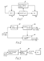
- a signal is received at a tuner 4 from an antenna 2 and is provided as the input to a descrambler 6.
- the tuner is tuned to one of the available television channels by a microprocessor logic control circuit 8.
- An output of the descrambler 6 is an input to the microprocessor 8 and provides a logic signal to the microprocessor in accordance with whether or not the descrambler has received a predetermined data code and granted access to the received signal.
- the key which enables the descrambler to do this is held in firmware in the descrambler in such a way as to be secure against discovery. Thus only subscribers whose descramblers have been fitted with the right firmware have access to the scrambled transmission. If the predetermined data code is not detected by the descrambler then the logic signal will cause the microprocessor 8 to send signals to the tuner 4 to select the next available TV channel. The same test is then carried out on this TV channel.
- the logic signal will cause the microprocessor 8 to send signals to a VCR 10 to control the recording of a descrambled television programme.
- the transmission may go into scrambled mode a few minutes before the start of the programme.
- the scrambled signal includes a data code to give the appropriate group of viewers access to the programme.
- the microprocessor 8 repeatedly controls the tuner 4 to receive each channel in turn until the logic signal from the descrambler is generated in response to the data code, indicating that access has been granted to the transmission on that channel. When access is granted to a channel, no further tuning takes place. If necessary to rewind command is sent to the VCR 10 and a few minutes later a record command is generated either before, or to coincide with the start of, the programme.
- the transmission reverts to either the clear mode or to a different scrambling sequence and data code.
- the descrambler 6 therefore no longer grants access to the transmission and after a short delay a stop command for the VCR is generated by the microprocessor 8 in response to the access logic signal from the descrambler. This short delay ensures that if there is a short break in transmission or a momentary loss of synchronisation of the descrambler recording will continue.
- the microprocessor 8 resumes controlling the tuner 4 to receive each channel in turn to find a signal to which access is granted.
- the descrambler shown in figure 2 receives an input scrambled television signal from the tuner 4 of figure 1. This signal goes to a data extractor 12 which extracts a data code transmitted with the scrambled television signal.
- the output of the data extractor 12 is coupled to an input of an authorisation checker 14 which determines whether or not the descrambler is authorised to descramble the received signal. If the descrambler is authorised then it sends a logic signal to a descrambling circuit 16 instructing the circuit to descramble the signal and to make it available at an output.
- a second output of the authorisation checker 14 is an 'access granted' logic signal which is used as the input to the microprocessor/logic circuit of figure 1.
- the embodiment of the VCR control system shown in figure 3 includes the microprocessor/logic control circuit 8 which receives the access granted logic signal from authorisation checker 14.
- the microprocessor 8 has an output connected to an infra-red remote control unit 18 which sends infra-red light signals to control the operation of the VCR 10.
- the microprocessor sends signals to simulate a sequence of key presses on the remote control unit 18 so as to cause the correct sequence of infra-red control signals to be sent to the VCR 10.
- the infra-red control unit 18 is intelligent and can be programmed to provide the infra-red light signals required by any desired VCR.
- a cable may alternatively be used to connect the remote control unit 18 to a modified VCR 10.
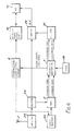
- the downloading receiver circuit shown in figure 4 comprises an antenna receiving television signals and connected to an amplifier 20.
- the amplifier output is connected to a splitter circuit 22 with outputs connected to a tuner 4 and a combiner 24.
- the television signals delivered by the antenna 2 pass through the splitter 22 to the combiner 24 which has an RF output connected to the input 24 of a VCR 10.
- Scrambled and unscrambled television signals pass through the splitter 22 to a tuner 4 which demodulates the recieved signal and which is under the control of a channel selection circuit 26. This may enable channels to be selected manually or may be underthe control of signals received from the microprocessor/logic control circuit 8, as shown by the broken line connection.
- the tuner 4 has video and audio outputs connected to the video and audio inputs of a descrambling circuit 6.
- the descrambling circuit 6 is a commercially available "Discret-12" descrambler. This provides 14 tiers of descrambling and authorisation is enabled by entering a ten-digit number in a keypad 28 coupled to the descrambler 6.
- the number entered from the keypad includes coded information as to which tiers are authorised.
- the number is combined with a unique descrambler identity code stored in firmware and with some of the transmitted data to reconstruct the scrambling sequence so that the signal can be descrambled.
- the number must have the correct relationship with a (Secret) 'Master' number stored in the scrambler.
- the significant point is that descrambling only takes place if there is a correct relationship between the keyed-in number and master number on the one hand and on the other hand the data code which is received from the tuner 4, being included in the scrambled video signal.
- the descrambler 6 has an access granted logic signal output connected to an input to the microprocessor/logic circuit 8. This has an output connected to the infra-red remote control unit 18. Operation of this portion of the circuit has been described above with reference to figures 2 and 3.
- a further two outputs of the descrambler 6 take descrambled video and descrambled audio signals to a modulator 30 which remodulates the signals.
- the modulator has an output connected to a further input of the combiner 24 which makes the modulated signal available to the VCR 10. Descrambled signals are modulated to a free RF channel to which one of the selectable channels on the VCR 10 is tuned.
- both scrambled and clear television signals pass through the circuit of figure 4 via different routes and are available at the RF input of the VCR 10.
- Descrambled signals are modulated to a free RF. channel to which one of the selective channels on the VCR 10 is tuned.
- the microprocessor 8 used may be programmable by the manufacturer or the user to perform other functions.
- channel selection and remote control are effected without data being specifically transmitted for those purposes. Also, the success of the downloading depends on the successful reception of only the scrambled channel rather than the combination of the scrambled channel and the remote control data channel.
Landscapes
- Engineering & Computer Science (AREA)
- Multimedia (AREA)
- Signal Processing (AREA)
- Computer Security & Cryptography (AREA)
- Two-Way Televisions, Distribution Of Moving Picture Or The Like (AREA)
- Television Signal Processing For Recording (AREA)
Abstract
Description
- This invention relates to the downloading of a broadcast scrambled television signal for recording in unscrambled form on a video cassette recorder (VCR), and in particular to a system for remotely controlling the downloading operation.
- Television programmes are transmitted in scrambled form so that they are available only to authorised viewers e.g. viewers who have paid for particular programme. The transmission preferably takes place at night and the programme is recorded when the transmitters are not being used for normal broadcasts.
- In its simplest form, downloading requires the viewer to programme his VCR to switch on and record a programme at the appropriate time. For this reason it is necessary for the broadcaster to announce, in advance, the time at which the broadcast will take place.
- To release the viewer from the need to programme his VCR, and the broadcaster from the need to announce the time and channel of transmission of a particular programme, control data can be transmitted with the television signal. The viewer has a data decoder responsive to the transmited control data and a remote control unit for the VCR, activated by the data decoder. Conveniently this equipment may be included in a descrambler box.
- Using such an arrangement, the broadcaster can send data signals to control the operation of the VCR functions e.g. record, rewind, stop, etc. and may thus cause a predetermined programme to be recorded. The data signal may also cause the VCR to receive signals from any channel and can also be addressed so as to only activate the VCR's of particular groups of viewers. This is necessary if a tiering facility in the scrambling system is used to make programmes available only to particular groups of viewers who have been authorised to receive them. The scrambling system in any tiering facility will operate by virtue of codes particular to such a system.
- In operation the control data will comprise specific commands to select a channel, record, stop, rewind etc. sent at appropriate times in relation to the beginning and end of the programme. The broadcaster must ensure that the addressing of the control data matches the tiering of the scrambling system.
- In accordance with one aspect of the present invention there is provided a method for downloading a scrambled television signal comprising the steps of, receiving the scrambled television signal, determining whether the received signal includes a predetermined data code, descrambling the signal when the code is detected and generating control signals for a video cassette recorder (VCR) to record the descrambled signal when the predetermined code is detected. Thus the two required functions both operate in response to the same code making the system simpler.
- The method may include the step of selectively tuning into each available television channel in turn, determining whether the selected channel contains the predetermined data code and remaining tuned to that channel when the predetermined data code is detected.
- Preferably the reception of the predetermined data code takes place before the reception of a programme to be recorded on the VCR.
- The method may also include the step of generating a delay before generating a stop signal for the VCR, the delay and stop signal being generated in response to a signal not including the predetermined data code.
- Preferably no stop signal is generated if the received signal includes the predetermined data code before the end of the delay.
- According to another aspect of the present invention there is provided a receiver for downloading a television signal comprising, means for receiving a scrambled television signal, means for determining whether the received signal includes a predetermined data code, means for descrambling the received signal, and means for effecting the recording of the descrambled signal when the pretermined data code is detected in the signal.
- The receiver may also include means for selectively tuning to each available channel to determine whether or not the selected channel incudes the predetermined data code. Preferably this selective tuning takes place repeatedly when the data code is not present in the received signal.
- The receiver may also include means for generating a delay before generating control signals for the VCR, the delay being generated when reception of the predetermined data code ceases.
- According to another aspect of the invention there is provided a transmitter for transmitting a scrambled television signal comprising input means to receive a television signal, means for scrambling the television signal, means for repeatedly inserting a predetermined data code into the scrambled signal, and means for transmitting the signal.
- The means for inserting the data code may be included in the scrambling means.
- The invention is now described in more detail by way of example with referecne to the Figures in which:
- Figure 1 shows a receiver embodying the invention;
- Figure 2 shows the structure of a descrambler for use in the invention;
- Figure 3 shows an embodiment of a control system for a VCR for use in the invention; and,
- Figure 4 is a block diagram of another receiver embodying the invention.
- In this particular embodiment of the invention, the scrambling system at the transmitter includes a data channel, one purpose of which is to control access to a programme. Thus only authorised viewers will be able to descramble and download particular programmes. The remote control operations are initiated by the onset of scrambling and the granting of access to the transmitted programme by the descrambler. The remote control commands for the VCR are generated in the appropriate sequence by a microprocessor or a logic circuit.
- In the embodiment shown in Figure 1 a signal is received at a
tuner 4 from an antenna 2 and is provided as the input to adescrambler 6. The tuner is tuned to one of the available television channels by a microprocessorlogic control circuit 8. An output of thedescrambler 6 is an input to themicroprocessor 8 and provides a logic signal to the microprocessor in accordance with whether or not the descrambler has received a predetermined data code and granted access to the received signal. The key which enables the descrambler to do this is held in firmware in the descrambler in such a way as to be secure against discovery. Thus only subscribers whose descramblers have been fitted with the right firmware have access to the scrambled transmission. If the predetermined data code is not detected by the descrambler then the logic signal will cause themicroprocessor 8 to send signals to thetuner 4 to select the next available TV channel. The same test is then carried out on this TV channel. - If the predetermined data code is detected by the descrambler then the logic signal will cause the
microprocessor 8 to send signals to aVCR 10 to control the recording of a descrambled television programme. - In operation, the transmission may go into scrambled mode a few minutes before the start of the programme. The scrambled signal includes a data code to give the appropriate group of viewers access to the programme. The
microprocessor 8 repeatedly controls thetuner 4 to receive each channel in turn until the logic signal from the descrambler is generated in response to the data code, indicating that access has been granted to the transmission on that channel. When access is granted to a channel, no further tuning takes place. If necessary to rewind command is sent to theVCR 10 and a few minutes later a record command is generated either before, or to coincide with the start of, the programme. - After the end of the programme, the transmission reverts to either the clear mode or to a different scrambling sequence and data code. The
descrambler 6 therefore no longer grants access to the transmission and after a short delay a stop command for the VCR is generated by themicroprocessor 8 in response to the access logic signal from the descrambler. This short delay ensures that if there is a short break in transmission or a momentary loss of synchronisation of the descrambler recording will continue. After the end of the programme, themicroprocessor 8 resumes controlling thetuner 4 to receive each channel in turn to find a signal to which access is granted. - The descrambler shown in figure 2 receives an input scrambled television signal from the
tuner 4 of figure 1. This signal goes to adata extractor 12 which extracts a data code transmitted with the scrambled television signal. The output of thedata extractor 12 is coupled to an input of anauthorisation checker 14 which determines whether or not the descrambler is authorised to descramble the received signal. If the descrambler is authorised then it sends a logic signal to a descramblingcircuit 16 instructing the circuit to descramble the signal and to make it available at an output. A second output of theauthorisation checker 14 is an 'access granted' logic signal which is used as the input to the microprocessor/logic circuit of figure 1. - The embodiment of the VCR control system shown in figure 3 includes the microprocessor/
logic control circuit 8 which receives the access granted logic signal fromauthorisation checker 14. Themicroprocessor 8 has an output connected to an infra-redremote control unit 18 which sends infra-red light signals to control the operation of theVCR 10. The microprocessor sends signals to simulate a sequence of key presses on theremote control unit 18 so as to cause the correct sequence of infra-red control signals to be sent to theVCR 10. - In a preferred embodiment the infra-
red control unit 18 is intelligent and can be programmed to provide the infra-red light signals required by any desired VCR. - A cable may alternatively be used to connect the
remote control unit 18 to a modifiedVCR 10. - The downloading receiver circuit shown in figure 4 comprises an antenna receiving television signals and connected to an amplifier 20. The amplifier output is connected to a
splitter circuit 22 with outputs connected to atuner 4 and acombiner 24. The television signals delivered by the antenna 2 pass through thesplitter 22 to thecombiner 24 which has an RF output connected to theinput 24 of aVCR 10. - Scrambled and unscrambled television signals pass through the
splitter 22 to atuner 4 which demodulates the recieved signal and which is under the control of achannel selection circuit 26. This may enable channels to be selected manually or may be underthe control of signals received from the microprocessor/logic control circuit 8, as shown by the broken line connection. - The
tuner 4 has video and audio outputs connected to the video and audio inputs of adescrambling circuit 6. In this example thedescrambling circuit 6 is a commercially available "Discret-12" descrambler. This provides 14 tiers of descrambling and authorisation is enabled by entering a ten-digit number in akeypad 28 coupled to thedescrambler 6. The number entered from the keypad includes coded information as to which tiers are authorised. The number is combined with a unique descrambler identity code stored in firmware and with some of the transmitted data to reconstruct the scrambling sequence so that the signal can be descrambled. In addition the number must have the correct relationship with a (Secret) 'Master' number stored in the scrambler. So far as the present invention is concerned, the significant point is that descrambling only takes place if there is a correct relationship between the keyed-in number and master number on the one hand and on the other hand the data code which is received from thetuner 4, being included in the scrambled video signal. - The
descrambler 6 has an access granted logic signal output connected to an input to the microprocessor/logic circuit 8. This has an output connected to the infra-redremote control unit 18. Operation of this portion of the circuit has been described above with reference to figures 2 and 3. - A further two outputs of the
descrambler 6 take descrambled video and descrambled audio signals to amodulator 30 which remodulates the signals. - The modulator has an output connected to a further input of the
combiner 24 which makes the modulated signal available to theVCR 10. Descrambled signals are modulated to a free RF channel to which one of the selectable channels on theVCR 10 is tuned. - Thus it will be appreciated that both scrambled and clear television signals pass through the circuit of figure 4 via different routes and are available at the RF input of the
VCR 10. Descrambled signals are modulated to a free RF. channel to which one of the selective channels on theVCR 10 is tuned. - The
microprocessor 8 used may be programmable by the manufacturer or the user to perform other functions. - With the invention described above, channel selection and remote control are effected without data being specifically transmitted for those purposes. Also, the success of the downloading depends on the successful reception of only the scrambled channel rather than the combination of the scrambled channel and the remote control data channel.
Claims (13)
Applications Claiming Priority (2)
| Application Number | Priority Date | Filing Date | Title |
|---|---|---|---|
| GB888809514A GB8809514D0 (en) | 1988-04-22 | 1988-04-22 | Remote control system for downloading |
| GB8809514 | 1988-04-22 |
Publications (2)
| Publication Number | Publication Date |
|---|---|
| EP0338866A2 true EP0338866A2 (en) | 1989-10-25 |
| EP0338866A3 EP0338866A3 (en) | 1992-04-29 |
Family
ID=10635637
Family Applications (1)
| Application Number | Title | Priority Date | Filing Date |
|---|---|---|---|
| EP19890304038 Withdrawn EP0338866A3 (en) | 1988-04-22 | 1989-04-24 | Method for downloading a scrambled television signal and receiver therefor |
Country Status (2)
| Country | Link |
|---|---|
| EP (1) | EP0338866A3 (en) |
| GB (2) | GB8809514D0 (en) |
Cited By (7)
| Publication number | Priority date | Publication date | Assignee | Title |
|---|---|---|---|---|
| EP0543668A1 (en) * | 1991-11-22 | 1993-05-26 | Sony Corporation | Apparatus for receiving scrambled signals and recording method |
| EP0589459A1 (en) * | 1992-09-24 | 1994-03-30 | Matsushita Electric Industrial Co., Ltd. | Recording and reproducing apparatus |
| EP0592233A1 (en) * | 1992-10-09 | 1994-04-13 | Sony Corporation | Scramble system for prevention illegal user |
| EP0675655A2 (en) * | 1994-03-28 | 1995-10-04 | Hitachi, Ltd. | Method and system for transsion/reception of encrypted digital signal |
| US6163644A (en) * | 1995-04-27 | 2000-12-19 | Hitachi, Ltd. | Method and apparatus for receiving and/or reproducing digital signal |
| US6600870B1 (en) | 1994-10-28 | 2003-07-29 | Hitachi, Ltd. | Input-output circuit, recording apparatus and reproduction apparatus for digital video signal |
| WO2006062225A1 (en) * | 2004-12-08 | 2006-06-15 | Matsushita Electric Industrial Co. Ltd. | Digital broadcast recording apparatus |
Citations (7)
| Publication number | Priority date | Publication date | Assignee | Title |
|---|---|---|---|---|
| US3729581A (en) * | 1970-09-03 | 1973-04-24 | Display Sys Corp | Computer assisted dial access video retrieval for an instructional television system |
| AU536261B2 (en) * | 1979-04-16 | 1984-05-03 | Codart Inc. | Broadcast monitor |
| EP0120615A1 (en) * | 1983-02-28 | 1984-10-03 | Sony Corporation | Apparatus for, and method of, recording scrambled or coded television signals |
| JPS6054583A (en) * | 1983-09-05 | 1985-03-29 | Sony Corp | Descrambling device |
| EP0179001A2 (en) * | 1984-10-19 | 1986-04-23 | Francis Fabien Michel Muguet | Method and apparatus for acquisition, memorizing and transmission of specialized data, in particular concerning the recording of broadcasts, between an apparatus such as a video recorder and a processing centre |
| US4630133A (en) * | 1982-12-20 | 1986-12-16 | Zenith Electronics Corporation | VCR with total record/view flexibility |
| DE3628964A1 (en) * | 1986-08-26 | 1988-03-10 | Standard Elektrik Lorenz Ag | METHOD FOR TRIGGERING A SWITCHING FUNCTION IN A PROGRAMMABLE RECEIVER OF THE ENTERTAINMENT ELECTRONICS |
Family Cites Families (2)
| Publication number | Priority date | Publication date | Assignee | Title |
|---|---|---|---|---|
| JPS59165585A (en) * | 1983-03-09 | 1984-09-18 | Sony Corp | Television signal receiver |
| EP0267039A3 (en) * | 1986-11-05 | 1990-04-04 | Satellite Technology Services, Inc. | Video system and method for controlled videotaping |
-
1988
- 1988-04-22 GB GB888809514A patent/GB8809514D0/en active Pending
-
1989
- 1989-04-24 EP EP19890304038 patent/EP0338866A3/en not_active Withdrawn
- 1989-04-24 GB GB8909323A patent/GB2219160B/en not_active Expired - Fee Related
Patent Citations (7)
| Publication number | Priority date | Publication date | Assignee | Title |
|---|---|---|---|---|
| US3729581A (en) * | 1970-09-03 | 1973-04-24 | Display Sys Corp | Computer assisted dial access video retrieval for an instructional television system |
| AU536261B2 (en) * | 1979-04-16 | 1984-05-03 | Codart Inc. | Broadcast monitor |
| US4630133A (en) * | 1982-12-20 | 1986-12-16 | Zenith Electronics Corporation | VCR with total record/view flexibility |
| EP0120615A1 (en) * | 1983-02-28 | 1984-10-03 | Sony Corporation | Apparatus for, and method of, recording scrambled or coded television signals |
| JPS6054583A (en) * | 1983-09-05 | 1985-03-29 | Sony Corp | Descrambling device |
| EP0179001A2 (en) * | 1984-10-19 | 1986-04-23 | Francis Fabien Michel Muguet | Method and apparatus for acquisition, memorizing and transmission of specialized data, in particular concerning the recording of broadcasts, between an apparatus such as a video recorder and a processing centre |
| DE3628964A1 (en) * | 1986-08-26 | 1988-03-10 | Standard Elektrik Lorenz Ag | METHOD FOR TRIGGERING A SWITCHING FUNCTION IN A PROGRAMMABLE RECEIVER OF THE ENTERTAINMENT ELECTRONICS |
Non-Patent Citations (1)
| Title |
|---|
| PATENT ABSTRACTS OF JAPAN, vol. 9, no. 185 (E-332), 31st July 1985; & JP-A-60 054 583 (SONY K.K.) 29-03-1985 * |
Cited By (24)
| Publication number | Priority date | Publication date | Assignee | Title |
|---|---|---|---|---|
| KR100236741B1 (en) * | 1991-11-22 | 2000-01-15 | 이데이 노부유끼 | Receiving apparatus and recording method |
| US5406625A (en) * | 1991-11-22 | 1995-04-11 | Sony Corporation | Receiving apparatus and recording method |
| EP0543668A1 (en) * | 1991-11-22 | 1993-05-26 | Sony Corporation | Apparatus for receiving scrambled signals and recording method |
| EP0589459A1 (en) * | 1992-09-24 | 1994-03-30 | Matsushita Electric Industrial Co., Ltd. | Recording and reproducing apparatus |
| EP0592233A1 (en) * | 1992-10-09 | 1994-04-13 | Sony Corporation | Scramble system for prevention illegal user |
| US5579391A (en) * | 1992-10-09 | 1996-11-26 | Sony Corporation | TV scramble system for preventing illegal reception |
| EP0675655A3 (en) * | 1994-03-28 | 1997-09-24 | Hitachi Ltd | Method and system for transmission/reception of encrypted digital signal. |
| US5719943A (en) * | 1994-03-28 | 1998-02-17 | Hitachi, Ltd. | Digital information signal transmitting/receiving method and system |
| EP0675655A2 (en) * | 1994-03-28 | 1995-10-04 | Hitachi, Ltd. | Method and system for transsion/reception of encrypted digital signal |
| US8254758B2 (en) | 1994-10-28 | 2012-08-28 | Hitachi Consumer Electronics Co., Ltd. | Input-output circuit, recording apparatus and reproduction apparatus for digital video signal |
| US8340501B2 (en) | 1994-10-28 | 2012-12-25 | Hitachi Consumer Electronics Co., Ltd. | Input-output circuit, recording apparatus and reproduction apparatus for digital video signal |
| US8306395B2 (en) | 1994-10-28 | 2012-11-06 | Hitachi Consumer Electronics Co., Ltd. | Input-output circuit, recording apparatus and reproduction apparatus for digital video signal |
| US6600870B1 (en) | 1994-10-28 | 2003-07-29 | Hitachi, Ltd. | Input-output circuit, recording apparatus and reproduction apparatus for digital video signal |
| US8270812B2 (en) | 1994-10-28 | 2012-09-18 | Hitachi Consumer Electronics Co., Ltd. | Input-output circuit, recording apparatus and reproduction apparatus for digital video signal |
| US7319808B2 (en) | 1994-10-28 | 2008-01-15 | Hitachi, Ltd. | Input-output circuit, recording apparatus and reproduction apparatus for digital video signal |
| US6757478B2 (en) | 1995-04-27 | 2004-06-29 | Hitachi, Ltd. | Method and apparatus for receiving a digital signal and apparatus for recording and reproducing the digital signal |
| US7844986B2 (en) | 1995-04-27 | 2010-11-30 | Hitachi Consumer Electronics Co., Ltd. | Method and apparatus for receiving a digital signal and apparatus for recording and reproducing the digital signal |
| US6321025B1 (en) | 1995-04-27 | 2001-11-20 | Hitachi, Ltd | Method and apparatus for receiving and/or reproducing digital signal |
| US6163644A (en) * | 1995-04-27 | 2000-12-19 | Hitachi, Ltd. | Method and apparatus for receiving and/or reproducing digital signal |
| US8699864B2 (en) | 1995-04-27 | 2014-04-15 | Hitachi Consumer Electronics Co., Ltd. | Method and apparatus for receiving a digital signal and apparatus for recording and reproducing the digital signal |
| USRE42622E1 (en) | 2004-12-08 | 2011-08-16 | Panasonic Corporation | Digital broadcast recording apparatus |
| CN101640776B (en) * | 2004-12-08 | 2012-02-22 | 松下电器产业株式会社 | Digital broadcast recording apparatus and method |
| US7558470B2 (en) | 2004-12-08 | 2009-07-07 | Panasonic Corporation | Digital broadcast recording apparatus |
| WO2006062225A1 (en) * | 2004-12-08 | 2006-06-15 | Matsushita Electric Industrial Co. Ltd. | Digital broadcast recording apparatus |
Also Published As
| Publication number | Publication date |
|---|---|
| GB8909323D0 (en) | 1989-06-07 |
| GB2219160A (en) | 1989-11-29 |
| GB2219160B (en) | 1992-05-27 |
| GB8809514D0 (en) | 1988-05-25 |
| EP0338866A3 (en) | 1992-04-29 |
Similar Documents
| Publication | Publication Date | Title |
|---|---|---|
| US5297204A (en) | VCR with cable tuner control | |
| USRE35954E (en) | VCR with cable tuner control | |
| US5629868A (en) | Method of programming local control | |
| EP0492853B1 (en) | Remote channel switching for video on demand service | |
| US5323234A (en) | Programmable CATV system and terminal unit therefor | |
| US4995080A (en) | Television signal scrambling system and method | |
| US5341166A (en) | System for controlling selected devices having unique sets of control codes | |
| US5467197A (en) | Dual communication mode video tape recorder | |
| US5285272A (en) | Video store and forward on demand apparatus and method | |
| EP0672323B1 (en) | Auxiliary device control for a subscriber terminal | |
| US5497185A (en) | Remote control system for television audience data gathering | |
| EP0060299B1 (en) | Multiple signal transmission method and system, particularly for television | |
| USRE42026E1 (en) | Television system module with remote control code determination | |
| GB2215928A (en) | Controlling a video recorder by a coded broadcast signal | |
| WO1996036172A3 (en) | Vps compatible apparatus and method using compressed codes for ir code selection | |
| EP0178866A1 (en) | Image reception apparatus | |
| EP0627857B1 (en) | Method for programming a recording device and programming device | |
| EP0945014B1 (en) | A television apparatus control system | |
| EP0338866A2 (en) | Method for downloading a scrambled television signal and receiver therefor | |
| JPS59210782A (en) | Television set | |
| EP0508394B1 (en) | Method for controlling a recording device | |
| AU7493891A (en) | Apparatus and method for controlling a recording machine | |
| US5343528A (en) | Procedure and decoder for decrypting a coded video signal | |
| JPH03280684A (en) | Equipment for catv | |
| TW376657B (en) | Dynamic relocation of the service data channel |
Legal Events
| Date | Code | Title | Description |
|---|---|---|---|
| PUAI | Public reference made under article 153(3) epc to a published international application that has entered the european phase |
Free format text: ORIGINAL CODE: 0009012 |
|
| AK | Designated contracting states |
Kind code of ref document: A2 Designated state(s): AT BE CH DE ES FR GR IT LI LU NL SE |
|
| 17P | Request for examination filed |
Effective date: 19900328 |
|
| PUAL | Search report despatched |
Free format text: ORIGINAL CODE: 0009013 |
|
| AK | Designated contracting states |
Kind code of ref document: A3 Designated state(s): AT BE CH DE ES FR GR IT LI LU NL SE |
|
| STAA | Information on the status of an ep patent application or granted ep patent |
Free format text: STATUS: THE APPLICATION HAS BEEN WITHDRAWN |
|
| 17Q | First examination report despatched |
Effective date: 19940505 |
|
| 18W | Application withdrawn |
Withdrawal date: 19940506 |