EP0338751A2 - Stereolithographic supports - Google Patents
Stereolithographic supports Download PDFInfo
- Publication number
- EP0338751A2 EP0338751A2 EP89303786A EP89303786A EP0338751A2 EP 0338751 A2 EP0338751 A2 EP 0338751A2 EP 89303786 A EP89303786 A EP 89303786A EP 89303786 A EP89303786 A EP 89303786A EP 0338751 A2 EP0338751 A2 EP 0338751A2
- Authority
- EP
- European Patent Office
- Prior art keywords
- supports
- set forth
- specifies
- improved
- data
- Prior art date
- Legal status (The legal status is an assumption and is not a legal conclusion. Google has not performed a legal analysis and makes no representation as to the accuracy of the status listed.)
- Granted
Links
- 238000000034 method Methods 0.000 claims description 61
- 239000013598 vector Substances 0.000 claims description 35
- 239000012530 fluid Substances 0.000 abstract description 28
- 230000000638 stimulation Effects 0.000 abstract description 10
- 230000002195 synergetic effect Effects 0.000 abstract description 7
- 230000005855 radiation Effects 0.000 abstract description 6
- 230000004044 response Effects 0.000 abstract description 6
- 238000006243 chemical reaction Methods 0.000 abstract description 5
- 239000002245 particle Substances 0.000 abstract description 3
- 239000007788 liquid Substances 0.000 description 60
- 238000011960 computer-aided design Methods 0.000 description 38
- 238000013461 design Methods 0.000 description 38
- 238000004519 manufacturing process Methods 0.000 description 33
- 239000004033 plastic Substances 0.000 description 30
- 229920003023 plastic Polymers 0.000 description 30
- 239000000463 material Substances 0.000 description 25
- 239000007787 solid Substances 0.000 description 22
- 230000008569 process Effects 0.000 description 18
- 239000011347 resin Substances 0.000 description 8
- 229920005989 resin Polymers 0.000 description 8
- 239000011343 solid material Substances 0.000 description 8
- 238000001723 curing Methods 0.000 description 6
- 230000008859 change Effects 0.000 description 5
- 238000007598 dipping method Methods 0.000 description 5
- 229910052751 metal Inorganic materials 0.000 description 5
- 239000002184 metal Substances 0.000 description 5
- 239000000126 substance Substances 0.000 description 5
- 230000001070 adhesive effect Effects 0.000 description 4
- 230000008901 benefit Effects 0.000 description 4
- 230000012447 hatching Effects 0.000 description 4
- 238000012805 post-processing Methods 0.000 description 4
- 238000007639 printing Methods 0.000 description 4
- 238000012545 processing Methods 0.000 description 4
- LYCAIKOWRPUZTN-UHFFFAOYSA-N Ethylene glycol Chemical compound OCCO LYCAIKOWRPUZTN-UHFFFAOYSA-N 0.000 description 3
- 238000010521 absorption reaction Methods 0.000 description 3
- 238000010586 diagram Methods 0.000 description 3
- 238000010894 electron beam technology Methods 0.000 description 3
- 238000005516 engineering process Methods 0.000 description 3
- 238000001746 injection moulding Methods 0.000 description 3
- XLYOFNOQVPJJNP-ZSJDYOACSA-N Heavy water Chemical compound [2H]O[2H] XLYOFNOQVPJJNP-ZSJDYOACSA-N 0.000 description 2
- 238000012356 Product development Methods 0.000 description 2
- 239000000853 adhesive Substances 0.000 description 2
- 238000013459 approach Methods 0.000 description 2
- 230000015572 biosynthetic process Effects 0.000 description 2
- UIZLQMLDSWKZGC-UHFFFAOYSA-N cadmium helium Chemical compound [He].[Cd] UIZLQMLDSWKZGC-UHFFFAOYSA-N 0.000 description 2
- 238000004891 communication Methods 0.000 description 2
- 238000011161 development Methods 0.000 description 2
- 230000018109 developmental process Effects 0.000 description 2
- 238000006073 displacement reaction Methods 0.000 description 2
- 238000007667 floating Methods 0.000 description 2
- 230000006870 function Effects 0.000 description 2
- 230000006872 improvement Effects 0.000 description 2
- IXHBTMCLRNMKHZ-LBPRGKRZSA-N levobunolol Chemical compound O=C1CCCC2=C1C=CC=C2OC[C@@H](O)CNC(C)(C)C IXHBTMCLRNMKHZ-LBPRGKRZSA-N 0.000 description 2
- 238000001459 lithography Methods 0.000 description 2
- 238000003801 milling Methods 0.000 description 2
- 230000003287 optical effect Effects 0.000 description 2
- 229920000642 polymer Polymers 0.000 description 2
- 238000007711 solidification Methods 0.000 description 2
- 230000008023 solidification Effects 0.000 description 2
- 238000005507 spraying Methods 0.000 description 2
- 238000012549 training Methods 0.000 description 2
- 230000007704 transition Effects 0.000 description 2
- 238000010146 3D printing Methods 0.000 description 1
- CBENFWSGALASAD-UHFFFAOYSA-N Ozone Chemical compound [O-][O+]=O CBENFWSGALASAD-UHFFFAOYSA-N 0.000 description 1
- 230000009471 action Effects 0.000 description 1
- 229910052782 aluminium Inorganic materials 0.000 description 1
- XAGFODPZIPBFFR-UHFFFAOYSA-N aluminium Chemical compound [Al] XAGFODPZIPBFFR-UHFFFAOYSA-N 0.000 description 1
- 238000005452 bending Methods 0.000 description 1
- 239000000227 bioadhesive Substances 0.000 description 1
- 239000004566 building material Substances 0.000 description 1
- 238000004364 calculation method Methods 0.000 description 1
- 239000011248 coating agent Substances 0.000 description 1
- 238000000576 coating method Methods 0.000 description 1
- 239000003086 colorant Substances 0.000 description 1
- 239000004020 conductor Substances 0.000 description 1
- 238000013523 data management Methods 0.000 description 1
- 230000007423 decrease Effects 0.000 description 1
- 238000001514 detection method Methods 0.000 description 1
- 238000009792 diffusion process Methods 0.000 description 1
- 239000006185 dispersion Substances 0.000 description 1
- 230000000694 effects Effects 0.000 description 1
- 230000007717 exclusion Effects 0.000 description 1
- 238000011049 filling Methods 0.000 description 1
- 239000010408 film Substances 0.000 description 1
- 239000003517 fume Substances 0.000 description 1
- 239000011521 glass Substances 0.000 description 1
- 238000013007 heat curing Methods 0.000 description 1
- 238000002347 injection Methods 0.000 description 1
- 239000007924 injection Substances 0.000 description 1
- 238000009434 installation Methods 0.000 description 1
- 239000011810 insulating material Substances 0.000 description 1
- 230000002452 interceptive effect Effects 0.000 description 1
- 238000011031 large-scale manufacturing process Methods 0.000 description 1
- 239000011344 liquid material Substances 0.000 description 1
- 238000004377 microelectronic Methods 0.000 description 1
- 238000001393 microlithography Methods 0.000 description 1
- 238000012986 modification Methods 0.000 description 1
- 230000004048 modification Effects 0.000 description 1
- 231100000344 non-irritating Toxicity 0.000 description 1
- 231100000252 nontoxic Toxicity 0.000 description 1
- 230000003000 nontoxic effect Effects 0.000 description 1
- 230000001473 noxious effect Effects 0.000 description 1
- 238000005457 optimization Methods 0.000 description 1
- 230000000149 penetrating effect Effects 0.000 description 1
- 238000006116 polymerization reaction Methods 0.000 description 1
- 238000011417 postcuring Methods 0.000 description 1
- 238000002360 preparation method Methods 0.000 description 1
- 239000010453 quartz Substances 0.000 description 1
- 230000002040 relaxant effect Effects 0.000 description 1
- 238000007665 sagging Methods 0.000 description 1
- VYPSYNLAJGMNEJ-UHFFFAOYSA-N silicon dioxide Inorganic materials O=[Si]=O VYPSYNLAJGMNEJ-UHFFFAOYSA-N 0.000 description 1
- 239000002904 solvent Substances 0.000 description 1
- 230000003068 static effect Effects 0.000 description 1
- 238000006467 substitution reaction Methods 0.000 description 1
- 239000010409 thin film Substances 0.000 description 1
- 238000013519 translation Methods 0.000 description 1
- 238000007666 vacuum forming Methods 0.000 description 1
- 239000011800 void material Substances 0.000 description 1
- 239000002699 waste material Substances 0.000 description 1
- 238000009736 wetting Methods 0.000 description 1
Images


Classifications
-
- B—PERFORMING OPERATIONS; TRANSPORTING
- B29—WORKING OF PLASTICS; WORKING OF SUBSTANCES IN A PLASTIC STATE IN GENERAL
- B29C—SHAPING OR JOINING OF PLASTICS; SHAPING OF MATERIAL IN A PLASTIC STATE, NOT OTHERWISE PROVIDED FOR; AFTER-TREATMENT OF THE SHAPED PRODUCTS, e.g. REPAIRING
- B29C35/00—Heating, cooling or curing, e.g. crosslinking or vulcanising; Apparatus therefor
- B29C35/02—Heating or curing, e.g. crosslinking or vulcanizing during moulding, e.g. in a mould
- B29C35/08—Heating or curing, e.g. crosslinking or vulcanizing during moulding, e.g. in a mould by wave energy or particle radiation
-
- G—PHYSICS
- G06—COMPUTING; CALCULATING OR COUNTING
- G06T—IMAGE DATA PROCESSING OR GENERATION, IN GENERAL
- G06T17/00—Three dimensional [3D] modelling, e.g. data description of 3D objects
- G06T17/20—Finite element generation, e.g. wire-frame surface description, tesselation
-
- B—PERFORMING OPERATIONS; TRANSPORTING
- B29—WORKING OF PLASTICS; WORKING OF SUBSTANCES IN A PLASTIC STATE IN GENERAL
- B29C—SHAPING OR JOINING OF PLASTICS; SHAPING OF MATERIAL IN A PLASTIC STATE, NOT OTHERWISE PROVIDED FOR; AFTER-TREATMENT OF THE SHAPED PRODUCTS, e.g. REPAIRING
- B29C41/00—Shaping by coating a mould, core or other substrate, i.e. by depositing material and stripping-off the shaped article; Apparatus therefor
- B29C41/02—Shaping by coating a mould, core or other substrate, i.e. by depositing material and stripping-off the shaped article; Apparatus therefor for making articles of definite length, i.e. discrete articles
- B29C41/12—Spreading-out the material on a substrate, e.g. on the surface of a liquid
-
- B—PERFORMING OPERATIONS; TRANSPORTING
- B29—WORKING OF PLASTICS; WORKING OF SUBSTANCES IN A PLASTIC STATE IN GENERAL
- B29C—SHAPING OR JOINING OF PLASTICS; SHAPING OF MATERIAL IN A PLASTIC STATE, NOT OTHERWISE PROVIDED FOR; AFTER-TREATMENT OF THE SHAPED PRODUCTS, e.g. REPAIRING
- B29C41/00—Shaping by coating a mould, core or other substrate, i.e. by depositing material and stripping-off the shaped article; Apparatus therefor
- B29C41/34—Component parts, details or accessories; Auxiliary operations
- B29C41/36—Feeding the material on to the mould, core or other substrate
-
- B—PERFORMING OPERATIONS; TRANSPORTING
- B29—WORKING OF PLASTICS; WORKING OF SUBSTANCES IN A PLASTIC STATE IN GENERAL
- B29C—SHAPING OR JOINING OF PLASTICS; SHAPING OF MATERIAL IN A PLASTIC STATE, NOT OTHERWISE PROVIDED FOR; AFTER-TREATMENT OF THE SHAPED PRODUCTS, e.g. REPAIRING
- B29C64/00—Additive manufacturing, i.e. manufacturing of three-dimensional [3D] objects by additive deposition, additive agglomeration or additive layering, e.g. by 3D printing, stereolithography or selective laser sintering
- B29C64/10—Processes of additive manufacturing
- B29C64/106—Processes of additive manufacturing using only liquids or viscous materials, e.g. depositing a continuous bead of viscous material
- B29C64/124—Processes of additive manufacturing using only liquids or viscous materials, e.g. depositing a continuous bead of viscous material using layers of liquid which are selectively solidified
- B29C64/129—Processes of additive manufacturing using only liquids or viscous materials, e.g. depositing a continuous bead of viscous material using layers of liquid which are selectively solidified characterised by the energy source therefor, e.g. by global irradiation combined with a mask
- B29C64/135—Processes of additive manufacturing using only liquids or viscous materials, e.g. depositing a continuous bead of viscous material using layers of liquid which are selectively solidified characterised by the energy source therefor, e.g. by global irradiation combined with a mask the energy source being concentrated, e.g. scanning lasers or focused light sources
-
- B—PERFORMING OPERATIONS; TRANSPORTING
- B29—WORKING OF PLASTICS; WORKING OF SUBSTANCES IN A PLASTIC STATE IN GENERAL
- B29C—SHAPING OR JOINING OF PLASTICS; SHAPING OF MATERIAL IN A PLASTIC STATE, NOT OTHERWISE PROVIDED FOR; AFTER-TREATMENT OF THE SHAPED PRODUCTS, e.g. REPAIRING
- B29C64/00—Additive manufacturing, i.e. manufacturing of three-dimensional [3D] objects by additive deposition, additive agglomeration or additive layering, e.g. by 3D printing, stereolithography or selective laser sintering
- B29C64/40—Structures for supporting 3D objects during manufacture and intended to be sacrificed after completion thereof
-
- B—PERFORMING OPERATIONS; TRANSPORTING
- B29—WORKING OF PLASTICS; WORKING OF SUBSTANCES IN A PLASTIC STATE IN GENERAL
- B29C—SHAPING OR JOINING OF PLASTICS; SHAPING OF MATERIAL IN A PLASTIC STATE, NOT OTHERWISE PROVIDED FOR; AFTER-TREATMENT OF THE SHAPED PRODUCTS, e.g. REPAIRING
- B29C67/00—Shaping techniques not covered by groups B29C39/00 - B29C65/00, B29C70/00 or B29C73/00
-
- G—PHYSICS
- G01—MEASURING; TESTING
- G01J—MEASUREMENT OF INTENSITY, VELOCITY, SPECTRAL CONTENT, POLARISATION, PHASE OR PULSE CHARACTERISTICS OF INFRARED, VISIBLE OR ULTRAVIOLET LIGHT; COLORIMETRY; RADIATION PYROMETRY
- G01J1/00—Photometry, e.g. photographic exposure meter
- G01J1/42—Photometry, e.g. photographic exposure meter using electric radiation detectors
- G01J1/4257—Photometry, e.g. photographic exposure meter using electric radiation detectors applied to monitoring the characteristics of a beam, e.g. laser beam, headlamp beam
-
- G—PHYSICS
- G03—PHOTOGRAPHY; CINEMATOGRAPHY; ANALOGOUS TECHNIQUES USING WAVES OTHER THAN OPTICAL WAVES; ELECTROGRAPHY; HOLOGRAPHY
- G03F—PHOTOMECHANICAL PRODUCTION OF TEXTURED OR PATTERNED SURFACES, e.g. FOR PRINTING, FOR PROCESSING OF SEMICONDUCTOR DEVICES; MATERIALS THEREFOR; ORIGINALS THEREFOR; APPARATUS SPECIALLY ADAPTED THEREFOR
- G03F7/00—Photomechanical, e.g. photolithographic, production of textured or patterned surfaces, e.g. printing surfaces; Materials therefor, e.g. comprising photoresists; Apparatus specially adapted therefor
- G03F7/0037—Production of three-dimensional images
-
- G—PHYSICS
- G03—PHOTOGRAPHY; CINEMATOGRAPHY; ANALOGOUS TECHNIQUES USING WAVES OTHER THAN OPTICAL WAVES; ELECTROGRAPHY; HOLOGRAPHY
- G03F—PHOTOMECHANICAL PRODUCTION OF TEXTURED OR PATTERNED SURFACES, e.g. FOR PRINTING, FOR PROCESSING OF SEMICONDUCTOR DEVICES; MATERIALS THEREFOR; ORIGINALS THEREFOR; APPARATUS SPECIALLY ADAPTED THEREFOR
- G03F7/00—Photomechanical, e.g. photolithographic, production of textured or patterned surfaces, e.g. printing surfaces; Materials therefor, e.g. comprising photoresists; Apparatus specially adapted therefor
- G03F7/70—Microphotolithographic exposure; Apparatus therefor
- G03F7/70416—2.5D lithography
-
- G—PHYSICS
- G06—COMPUTING; CALCULATING OR COUNTING
- G06T—IMAGE DATA PROCESSING OR GENERATION, IN GENERAL
- G06T17/00—Three dimensional [3D] modelling, e.g. data description of 3D objects
-
- G—PHYSICS
- G06—COMPUTING; CALCULATING OR COUNTING
- G06T—IMAGE DATA PROCESSING OR GENERATION, IN GENERAL
- G06T17/00—Three dimensional [3D] modelling, e.g. data description of 3D objects
- G06T17/10—Constructive solid geometry [CSG] using solid primitives, e.g. cylinders, cubes
-
- G—PHYSICS
- G05—CONTROLLING; REGULATING
- G05B—CONTROL OR REGULATING SYSTEMS IN GENERAL; FUNCTIONAL ELEMENTS OF SUCH SYSTEMS; MONITORING OR TESTING ARRANGEMENTS FOR SUCH SYSTEMS OR ELEMENTS
- G05B2219/00—Program-control systems
- G05B2219/30—Nc systems
- G05B2219/49—Nc machine tool, till multiple
- G05B2219/49013—Deposit layers, cured by scanning laser, stereo lithography SLA, prototyping
-
- G—PHYSICS
- G05—CONTROLLING; REGULATING
- G05B—CONTROL OR REGULATING SYSTEMS IN GENERAL; FUNCTIONAL ELEMENTS OF SUCH SYSTEMS; MONITORING OR TESTING ARRANGEMENTS FOR SUCH SYSTEMS OR ELEMENTS
- G05B2219/00—Program-control systems
- G05B2219/30—Nc systems
- G05B2219/49—Nc machine tool, till multiple
- G05B2219/49015—Wire, strang laying, deposit fluid, welding, adhesive, hardening, solidification, fuse
-
- G—PHYSICS
- G05—CONTROLLING; REGULATING
- G05B—CONTROL OR REGULATING SYSTEMS IN GENERAL; FUNCTIONAL ELEMENTS OF SUCH SYSTEMS; MONITORING OR TESTING ARRANGEMENTS FOR SUCH SYSTEMS OR ELEMENTS
- G05B2219/00—Program-control systems
- G05B2219/30—Nc systems
- G05B2219/49—Nc machine tool, till multiple
- G05B2219/49039—Build layer of different, weaker material between support and prototype
Definitions
- This invention relates generally to improvements in methods and apparatus for forming three-dimensional objects from a fluid medium and, more particularly, to a new and improved stereolithography system involving the application of enhanced data manipulation and lithographic techniques to production of three-dimensional objects, whereby such objects can be formed more rapidly, reliably, . accurately and economically.
- this invention relates to stereolithographic supports for the object.
- plastic parts and the like It is common practice in the production of plastic parts and the like to first design such a part and then painstakingly produce a prototype of the part, all involving considerable time, effort and expense. The design is then reviewed and, often- times, the laborious process is again and again repeated until the design has been optimized. After design optimization, the next step is production. Most production plastic parts are injection molded. Since the design time and tooling costs are very high, plastic parts are usually only practical in high volume production. While other processes are available for the production of plastic parts, including direct machine work, vacuum-forming and direct forming, such methods are typically only cost effective for short run production, and the parts produced are usually inferior in quality to molded parts.
- stereolithography is a method for automatically building complex plastic parts by successively printing cross-sections of photopolymer (such as liquid plastic) on top of each other until all of the thin layers are joined together to form a whole part.
- photopolymer such as liquid plastic
- Photocurable polymers change from liquid to solid in the presence of light and their photospeed with ultraviolet light is fast enough to make them practical model building materials.
- the material that is not polymerized when a part is made is still usable and remains in the vat as successive parts are made.
- An ultraviolet-laser generates a small intense spot of UV. This spot is moved across the liquid surface with a galvanometer mirror X-Y scanner. The scanner is driven by computer generated vectors or the like. Precise complex patterns can be rapidly produced with this technique.
- SLA stereolithography apparatus
- Stereolithography represents an unprecedented way to quickly make complex'or simple parts without tooling. Since this technol_ogy depends on using a computer to generate its cross sectional patterns, there is a natural data link to CAD/CAM. However, such systems have encountered difficulties relating to shrinkage, curl and other distortions, as well as resolution, accuracy and difficulties in producing certain object shapes.
- Supports are shown in the figures in Patent No. 4,575,330, and these supports attach the object to the platform.
- the original type of posts/supports used were actually formed by curing single points. These points were cured for specific lengths of time to give appropriate cure depths, with a corresponding cure width. This type of post is limited by its strength, and the associated cure time required to achieve this strength level (if even possible to obtain the desired strength).
- Another type of post/support structure is based on the need to increase the adhesion strength between layers.
- the adhesion strength is proportional to the area of contact between layers.
- the cure width quickly reaches a limit where additional cure width is impractical; therefore, another method of increasing contact area was implemented.
- this next phase uses supports that are polygons in cross-section. These polygons can be triangles, rectangles, octagons, etc. These structures give us much greater contact area between layers (much greater adhesion strength), along with much greater structural strength against horizontal translation.
- the present invention provides a new and improved stereolithography system for generating a three-dimensional object by forming successive, adjacent, cross-sectional laminae of that object at the face of a fluid medium capable of altering its physical state in response to appropriate synergistic stimulation, information defining the object being specially processed to provide necessary object supports, the successive laminae being automatically integrated as they are formed to define the desired three-dimensional object.
- the present invention harnesses the principles of computer generated graphics in combination with stereolithography, i.e., the application of lithographic techniques to the production of three-dimensional objects, to simultaneously execute computer aided design (CAD) and computer aided manufacturing (CAM) in producing three-dimensional objects directly from computer instructions.
- CAD computer aided design
- CAM computer aided manufacturing
- the invention can be applied for the purposes of sculpturing models and prototypes in a design phase of product development, or as a manufacturing system, or even as a pure art form.
- the present invention provides an object support system which solves several problems. It supplies a method of attaching an object to the platform. It allows easy removal of a cured part from the platform. It allows better control of the thickness of the first layer of the part. It improves liquid flow in and around the part. It decreases required dip time. It allows the part to drain faster and better. It anchors free floating boundaries (i.e., insures borders are held in place until cross-hatch is drawn). It prevents deformation due to curl, due to forces associated with dipping, and due to the weight of the part. It anchors part sections that otherwise would not attach to anything (until future layers are drawn).
- Stepolithography is a method and apparatus for making solid objects by successively “printing” thin layers of a curable material, e.g., a curable material, one on top of the other.
- a programmed movable spot beam of UV light shining on a surface or layer of curable liquid is used to form a solid cross-section of the object at the surface of the liquid.
- the object is then moved, in a programmed manner, away from the liquid surface by the thickness of one layer, and the next cross-section is then formed and adhered to the immediately preceding layer defining the object. This process is continued until the entire object is formed.
- a body of a fluid medium capable of solidification in response to prescribed stimulation is first appropriately contained in any suitable vessel to define a designated working surface of the fluid medium at which successive cross-sectional laminae can be generated.
- an appropriate form of synergistic stimulation such as a spot of UV light or the like, is applied as a graphic pattern at the specified working surface of the fluid medium to form thin, solid, individual layers at the surface, each layer representing an adjacent cross-section of the three-dimensional object to be produced.
- information defining the object is specially processed to reduce curl and distortion, and increase resolution, strength, accuracy, speed and economy of reproduction.
- Superposition of successive adjacent layers on each other is automatically accomplished, as they are formed, to integrate the layers and define the desired three- dimensional object.
- a suitable platform to which the first lamina is secured is moved away from the working surface in a programmed manner by any appropriate- actuator, typically all under the control of a micro-computer of the like. In this way, the solid material that was initially formed at the working surface is moved away from that surface and new liquid flows into the working surface position.
- this new liquid is, in turn, converted to solid material by the programmed light spot to define a new lamina, and this new lamina adhesively connects to the material adjacent to it, i.e., the immediately preceding lamina. This process continues until the entire three-dimensional object has been formed. The formed object is then removed from the container and the apparatus is ready to produce another object, either identical to the first object ' or an entirely new object generated by a computer or the like,
- the database of a CAD system can take several forms.
- One form consists of representing the surface of an object as a mesh of polygons, typically triangles. These triangles completely form the inner and outer surfaces of the object.
- This CAD representation also includes a unit length normal vector for each triangle. The normal points away from the solid which the triangle is bounding and indicates slope.
- Means are provided for processing the CAD data, which may be in the form of "PHIGS" or the like, into layer-by-layer vector data that can be used for forming models through stereolithography. Such information may ultimately be converted to raster scan output data or the like.
- stereolithography is a three-dimensional printing process which uses a moving laser beam to build parts by solidifying successive layers of liquid plastic. This method enables a designer to create a design on a CAD system, applying the concepts of the invention to reduce curl, stress, and to provide suitable supports and build an accurate plastic model in a few hours.
- a stereolithographic process may include the following steps.
- the solid model is designed in the normal way on the CAD system, without specific reference to the stereolithographic process.
- Model preparation for stereolithography involves selecting the optimum orientation, adding supports, building in appropriate stress relief, and selecting the operating parameters of the stereolithography system.
- the optimum orientation will (1) enable the object to drain, (2) have the least number of unsupported surfaces, (3) optimize important surfaces, and (4) enable the object to fit in the resin vat. Supports must be added to secure unattached sections and for other purposes, and a CAD library of supports can be prepared for this purpose.
- the stereolithography operating parameters include selection of the model scale and layer (“SLICE”) thickness.
- the surface of the solid model is then divided into triangles, typically "PHIGS".
- a triangle is the least complex polygon for vector calculations. The more triangles formed, the better the surface resolution and hence, the more accurate the formed object with respect to the CAD design.
- Data points representing the triangle coordinates and normals thereto are then transmitted typically as PHIGS, to the stereolithographic system via appropriate network communication such as ETHERNET.
- the software of the stereolithographic system then slices the triangular sections horizontally (X-Y plane) at the selected layer thickness.
- the stereolithographic unit next calculates the section boundary, hatch, and horizontal surface (skin) vectors.
- Hatch vectors consist of cross-hatching between the boundary vectors.
- Several "styles" or slicing formats are available.
- Skin vectors which are traced at high speed and with a large overlap, form the outside horizontal surfaces of the object. Interior horizontal areas, those within top and bottom skins, are not filled in other than by cross-hatch vectors. More details about vectors are provided in S.N. 182,830, its CIP, S.N. 269,80 1 , and its continuation, Lyon & Lyon Docket No. 186/195.
- the SLA then forms the object one horizontal layer at a time by moving the ultraviolet beam of a helium-cadmium laser or the like across the surface of a photocurable resin and solidifying the liquid where it strikes. Absorption in the resin prevents the laser light from penetrating deeply and allows a thin layer to be formed.
- Each layer is comprised of vectors which are typically drawn in the following order: border, hatch, and surface.
- the first layer that is drawn by the SLA adheres to a horizontal platform located just below the liquid surface.
- This platform is attached to an elevator which then lowers the platform under computer control.
- the platform dips a short distance, such as several millimeters into the liquid to coat the previous cured layer with fresh liquid, then rises up a smaller distance leaving a thin film of liquid from which the second layer will be formed.
- the next layer is drawn. Since the resin has adhesive properties, the second layer becomes firmly attached to the first. This process is repeated until all the layers have been drawn and the entire three-dimensional object is formed. Normally, the bottom 0.25 inch or so of the object is a support structure on which the desired part is built. Resin that has not been exposed to light remains in the vat to be used for the next part. There is very little waste of material.
- Post processing typically involves draining the formed object to remove excess resin, ultraviolet or heat curing to complete polymerization, and removing supports. Additional processing, including sanding and assembly into working models, may also be performed.
- supports are provided in the form of "Webs".
- Webs in cross-section, are long, slender, rectangular structures.
- the width of a web is designed thin enough to be easy to remove from the part after post curing.
- the length of a web is designed to meet two requirements: 1) long enough to give good adhesion to the elevator platform (without need of a base), and 2) long enough to span the cross-section of the object (to give support to cross-hatch and the boundaries enclosing it).
- the new and improved stereolithographic system of the present invention has many advantages over currently used apparatus for producing plastic objects.
- the methods and apparatus of the present invention avoid the need of producing design layouts and drawings, and of producing tooling drawings and tooling.
- the designer can work directly with the computer and a stereolithographic device, and when he is satisfied with the design as displayed on the output screen of the computer, he can fabricate a part for direct examination. If the design has to be modified, it can be easily done through the computer, and then another part can be made to verify that the change was correct. If the design calls for several parts with interacting design parameters, the method of the invention becomes even more useful because all of the part designs can be quickly changed and made again so that the total assembly can be made and examined, repeatedly if necessary.
- the data manipulation techniques of the present invention enable production of objects with reduced stress. curl and distortion, and increased resolution, strength, accuracy, speed and economy of production, even for difficult and complex object shapes.
- stereolithography is particularly useful for short run production because the need for tooling is eliminated and production set-up time is minimal. Likewise, design changes and custom parts are easily provided using the technique. Because of the ease of making parts, stereolithography can allow plastic parts to be used in many places where metal or other material parts are now used. Moreover, it allows plastic models of objects to be quickly and economically provided, prior to the decision to make more expensive metal or other material parts.
- the new and improved stereolithographic methods and apparatus of the present invention satisfy a long existing need for an improved CAD/CAM-interfaced system capable of rapidly, reliably, accurately and economically designing and fabricating three-dimensional parts and the like with reduced stress and curl and with adequate supports.
- Stereolithography parts are preferably built on structures known as supports, rather than directly on the elevator platform.
- supports One reason for using supports is to separate the part from the platform. A part cured directly to the platform would be difficult to remove, especially if the adhering surface is large. Furthermore, the thickness of the first layer formed on the platform cannot be accurately . controlled and may even vary if the platform is warped or improperly installed. This could result in lines which are not cured deeply enough to adhere to the platform, a condition that could promote curl. Even without these potential problems, the holes in the platform would create matching bumps on the bottom surface of any part made directly on it. Displacement of liquid as the platform is submerged can change the thickness of the first few layers, and these effects would be undesirable within the part itself.
- Supports are also used to anchor sections of a part which would otherwise have a tendency to move and to strengthen areas susceptible to curl or damage during dipping.
- FIG. 1 there is shown a block diagram of an overall stereolithography system suitable for practicing the present invention.
- a CAD generator 2 and appropriate interface 3 provide a data description of the object to be formed, typically in PHIGS format, via network communication such as ETHERNET or the like to an interface computer 4 where the object data is manipulated to optimize the data and provide output vectors which reduce stress, curl and distortion, and increase resolution, strength, accuracy, speed and economy of reproduction, even for rather difficult and complex object shapes.
- the interface computer 4 generates layer data by slicing, varying layer thickness, rounding polygon vertices, filling, generating flat skins, near-flat skins, up-facing and down-facing skins, scaling, cross-hatching, offsetting vectors and ordering of vectors. This is described in more detail in S.N. 182,830, its CIP, S.N. 269,801, and its continuation, Lyon & Lyon Dkt. No. 186/195. Briefly, boundary vestors are used to trace an outline for each cross section of an object, cross-hatch vectors are used to trace the internal portion of each cross section, and skin vectors are used to trace the outer surfaces of the object. These vectors are traced in the following order: boundary, cross-hatch, and skin.
- the vector data and parameters from the computer 4 are directed to a controller subsystem 5 for operating the stereolithography system laser, mirrors, elevator and the like.
- FIGS. 2 and 3 are flow charts illustrating the basic system of the present invention for generating three-dimensional objects by means of stereolithography.
- UV curable chemicals are known which can be induced to change to solid state polymer plastic by irradiation with ultraviolet light (UV) or other forms of synergistic stimulation such as electron beams, visible or invisible light, reactive chemicals applied by ink jet or via a suitable mask.
- UV curable chemicals are currently used as ink for high speed printing, in processes of coating or paper and other materials, as adhesives, and in other specialty areas.
- Lithography is the art of reproducing graphic objects, using various techniques. Modern examples include photographic reproduction, xerography, and microlithography, as is used in the production of microelectronics. Computer generated graphics displayed on a plotter or a cathode ray tube are also forms of lithography, where the image is a picture of a computer coded object.
- Computer aided design (CAD) and computer aided manufacturing (CAM) are techniques that apply the abilities of computers to the processes of designing and manufacturing.
- a typical example of CAD is in the area of electronic printed circuit design, where a computer and plotter draw the design of a printed circuit board, given the design parameters as computer data input.
- a typical example of CAM is a numerically controlled milling machine, where a computer and a milling machine produce metal parts, given the proper programming instructions. Both CAD and CAM are important and are rapidly growing technologies.
- a prime object of the present invention is to harness the principles of computer generated graphics, combined with UV curable plastic and the like, to simultaneously execute CAD and CAM, and to produce three-dimensional objects directly from computer instructions.
- This invention referred to as stereolithography, can be used to sculpture models and prototypes in a design phase of product development, or as a manufacturing device, or even as an art form.
- the present invention enhances the developments in stereolithography set forth in U.S. Patent No. 4,575,330, issued March 11, 1986, to Charles in. Hull, one of the inventors herein.
- Step 8 calls for generation of CAD or other data, typically in digital form, representing a three-dimensional object to be formed by the system.
- This CAD data usually defines surfaces in polygon format, triangles and normals perpendicular to the planes of those triangles, e.g., for slope indications, being presently preferred, and in a presently preferred embodiment of the invention conforms to the Programmer's Hierarchial Interactive Graphics System (PHIGS) now adapted as an ANSI standard.
- PHIGS Hierarchial Interactive Graphics System
- Step 9 the PHIGS data or its equivalent is converted, in accordance with the invention, by a unique conversion system to a modified database for driving the stereolithography output system in forming three-dimensional objects.
- information defining the object is specially processed to reduce stress, curl and distortion, and increase resolution, strength and accuracy of reproduction.
- Step 10 in FIG. 2 calls for the generation of individual solid laminae representing cross-sections of a three-dimensional object to be formed.
- Step 11 combines the successively formed adjacent lamine to form the desired three-dimensional object which has been programmed into the system for selective curing.
- the stereolithographic system of the present invention generates three-dimensional objects by creating a cross-sectional pattern of the object to be formed at a selected surface of a fluid medium, e.g., a UV curable liquid or the like, capable of altering its physical state in response to appropriate synergistic stimulation such as impinging radiation, electron beam or other particle bombardment, or applied chemicals (as by ink jet or spraying over a mask adjacent the fluid surface), successive adjacent laminae, representing corresponding successive adjacent cross-sections of the object, being automatically formed and integrated together to provide a step-wise laminar or thin layer buildup of the object, whereby a three-dimensional object is formed and drawn from a substantially planar or sheet-like surface of the fluid medium during the forming process.
- a fluid medium e.g., a UV curable liquid or the like
- Step 8 calls for generation of CAD or other data, typically in digital form, representing a three-dimensional object to be formed by the system.
- the PHIGS data is converted by a unique conversion system of a modified database for driving the stereolithography output system in forming three-dimensional objects.
- Step 12 calls for containing a fluid medium capable of solidification in response to prescribed reactive stimulation.
- Step 13 calls for application of that stimulation as a graphic pattern, in response to data output from the computer 4 in FIG. 1, at a designated fluid surface to form thin, solid, individual layers at that surface, each layer representing an adjacent cross- section of a three-dimensional object to be produced.
- each lamina will be a thin lamina, but thick enough to be adequately cohesive in forming the cross-section and adhering to the adjacent laminae defining other cross-sections of the object being formed.
- Step 14 in FIG. 3 calls for superimposing successive adjacent layers or laminae on each other as they are formed, to the various layers that define the desired three-dimensional object.
- the fluid medium cures and solid material forms to define one lamina
- that lamina is moved away from the working surface of the fluid medium and the next lamina is formed in the new liquid which replaces the previously formed lamina, so that each successive lamina is superimposed. and integral with (by virtue of the natural adhesive properties of the cured fluid medium) all of the other cross-sectional laminae.
- the present invention also deals with the problems posed in transitioning between vertical and horizontal.
- FIGS. 4-5 of the drawings illustrate various apparatus suitable for implementing the stereoiithographic methods illustrated and described by the systems and flow charts of FIGS. 1-3.
- stereolithography is a method and apparatus for making solid objects by successively “printing” thin layers of a curable material, e.g., a curable material, one on top of the other.
- a programmable movable spot beam of light shining on a surface or layer of UV curable liquid is used to form a solid cross-section of the object at the surface of the liquid.
- the object is then moved, in a programmed manner, away from the liquid surface by the thickness of one layer and the next cross-section is then formed and adhered to the immediately preceding layer defining the object. This process is continued until the entire object is formed.
- the database of a CAD system can take several forms.
- One form as previously indicated, consists of representing the surface of an object as a mesh of triangles (PHIGS). These triangles completely form the inner and outer surfaces of the object.
- This CAD representation also includes a unit length normal vector for each triangle. The normal points away from the solid which the triangle is bounding.
- This invention provides a means of processing such CAD data into the layer-by-layer vector data that is necessary for forming objects through stereolithography. More details about the different vector types are provided in S.N. 182,830, its CIP, S.N. 269,801, and its continuation, Lyon & Lyon Docket No. 186/195.
- plastic from one layer must overlay plastic that was formed when the previous layer was built.
- plastic that is formed on one layer will fall exactly on previously formed plastic from the preceding layer, and thereby provide good adhesion.
- a point will eventually be reached where the plastic formed on one layer does not make contact with the plastic formed on the previous layer, and this causes severe adhesion problems.
- Horizontal surfaces themselves do not present adhesion problems because by being horizontal the whole section is built on one layer with side-to-side adhesion maintaining structural integrity. Therefore, means are provided for insuring adhesion between layers when making transitions from vertical to horizontal or horizontal to vertical sections, as well as providing a way to completely bound a surface, and ways to reduce or eliminate stress and strain in formed parts.
- a presently preferred embodiment of a new and improved stereolithographic system is shown in elevational cross-section in FIG. 4.
- a container 21 is filled with a curable liquid 22 or the like, to provide a designated working surface 23.
- a programmable source of ultraviolet light 26 or the like produces a spot of ultraviolet light 27 in the plane of surface 23.
- the spot 27 is movable across the surface 23 by the motion of mirrors or other optical or mechanical elements (not shown in FIG. 4) used with the light source 26.
- the position of the spot 27 on surface 23 is controlled by a computer control system 28.
- the system 28 may be under control of CAD data produced by a generator 20 in a CAD design system or the like and directed in PHIGS format or its equivalent to a computerized conversion system 25 where information defining the object is specially processed to reduce stress, curl and distortion, and increase resolution, strength and accuracy of reproduction.
- a movable elevator platform 29 inside container 21 can be moved up and down selectively, the position of the platform being controlled by the system 28. As the device operates, it produces a three-dimensional object 30 by step-wise buildup of integrated laminae such as 30a, 30b, 30c.
- the surface of the UV curable liquid 22 is maintained at a constant level in the container 11, and the spot of light 27, or other suitable form of reactive stimulation, of sufficient intensity to cure the liquid and convert it to a solid material is moved across the working surface 23 in a programmed manner.
- the elevator platform 29 that was initially just below surface 23 is moved down from the surface in a programmed manner by any suitable actuator. In this way, the solid material that was initially formed is taken below surface 23 and new liquid 22 flows across the surface 23. A portion of this new liquid is, in turn, converted to solid material by the programmed light spot 27, and the new material adhesively connects to the material below it. This process is continued until the entire three-dimensional object 30 is formed.
- the object 30 is then removed from the container 21, and the apparatus is ready to produce another object. Another object can then be produced, or some new object can be made by changing the program in the computer 28.
- the curable liquid 22, e.g., curable liquid, must have several important properties: (A) It must cure fast enough with the available UV light source to allow practical object formation times; (B) It must be adhesive, so that successive layers will adhere to each other; (C) Its viscosity must be low enough so that fresh liquid material will quickly flow across the surface when the elevator moves the object; (D) It should absorb UV so that the film formed will be reasonably thin; (E) It must be reasonably insoluble in that same solvent in the solid state, so that the object can be washed free of the UV cure liquid and partially cured liquid after the object has been formed; and (F) It should do as non-toxic and nonirritating as possible.
- the cured material must also have desirable properties once it is in the solid state. These properties depend on the application involved, as in the conventional use of other plastic materials. Such parameters as color, texture, strength, electrical properties, flammability, and flexibility are among the properties to be considered. In addition, the cost of the material will be important in many cases.
- the UV curable material used in the presently preferred embodiment of a working stereolithographic system is DeSoto SLR 800 stereolithography resin, made by DeSoto, Inc. of -Des Plains, Illinois.
- the light source 26 produces the spot 27 of light small enough to allow the desired object detail to be formed, and intense enough to cure the UV curable liquid being used quickly enough to be practical.
- the source 26 is arranged so it can be programmed to be turned off and on, and to move, such that the focused spot 27 moves across the surface 23 of the liquid 22.
- the spot 27 moves, it cures the liquid 22 into a solid, and "draws" a solid pattern on the surface in much the same way a chart recorder or plotter uses a pen to draw a pattern on paper.
- the light source 26 for the presently preferred embodiment of a stereolithography is typically a helium-cadmium ultraviolet laser such as the Model 4240-N HeCd Multimode Laser, made by Liconix of Sunnyvale, California.
- means may be provided. to keep the surface 23 at a constant level and to replenish this material after an object has been removed, so that the focus spot 27 will remain sharply in focus on a fixed focus plane, thus insuring maximum resolution in forming a high layer along the working surface.
- the elevator platform 29 is used to support and hold the object 30 being formed, and to move it up and down as required. Typically, after a layer is formed, the object 30 is moved beyond the level of the next layer to allow the liquid 22 to flow into the momentary void at surface 23 left where the solid was formed, and then it is moved back to the correct level for the next layer.
- the requirements for the elevator platform 29 are that it can be moved in a programmed fashion at appropriate speeds, with adequate precision, and that it is powerful enough to handle the weight of the object 30 being formed. In addition, a manual fine adjustment of the elevator platform position is useful during the set-up phase and when the object is being removed.
- the elevator platform 29 can be mechanical, pneumatic, hydraulic, or electrical and may also be optical or electronic feedback to precisely control its position.
- the elevator platform 29 is typically fabricated of either glass or aluminum, but any material to which the cured plastic material will adhere is suitable.
- a computer controlled pump may be used to maintain a constant level of the liquid 22 at the working surface 23.
- Appropriate level detection systems and feedback networks can be used to drive a fluid pump or a liquid displacement device, such as a solid rod (not shown) which is moved out of the fluid medium as the elevator platform is moved further into the fluid medium, to offset changes in fluid volume and maintain constant fluid level at the surface 23.
- the source 26 can be moved relative to the sensed level 23 and automatically maintain sharp focus at the working surface 23. All of these alternatives can be readily achieved by appropriate data operating in conjunction with the computer control system 28.
- FIG. 6 of the drawings illustrates the overall software architecture of a stereolithography system in which the present invention may be practiced.
- SLICE portion of our processing referred to as "SLICE” takes in the object that you want to build, together with any scaffolding or supports that are necessary to make it more buildable. These supports are typically generated by the user's CAD. The first thing SLICE does is to find the outlines of the object and its supports.
- SLICE defines each microsection or layer one at a time under certain specified controlling styles. SLICE produces a boundary to the solid portion of the object. If, for instance, the object is hollow, there will be an outside surface and an inside one. This outline then is the primary information. The SLICE program then takes that outline or series of outlines and says, but if you build an outside skin and an inside skin they won't join to one another, you'll have liquid between them. It will collapse.
- a third group consists of skins and there are subgroups of those, such as upward facing skins, and downward facing skins, which have to be treated slightly differently. These subgroups are all tracked differently because they may get slightly different treatment, in the process the output data is then appropriately managed to form the desired object and supports.
- These vector types are described in more detail in S.N. 182,830, its CIP S.N. 269,801, and its continuation, Lyon & Lyon Docket No. 186/195.
- the elevator platform 29 is raised and the object is removed from the platform for post processing.
- each container 21 there may be several containers 21 used in the practice of the invention, each container having a different type of curable material that can be automatically selected by the stereolithographic system.
- the various materials might provide plastics of different colors, or have both insulating and conducting material available for the various layers of electronic products.
- FIG. 5 of the drawings there is shown an alternate configuration of a stereolithography wherein the curable liquid 22 dr the like floats on a heavier transparent liquid 32 which is non-miscible and non-wetting with the curable liquid 22.
- ethylene glycol or heavy water are suitable for the intermediate liquid layer 32.
- the three-dimensional object 30 is pulled up from the liquid 22, rather than down and further into the liquid medium, as shown in the system of FIG. 3.
- the UV light source 26 in FIG. 5 focuses the spot 27 at the interface between the liquid 22 and the non-miscible intermediate liquid layer 32, the UV radiation passing through a suitable UV transparent window 33, of quartz or the like, supported at the bottom of the container 21.
- the curable liquid 22 is provided in a very thin layer over the non-miscible layer 32 and thereby has the advantage of limiting layer thickness directly rather than relying solely upon absorption and the like to limit the depth of curing since ideally an ultra-thin lamina is to be provided. Hence, the region of formation will be more sharply defined and some surfaces will be formed smoother with the system of FIG. 5 than with that of FIG. 4. In addition a smaller volume of curable liquid 22 is required, and the substitution of one curable material for another is easier.
- a commercial stereolithography system will have additional components and subsystems besides those previously shown in connection with the schematically depicted systems of FIGS. 1-5.
- the commercial system would also have a frame and housing, and a control panel. It should have means to shield the operator from excess and visible light, and it may also have means to allow viewing of the object 30 while it is being formed.
- Commercial units will provide safety means for controlling ozone and noxious fumes, as well as conventional high voltage safety protection and interlocks. Such commercial units will also have means to effectively shield the sensitive electronics from electronic noise sources.
- part supports are provided by the user during CAD design.
- FIG. 7 illustrates how supports anchor layer borders in place until cross-hatch vectors are drawn.
- FIG. 8 illustrates how supports inhibit deformation and curl of cantilevered beams and similar structures.
- FIG. 9 illustrates how supports attach layer sections that would otherwise drift during dipping.
- Example A Near the bottom of the solid sphere shown in Figure 7, the layer border vectors consist of circles whose diameters increase rapidly with each successive layer. Until the cross-hatch vectors are drawn, many of the layer borders would float freely on the surface of the liquid. Air currents or convection currents in the liquid could cause them to drift out of position.
- Example B The first layer of the cantilevered beam shown in Figure 8 (or any unsupported layer border) may be permanently deformed by the static resistance of the liquid when the part is dipped. In addition, the layer could curl upward when the next layer is formed. Both of those problems are solved by adding supports.
- Example C The first layer of the teacup handle shown in Figure 9 would be completely unattached when formed and would drift when the part is dipped.
- the support provides a surface, anchored to the elevator platform or to the body of the teacup, on which the handle can be built.
- supports are designed together as a single CAD file separate from the part file. They are positioned relative to the solid model after the part is designed and oriented for Stereolithography. The object and support files are merged and drawn as a single file later in the stereolithography process.
- a library of supports resident in the CAD is recommended, rather than designing unique supports for each application. In either case, supports should be designed and attached to the part in accordance with the following guidelines.
- Supports should be located as needed to provide a rigid foundation on which the part may be built. Supports should also be added to anchor or strengthen other surfaces, as discussed in the preceding examples.
- ridges will normally remain on the surface of the part. (The ridges can be cut and sanded or ground away.) Thus, if possible, avoid placing supports on surfaces that for aesthetic or functional reasons need to be smooth. Supports need not be attached to the elevator platform, but can instead be anchored to a strong section of the part.
- supports In general, supports should be spaced at sufficiently close intervals so that no appreciable sag or curl occurs; however, drawing too many supports will slow the part building process. Web supports should typically be spaced 0.1 to 0.8 inch apart.
- supports should be only as long as necessary. However, web supports built on the platform must be at least 0.65 inch long where they contact the platform or they may droop or fall through the holes. Diagonal supports beginning and ending on the part should be designed as buttresses, as shown in Figure 11, and should not extend into the corner of the part where they will be hard to remove.
- Web supports should be designed as slabs of 1-2 mil CAD thickness. Since the width of the lines drawn with the laser is usually 10 to 20 mils, the actual support will be considerably thicker than the CAD design. Supports designed as single surfaces with no CAD volume will confuse the software which creates cross-hatching, and should be avoided.
- the supports should be designed with the actual width desired, i.e., 10-20 mils, since the beam width compensation algorithm will compensate for the thickness of the lines drawn with the laser.
- Beam width compensation is described in more detail in S.N. 182,830, its CIP, S.N. 269,801, and its continuation, Lyon & Lyon Docket No. 186/195.
- Straight Webs are very thin rectangles or fins, generally less than 0.002 inch thick. Straight web supports must be defined by a volume, not single surfaces.
- Cross Webs are made from two straight webs which intersect at right angles. Cross web supports are stronger than straight webs.
- Circular Webs are hollow tubes strongly bonded to the object. Circular webs can support more weight than straight and cross web supports.
- Triangular Webs are composed of three straight webs to form a triangle. These supports may be used in conjunction with straight webs which intersect the vertices. Triangular web supports are stronger than all other types of web supports.
- supports are designed together in a single CAD file separate from the part file. These stereolithography (.STL) files are the sliced, or cross-sectioned, before being merged into one file.
- SLICE slicing software
- MERGE merging software
- Slicing Support Files SLICE has several options which are usually set to zero when slicing support files. Since web supports are thin, cross- hatching is unnecessary, so the X, Y and 60/120 hatch spacing values should be set to zero. For the same reason, supports do not need skins, so the X and Y skin fill values may also be zeroed. Minimum surface angle for scanned facets (MSA) and minimum hatch intersect angle (MIA) should be set to zero because web supports do not need near-flat skins and have no cross-hatching.
- MSA minimum surface angle for scanned facets
- MIA minimum hatch intersect angle
- the SLICE scale and Z spacing values selected for the support file must be compatible with the values chosen for the part file; that is, the support SLICE thickness must be evenly divisible by or identical to the SLICE thickness of the part file (in the overlap region).. Otherwise, it will be impossible to draw lines for the supports and the part in the same layer.
- the step period obtained from the working curve may be divided by two before it is entered.
- the final operator action required to build supports is to use PREPARE menu options to increase the default step period value for the layer border vectors forming the first layer of the supports. Doing so increases the thickness (cure depth) of the layer. Normally, tripling the default support step period ensures adequate adhesion of the first layer of the supports to the platform.
- Another method of creating web supports is by creating a box with internal cross-hatching below the part being cured.
- the already implemented SLICE algorithms for generating hatch vectors could be used to generate the web supports.
- This approach avoids the necessity of designing web supports in the CAD/CAM system, as described above.
- the box could be created in a separate .STL file, placed into its own .SLI file, then merged with the .SLI file for the part after slicing.
- a straight web could be created by hatching in the X or Y directions (not both).
- a crisscrossed web support could be implemented by hatching in the X and Y directions.
- a triangular web support could be implemented by hatching at 60/120 degrees and in either the X or the Y directions.
- the hatch spacing should be chosen to be 1/4" to 1 " depending on the support needed.
- Appendix A is a Users Manual and a Systems Manual describing the overall system for an early 3D Systems Model SLA-1 Beta Site Stereolithography System, including installation and operation
- Appendix D is a Training Manual for the 3D Systems Model SLA-1 Stereolithography System
- Appendix I is a 3D Systems CAD/CAM Stereolithography Interface Specification for a suitable interface between CAD/CAM equipment and the Model SLA-1 Stereolithography System.
- the new and improved stereolithographic method and apparatus has many advantages over currently used methods for producing plastic objects.
- the method avoids the need of producing tooling drawings and tooling.
- the designer can work directly with the computer and a stereolithographic device, and when he is satisfied with the design as displayed on the output screen of the computer, he can fabricate a part for direct examination, information defining the object being tailored to provide supports to reduce curl and distortion, and increase resolution, strength and accuracy of reproduction. If the design has to be modified, it can be easily done through the computer, and then another part can be made to verify that the change was correct. If the design calls for several parts with interacting design parameters, the method becomes even more useful because all of the part designs can be quickly changed and made again so that the total assembly can be made and examined, repeatedly if necessary.
- part production can begin immediately, so that the weeks and months between design and production are avoided. Ultimate production rates and parts costs should be similar to current injection molding costs for short run production, with even lower labor costs than those associated with injection molding. Injection molding is economical only when large numbers of identical parts are required. Stereolithography is particularly useful for short run production because the need for tooling is eliminated and production set-up time is minimal. Likewise, design changes and custom parts are easily provided using the technique. Because of the ease of making parts, stereolithography can allow plastic parts to be used in many places where metal or other material parts are now used. Moreover, it allows plastic models of objects to be quickly and economically provided, prior to the decision to make more expensive metal or other material parts.
- the present invention satisfies a long existing need in the art for a CAD and CAM system capable of rapidly, reliably, accurately and economically designing and fabricating three-dimensional plastic parts and the like.
Abstract
Description
- This application is related to U.S. Patent Application Serial Nos. 182.823; 182,830; 183,015; 182,801; 183,016; 183,014; and 183,012; filed April 18, 1988, all of which are hereby fully incorporated by reference into this disclosure as though set forth in full herein. Continuations-in-part of U.S. Patent Application Serial Nos. 182,830; 183,016; 183,014; and 183.012 were filed on November 8, 1988, all of which are hereby fully incorporated by reference into this disclosure as though set forth in full herein. The Serial Nos. for the above-mentioned continuations-in-part are, respectively, 269.801; 268.816; 268,337; 268,907 (all for Ser. No. 182,830); 268,429 (for Ser. No. 183,016); 268,408 (for Ser. No. 183,014); and 268,428 (for Ser. No. 183,012). A continuation application of U.S. Patent Application S.N. 269,801 was filed on March 31, 1989, which is hereby fully incorporated by reference into this disclosure as though set forth in full herein. The Lyon & Lyon Docket No. for the above-mentioned continuation application is 186/195.
- The following appendices are affixed to this application, and are hereby fully incorporated by reference into this disclosure as though set forth in full herein.
- Appendix A: 3D Systems, Inc., SLA-1 Beta Site Stereolithography System, Users Manual and Service Manual, November, 1987
- Appendix D: 3D Systems, Inc., SLA-1 Training Manual, Revision 3.0, April, 1988
- Appendix 1: Technical Papers. 3D Systems, Inc., Stereolithography CAD/CAM Interface Specification, December 1, 1987
- This invention relates generally to improvements in methods and apparatus for forming three-dimensional objects from a fluid medium and, more particularly, to a new and improved stereolithography system involving the application of enhanced data manipulation and lithographic techniques to production of three-dimensional objects, whereby such objects can be formed more rapidly, reliably, . accurately and economically. Specifically, this invention relates to stereolithographic supports for the object.
- It is common practice in the production of plastic parts and the like to first design such a part and then painstakingly produce a prototype of the part, all involving considerable time, effort and expense. The design is then reviewed and, often- times, the laborious process is again and again repeated until the design has been optimized. After design optimization, the next step is production. Most production plastic parts are injection molded. Since the design time and tooling costs are very high, plastic parts are usually only practical in high volume production. While other processes are available for the production of plastic parts, including direct machine work, vacuum-forming and direct forming, such methods are typically only cost effective for short run production, and the parts produced are usually inferior in quality to molded parts.
- Very sophisticated techniques have been developed in the past for generating three-dimensional objects within a fluid medium which is selectively cured by beams of radiation brought to selective focus at prescribed intersection points within the three-dimensional volume of the fluid medium. Typical of such three-dimensional systems are those described in U.S. Pat. Nos. 4,041,476; 4,078,229; 4,238,840 and 4,288,861. All of these systems rely upon the buildup of synergistic energization at selected points deep within the fluid volume, to the exclusion of all other points in the fluid volume. Unfortunately, however, such three-dimensional forming systems face a number of problems with regard to resolution and exposure control. The loss of radiation intensity and image forming resolution of the focused spots as the intersections move deeper into the fluid medium create rather obvious complex control situations. Absorption, diffusion, dispersion and diffraction all contribute to the difficulties of working deep within the fluid medium on an economical and reliable basis.
- In recent years, "stereolithography" systems, such as those described in U.S. Pat. No. 4,575,330 entitled "Apparatus For Production Of Three-Dimensional Objects By Stereolithography," which is hereby fully incorporated by reference into this disclosure as though set forth in full herein, have come into use. Basically, stereolithography is a method for automatically building complex plastic parts by successively printing cross-sections of photopolymer (such as liquid plastic) on top of each other until all of the thin layers are joined together to form a whole part. With this technology, the parts are literally grown in a vat of liquid plastic. This method of fabrication is extremely powerful for quickly reducing design ideas to physical form and for making prototypes.
- Photocurable polymers change from liquid to solid in the presence of light and their photospeed with ultraviolet light is fast enough to make them practical model building materials. The material that is not polymerized when a part is made is still usable and remains in the vat as successive parts are made. An ultraviolet-laser generates a small intense spot of UV. This spot is moved across the liquid surface with a galvanometer mirror X-Y scanner. The scanner is driven by computer generated vectors or the like. Precise complex patterns can be rapidly produced with this technique.
- The laser scanner, the photopolymer vat and the elevator, along with a controlling computer, combine together to form a stereolithography apparatus, referred to as an "SLA". An SLA is programmed to automatically make a plastic part by drawing a cross section at a time, and building it up layer by layer.
- Stereolithography represents an unprecedented way to quickly make complex'or simple parts without tooling. Since this technol_ogy depends on using a computer to generate its cross sectional patterns, there is a natural data link to CAD/CAM. However, such systems have encountered difficulties relating to shrinkage, curl and other distortions, as well as resolution, accuracy and difficulties in producing certain object shapes.
- Supports are shown in the figures in Patent No. 4,575,330, and these supports attach the object to the platform.
- The original type of posts/supports used were actually formed by curing single points. These points were cured for specific lengths of time to give appropriate cure depths, with a corresponding cure width. This type of post is limited by its strength, and the associated cure time required to achieve this strength level (if even possible to obtain the desired strength).
- Another type of post/support structure is based on the need to increase the adhesion strength between layers. The adhesion strength is proportional to the area of contact between layers. When curing a point the cure width quickly reaches a limit where additional cure width is impractical; therefore, another method of increasing contact area was implemented. Instead of curing supports that are point vectors in cross-section this next phase uses supports that are polygons in cross-section. These polygons can be triangles, rectangles, octagons, etc. These structures give us much greater contact area between layers (much greater adhesion strength), along with much greater structural strength against horizontal translation. These supports worked reasonably well but they still encountered some difficulties in that: 1) they were hard to remove from the object, 2) they offered support to only a limited number of object vectors, and 3) this type of support structure required the use of a base to support the polygons to insure attachment of the perforated platform.
- Hence, there continues to be a long existing need in the design and production arts for the capability of rapidly and reliably moving from the design stage to the prototype stage and to ultimate production, particularly moving directly from the computer designs for such plastic parts to virtually immediate prototypes and the facility for large scale production on an economical and automatic basis.
- Accordingly, those concerned with the development and production of three-dimensional plastic objects and the like have long recognized the desirability for further improvement in more rapid, reliable, economical and automatic means which would facilitate quickly moving from a design stage to the prototype stage and to production, while avoiding the support problems of the previous three-dimensional production systems. The present invention clearly fulfills all of these needs.
- Basically, the present invention provides a new and improved stereolithography system for generating a three-dimensional object by forming successive, adjacent, cross-sectional laminae of that object at the face of a fluid medium capable of altering its physical state in response to appropriate synergistic stimulation, information defining the object being specially processed to provide necessary object supports, the successive laminae being automatically integrated as they are formed to define the desired three-dimensional object.
- In a presently preferred embodiment, by way of example and not necessarily by way of limitation, the present invention harnesses the principles of computer generated graphics in combination with stereolithography, i.e., the application of lithographic techniques to the production of three-dimensional objects, to simultaneously execute computer aided design (CAD) and computer aided manufacturing (CAM) in producing three-dimensional objects directly from computer instructions. The invention can be applied for the purposes of sculpturing models and prototypes in a design phase of product development, or as a manufacturing system, or even as a pure art form.
- Briefly and in general terms, the present invention provides an object support system which solves several problems. It supplies a method of attaching an object to the platform. It allows easy removal of a cured part from the platform. It allows better control of the thickness of the first layer of the part. It improves liquid flow in and around the part. It decreases required dip time. It allows the part to drain faster and better. It anchors free floating boundaries (i.e., insures borders are held in place until cross-hatch is drawn). It prevents deformation due to curl, due to forces associated with dipping, and due to the weight of the part. It anchors part sections that otherwise would not attach to anything (until future layers are drawn).
- "Stereolithography" is a method and apparatus for making solid objects by successively "printing" thin layers of a curable material, e.g., a curable material, one on top of the other. A programmed movable spot beam of UV light shining on a surface or layer of curable liquid is used to form a solid cross-section of the object at the surface of the liquid. The object is then moved, in a programmed manner, away from the liquid surface by the thickness of one layer, and the next cross-section is then formed and adhered to the immediately preceding layer defining the object. This process is continued until the entire object is formed.
- Essentially all types of object forms can be created with the technique of the present invention. Complex forms are more easily created by using the functions of a computer to help generate the programmed commands and to then send the program signals to the stereolithographic object forming subsystem.
- Of course, it will be appreciated that other forms of appropriate synergistic stimulation for a curable fluid medium, such as particle bombardment (electron beams and the like), chemical reactions by spraying materials through a mask or by ink jets, or impinging radiation other than ultraviolet light, may be used in the practice of the invention without departing from the spirit and scope of the invention.
- By way of example, in the practice of the present invention, a body of a fluid medium capable of solidification in response to prescribed stimulation is first appropriately contained in any suitable vessel to define a designated working surface of the fluid medium at which successive cross-sectional laminae can be generated. Thereafter, an appropriate form of synergistic stimulation, such as a spot of UV light or the like, is applied as a graphic pattern at the specified working surface of the fluid medium to form thin, solid, individual layers at the surface, each layer representing an adjacent cross-section of the three-dimensional object to be produced. In accordance with the invention, information defining the object is specially processed to reduce curl and distortion, and increase resolution, strength, accuracy, speed and economy of reproduction.
- Superposition of successive adjacent layers on each other is automatically accomplished, as they are formed, to integrate the layers and define the desired three- dimensional object. In this regard, as the fluid medium cures and solid material forms as a thin lamina at the working surface, a suitable platform to which the first lamina is secured is moved away from the working surface in a programmed manner by any appropriate- actuator, typically all under the control of a micro-computer of the like. In this way, the solid material that was initially formed at the working surface is moved away from that surface and new liquid flows into the working surface position. A portion of this new liquid is, in turn, converted to solid material by the programmed light spot to define a new lamina, and this new lamina adhesively connects to the material adjacent to it, i.e., the immediately preceding lamina. This process continues until the entire three-dimensional object has been formed. The formed object is then removed from the container and the apparatus is ready to produce another object, either identical to the first object 'or an entirely new object generated by a computer or the like,
- The database of a CAD system can take several forms. One form consists of representing the surface of an object as a mesh of polygons, typically triangles. These triangles completely form the inner and outer surfaces of the object. This CAD representation also includes a unit length normal vector for each triangle. The normal points away from the solid which the triangle is bounding and indicates slope. Means are provided for processing the CAD data, which may be in the form of "PHIGS" or the like, into layer-by-layer vector data that can be used for forming models through stereolithography. Such information may ultimately be converted to raster scan output data or the like.
- As previously indicated, stereolithography is a three-dimensional printing process which uses a moving laser beam to build parts by solidifying successive layers of liquid plastic. This method enables a designer to create a design on a CAD system, applying the concepts of the invention to reduce curl, stress, and to provide suitable supports and build an accurate plastic model in a few hours. By way of example, a stereolithographic process may include the following steps.
- First, the solid model is designed in the normal way on the CAD system, without specific reference to the stereolithographic process.
- Model preparation for stereolithography involves selecting the optimum orientation, adding supports, building in appropriate stress relief, and selecting the operating parameters of the stereolithography system. The optimum orientation will (1) enable the object to drain, (2) have the least number of unsupported surfaces, (3) optimize important surfaces, and (4) enable the object to fit in the resin vat. Supports must be added to secure unattached sections and for other purposes, and a CAD library of supports can be prepared for this purpose. The stereolithography operating parameters include selection of the model scale and layer ("SLICE") thickness.
- The surface of the solid model is then divided into triangles, typically "PHIGS". A triangle is the least complex polygon for vector calculations. The more triangles formed, the better the surface resolution and hence, the more accurate the formed object with respect to the CAD design.
- Data points representing the triangle coordinates and normals thereto are then transmitted typically as PHIGS, to the stereolithographic system via appropriate network communication such as ETHERNET. The software of the stereolithographic system then slices the triangular sections horizontally (X-Y plane) at the selected layer thickness.
- The stereolithographic unit (SLA) next calculates the section boundary, hatch, and horizontal surface (skin) vectors. Hatch vectors consist of cross-hatching between the boundary vectors. Several "styles" or slicing formats are available. Skin vectors, which are traced at high speed and with a large overlap, form the outside horizontal surfaces of the object. Interior horizontal areas, those within top and bottom skins, are not filled in other than by cross-hatch vectors. More details about vectors are provided in S.N. 182,830, its CIP, S.N. 269,801, and its continuation, Lyon & Lyon Docket No. 186/195.
- The SLA then forms the object one horizontal layer at a time by moving the ultraviolet beam of a helium-cadmium laser or the like across the surface of a photocurable resin and solidifying the liquid where it strikes. Absorption in the resin prevents the laser light from penetrating deeply and allows a thin layer to be formed. Each layer is comprised of vectors which are typically drawn in the following order: border, hatch, and surface.
- The first layer that is drawn by the SLA adheres to a horizontal platform located just below the liquid surface. This platform is attached to an elevator which then lowers the platform under computer control. After drawing a layer, the platform dips a short distance, such as several millimeters into the liquid to coat the previous cured layer with fresh liquid, then rises up a smaller distance leaving a thin film of liquid from which the second layer will be formed. After a pause to allow the liquid surface to flatten out, the next layer is drawn. Since the resin has adhesive properties, the second layer becomes firmly attached to the first. This process is repeated until all the layers have been drawn and the entire three-dimensional object is formed. Normally, the bottom 0.25 inch or so of the object is a support structure on which the desired part is built. Resin that has not been exposed to light remains in the vat to be used for the next part. There is very little waste of material.
- Post processing typically involves draining the formed object to remove excess resin, ultraviolet or heat curing to complete polymerization, and removing supports. Additional processing, including sanding and assembly into working models, may also be performed.
- In accordance with the invention, supports are provided in the form of "Webs". Webs, in cross-section, are long, slender, rectangular structures. The width of a web is designed thin enough to be easy to remove from the part after post curing. The length of a web is designed to meet two requirements: 1) long enough to give good adhesion to the elevator platform (without need of a base), and 2) long enough to span the cross-section of the object (to give support to cross-hatch and the boundaries enclosing it).
- All of these types of supports are used to attach objects to platforms (elevators), but they are also used to give critical areas of the object extra support. These critical areas may include upper edges of windows, cantilevers, etc. Webs may start at the elevator platform and work their way up to the section that requires support or they may actually start on one section of the part and work their way up to another section that needs support.
- The new and improved stereolithographic system of the present invention has many advantages over currently used apparatus for producing plastic objects. The methods and apparatus of the present invention avoid the need of producing design layouts and drawings, and of producing tooling drawings and tooling. The designer can work directly with the computer and a stereolithographic device, and when he is satisfied with the design as displayed on the output screen of the computer, he can fabricate a part for direct examination. If the design has to be modified, it can be easily done through the computer, and then another part can be made to verify that the change was correct. If the design calls for several parts with interacting design parameters, the method of the invention becomes even more useful because all of the part designs can be quickly changed and made again so that the total assembly can be made and examined, repeatedly if necessary. Moreover, the data manipulation techniques of the present invention enable production of objects with reduced stress. curl and distortion, and increased resolution, strength, accuracy, speed and economy of production, even for difficult and complex object shapes.
- After the design is complete, part production can begin immediately, so that the weeks and months between design and production are avoided. Stereolithography is particularly useful for short run production because the need for tooling is eliminated and production set-up time is minimal. Likewise, design changes and custom parts are easily provided using the technique. Because of the ease of making parts, stereolithography can allow plastic parts to be used in many places where metal or other material parts are now used. Moreover, it allows plastic models of objects to be quickly and economically provided, prior to the decision to make more expensive metal or other material parts.
- Hence, the new and improved stereolithographic methods and apparatus of the present invention satisfy a long existing need for an improved CAD/CAM-interfaced system capable of rapidly, reliably, accurately and economically designing and fabricating three-dimensional parts and the like with reduced stress and curl and with adequate supports.
- The above and other objects and advantages of this invention will be apparent from the following more detailed description when taken in conjunction with the accompanying drawings of illustrative embodiments.
-
- FIG. 1 is a overall block diagram of a stereolithography system for the practice of the present invention;
- FIGS. 2 and 3 are flow charts illustrating the basic concepts employed in practicing the method of stereolithography of the present invention;
- FIG. 4 is a combined block diagram, schematic and elevational sectional view of a system suitable for practicing the invention;
- FIG. 5 is an elevational sectional view of a second embodiment of a stereolithography system for the practice of the invention;
- FIG. 6 is a software architecture flow chart depicting in greater detail the overall data flow, data manipulation and data management in a stereolithography system:
- FIG. 7 illustrates how supports anchor layer borders in place until cross-hatch vectors are drawn;
- FIG. 8 illustrates how supports prevent deformation and curl of cantilevered beams and similar structures;
- FIG. 9 illustrates how supports attach layer sections that would otherwise be temporarily unattached while the part is being built;
- FIG. 10 illustrates how perpendicular web supports prevent layer skewing; and
- FIG. 11 illustrates use of diagonal supports.
- Stereolithography parts are preferably built on structures known as supports, rather than directly on the elevator platform. One reason for using supports is to separate the part from the platform. A part cured directly to the platform would be difficult to remove, especially if the adhering surface is large. Furthermore, the thickness of the first layer formed on the platform cannot be accurately . controlled and may even vary if the platform is warped or improperly installed. This could result in lines which are not cured deeply enough to adhere to the platform, a condition that could promote curl. Even without these potential problems, the holes in the platform would create matching bumps on the bottom surface of any part made directly on it. Displacement of liquid as the platform is submerged can change the thickness of the first few layers, and these effects would be undesirable within the part itself.
- Another reason for using supports is to improve liquid flow around the part. This enables use of a shorter dip time, since the surface of the liquid will settle faster with improved flow. Additionally, excess resin will drain faster from the completed part to reduce post processing time.
- Supports are also used to anchor sections of a part which would otherwise have a tendency to move and to strengthen areas susceptible to curl or damage during dipping.
- Referring now to the drawings, and particularly to FIG. 1 thereof, there is shown a block diagram of an overall stereolithography system suitable for practicing the present invention. A
CAD generator 2 andappropriate interface 3 provide a data description of the object to be formed, typically in PHIGS format, via network communication such as ETHERNET or the like to aninterface computer 4 where the object data is manipulated to optimize the data and provide output vectors which reduce stress, curl and distortion, and increase resolution, strength, accuracy, speed and economy of reproduction, even for rather difficult and complex object shapes. Theinterface computer 4 generates layer data by slicing, varying layer thickness, rounding polygon vertices, filling, generating flat skins, near-flat skins, up-facing and down-facing skins, scaling, cross-hatching, offsetting vectors and ordering of vectors. This is described in more detail in S.N. 182,830, its CIP, S.N. 269,801, and its continuation, Lyon & Lyon Dkt. No. 186/195. Briefly, boundary vestors are used to trace an outline for each cross section of an object, cross-hatch vectors are used to trace the internal portion of each cross section, and skin vectors are used to trace the outer surfaces of the object. These vectors are traced in the following order: boundary, cross-hatch, and skin. - The vector data and parameters from the
computer 4 are directed to acontroller subsystem 5 for operating the stereolithography system laser, mirrors, elevator and the like. - FIGS. 2 and 3 are flow charts illustrating the basic system of the present invention for generating three-dimensional objects by means of stereolithography.
- Many liquid state chemicals are known which can be induced to change to solid state polymer plastic by irradiation with ultraviolet light (UV) or other forms of synergistic stimulation such as electron beams, visible or invisible light, reactive chemicals applied by ink jet or via a suitable mask. UV curable chemicals are currently used as ink for high speed printing, in processes of coating or paper and other materials, as adhesives, and in other specialty areas.
- Lithography is the art of reproducing graphic objects, using various techniques. Modern examples include photographic reproduction, xerography, and microlithography, as is used in the production of microelectronics. Computer generated graphics displayed on a plotter or a cathode ray tube are also forms of lithography, where the image is a picture of a computer coded object.
- Computer aided design (CAD) and computer aided manufacturing (CAM) are techniques that apply the abilities of computers to the processes of designing and manufacturing. A typical example of CAD is in the area of electronic printed circuit design, where a computer and plotter draw the design of a printed circuit board, given the design parameters as computer data input. A typical example of CAM is a numerically controlled milling machine, where a computer and a milling machine produce metal parts, given the proper programming instructions. Both CAD and CAM are important and are rapidly growing technologies.
- A prime object of the present invention is to harness the principles of computer generated graphics, combined with UV curable plastic and the like, to simultaneously execute CAD and CAM, and to produce three-dimensional objects directly from computer instructions. This invention, referred to as stereolithography, can be used to sculpture models and prototypes in a design phase of product development, or as a manufacturing device, or even as an art form. The present invention enhances the developments in stereolithography set forth in U.S. Patent No. 4,575,330, issued March 11, 1986, to Charles in. Hull, one of the inventors herein.
- Referring now more specifically to FIG. 2 of the drawings, the stereolithographic method is broadly outlined.
Step 8 calls for generation of CAD or other data, typically in digital form, representing a three-dimensional object to be formed by the system. This CAD data usually defines surfaces in polygon format, triangles and normals perpendicular to the planes of those triangles, e.g., for slope indications, being presently preferred, and in a presently preferred embodiment of the invention conforms to the Programmer's Hierarchial Interactive Graphics System (PHIGS) now adapted as an ANSI standard. This standard is described, by way of example in the publication "Understanding PHIGS", published by Template, Megatek Corp., San Diego, California, which is hereby fully incorporated by reference as though set forth in full herein. - In
Step 9, the PHIGS data or its equivalent is converted, in accordance with the invention, by a unique conversion system to a modified database for driving the stereolithography output system in forming three-dimensional objects. In this regard, information defining the object is specially processed to reduce stress, curl and distortion, and increase resolution, strength and accuracy of reproduction. -
Step 10 in FIG. 2 calls for the generation of individual solid laminae representing cross-sections of a three-dimensional object to be formed. Step 11 combines the successively formed adjacent lamine to form the desired three-dimensional object which has been programmed into the system for selective curing. - Hence, the stereolithographic system of the present invention generates three-dimensional objects by creating a cross-sectional pattern of the object to be formed at a selected surface of a fluid medium, e.g., a UV curable liquid or the like, capable of altering its physical state in response to appropriate synergistic stimulation such as impinging radiation, electron beam or other particle bombardment, or applied chemicals (as by ink jet or spraying over a mask adjacent the fluid surface), successive adjacent laminae, representing corresponding successive adjacent cross-sections of the object, being automatically formed and integrated together to provide a step-wise laminar or thin layer buildup of the object, whereby a three-dimensional object is formed and drawn from a substantially planar or sheet-like surface of the fluid medium during the forming process.
- The aforedescribed technique illustrated in FIG. 2 is more specifically outlined in the flowchart of FIG. 3, where again
Step 8 calls for generation of CAD or other data, typically in digital form, representing a three-dimensional object to be formed by the system. Again, inStep 9. the PHIGS data is converted by a unique conversion system of a modified database for driving the stereolithography output system in forming three-dimensional objects.Step 12 calls for containing a fluid medium capable of solidification in response to prescribed reactive stimulation.Step 13 calls for application of that stimulation as a graphic pattern, in response to data output from thecomputer 4 in FIG. 1, at a designated fluid surface to form thin, solid, individual layers at that surface, each layer representing an adjacent cross- section of a three-dimensional object to be produced. In the practical application of the invention, each lamina will be a thin lamina, but thick enough to be adequately cohesive in forming the cross-section and adhering to the adjacent laminae defining other cross-sections of the object being formed. -
Step 14 in FIG. 3 calls for superimposing successive adjacent layers or laminae on each other as they are formed, to the various layers that define the desired three-dimensional object. In the normal practice of the invention, as the fluid medium cures and solid material forms to define one lamina, that lamina is moved away from the working surface of the fluid medium and the next lamina is formed in the new liquid which replaces the previously formed lamina, so that each successive lamina is superimposed. and integral with (by virtue of the natural adhesive properties of the cured fluid medium) all of the other cross-sectional laminae. Of course, as previously indicated, the present invention also deals with the problems posed in transitioning between vertical and horizontal. - The process of producing such cross-sectional laminae is repeated over and over again until the entire three-dimensional object has been formed. The object is then removed and the system is ready to produce another object which may be identical to the previous object or may be an entirely new object formed by changing the program controlling the stereolithographic system.
- FIGS. 4-5 of the drawings illustrate various apparatus suitable for implementing the stereoiithographic methods illustrated and described by the systems and flow charts of FIGS. 1-3.
- As previously indicated, "stereolithography" is a method and apparatus for making solid objects by successively "printing" thin layers of a curable material, e.g., a curable material, one on top of the other. A programmable movable spot beam of light shining on a surface or layer of UV curable liquid is used to form a solid cross-section of the object at the surface of the liquid. The object is then moved, in a programmed manner, away from the liquid surface by the thickness of one layer and the next cross-section is then formed and adhered to the immediately preceding layer defining the object. This process is continued until the entire object is formed.
- Essentially all types of object forms can be created with the technique of the present invention. Complex forms are more easily created by using the functions of a computer to help generate the programmed commands and to then send the program signals to the stereolithographic object forming subsystem.
- The database of a CAD system can take several forms. One form, as previously indicated, consists of representing the surface of an object as a mesh of triangles (PHIGS). These triangles completely form the inner and outer surfaces of the object. This CAD representation also includes a unit length normal vector for each triangle. The normal points away from the solid which the triangle is bounding. This invention provides a means of processing such CAD data into the layer-by-layer vector data that is necessary for forming objects through stereolithography. More details about the different vector types are provided in S.N. 182,830, its CIP, S.N. 269,801, and its continuation, Lyon & Lyon Docket No. 186/195.
- For stereolithography to successfully work, there must be good adhesion from one layer to the next. Hence, plastic from one layer must overlay plastic that was formed when the previous layer was built. In building models that are made of vertical segments, plastic that is formed on one layer will fall exactly on previously formed plastic from the preceding layer, and thereby provide good adhesion. As one starts to make a transition from vertical to horizontal features, using finite jumps in layer thickness, a point will eventually be reached where the plastic formed on one layer does not make contact with the plastic formed on the previous layer, and this causes severe adhesion problems. Horizontal surfaces themselves do not present adhesion problems because by being horizontal the whole section is built on one layer with side-to-side adhesion maintaining structural integrity. Therefore, means are provided for insuring adhesion between layers when making transitions from vertical to horizontal or horizontal to vertical sections, as well as providing a way to completely bound a surface, and ways to reduce or eliminate stress and strain in formed parts.
- A presently preferred embodiment of a new and improved stereolithographic system is shown in elevational cross-section in FIG. 4. A
container 21 is filled with acurable liquid 22 or the like, to provide a designated workingsurface 23. A programmable source ofultraviolet light 26 or the like produces a spot ofultraviolet light 27 in the plane ofsurface 23. Thespot 27 is movable across thesurface 23 by the motion of mirrors or other optical or mechanical elements (not shown in FIG. 4) used with thelight source 26. The position of thespot 27 onsurface 23 is controlled by acomputer control system 28. As previously indicated, thesystem 28 may be under control of CAD data produced by agenerator 20 in a CAD design system or the like and directed in PHIGS format or its equivalent to a computerized conversion system 25 where information defining the object is specially processed to reduce stress, curl and distortion, and increase resolution, strength and accuracy of reproduction. - A
movable elevator platform 29 insidecontainer 21 can be moved up and down selectively, the position of the platform being controlled by thesystem 28. As the device operates, it produces a three-dimensional object 30 by step-wise buildup of integrated laminae such as 30a, 30b, 30c. - The surface of the UV
curable liquid 22 is maintained at a constant level in the container 11, and the spot oflight 27, or other suitable form of reactive stimulation, of sufficient intensity to cure the liquid and convert it to a solid material is moved across the workingsurface 23 in a programmed manner. As the liquid 22 cures and solid material forms, theelevator platform 29 that was initially just belowsurface 23 is moved down from the surface in a programmed manner by any suitable actuator. In this way, the solid material that was initially formed is taken belowsurface 23 and new liquid 22 flows across thesurface 23. A portion of this new liquid is, in turn, converted to solid material by the programmedlight spot 27, and the new material adhesively connects to the material below it. This process is continued until the entire three-dimensional object 30 is formed. Theobject 30 is then removed from thecontainer 21, and the apparatus is ready to produce another object. Another object can then be produced, or some new object can be made by changing the program in thecomputer 28. - The
curable liquid 22, e.g., curable liquid, must have several important properties: (A) It must cure fast enough with the available UV light source to allow practical object formation times; (B) It must be adhesive, so that successive layers will adhere to each other; (C) Its viscosity must be low enough so that fresh liquid material will quickly flow across the surface when the elevator moves the object; (D) It should absorb UV so that the film formed will be reasonably thin; (E) It must be reasonably insoluble in that same solvent in the solid state, so that the object can be washed free of the UV cure liquid and partially cured liquid after the object has been formed; and (F) It should do as non-toxic and nonirritating as possible. - The cured material must also have desirable properties once it is in the solid state. These properties depend on the application involved, as in the conventional use of other plastic materials. Such parameters as color, texture, strength, electrical properties, flammability, and flexibility are among the properties to be considered. In addition, the cost of the material will be important in many cases.
- The UV curable material used in the presently preferred embodiment of a working stereolithographic system (e.g:, FIG. 3) is DeSoto SLR 800 stereolithography resin, made by DeSoto, Inc. of -Des Plains, Illinois.
- The
light source 26 produces thespot 27 of light small enough to allow the desired object detail to be formed, and intense enough to cure the UV curable liquid being used quickly enough to be practical. Thesource 26 is arranged so it can be programmed to be turned off and on, and to move, such that thefocused spot 27 moves across thesurface 23 of the liquid 22. Thus, as thespot 27 moves, it cures the liquid 22 into a solid, and "draws" a solid pattern on the surface in much the same way a chart recorder or plotter uses a pen to draw a pattern on paper. - The
light source 26 for the presently preferred embodiment of a stereolithography is typically a helium-cadmium ultraviolet laser such as the Model 4240-N HeCd Multimode Laser, made by Liconix of Sunnyvale, California. - In the system of FIG. 4, means may be provided. to keep the
surface 23 at a constant level and to replenish this material after an object has been removed, so that thefocus spot 27 will remain sharply in focus on a fixed focus plane, thus insuring maximum resolution in forming a high layer along the working surface. In this regard, it is desired to shape the focal point to provide a region of high intensity right at the workingsurface 23, rapidly diverging to low intensity and thereby limiting the depth of the curing process to provide the thinnest appropriate cross-sectional laminae for the object being formed. - The
elevator platform 29 is used to support and hold theobject 30 being formed, and to move it up and down as required. Typically, after a layer is formed, theobject 30 is moved beyond the level of the next layer to allow the liquid 22 to flow into the momentary void atsurface 23 left where the solid was formed, and then it is moved back to the correct level for the next layer. The requirements for theelevator platform 29 are that it can be moved in a programmed fashion at appropriate speeds, with adequate precision, and that it is powerful enough to handle the weight of theobject 30 being formed. In addition, a manual fine adjustment of the elevator platform position is useful during the set-up phase and when the object is being removed. - The
elevator platform 29 can be mechanical, pneumatic, hydraulic, or electrical and may also be optical or electronic feedback to precisely control its position. Theelevator platform 29 is typically fabricated of either glass or aluminum, but any material to which the cured plastic material will adhere is suitable. - A computer controlled pump (not shown) may be used to maintain a constant level of the liquid 22 at the working
surface 23. Appropriate level detection systems and feedback networks, well known in the art, can be used to drive a fluid pump or a liquid displacement device, such as a solid rod (not shown) which is moved out of the fluid medium as the elevator platform is moved further into the fluid medium, to offset changes in fluid volume and maintain constant fluid level at thesurface 23. Alternatively, thesource 26 can be moved relative to the sensedlevel 23 and automatically maintain sharp focus at the workingsurface 23. All of these alternatives can be readily achieved by appropriate data operating in conjunction with thecomputer control system 28. - FIG. 6 of the drawings illustrates the overall software architecture of a stereolithography system in which the present invention may be practiced.
- As an overview, the portion of our processing referred to as "SLICE" takes in the object that you want to build, together with any scaffolding or supports that are necessary to make it more buildable. These supports are typically generated by the user's CAD. The first thing SLICE does is to find the outlines of the object and its supports.
- SLICE defines each microsection or layer one at a time under certain specified controlling styles. SLICE produces a boundary to the solid portion of the object. If, for instance, the object is hollow, there will be an outside surface and an inside one. This outline then is the primary information. The SLICE program then takes that outline or series of outlines and says, but if you build an outside skin and an inside skin they won't join to one another, you'll have liquid between them. It will collapse. So let us turn this into a real product, a real part by putting in crosshatching between the surfaces or solidifying everything in between or adding skins where it's so gentle a slope that one layer wouldn't join on top of the next, remembering past history or slope of the triangles (PHIGS) whichever way you look at it. SLICE does all those things and uses some lookup tables of the chemical characteristics of the photopolymer, how powerful the laser is, and related parameters to indicate how long to expose each of the output vectors used to operate the system. That output consists of identifiable groups. One group consists of the boundaries or outlines. Another group consists of cross-hatches. A third group consists of skins and there are subgroups of those, such as upward facing skins, and downward facing skins, which have to be treated slightly differently. These subgroups are all tracked differently because they may get slightly different treatment, in the process the output data is then appropriately managed to form the desired object and supports. These vector types are described in more detail in S.N. 182,830, its CIP S.N. 269,801, and its continuation, Lyon & Lyon Docket No. 186/195.
- After the three-
dimensional object 30 has been formed, theelevator platform 29 is raised and the object is removed from the platform for post processing. - In addition, there may be
several containers 21 used in the practice of the invention, each container having a different type of curable material that can be automatically selected by the stereolithographic system. In this regard, the various materials might provide plastics of different colors, or have both insulating and conducting material available for the various layers of electronic products. - As will be apparent from FIG. 5 of the drawings, there is shown an alternate configuration of a stereolithography wherein the
curable liquid 22 dr the like floats on a heavier transparent liquid 32 which is non-miscible and non-wetting with thecurable liquid 22. By way of example, ethylene glycol or heavy water are suitable for theintermediate liquid layer 32. In the system of FIG. 4, the three-dimensional object 30 is pulled up from the liquid 22, rather than down and further into the liquid medium, as shown in the system of FIG. 3. - The
UV light source 26 in FIG. 5 focuses thespot 27 at the interface between the liquid 22 and the non-miscibleintermediate liquid layer 32, the UV radiation passing through a suitable UVtransparent window 33, of quartz or the like, supported at the bottom of thecontainer 21. Thecurable liquid 22 is provided in a very thin layer over thenon-miscible layer 32 and thereby has the advantage of limiting layer thickness directly rather than relying solely upon absorption and the like to limit the depth of curing since ideally an ultra-thin lamina is to be provided. Hence, the region of formation will be more sharply defined and some surfaces will be formed smoother with the system of FIG. 5 than with that of FIG. 4. In addition a smaller volume ofcurable liquid 22 is required, and the substitution of one curable material for another is easier. - A commercial stereolithography system will have additional components and subsystems besides those previously shown in connection with the schematically depicted systems of FIGS. 1-5. For example, the commercial system would also have a frame and housing, and a control panel. It should have means to shield the operator from excess and visible light, and it may also have means to allow viewing of the
object 30 while it is being formed. Commercial units will provide safety means for controlling ozone and noxious fumes, as well as conventional high voltage safety protection and interlocks. Such commercial units will also have means to effectively shield the sensitive electronics from electronic noise sources. - In accordance with the invention, part supports are provided by the user during CAD design.
- The following is an outline of the narrative description of the need for supports provided earlier in the application.
- A. To Separate Parts from Platform
- 1. Easier to remove cured part
- 2. Better control of thickness of first layer
- 3. Holes in platform cause matching pattern on part
- B To Improve Liquid Flow In and Around Part
- 1. Liquid settles faster
- 2. Minimizes dip time
- 3. Part drains faster and better
- C To Anchor Freely Floating Layer Borders
- 1. For a sphere, below equator, layer border diameters increase rapidly
- 2. Layer borders will drift until hatch vectors are drawn
- a. Air currents
- b Convection currents in liquid
- 3. Outside supports not needed above equator, inside maybe
- FIG. 7 illustrates how supports anchor layer borders in place until cross-hatch vectors are drawn.
- D. To Strengthen Otherwise Unsupported Layer Sections
- 1. Prevents deformation
- a. During dipping
- b. Due to increasing weight of part
- 2. Prevents curl
- a. Layer section cannot withstand stress
- b. Can use Smalleys or supports
- FIG. 8 illustrates how supports inhibit deformation and curl of cantilevered beams and similar structures.
- E. To Anchor Unattached Layer Sections
- 1. Such layer sections will drift during dipping
- 2. Support is base on which part is built
- 3. Support must exist one layer below first unconnected section.
- FIG. 9 illustrates how supports attach layer sections that would otherwise drift during dipping.
- The following is an outline of the narrative description of web supports, which is provided later on in the application.
- In a presently preferred embodiment of the invention, "web" supports are preferred.
- A. Most Practical Shape
- 1. Easy to remove
- 2. Will not fall through platform
- 3. Does not take long to draw a. Two back-to-back layer borders
- b. No cross-hatches necessary
- c. No skins necessary.
- B. Can Make CAD Library of Commonly Used Support Styles.
- 1. Use similar supports for many different parts
- 2. Faster to modify existing supports than create new ones
- Example A: Near the bottom of the solid sphere shown in Figure 7, the layer border vectors consist of circles whose diameters increase rapidly with each successive layer. Until the cross-hatch vectors are drawn, many of the layer borders would float freely on the surface of the liquid. Air currents or convection currents in the liquid could cause them to drift out of position.
- Adding supports which extend to the equator of the sphere, as shown in FIG. 7, solves this problem. Note that above the equator, the layer borders are formed directly on the cross-hatch vectors of the previous layer, and as such are firmly anchored without the need for further support.
- Example B: The first layer of the cantilevered beam shown in Figure 8 (or any unsupported layer border) may be permanently deformed by the static resistance of the liquid when the part is dipped. In addition, the layer could curl upward when the next layer is formed. Both of those problems are solved by adding supports.
- Example C: The first layer of the teacup handle shown in Figure 9 would be completely unattached when formed and would drift when the part is dipped. The support provides a surface, anchored to the elevator platform or to the body of the teacup, on which the handle can be built.
- The most practical type of support is the thin. vertical web shown in the previous illustrations. Web supports are easy to remove during post processing and, if they are designed properly, will not fall through the holes in the elevator platform. Other shapes could provide the necessary support, but would take longer to draw.
- Generally, supports are designed together as a single CAD file separate from the part file. They are positioned relative to the solid model after the part is designed and oriented for Stereolithography. The object and support files are merged and drawn as a single file later in the stereolithography process. A library of supports resident in the CAD is recommended, rather than designing unique supports for each application. In either case, supports should be designed and attached to the part in accordance with the following guidelines.
- Placement: Supports should be located as needed to provide a rigid foundation on which the part may be built. Supports should also be added to anchor or strengthen other surfaces, as discussed in the preceding examples.
- After the part is post-cured and the supports are removed, ridges will normally remain on the surface of the part. (The ridges can be cut and sanded or ground away.) Thus, if possible, avoid placing supports on surfaces that for aesthetic or functional reasons need to be smooth. Supports need not be attached to the elevator platform, but can instead be anchored to a strong section of the part.
- Spacing: In general, supports should be spaced at sufficiently close intervals so that no appreciable sag or curl occurs; however, drawing too many supports will slow the part building process. Web supports should typically be spaced 0.1 to 0.8 inch apart.
- Orientation: If all web supports for a part are aligned parallel to one another, as shown in Figure 10, the weight of the part could cause the webs to sag sideways while the part is being built. Subsequent layers would then be offset slightly (skewed) with respect to the previous layers. The addition of web. supports more or less perpendicular to the parallel webs will prevent layer skewing.
- Height: To inhibit bending or sagging and to minimize drawing time, web supports should be no taller than required; however, the part must be suspended at least 0.25 inch above the elevator platform to ensure optimum liquid draining and settling (relaxing). If a tall web is needed, a second web perpendicular to the first should be added for additional support. In cross-section, the combined support would look like a plus sign, as shown in Figure 10.
- Length: To minimize drawing time, supports should be only as long as necessary. However, web supports built on the platform must be at least 0.65 inch long where they contact the platform or they may droop or fall through the holes. Diagonal supports beginning and ending on the part should be designed as buttresses, as shown in Figure 11, and should not extend into the corner of the part where they will be hard to remove.
- Width: Web supports should be designed as slabs of 1-2 mil CAD thickness. Since the width of the lines drawn with the laser is usually 10 to 20 mils, the actual support will be considerably thicker than the CAD design. Supports designed as single surfaces with no CAD volume will confuse the software which creates cross-hatching, and should be avoided.
- If beam width compensation is used, the supports should be designed with the actual width desired, i.e., 10-20 mils, since the beam width compensation algorithm will compensate for the thickness of the lines drawn with the laser. Beam width compensation is described in more detail in S.N. 182,830, its CIP, S.N. 269,801, and its continuation, Lyon & Lyon Docket No. 186/195.
- Attachment: To ensure that the part is securely attached to the supports, design the web supports to overlap the part vertically by two or three layer thicknesses (typically 40 to 60 mils).
- Straight Webs are very thin rectangles or fins, generally less than 0.002 inch thick. Straight web supports must be defined by a volume, not single surfaces.
- Cross Webs are made from two straight webs which intersect at right angles. Cross web supports are stronger than straight webs.
- Circular Webs are hollow tubes strongly bonded to the object. Circular webs can support more weight than straight and cross web supports.
- However, they require more triangles, and thus use more memory.
- Triangular Webs are composed of three straight webs to form a triangle. These supports may be used in conjunction with straight webs which intersect the vertices. Triangular web supports are stronger than all other types of web supports.
- As mentioned earlier, supports are designed together in a single CAD file separate from the part file. These stereolithography (.STL) files are the sliced, or cross-sectioned, before being merged into one file. The features of the slicing software (SLICE) and merging software (MERGE) applicable to supports are described below. More details about commercial embodiments of SLICE and MERGE are provided in S.N. 182,830, its CIP, S.N. 269,801, and its Lyon & Lyon Docket No. 186/195.
- Slicing Support Files: SLICE has several options which are usually set to zero when slicing support files. Since web supports are thin, cross- hatching is unnecessary, so the X, Y and 60/120 hatch spacing values should be set to zero. For the same reason, supports do not need skins, so the X and Y skin fill values may also be zeroed. Minimum surface angle for scanned facets (MSA) and minimum hatch intersect angle (MIA) should be set to zero because web supports do not need near-flat skins and have no cross-hatching.
- The SLICE scale and Z spacing values selected for the support file must be compatible with the values chosen for the part file; that is, the support SLICE thickness must be evenly divisible by or identical to the SLICE thickness of the part file (in the overlap region).. Otherwise, it will be impossible to draw lines for the supports and the part in the same layer.
- Selecting The Step Period: In forming the walls of the web support (one mil apart), the layer border exposed while drawing the first wall will again be exposed while the second is drawn, because of the relatively broad laser line width. This effectively doubles the step period. For this reason, the step period obtained from the working curve may be divided by two before it is entered.
- Editing The Layer Control File: The final operator action required to build supports is to use PREPARE menu options to increase the default step period value for the layer border vectors forming the first layer of the supports. Doing so increases the thickness (cure depth) of the layer. Normally, tripling the default support step period ensures adequate adhesion of the first layer of the supports to the platform.
- Another method of creating web supports is by creating a box with internal cross-hatching below the part being cured. In this latter approach, the already implemented SLICE algorithms for generating hatch vectors could be used to generate the web supports. This approach avoids the necessity of designing web supports in the CAD/CAM system, as described above. The box could be created in a separate .STL file, placed into its own .SLI file, then merged with the .SLI file for the part after slicing. Specifically, a straight web could be created by hatching in the X or Y directions (not both). A crisscrossed web support could be implemented by hatching in the X and Y directions. A triangular web support could be implemented by hatching at 60/120 degrees and in either the X or the Y directions. In addition, the hatch spacing should be chosen to be 1/4" to 1 " depending on the support needed.
- An example of one embodiment of a commercial system, provided by 3D Systems, Inc. of Syl- mar, California, embodying the present invention, is illustrated and described by the enclosed appendices, wherein Appendix A is a Users Manual and a Systems Manual describing the overall system for an early 3D Systems Model SLA-1 Beta Site Stereolithography System, including installation and operation, Appendix D is a Training Manual for the 3D Systems Model SLA-1 Stereolithography System, and Appendix I is a 3D Systems CAD/CAM Stereolithography Interface Specification for a suitable interface between CAD/CAM equipment and the Model SLA-1 Stereolithography System.
- The new and improved stereolithographic method and apparatus has many advantages over currently used methods for producing plastic objects. The method avoids the need of producing tooling drawings and tooling. The designer can work directly with the computer and a stereolithographic device, and when he is satisfied with the design as displayed on the output screen of the computer, he can fabricate a part for direct examination, information defining the object being tailored to provide supports to reduce curl and distortion, and increase resolution, strength and accuracy of reproduction. If the design has to be modified, it can be easily done through the computer, and then another part can be made to verify that the change was correct. If the design calls for several parts with interacting design parameters, the method becomes even more useful because all of the part designs can be quickly changed and made again so that the total assembly can be made and examined, repeatedly if necessary.
- After the design is complete, part production can begin immediately, so that the weeks and months between design and production are avoided. Ultimate production rates and parts costs should be similar to current injection molding costs for short run production, with even lower labor costs than those associated with injection molding. Injection molding is economical only when large numbers of identical parts are required. Stereolithography is particularly useful for short run production because the need for tooling is eliminated and production set-up time is minimal. Likewise, design changes and custom parts are easily provided using the technique. Because of the ease of making parts, stereolithography can allow plastic parts to be used in many places where metal or other material parts are now used. Moreover, it allows plastic models of objects to be quickly and economically provided, prior to the decision to make more expensive metal or other material parts.
- The present invention satisfies a long existing need in the art for a CAD and CAM system capable of rapidly, reliably, accurately and economically designing and fabricating three-dimensional plastic parts and the like.
- It will be apparent from the foregoing that, while particular forms of the invention have been illustrated and described, various modifications can be made without departing from the spirit and scope of the invention. Accordingly, it is not intended that the invention be limited, except as by the appended claims.
- Please now refer to the attached annexes which form part of the description.
-


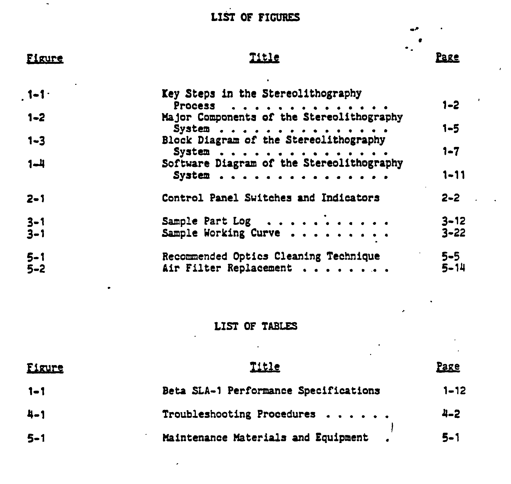


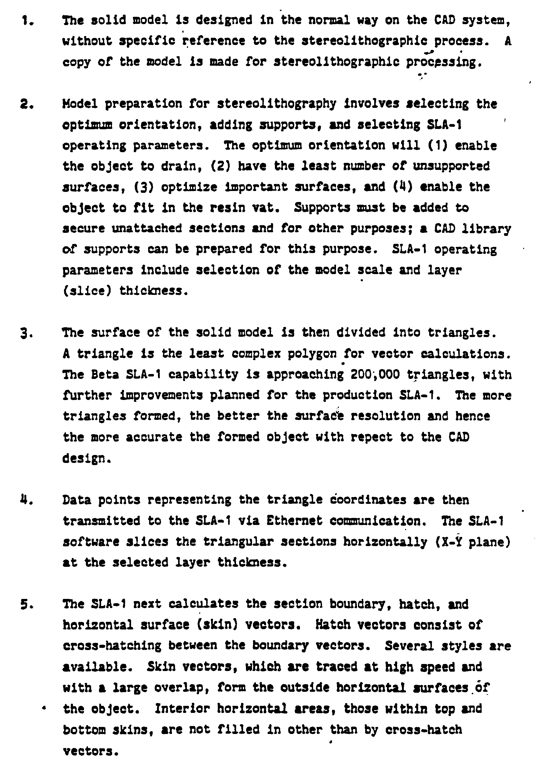


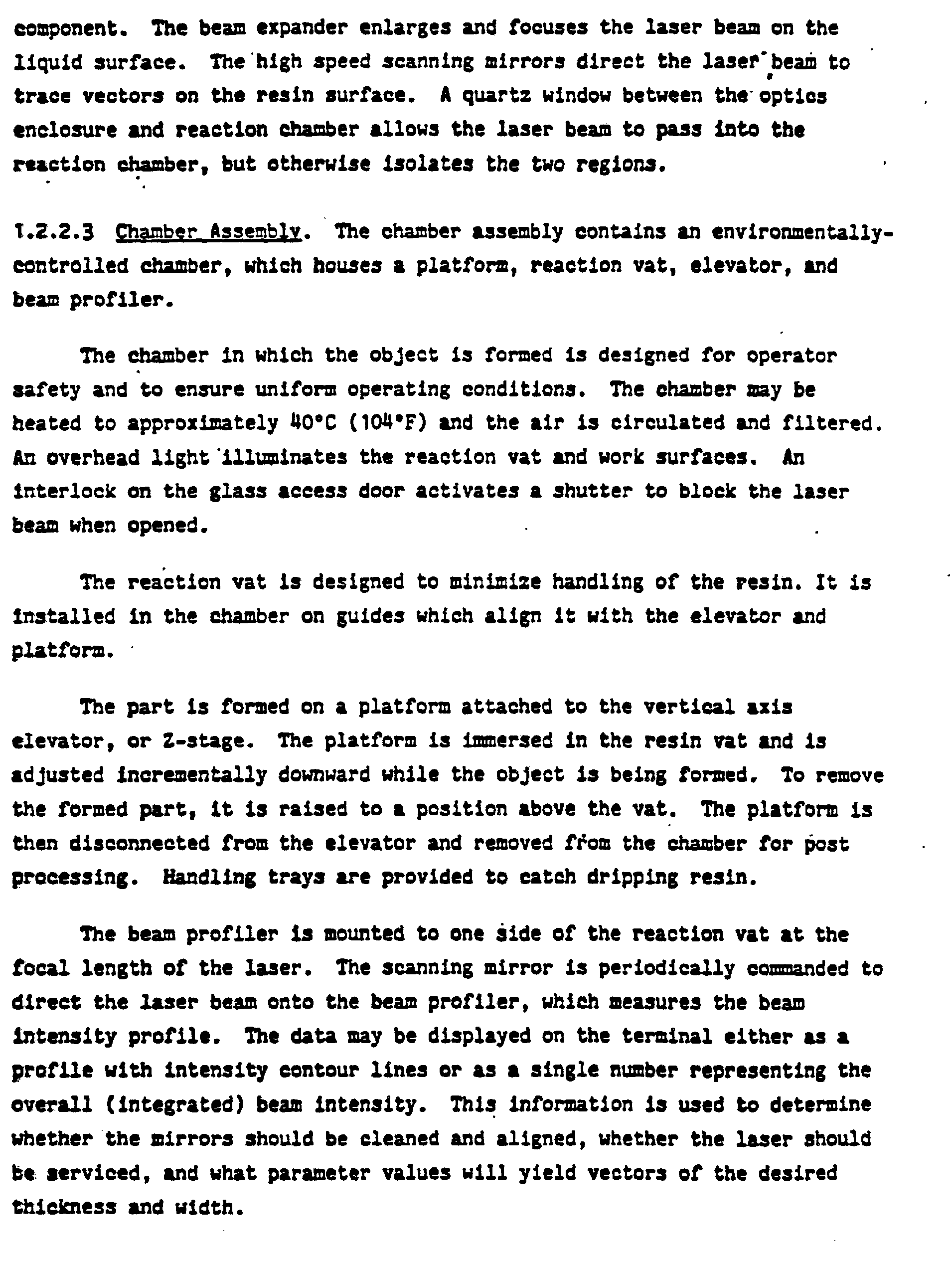


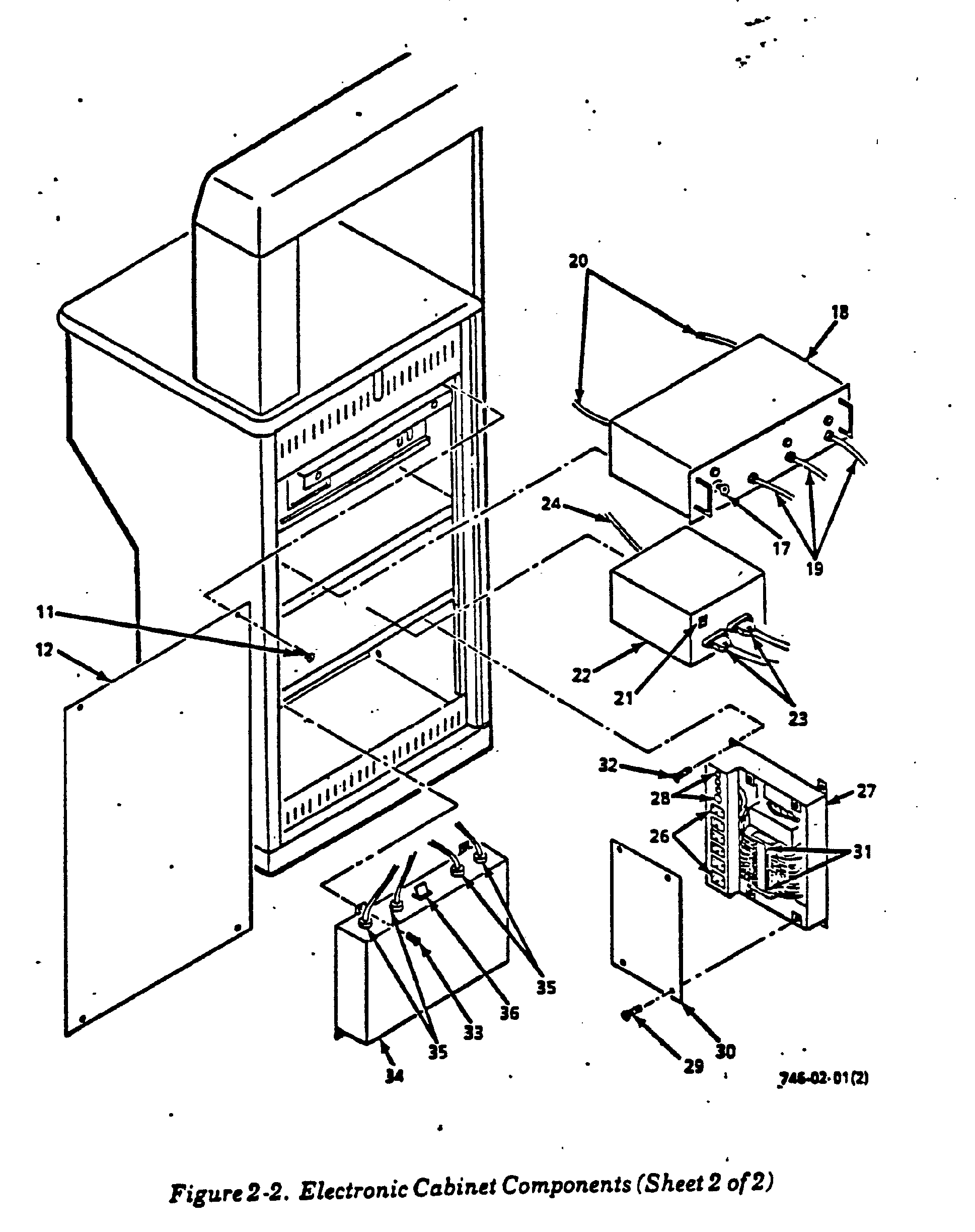


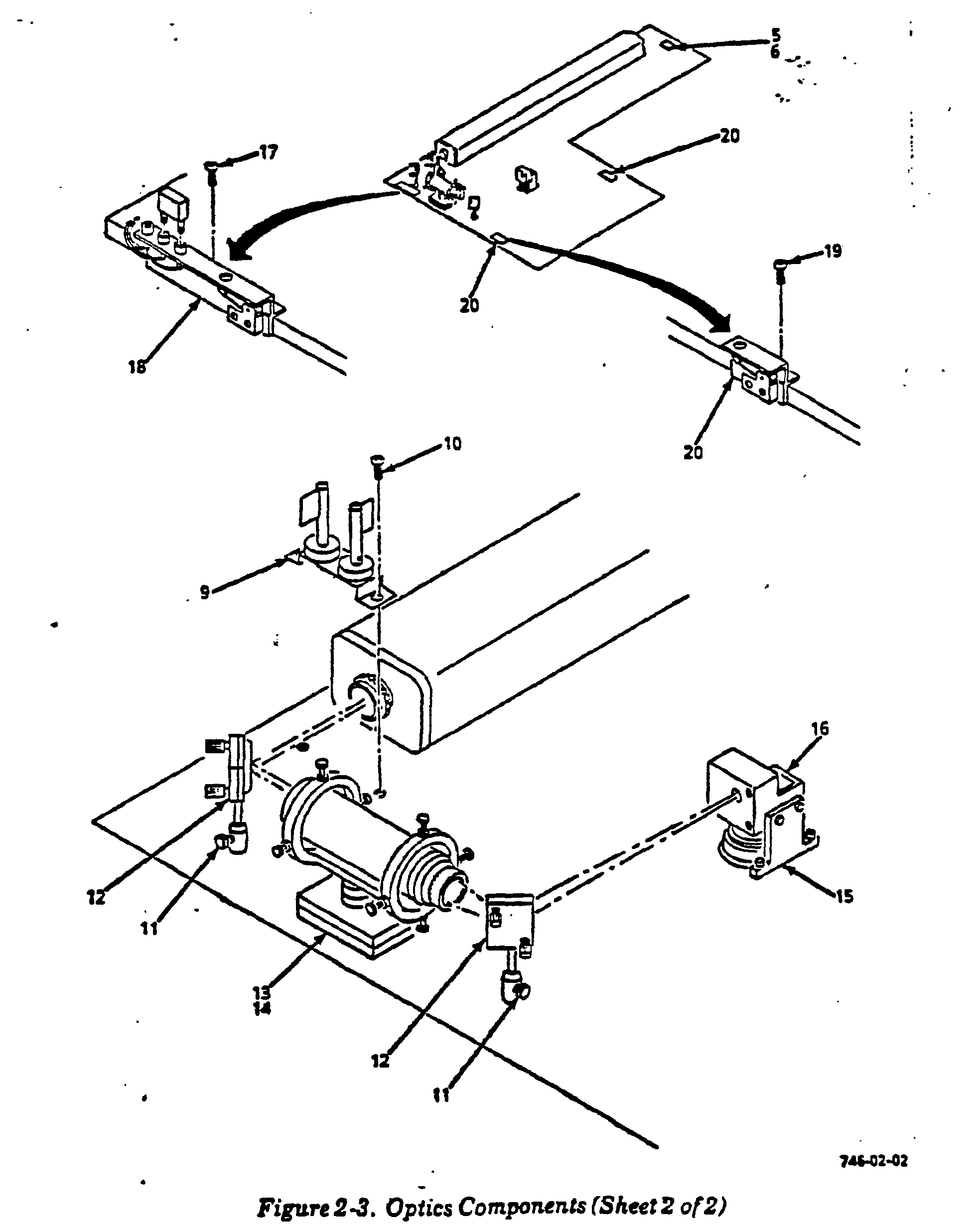


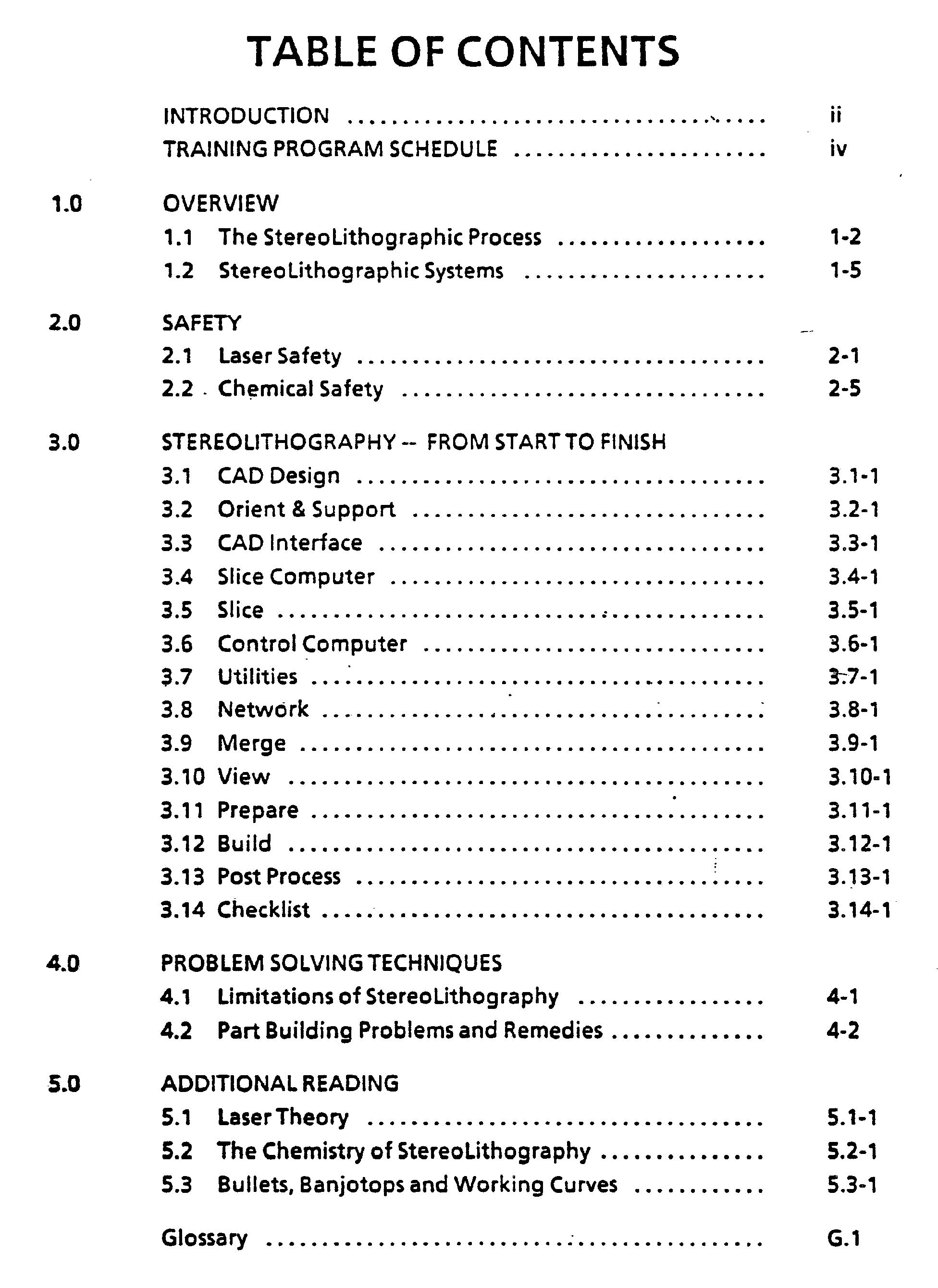


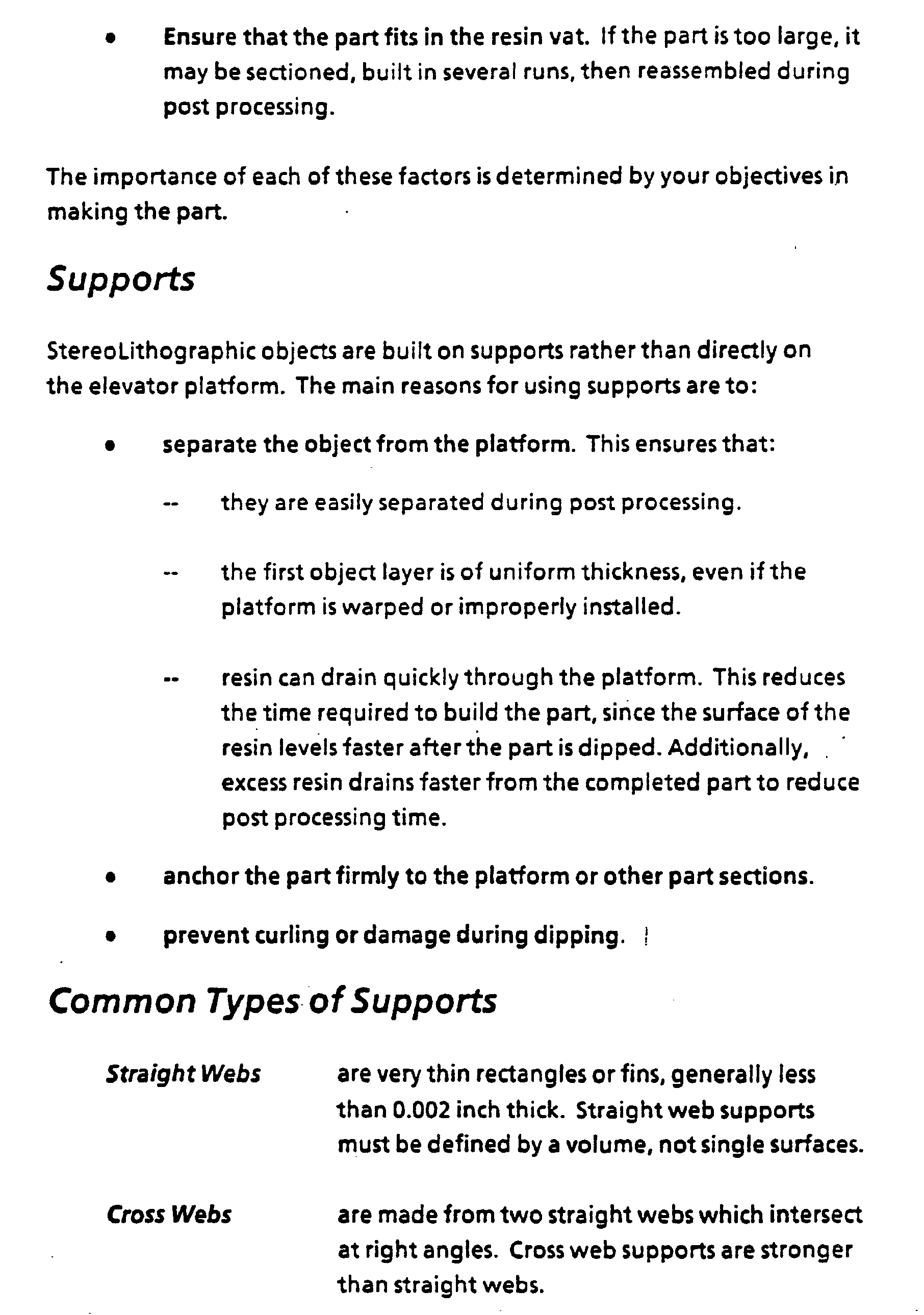


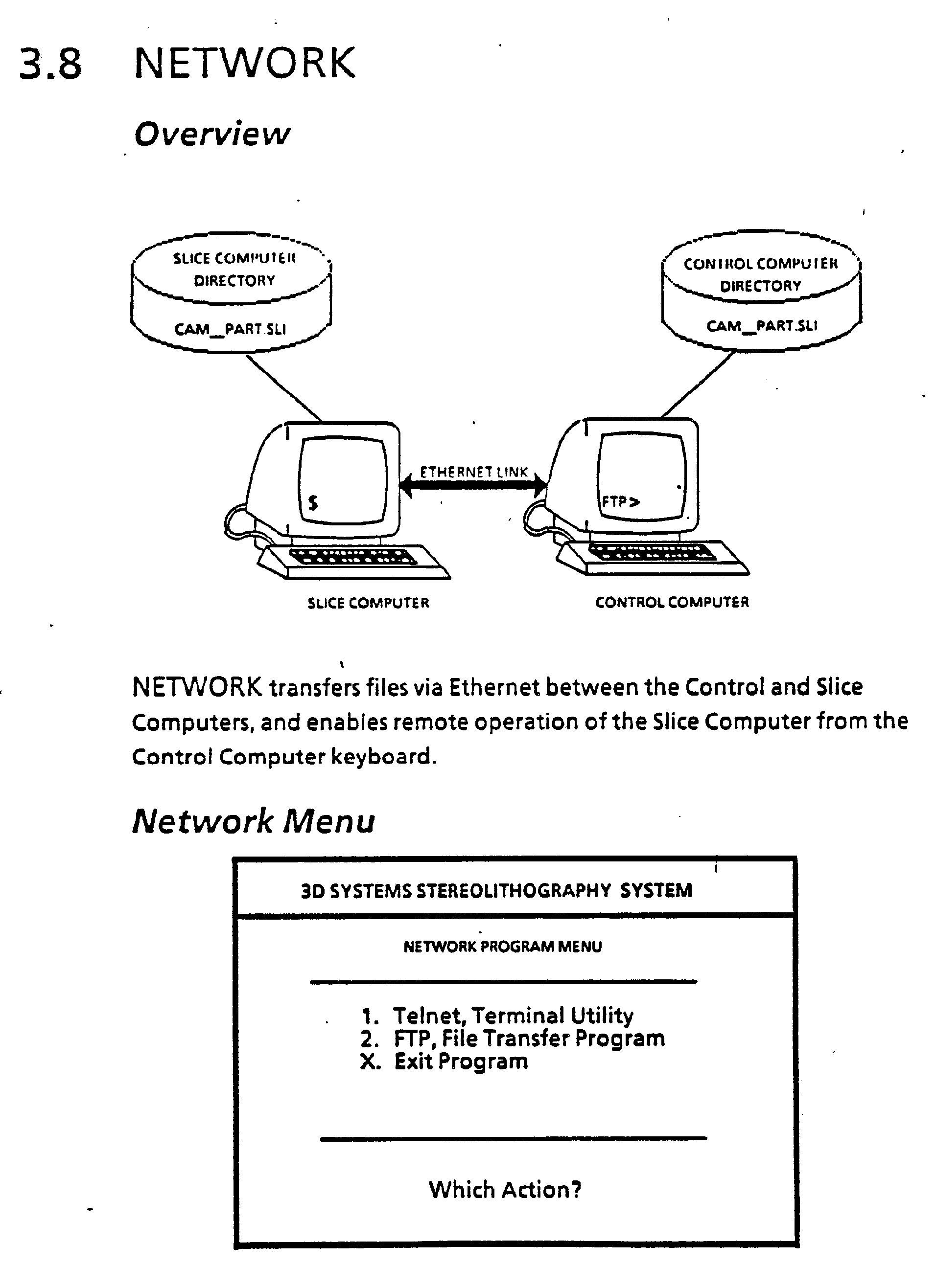


Claims (24)
Priority Applications (2)
| Application Number | Priority Date | Filing Date | Title |
|---|---|---|---|
| DE8916157U DE8916157U1 (en) | 1988-04-18 | 1989-04-17 | Stereolithographic supports |
| EP95111925A EP0686480B1 (en) | 1988-04-18 | 1989-04-17 | Stereolithographic supports |
Applications Claiming Priority (4)
| Application Number | Priority Date | Filing Date | Title |
|---|---|---|---|
| US182801 | 1988-04-18 | ||
| US07/182,801 US4999143A (en) | 1988-04-18 | 1988-04-18 | Methods and apparatus for production of three-dimensional objects by stereolithography |
| US26980188A | 1988-11-08 | 1988-11-08 | |
| US269801 | 1988-11-08 |
Related Child Applications (2)
| Application Number | Title | Priority Date | Filing Date |
|---|---|---|---|
| EP95111925.4 Division-Into | 1989-04-17 | ||
| EP95111925A Division EP0686480B1 (en) | 1988-04-18 | 1989-04-17 | Stereolithographic supports |
Publications (3)
| Publication Number | Publication Date |
|---|---|
| EP0338751A2 true EP0338751A2 (en) | 1989-10-25 |
| EP0338751A3 EP0338751A3 (en) | 1991-10-09 |
| EP0338751B1 EP0338751B1 (en) | 1996-03-20 |
Family
ID=26878432
Family Applications (2)
| Application Number | Title | Priority Date | Filing Date |
|---|---|---|---|
| EP95111925A Expired - Lifetime EP0686480B1 (en) | 1988-04-18 | 1989-04-17 | Stereolithographic supports |
| EP89303786A Expired - Lifetime EP0338751B1 (en) | 1988-04-18 | 1989-04-17 | Stereolithographic supports |
Family Applications Before (1)
| Application Number | Title | Priority Date | Filing Date |
|---|---|---|---|
| EP95111925A Expired - Lifetime EP0686480B1 (en) | 1988-04-18 | 1989-04-17 | Stereolithographic supports |
Country Status (8)
| Country | Link |
|---|---|
| EP (2) | EP0686480B1 (en) |
| JP (1) | JP3004302B2 (en) |
| KR (1) | KR100257135B1 (en) |
| AT (2) | ATE135622T1 (en) |
| DE (3) | DE338751T1 (en) |
| HK (2) | HK1001674A1 (en) |
| IL (1) | IL89978A0 (en) |
| WO (1) | WO1989010254A1 (en) |
Cited By (20)
| Publication number | Priority date | Publication date | Assignee | Title |
|---|---|---|---|---|
| EP0379067A2 (en) * | 1989-01-18 | 1990-07-25 | Mitsui Engineering and Shipbuilding Co, Ltd. | Optical molding method |
| EP0416124A1 (en) * | 1989-03-27 | 1991-03-13 | Sony Corporation | Method of forming three-dimensional shape |
| EP0436760A1 (en) * | 1989-12-18 | 1991-07-17 | Mitsui Engineering and Shipbuilding Co, Ltd. | Optical molding apparatus and movable base device therefor |
| DE4436695C1 (en) * | 1994-10-13 | 1995-12-21 | Eos Electro Optical Syst | Stereolithography, the making of a three dimensional object by irradiation of powder or liquid layers |
| BE1008128A3 (en) * | 1994-03-10 | 1996-01-23 | Materialise Nv | Method for supporting an object manufactured by stereo lithography or any rapid prototype manufacturing and method for manufacturing the taking used steunkonstruktie. |
| US5932059A (en) * | 1993-03-24 | 1999-08-03 | Eos Gmbh Optical Systems | Method for producing a three-dimensional object |
| US6558606B1 (en) * | 2000-01-28 | 2003-05-06 | 3D Systems, Inc. | Stereolithographic process of making a three-dimensional object |
| US7084370B2 (en) | 2002-05-03 | 2006-08-01 | Bego Medical Ag | Method for making products by freeform laser sintering |
| EP2022622A1 (en) * | 2007-08-10 | 2009-02-11 | Rolls-Royce plc | Support architecture |
| WO2012166953A1 (en) * | 2011-05-31 | 2012-12-06 | Nanoptics, Incorporated | Method and apparatus for lithographic manufacture of multi-component polymeric fiber plates |
| US8936602B2 (en) | 2000-03-17 | 2015-01-20 | Kinamed, Inc. | Marking template for installing a custom replacement device for resurfacing a femur and associated installation method |
| WO2015106836A1 (en) * | 2014-01-16 | 2015-07-23 | Hewlett-Packard Development Company, L.P. | Processing three-dimensional object data of an object to be generated by an additive manufacturing process |
| CN110142965A (en) * | 2019-05-17 | 2019-08-20 | 珠海赛纳打印科技股份有限公司 | Servo motor driving circuit and 3D printing device |
| US10538074B2 (en) * | 2014-01-16 | 2020-01-21 | Hewlett-Packard Development Company, L.P. | Processing slice data |
| US10558200B2 (en) | 2014-04-30 | 2020-02-11 | Hewlett-Packard Development Company, L.P. | Processing object data |
| US11203155B2 (en) | 2014-01-16 | 2021-12-21 | Hewlett-Packard Development Company, L.P. | Build material profile |
| US11618217B2 (en) | 2014-01-16 | 2023-04-04 | Hewlett-Packard Development Company, L.P. | Generating three-dimensional objects |
| US11673314B2 (en) | 2014-01-16 | 2023-06-13 | Hewlett-Packard Development Company, L.P. | Generating three-dimensional objects |
| US11679560B2 (en) | 2014-01-16 | 2023-06-20 | Hewlett-Packard Development Company, L.P. | Generating a three-dimensional object |
| WO2023154212A1 (en) * | 2022-02-11 | 2023-08-17 | NEXA3D Inc. | Compliant support structure for substratum used in photopolymerization vat |
Families Citing this family (37)
| Publication number | Priority date | Publication date | Assignee | Title |
|---|---|---|---|---|
| JPH0773884B2 (en) * | 1990-05-02 | 1995-08-09 | 三菱商事株式会社 | Light solidification modeling device |
| US5474719A (en) * | 1991-02-14 | 1995-12-12 | E. I. Du Pont De Nemours And Company | Method for forming solid objects utilizing viscosity reducible compositions |
| DE4125534A1 (en) * | 1991-08-01 | 1993-02-18 | Eos Electro Optical Syst | Three=dimensional layering - in which transparent sealed cover is used over bath to allow radiation through but exclude ambient atmos. |
| DE19954891A1 (en) * | 1999-11-15 | 2001-05-17 | Matthias Fockele | Making moldings and prototypes using stereo lithographic processes, employs rectangular or cubic cells in various fractional sizes for support, especially in overhung regions |
| GB2375988B (en) * | 2001-05-03 | 2004-05-26 | Peter David Hurley | 3-D bust maker |
| US7435072B2 (en) * | 2003-06-02 | 2008-10-14 | Hewlett-Packard Development Company, L.P. | Methods and systems for producing an object through solid freeform fabrication |
| DE102004032559B4 (en) * | 2004-07-06 | 2006-06-01 | Dr.Ing.H.C. F. Porsche Ag | Method for fixing and producing components, in particular vehicle components |
| US7997891B2 (en) * | 2007-04-12 | 2011-08-16 | Purdue Research Foundation | Molding processes and tool therefor |
| GB2458745B (en) * | 2008-02-13 | 2013-03-20 | Materials Solutions | A method of forming an article |
| US9789540B2 (en) | 2008-02-13 | 2017-10-17 | Materials Solutions Limited | Method of forming an article |
| CA2719737A1 (en) * | 2008-03-27 | 2009-10-01 | Iterations, Inc. | Three dimensional variable forming apparatus and methods of use thereof |
| CN102325644B (en) | 2008-12-22 | 2014-12-10 | 荷兰应用科学研究会(Tno) | Method and apparatus for layerwise production of a 3D object |
| EP2605898B1 (en) * | 2010-08-20 | 2020-09-30 | Zydex Pty Ltd | Apparatus and method for making an object |
| IT1403482B1 (en) * | 2011-01-18 | 2013-10-17 | Dws Srl | METHOD FOR THE PRODUCTION OF A THREE-DIMENSIONAL OBJECT AND A STEREOLITHOGRAPHIC MACHINE USING THIS METHOD |
| WO2012177900A1 (en) | 2011-06-22 | 2012-12-27 | Research Triangle Institute, International | Bipolar microelectronic device |
| US20140303942A1 (en) | 2013-04-05 | 2014-10-09 | Formlabs, Inc. | Additive fabrication support structures |
| DE102013218760A1 (en) * | 2013-09-19 | 2015-03-19 | Bayerische Motoren Werke Aktiengesellschaft | Method for producing a component in layers |
| TWI629162B (en) * | 2014-03-25 | 2018-07-11 | Dws有限責任公司 | Computer-implementted method, and equipment and computer program product for defining a supporting structure for a three-dimensional object to be made through stereolithography |
| KR20170023977A (en) | 2014-06-23 | 2017-03-06 | 카본, 인크. | Polyurethane resins having multiple mechanisms of hardening for use in producing three-dimensional objects |
| CN104118120B (en) * | 2014-07-10 | 2016-09-14 | 广州中国科学院先进技术研究所 | A kind of optical system printed for 3D and control method thereof |
| DE102014010412B4 (en) | 2014-07-14 | 2021-08-12 | Fraunhofer-Gesellschaft zur Förderung der angewandten Forschung e.V. | Process and arrangement for additive manufacturing of components |
| CN104482882A (en) * | 2014-12-22 | 2015-04-01 | 河海大学 | Break opening measuring instrument used in overtopping dam break tests and measuring method |
| US10563292B2 (en) | 2015-04-09 | 2020-02-18 | Electronics And Telecommunications Research Institute | Metal material for 3-dimensional printing, method for manufacturing the same, and method for 3-dimensional printing using the same |
| US10612112B2 (en) | 2015-04-09 | 2020-04-07 | Electronics And Telecommunications Research Institute | Noble metal material for 3-dimensional printing, method for manufacturing the same, and method for 3-dimensional printing using the same |
| WO2016198291A1 (en) | 2015-06-09 | 2016-12-15 | Politecnico Di Milano | A device for direct additive manufacturing by means of extrusion of metal powders and ceramic materials on a parallel kinematic table |
| EP3368235A4 (en) | 2015-10-30 | 2019-07-03 | Seurat Technologies, Inc. | Chamber systems for additive manufacturing |
| CN107042629A (en) * | 2016-02-05 | 2017-08-15 | 新会江裕信息产业有限公司 | Three-dimensional printing method |
| CN107053651B (en) * | 2016-02-05 | 2019-07-12 | 三纬国际立体列印科技股份有限公司 | Three dimensional model printing cuts layer method |
| US10799951B2 (en) | 2016-02-11 | 2020-10-13 | General Electric Company | Method and conformal supports for additive manufacturing |
| US10583647B2 (en) | 2017-05-17 | 2020-03-10 | Ford Motor Company | Method of controlling warping in 3D printing |
| EP3720685A1 (en) | 2017-12-08 | 2020-10-14 | 3M Innovative Properties Company | Method and apparatus for 3d-printing gels |
| US20210122116A1 (en) * | 2018-07-05 | 2021-04-29 | Mitsui Chemicals, Inc. | Three-dimensional modeling apparatus, control apparatus, and method for manufacturing modeled object |
| CN109465445B (en) * | 2018-11-12 | 2020-12-01 | 成都飞机工业(集团)有限责任公司 | Method for weakening residual stress of 3D printed part based on aluminum matrix composite |
| KR102117592B1 (en) * | 2019-08-13 | 2020-06-02 | 원광이엔텍 주식회사 | Apparatus and method for integrated processing of modeling files for 3D printers |
| CN110802837A (en) * | 2019-10-31 | 2020-02-18 | 共享智能装备有限公司 | FDM printing product supporting structure and printing method |
| KR102338498B1 (en) * | 2020-11-25 | 2021-12-13 | 한국전자기술연구원 | Method for making assistant support for 3D printing output stability |
| CN112873838B (en) * | 2021-02-02 | 2022-04-05 | 中山大学 | Biological ink printing condition screening platform and screening method |
Citations (5)
| Publication number | Priority date | Publication date | Assignee | Title |
|---|---|---|---|---|
| US4041476A (en) | 1971-07-23 | 1977-08-09 | Wyn Kelly Swainson | Method, medium and apparatus for producing three-dimensional figure product |
| US4078229A (en) | 1975-01-27 | 1978-03-07 | Swanson Wyn K | Three dimensional systems |
| US4238840A (en) | 1967-07-12 | 1980-12-09 | Formigraphic Engine Corporation | Method, medium and apparatus for producing three dimensional figure product |
| US4288861A (en) | 1977-12-01 | 1981-09-08 | Formigraphic Engine Corporation | Three-dimensional systems |
| US4575330A (en) | 1984-08-08 | 1986-03-11 | Uvp, Inc. | Apparatus for production of three-dimensional objects by stereolithography |
Family Cites Families (4)
| Publication number | Priority date | Publication date | Assignee | Title |
|---|---|---|---|---|
| US2775758A (en) * | 1951-05-25 | 1956-12-25 | Munz Otto John | Photo-glyph recording |
| JPS60247515A (en) * | 1984-05-23 | 1985-12-07 | Oosakafu | Optical shaping method |
| DE3750709T2 (en) * | 1986-06-03 | 1995-03-16 | Cubital Ltd | Device for developing three-dimensional models. |
| JPH02251419A (en) * | 1989-03-27 | 1990-10-09 | Sony Corp | Three-dimensional shape formation |
-
1989
- 1989-04-17 WO PCT/US1989/001557 patent/WO1989010254A1/en active Application Filing
- 1989-04-17 AT AT89303786T patent/ATE135622T1/en not_active IP Right Cessation
- 1989-04-17 DE DE0338751T patent/DE338751T1/en active Pending
- 1989-04-17 AT AT95111925T patent/ATE209562T1/en not_active IP Right Cessation
- 1989-04-17 EP EP95111925A patent/EP0686480B1/en not_active Expired - Lifetime
- 1989-04-17 IL IL89978A patent/IL89978A0/en not_active IP Right Cessation
- 1989-04-17 EP EP89303786A patent/EP0338751B1/en not_active Expired - Lifetime
- 1989-04-17 KR KR1019890702385A patent/KR100257135B1/en not_active IP Right Cessation
- 1989-04-17 DE DE68925989T patent/DE68925989T2/en not_active Expired - Lifetime
- 1989-04-17 DE DE68929352T patent/DE68929352T2/en not_active Expired - Lifetime
- 1989-04-17 JP JP1505840A patent/JP3004302B2/en not_active Expired - Lifetime
-
1998
- 1998-01-22 HK HK98100599A patent/HK1001674A1/en not_active IP Right Cessation
- 1998-06-17 HK HK98105545A patent/HK1006793A1/en not_active IP Right Cessation
Patent Citations (6)
| Publication number | Priority date | Publication date | Assignee | Title |
|---|---|---|---|---|
| US4238840A (en) | 1967-07-12 | 1980-12-09 | Formigraphic Engine Corporation | Method, medium and apparatus for producing three dimensional figure product |
| US4041476A (en) | 1971-07-23 | 1977-08-09 | Wyn Kelly Swainson | Method, medium and apparatus for producing three-dimensional figure product |
| US4078229A (en) | 1975-01-27 | 1978-03-07 | Swanson Wyn K | Three dimensional systems |
| US4288861A (en) | 1977-12-01 | 1981-09-08 | Formigraphic Engine Corporation | Three-dimensional systems |
| US4575330A (en) | 1984-08-08 | 1986-03-11 | Uvp, Inc. | Apparatus for production of three-dimensional objects by stereolithography |
| US4575330B1 (en) | 1984-08-08 | 1989-12-19 |
Non-Patent Citations (1)
| Title |
|---|
| "Understanding PHIGS", TEMPLATE, MEGATEK CORP. |
Cited By (35)
| Publication number | Priority date | Publication date | Assignee | Title |
|---|---|---|---|---|
| EP0379067A3 (en) * | 1989-01-18 | 1990-11-22 | Mitsui Engineering and Shipbuilding Co, Ltd. | Optical molding method |
| US5089184A (en) * | 1989-01-18 | 1992-02-18 | Mitsui Engineering And Shipbuilding Co., Ltd. | Optical molding method |
| EP0379067A2 (en) * | 1989-01-18 | 1990-07-25 | Mitsui Engineering and Shipbuilding Co, Ltd. | Optical molding method |
| EP0416124A1 (en) * | 1989-03-27 | 1991-03-13 | Sony Corporation | Method of forming three-dimensional shape |
| EP0416124A4 (en) * | 1989-03-27 | 1991-10-02 | Sony Corporation | Method of forming three-dimensional shape |
| EP0436760A1 (en) * | 1989-12-18 | 1991-07-17 | Mitsui Engineering and Shipbuilding Co, Ltd. | Optical molding apparatus and movable base device therefor |
| US5932059A (en) * | 1993-03-24 | 1999-08-03 | Eos Gmbh Optical Systems | Method for producing a three-dimensional object |
| US5595703A (en) * | 1994-03-10 | 1997-01-21 | Materialise, Naamloze Vennootschap | Method for supporting an object made by means of stereolithography or another rapid prototype production method |
| DE19507881B4 (en) * | 1994-03-10 | 2006-11-23 | Materialise N.V. | Method of supporting an object made by stereolithography or another rapid prototype manufacturing method |
| BE1008128A3 (en) * | 1994-03-10 | 1996-01-23 | Materialise Nv | Method for supporting an object manufactured by stereo lithography or any rapid prototype manufacturing and method for manufacturing the taking used steunkonstruktie. |
| DE19538257A1 (en) * | 1994-10-13 | 1996-04-18 | Eos Electro Optical Syst | Stereo:lithographic prodn. of three dimensional object and easily detached support |
| US5897825A (en) * | 1994-10-13 | 1999-04-27 | 3D Systems, Inc. | Method for producing a three-dimensional object |
| WO1996011790A1 (en) * | 1994-10-13 | 1996-04-25 | Eos Gmbh Electro Optical Systems | Process for manufacturing three-dimensional objects |
| DE4436695C1 (en) * | 1994-10-13 | 1995-12-21 | Eos Electro Optical Syst | Stereolithography, the making of a three dimensional object by irradiation of powder or liquid layers |
| US6558606B1 (en) * | 2000-01-28 | 2003-05-06 | 3D Systems, Inc. | Stereolithographic process of making a three-dimensional object |
| US6797351B2 (en) | 2000-01-28 | 2004-09-28 | 3D Systems, Inc. | Stereolithographic supports |
| US8936602B2 (en) | 2000-03-17 | 2015-01-20 | Kinamed, Inc. | Marking template for installing a custom replacement device for resurfacing a femur and associated installation method |
| US8936601B2 (en) | 2000-03-17 | 2015-01-20 | Kinamed, Inc. | Marking template for installing a custom replacement device for resurfacing a femur and associated installation method |
| US9393032B2 (en) | 2000-03-17 | 2016-07-19 | Kinamed, Inc. | Marking template for installing a custom replacement device for resurfacing a femur and associated installation method |
| US7084370B2 (en) | 2002-05-03 | 2006-08-01 | Bego Medical Ag | Method for making products by freeform laser sintering |
| US7381921B2 (en) | 2002-05-03 | 2008-06-03 | Bego Medical Gmbh | Method for making products by freeform laser sintering |
| EP2022622A1 (en) * | 2007-08-10 | 2009-02-11 | Rolls-Royce plc | Support architecture |
| WO2012166953A1 (en) * | 2011-05-31 | 2012-12-06 | Nanoptics, Incorporated | Method and apparatus for lithographic manufacture of multi-component polymeric fiber plates |
| US20160082666A1 (en) * | 2014-01-16 | 2016-03-24 | Alejandro Manuel De Pena | Processing object data |
| WO2015106836A1 (en) * | 2014-01-16 | 2015-07-23 | Hewlett-Packard Development Company, L.P. | Processing three-dimensional object data of an object to be generated by an additive manufacturing process |
| US10137644B2 (en) * | 2014-01-16 | 2018-11-27 | Hewlett-Packard Development Company, L.P. | Processing object data |
| US10317882B2 (en) | 2014-01-16 | 2019-06-11 | Hewlett-Packard Development Company, L.P. | Processing object data |
| US10538074B2 (en) * | 2014-01-16 | 2020-01-21 | Hewlett-Packard Development Company, L.P. | Processing slice data |
| US11203155B2 (en) | 2014-01-16 | 2021-12-21 | Hewlett-Packard Development Company, L.P. | Build material profile |
| US11618217B2 (en) | 2014-01-16 | 2023-04-04 | Hewlett-Packard Development Company, L.P. | Generating three-dimensional objects |
| US11673314B2 (en) | 2014-01-16 | 2023-06-13 | Hewlett-Packard Development Company, L.P. | Generating three-dimensional objects |
| US11679560B2 (en) | 2014-01-16 | 2023-06-20 | Hewlett-Packard Development Company, L.P. | Generating a three-dimensional object |
| US10558200B2 (en) | 2014-04-30 | 2020-02-11 | Hewlett-Packard Development Company, L.P. | Processing object data |
| CN110142965A (en) * | 2019-05-17 | 2019-08-20 | 珠海赛纳打印科技股份有限公司 | Servo motor driving circuit and 3D printing device |
| WO2023154212A1 (en) * | 2022-02-11 | 2023-08-17 | NEXA3D Inc. | Compliant support structure for substratum used in photopolymerization vat |
Also Published As
| Publication number | Publication date |
|---|---|
| JP3004302B2 (en) | 2000-01-31 |
| EP0686480A2 (en) | 1995-12-13 |
| JPH04506778A (en) | 1992-11-26 |
| DE68925989D1 (en) | 1996-04-25 |
| HK1006793A1 (en) | 1999-03-19 |
| DE68929352D1 (en) | 2002-01-10 |
| DE68925989T2 (en) | 1996-12-05 |
| KR100257135B1 (en) | 2000-06-01 |
| EP0338751A3 (en) | 1991-10-09 |
| ATE135622T1 (en) | 1996-04-15 |
| EP0686480A3 (en) | 1996-11-20 |
| IL89978A0 (en) | 1989-12-15 |
| HK1001674A1 (en) | 2003-07-10 |
| WO1989010254A1 (en) | 1989-11-02 |
| DE68929352T2 (en) | 2002-09-19 |
| KR900700273A (en) | 1990-08-13 |
| DE338751T1 (en) | 1996-01-04 |
| EP0338751B1 (en) | 1996-03-20 |
| EP0686480B1 (en) | 2001-11-28 |
| ATE209562T1 (en) | 2001-12-15 |
Similar Documents
| Publication | Publication Date | Title |
|---|---|---|
| US4999143A (en) | Methods and apparatus for production of three-dimensional objects by stereolithography | |
| EP0338751B1 (en) | Stereolithographic supports | |
| US5015424A (en) | Methods and apparatus for production of three-dimensional objects by stereolithography | |
| US5571471A (en) | Method of production of three-dimensional objects by stereolithography | |
| US4996010A (en) | Methods and apparatus for production of three-dimensional objects by stereolithography | |
| US5059359A (en) | Methods and apparatus for production of three-dimensional objects by stereolithography | |
| US5236637A (en) | Method of and apparatus for production of three dimensional objects by stereolithography | |
| CA1338521C (en) | Cad/cam stereolithographic data conversion | |
| US5772947A (en) | Stereolithographic curl reduction | |
| US5174943A (en) | Method for production of three-dimensional objects by stereolithography | |
| US5344298A (en) | Apparatus for making three-dimensional objects by stereolithography | |
| US5137662A (en) | Method and apparatus for production of three-dimensional objects by stereolithography | |
| US4929402A (en) | Method for production of three-dimensional objects by stereolithography | |
| US5184307A (en) | Method and apparatus for production of high resolution three-dimensional objects by stereolithography | |
| EP0171069B1 (en) | Method and apparatus for production of three-dimensional objects by stereolithography | |
| US5104592A (en) | Method of and apparatus for production of three-dimensional objects by stereolithography with reduced curl | |
| US5273691A (en) | Stereolithographic curl reduction | |
| US5076974A (en) | Methods of curing partially polymerized parts | |
| CA1339751C (en) | Stereolithographic supports |
Legal Events
| Date | Code | Title | Description |
|---|---|---|---|
| PUAI | Public reference made under article 153(3) epc to a published international application that has entered the european phase |
Free format text: ORIGINAL CODE: 0009012 |
|
| AK | Designated contracting states |
Kind code of ref document: A2 Designated state(s): AT BE CH DE ES FR GB GR IT LI LU NL SE |
|
| PUAL | Search report despatched |
Free format text: ORIGINAL CODE: 0009013 |
|
| AK | Designated contracting states |
Kind code of ref document: A3 Designated state(s): AT BE CH DE ES FR GB GR IT LI LU NL SE |
|
| RHK1 | Main classification (correction) |
Ipc: B29C 39/42 |
|
| 17P | Request for examination filed |
Effective date: 19920324 |
|
| 17Q | First examination report despatched |
Effective date: 19930809 |
|
| EL | Fr: translation of claims filed | ||
| DET | De: translation of patent claims | ||
| GRAA | (expected) grant |
Free format text: ORIGINAL CODE: 0009210 |
|
| AK | Designated contracting states |
Kind code of ref document: B1 Designated state(s): AT BE CH DE ES FR GB GR IT LI LU NL SE |
|
| PG25 | Lapsed in a contracting state [announced via postgrant information from national office to epo] |
Ref country code: GR Free format text: LAPSE BECAUSE OF FAILURE TO SUBMIT A TRANSLATION OF THE DESCRIPTION OR TO PAY THE FEE WITHIN THE PRESCRIBED TIME-LIMIT Effective date: 19960320 Ref country code: AT Effective date: 19960320 Ref country code: ES Free format text: THE PATENT HAS BEEN ANNULLED BY A DECISION OF A NATIONAL AUTHORITY Effective date: 19960320 Ref country code: NL Free format text: LAPSE BECAUSE OF FAILURE TO SUBMIT A TRANSLATION OF THE DESCRIPTION OR TO PAY THE FEE WITHIN THE PRESCRIBED TIME-LIMIT Effective date: 19960320 |
|
| REF | Corresponds to: |
Ref document number: 135622 Country of ref document: AT Date of ref document: 19960415 Kind code of ref document: T |
|
| XX | Miscellaneous (additional remarks) |
Free format text: TEILANMELDUNG 95111925.4 EINGEREICHT AM 28/07/95. |
|
| REF | Corresponds to: |
Ref document number: 68925989 Country of ref document: DE Date of ref document: 19960425 |
|
| ITF | It: translation for a ep patent filed |
Owner name: JACOBACCI & PERANI S.P.A. |
|
| PG25 | Lapsed in a contracting state [announced via postgrant information from national office to epo] |
Ref country code: SE Effective date: 19960620 |
|
| ET | Fr: translation filed | ||
| REG | Reference to a national code |
Ref country code: CH Ref legal event code: NV Representative=s name: HEPP, WENGER & RYFFEL AG |
|
| NLV1 | Nl: lapsed or annulled due to failure to fulfill the requirements of art. 29p and 29m of the patents act | ||
| 111L | Licence recorded |
Free format text: 950725 0100 3D SYSTEMS FRANCE, SARL |
|
| PLBI | Opposition filed |
Free format text: ORIGINAL CODE: 0009260 |
|
| PLBQ | Unpublished change to opponent data |
Free format text: ORIGINAL CODE: EPIDOS OPPO |
|
| PLBF | Reply of patent proprietor to notice(s) of opposition |
Free format text: ORIGINAL CODE: EPIDOS OBSO |
|
| 26 | Opposition filed |
Opponent name: EOS GMBH ELECTRO OPTICAL SYSTEMS Effective date: 19961219 |
|
| PLBF | Reply of patent proprietor to notice(s) of opposition |
Free format text: ORIGINAL CODE: EPIDOS OBSO |
|
| PLBF | Reply of patent proprietor to notice(s) of opposition |
Free format text: ORIGINAL CODE: EPIDOS OBSO |
|
| PLBL | Opposition procedure terminated |
Free format text: ORIGINAL CODE: EPIDOS OPPC |
|
| PLBM | Termination of opposition procedure: date of legal effect published |
Free format text: ORIGINAL CODE: 0009276 |
|
| STAA | Information on the status of an ep patent application or granted ep patent |
Free format text: STATUS: OPPOSITION PROCEDURE CLOSED |
|
| 27C | Opposition proceedings terminated |
Effective date: 19971205 |
|
| PGFP | Annual fee paid to national office [announced via postgrant information from national office to epo] |
Ref country code: LU Payment date: 19990422 Year of fee payment: 11 |
|
| PG25 | Lapsed in a contracting state [announced via postgrant information from national office to epo] |
Ref country code: LU Free format text: LAPSE BECAUSE OF NON-PAYMENT OF DUE FEES Effective date: 20000417 |
|
| REG | Reference to a national code |
Ref country code: GB Ref legal event code: IF02 |
|
| PGFP | Annual fee paid to national office [announced via postgrant information from national office to epo] |
Ref country code: CH Payment date: 20020422 Year of fee payment: 14 |
|
| PG25 | Lapsed in a contracting state [announced via postgrant information from national office to epo] |
Ref country code: LI Free format text: LAPSE BECAUSE OF NON-PAYMENT OF DUE FEES Effective date: 20030430 Ref country code: CH Free format text: LAPSE BECAUSE OF NON-PAYMENT OF DUE FEES Effective date: 20030430 |
|
| REG | Reference to a national code |
Ref country code: CH Ref legal event code: PL |
|
| PGFP | Annual fee paid to national office [announced via postgrant information from national office to epo] |
Ref country code: DE Payment date: 20080424 Year of fee payment: 20 Ref country code: FR Payment date: 20080312 Year of fee payment: 20 |
|
| PGFP | Annual fee paid to national office [announced via postgrant information from national office to epo] |
Ref country code: IT Payment date: 20080428 Year of fee payment: 20 Ref country code: BE Payment date: 20080616 Year of fee payment: 20 |
|
| PGFP | Annual fee paid to national office [announced via postgrant information from national office to epo] |
Ref country code: GB Payment date: 20080423 Year of fee payment: 20 |
|
| BE20 | Be: patent expired |
Owner name: *3D SYSTEMS INC. Effective date: 20090417 |
|
| REG | Reference to a national code |
Ref country code: GB Ref legal event code: PE20 Expiry date: 20090416 |
|
| REG | Reference to a national code |
Ref country code: FR Ref legal event code: CA |
|
| PG25 | Lapsed in a contracting state [announced via postgrant information from national office to epo] |
Ref country code: GB Free format text: LAPSE BECAUSE OF EXPIRATION OF PROTECTION Effective date: 20090416 |