EP0337501A2 - Thermal printing - Google Patents
Thermal printing Download PDFInfo
- Publication number
- EP0337501A2 EP0337501A2 EP89109542A EP89109542A EP0337501A2 EP 0337501 A2 EP0337501 A2 EP 0337501A2 EP 89109542 A EP89109542 A EP 89109542A EP 89109542 A EP89109542 A EP 89109542A EP 0337501 A2 EP0337501 A2 EP 0337501A2
- Authority
- EP
- European Patent Office
- Prior art keywords
- ribbon
- cassette
- spool
- article
- print head
- Prior art date
- Legal status (The legal status is an assumption and is not a legal conclusion. Google has not performed a legal analysis and makes no representation as to the accuracy of the status listed.)
- Granted
Links
Images


Classifications
-
- B—PERFORMING OPERATIONS; TRANSPORTING
- B41—PRINTING; LINING MACHINES; TYPEWRITERS; STAMPS
- B41J—TYPEWRITERS; SELECTIVE PRINTING MECHANISMS, i.e. MECHANISMS PRINTING OTHERWISE THAN FROM A FORME; CORRECTION OF TYPOGRAPHICAL ERRORS
- B41J33/00—Apparatus or arrangements for feeding ink ribbons or like character-size impression-transfer material
- B41J33/14—Ribbon-feed devices or mechanisms
-
- B—PERFORMING OPERATIONS; TRANSPORTING
- B41—PRINTING; LINING MACHINES; TYPEWRITERS; STAMPS
- B41J—TYPEWRITERS; SELECTIVE PRINTING MECHANISMS, i.e. MECHANISMS PRINTING OTHERWISE THAN FROM A FORME; CORRECTION OF TYPOGRAPHICAL ERRORS
- B41J32/00—Ink-ribbon cartridges
-
- B—PERFORMING OPERATIONS; TRANSPORTING
- B41—PRINTING; LINING MACHINES; TYPEWRITERS; STAMPS
- B41J—TYPEWRITERS; SELECTIVE PRINTING MECHANISMS, i.e. MECHANISMS PRINTING OTHERWISE THAN FROM A FORME; CORRECTION OF TYPOGRAPHICAL ERRORS
- B41J35/00—Other apparatus or arrangements associated with, or incorporated in, ink-ribbon mechanisms
- B41J35/28—Detachable carriers or holders for ink-ribbon mechanisms
-
- G—PHYSICS
- G07—CHECKING-DEVICES
- G07B—TICKET-ISSUING APPARATUS; FARE-REGISTERING APPARATUS; FRANKING APPARATUS
- G07B17/00—Franking apparatus
- G07B17/00185—Details internally of apparatus in a franking system, e.g. franking machine at customer or apparatus at post office
- G07B17/00193—Constructional details of apparatus in a franking system
- G07B2017/0025—Storage of, e.g. ribbon
Definitions
- This invention relates to a method of and apparatus for printing using a thermal print head.
- Cassettes containing a spool of ribbon in which during use, the ribbon is transferred to another spool are known. They are employed in tape recoders, typewriters, printers and so on to carry items such as magnetic tape or inked ribbon. These cassettes usually have features, such as sprocketed holes in the centre of one or both of the spools, which allow the apparatus on which the cassette is to be used, to transmit a driving force to the cassette which will wind the used ribbon onto the take-up spool.
- the mechanisms used in such arrangements are complex and a motor or other prime mover is required to power the drive mechanism.
- This prime mover may be synchronised with the take-up spool speed requirements or, as is more often the case, a slipping clutch is used to automatically control the speed of take-up.
- the cassette must he designed so that the drive mechanism will readily engage the cassette. This is usually simplified by allowing the spools to 'float' within the cassette. The spools can then align themselves with the drive mechanism as the cassette is inserted.
- a still more complex arrangement is necessary if the cassette is to be inserted into the apparatus in a direction other than parallel to the axes of rotation of the spools. It may then be necessary to use an arrangement in which the drive mechanism is moved into engagement with the cassette spools after the cassette has been fully inserted.
- a method of printing using a thermal print head and a ribbon of thermally activatable dye comprising the steps of producing relative movement between the print head on the one hand and the article to be printed and the ribbon on the other hand, wherein adhesion between the article and the ribbon is created by local heating of the ribbon and is used to effect drive of the ribbon past the print head from a supply spool to a take-up spool.
- the spools may be located in a cassette.
- the invention thus enables a cassette to be used, and obviates the need for an external drive to the take-up spool. Instead the ribbon is pulled from the supply spool and the motion thus generated in the supply spool may be transmitted via a slipping drive arrangement to the takeup spool.
- the thermally activatable dye is carried on the ribbon and after thermal activation, this dye has been found to provide an adhesive force between the ribbon and the printed item which is sufficient to case the ribbon to be unwound from the supply spool when drive is provided only to the printed item. Thus no drive force at all need be provided directly to the ribbon or cassette, only to the item that is being printed.
- An additional advantage of the method of the invention when used with thermal transfer printing apparatus is that it allows lateral movement of the cassette during insertion. Such a feature is used to advantage in two areas: (a) to reduce the chances of the ribbon snagging on the print head and (b) to allow the ribbon inside the cassette to engage with a drive to a sensor for detecting the motion of the ribbon (and therefor the article being printed).
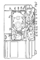
- the franking machine is shown pictorially in Figure 1 and includes a keyboard 10 for data entry and LED display devices 12 and 14 for displaying information which is to be printed during the franking operations.
- a printing ribbon cassette is received in a compartment 16 which has a door 18 which is openable to allow a cassette to be inserted so that the ribbon underlies a thermal printing head located within the machine is located (see item 27 in Figure 2) and which extends into the housing 16 to cooperate with the ribbon housed within the cassette (as will hereinafter be described), in order toprint information on to an envelope or like article which is inserted in the direction of the arrow 20, beneath the cassette compartment.
- the franked envelope emerges from the other side of the compartment as indicated by the arrow 22.
- the expression inked ribbon is intended to cover any dye coated or impregnated ribbon or tape, which dye can be deposited onto sheet material in contact therewith.
- the printing head forms no part of the present invention but will be described in general so as to provide a more complete understanding of the overall operation of the machine.
- the printer is made up of one or more rows of points which can be individually electrically heated and which are selectively activated in timed relationship to the transport of the envelope relative to the printer.
- the heated points are commonly referred to as "thermal points”.
- thermal points By sandwiching a dye coated or impregnated ribbon between the thermal points and an envelope, so printing onto the envelope can be achieved by selectively activating the thermal points so as to locally heat the ribbon and cause dye to be transferred at the heated point from the ribbon to the envelope surface.
- the thermal printing step can produce sufficient adhesion between the ribbon and the envelope, to allow the movement of the latter to effect ribbon feed. This automatically ensures the required synchronism between envelope movement and ribbon movement.
- the ribbon is automatically peeled away from the envelope surface by causing the paths of the envelope and the ribbon to diverge.
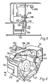
- the cassette (best seen in Figure 6) comprises an outer casing 24 shaped to allow it to be fitted into the housing 16 in the direction of the arrow 26 of Figure 6.
- a latch mechanism (to be described later) operates so as to lift the cassette into an elevated position as can best be seen in Figure 2, where the cassette is shown in its operating position within the housing.
- the lower section of the cassette carriage 24 is cut away at 25 to allow the casing to fit over the printing head 27 with the inked ribbon 29 of the cassette extending below the head.
- the cassette 24 includes a delivery spool 28 and a take-up spool 30.
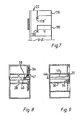
- An endless belt 32 preferably of elastic material couples the two spools by passing around a peripheral groove 34 at one end of the take-up spool 30 (see Figure 9) and around a similar groove in a pulley 36 mounted at the similar end of the take-up spool 28 and connected thereto by a one way clutch as will hereinafter be described.
- the diameter of the pulley 36 is considerably greater than that of the spool 30 and the transmission ratio between the pulley 36 and spool 30 is selected so as to be greater than the transmission ratio between the roll of ribbon on the supply spool to that on the take-up spool, even when the former is full and the latter is empty. Consequently the belt 32 will always attempt to drive the take-up spool 30 at a speed in excess of that required to simply wind on the ribbon (which is being pulled off the supply spool) and in this way the ribbon is tensioned between the two spools.
- the supply spool 28 is provided with a one way clutch to prevent accidental reverse rotation.
- This device is shown in Figure 8 and comprises a coil spring 38 wound tightly around an axle 40 on which the supply spool 28 is fixed.
- the spring includes a tail 42 which engages in an aperture (not visible) formed in the cooperating end face of the pulley 36.
- the pulley 36 is otherwise freely rotatable about the axle 40 relative to the spool 28.
- a knob 44 is mounted on an axial extension 46 of the axle 48 of the take-up spool 30 (see Figures 6 and 9) and manual movement of the ribbon is effected by rotating the knob 44 in an anti-clockwise manner so as to draw ribbon from the spool 28 onto the spool 30.
- the supply spool 28 will also be rotated but at a lower speed than the take-up spool 30 so as to maintain tension.
- the one way clutch connection between spool 28 and pulley 36 prevents spent ribbon from being rewound onto the delivery spool 28.
- knob 44 is accidentally rotated in a clockwise manner, the lost motion connection will cause the slack loop to increase as ribbon is unwound from spool 30 and is not taken up by the delivery spool.
- the intention is that the user will discover that the slack is not being taken up but is in fact increasing before positive drive is effected between the pulley 36 and the spool 28, whereupon it is anticipated that the operator will rotate the knob 44 in the opposite sense (ie anti-clockwise) which will immediately result in the slack being taken up on the take-up spool 30.
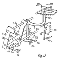
- the envelope path includes a pressure roller 52 mounted between two L-shaped members 54 and 56 forming a sub-assembly (see Figures 2 and 12).
- a shaft 58 extends rigidly between the lower ends of the two members 54 and 56 and a cam follower is situated along the length thereof (see Figure 12).
- the assembly of the members 54 and 56 is pivotal about an axle 62 (see Figure 12) to allow the roller 52 to be raised and lowered relative to the envelope path under the action of a cam 64 mounted on a cam shaft 66.
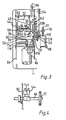
- Shaft 66 is driven by a motor 68 acting through a worm gear 70 and worm wheel 72 (see Figures 3 and 11).
- roller 52 is in the lowered position shown in Figure 2, but upon operation of motor 68 cam 64 is rotated so as to allow the sub-assembly formed by the members 54 and 56 to rotate in an anti-clockwise manner (as shown in Figure 2) under the action of two springs 74 and 76 (see Figure 12). Only one of these springs (spring 74) is visible in Figure 2 and for clarity the springs have been omitted from the underside view in Figure 3. However, referring to Figure 3, the springs in question extend between the holes 78 and 80 in the inturned lower ends of the carriers 54 and 56 and a rigid rod 82 which extends between two side plates 84 and 86 (see Figure 3).
- plate 86 can be seen in Figure 2 due to the fact that plate 84 has been cut away in Figure 2.
- an envelope shown at 88 in Figure 12 is introduced below the cassette housing 16 until its leading edge touches the upper end of a lever 90 which constitutes an envelope sensor.
- the latter is pivoted about an axle 92 and is normally held in a vertical position against a stop (not shown) by a spring 94.
- the lever includes an actuating lug 96 which under the action of the spring 94 is held against the operating member of a microswitch 98 so as to hold the latter in an OPEN condition. This is changed into a CLOSED condition as the upper end of lever 90 is moved in the direction of the arrow 100 in Figure 12.
- the upper end of lever 90 includes a lateral flange 102 which upon intial movement under the influence of the leading edge of the envelope engages the upper end 104 of a Z-shaped member 106 pivoted on the axle 62 and normally held in the position shown in Figure 12 by a spring 106 and a cam 108 also carried by the cam shaft 66. Rotation of the cam shaft 66 will cause cam 108 to move relative to the lower arm of the Z-shaped member 106 and will cause the latter to move against the spring 106 and thereby lower the upper end 104 relative to the flange 102.
- the speed of rotation of the shaft 66 and the position and shape of the cams 64 and 108 are selected so as to ensure that the upper end of the lever 90 inhibits the movement of the envelope in the direction of arrow 100 until the roller 52 has just been raised into its operating position under the action of the springs 74 and 76.
- the roller 52 serves two purposes:
- roller 52 is mounted on shaft 110 which is driven by a second motor 112 via a complex gear train which can best be seen by comparing Figures 2, 3 and 11.
- the output shaft of the motor carries a worm gear 114 which meshes with worm gear 116.
- a smaller diameter toothed wheel 118 linked to the worm wheel 116 by a sleeve 120 (see Figure 3) drives a gear wheel 122 mounted on a shaft 124 which extends through the plate 86.
- a gear wheel 126 which meshes with a gear wheel 128 carried by a sleeve 130 on which a second gear wheel is mounted identified by reference numeral 132 and which provides a driving surface for an endless belt 134 for driving a pinch wheel 136 located at the envelope exit.
- the gear wheel 132 meshes with another similar sized intermediate gear wheel 138 which in turn meshes with another gear wheel of similar size 140 which is attached to the shaft 110 on which the roller 52 is mounted.
- the intermediate gear wheel 138 is in fact mounted on a shaft 142 which extends between the two members 54 and 56 and through a slot (not shown) in the plate 86 so that the intermediate gear wheel 138 moves with the roller 52 and the gear wheel 140.
- gear wheel 132 (not visible in Figure 11 by virtue of being hidden) is mounted by an extension of the shaft 62 on which the sub-assembly formed by members 54 and 56 pivot so that the centre of rotation of gear wheel 138 rotates about the centre of rotation of gear wheel 132 and gear wheel 138 remains in constant mesh both with 132 and 140.
- control signals are derived from the operation of microswitch 98 for controlling the supply of operating current to motor 68.
- Other microswitches are provided as shown in Figure 4 operated by cams on cam shaft 66.
- One of the microswitches designated by reference numeral 144 is set to open when the motor has rotated the cam shaft 66 by an amount just sufficient to raise the roller 52 into its operating position.
- Activation of the thermal points at the print head to commence franking is timed in relation to the controlled entry of the envelope.
- Franking commences when the envelope transport mechanism has taken over to move the envelope through the apparatus.
- the processor delays release of the timed control signals for activating the thermal points by a period of time sufficient to allow the drive motor 68 to raise the pressure roller 52 to engage the envelope and the ribbon.
- the control signals which repeatedly and selectively energise the thermal points must be appropriately timed to incorporate timing variations corresponding to irregularities in envelope transport. It is therefore appropriate to monitor the transport of the envelope through the machine and derive the timing for the thermal point energising signals from the actual movement of the envelope.
- the envelope and ribbon within the cassette travel precisely together and it is therefore possible to monitor the movement of the envelope by monitoring the linear movement of the ribbon.
- the cassette makes provision for monitoring the linear movement of the ribbon within the cassette.
- the ribbon path within the cassette includes a guide roller 148 around which the ribbon passes after it leaves the delivery spool, a second roller 150 just ahead of the print head position and a curved guide surface 152 around which the ribbon passes after leaving the print position and just in advance of the take-up spool.
- the roller 148 is located just behind a window 154 situated at an angled corner of the cassette housing so as to expose the ribbon passing around the roller for engagement by an optical encoder (not shown) carried by the franking machine and located in or extending into the housing into which the cassette is fitted.
- the opposite ends of the cassette are formed with slideways, one of which is denoted by reference numeral the 176.
- Two slideways are provided at the opposite end and can be seen in Figure 7 and denoted by reference numerals 178 and 180.
- the three slideways can be seen in dotted outline in Figure 2.
- protrusions 182, 184 and 186 On the cooperating opposed side walls of the cassette housing are three protrusions 182, 184 and 186 which respectively engage the slideways 176, 178 and 180 and locate the cassette vertically as it is pushed into the housing.
- the slideways include lateral slots 176′, 178′ and 180′ which are divisional to slidingly receive the protrusions 182, 184 and 186 respectively where the cassette has been fully pushed into the housing.
- toggle springs are provided at the rear of the cassette housing which are engaged by the rear of the cassette as the latter is pushed into position.
- One of the toggle springs is shown at 188 in Figure 5 and a similar one (not shown) is located at the opposite end of the cassette housing.
- the toggle spring includes two diverging arms, one designated 190 and a longer one designated 192.
- the rear of the cassette engages the arm 190 and the longer arm 192 engages the underside of the cassette.
- Continued rearward movement of the cassette causes the arm 190 to be moved upwards and rearwards thereby tensioning the spring since the longer arm 192 is prevented from following due to its engagement with the underside of the cassette.
- the cassette can move upwards, and does so, under the action of the two arms 192 of the two springs which at that stage are fully tensioned with the arms 190 almost vertical.
- the movement of the cassette in an upward direction is limited by the depth of the slots 176′, 178′ and 180′ in its ends and once the protrusions have engaged the slots and the cassette has moved into its fully raised position with the protrusions at the bottom of the slots, it remains firmly in that position under the action of the springs.
- Removal of the cassette is achieved quite simply by pressing the cassette in a downward direction within the housing until the protrusions are fully clear of the slots.
- the housing can now move back along the slideways out of the housing under the action of the springs.
- a used ribbon detection lever 198 extends through an opening 200 in the rear wall of the cassette and is pivoted at 202 relative to a microswitch 204.
- the outboard end of the lever 198 rests on the ribbon wrapped around the take-up spool 30 and as the diameter of the latter increases, so the lever 198 is raised.
- the lever will have been raised sufficiently to actuate the microswitch 204, the operation of which is used to indicate via a visible or audible (or both) alarm, that the ribbon cassette is virtually exhausted.
- lever 198 will automatically protrude through the cut away region 200 as the cassette is inserted into the housing and requires no setting-up.
- the machine may be arranged to be switched off after a predetermined amount of use after the microswitch 204 has actuated.
- the exit of the envelope is controlled by the exit pinch wheel 136 and the spring loaded jockey wheel 194 mounted thereabove, and tensioned by a spring 196.
- the pinch wheel is driven by the endless belt 134 as previously described with reference to Figure 3.
Abstract
Description
- This invention relates to a method of and apparatus for printing using a thermal print head.
- Cassettes containing a spool of ribbon in which during use, the ribbon is transferred to another spool, are known. They are employed in tape recoders, typewriters, printers and so on to carry items such as magnetic tape or inked ribbon. These cassettes usually have features, such as sprocketed holes in the centre of one or both of the spools, which allow the apparatus on which the cassette is to be used, to transmit a driving force to the cassette which will wind the used ribbon onto the take-up spool.
- The mechanisms used in such arrangements are complex and a motor or other prime mover is required to power the drive mechanism. This prime mover may be synchronised with the take-up spool speed requirements or, as is more often the case, a slipping clutch is used to automatically control the speed of take-up. In addition, the cassette must he designed so that the drive mechanism will readily engage the cassette. This is usually simplified by allowing the spools to 'float' within the cassette. The spools can then align themselves with the drive mechanism as the cassette is inserted.
- A still more complex arrangement is necessary if the cassette is to be inserted into the apparatus in a direction other than parallel to the axes of rotation of the spools. It may then be necessary to use an arrangement in which the drive mechanism is moved into engagement with the cassette spools after the cassette has been fully inserted.
- According to the invention, there is provided a method of printing using a thermal print head and a ribbon of thermally activatable dye, comprising the steps of producing relative movement between the print head on the one hand and the article to be printed and the ribbon on the other hand, wherein adhesion between the article and the ribbon is created by local heating of the ribbon and is used to effect drive of the ribbon past the print head from a supply spool to a take-up spool.
- The spools may be located in a cassette.
- The invention thus enables a cassette to be used, and obviates the need for an external drive to the take-up spool. Instead the ribbon is pulled from the supply spool and the motion thus generated in the supply spool may be transmitted via a slipping drive arrangement to the takeup spool.
- The thermally activatable dye is carried on the ribbon and after thermal activation, this dye has been found to provide an adhesive force between the ribbon and the printed item which is sufficient to case the ribbon to be unwound from the supply spool when drive is provided only to the printed item. Thus no drive force at all need be provided directly to the ribbon or cassette, only to the item that is being printed.
- An additional advantage of the method of the invention when used with thermal transfer printing apparatus is that it allows lateral movement of the cassette during insertion. Such a feature is used to advantage in two areas: (a) to reduce the chances of the ribbon snagging on the print head and (b) to allow the ribbon inside the cassette to engage with a drive to a sensor for detecting the motion of the ribbon (and therefor the article being printed).
- A method of printing according to the invention, using a cassette for dye impregnated ribbon in a postal franking machine, will now be described with reference to the accompanying drawings, in which:-
- Figure 1 is a perspective view of the franking machine in which the cassette can be used;
- Figure 2 is a front elevation with front plate partly cut away to show an inserted cassette and component parts associated therewith;
- Figure 3 is an underside view of the inside of the machine with certain parts removed for clarity;
- Figure 4 illustrates to an enlarged scale part of the main cam shaft and two microswitches associated therewith;
- Figure 5 is a view of the exit end of the machine with parts removed to reveal internal functional details;
- Figure 6 is a cut away perspective view from one end of a cassette;
- Figure 7 is a view of the opposite end of the cassette;
- Figure 8 is a cross-section through the cassette of Figure 6 showing the non-return mechanism;
- Figure 9 is a similar cross-section through the cassette showing the take-up spool mounting assembly;
- Figure 10 shows the inserted cassette and immediately adjacent cooperating component parts of the machine;
- Figure 11 is a rear view of the lower part of the machine with covers removed, showing the eject wheel drive; and
- Figure 12 is a scrap perspective view showing the envelope stop and release mechanism.
- The improved cassette (shown in Figures 6, 7 and 8) will be described in relation to its use in a postal franking machine (shown in the remaining views of the drawings) although it is to be understood that this application is merely one example of the many applications for the invention.
-
- The franking machine is shown pictorially in Figure 1 and includes a
keyboard 10 for data entry andLED display devices compartment 16 which has adoor 18 which is openable to allow a cassette to be inserted so that the ribbon underlies a thermal printing head located within the machine is located (seeitem 27 in Figure 2) and which extends into thehousing 16 to cooperate with the ribbon housed within the cassette (as will hereinafter be described), in order toprint information on to an envelope or like article which is inserted in the direction of thearrow 20, beneath the cassette compartment. The franked envelope emerges from the other side of the compartment as indicated by thearrow 22. The expression inked ribbon is intended to cover any dye coated or impregnated ribbon or tape, which dye can be deposited onto sheet material in contact therewith. - The printing head forms no part of the present invention but will be described in general so as to provide a more complete understanding of the overall operation of the machine.
- Typically the printer is made up of one or more rows of points which can be individually electrically heated and which are selectively activated in timed relationship to the transport of the envelope relative to the printer. The heated points are commonly referred to as "thermal points". By sandwiching a dye coated or impregnated ribbon between the thermal points and an envelope, so printing onto the envelope can be achieved by selectively activating the thermal points so as to locally heat the ribbon and cause dye to be transferred at the heated point from the ribbon to the envelope surface.
- Where the ribbon is coated or impregnated with thermally activatable dye and the printer is a thermal printer, it has been found that under sufficient pressure, the thermal printing step can produce sufficient adhesion between the ribbon and the envelope, to allow the movement of the latter to effect ribbon feed. This automatically ensures the required synchronism between envelope movement and ribbon movement. The ribbon is automatically peeled away from the envelope surface by causing the paths of the envelope and the ribbon to diverge.
- Referring now to Figures 2 and 5 to 10, the cassette (best seen in Figure 6) comprises an
outer casing 24 shaped to allow it to be fitted into thehousing 16 in the direction of thearrow 26 of Figure 6. After initial horizontal movement into the compartment in thehousing 16, a latch mechanism (to be described later) operates so as to lift the cassette into an elevated position as can best be seen in Figure 2, where the cassette is shown in its operating position within the housing. - The lower section of the
cassette carriage 24 is cut away at 25 to allow the casing to fit over theprinting head 27 with the inkedribbon 29 of the cassette extending below the head. - The
cassette 24 includes adelivery spool 28 and a take-up spool 30. Anendless belt 32 preferably of elastic material couples the two spools by passing around aperipheral groove 34 at one end of the take-up spool 30 (see Figure 9) and around a similar groove in apulley 36 mounted at the similar end of the take-up spool 28 and connected thereto by a one way clutch as will hereinafter be described. The diameter of thepulley 36 is considerably greater than that of thespool 30 and the transmission ratio between thepulley 36 andspool 30 is selected so as to be greater than the transmission ratio between the roll of ribbon on the supply spool to that on the take-up spool, even when the former is full and the latter is empty. Consequently thebelt 32 will always attempt to drive the take-up spool 30 at a speed in excess of that required to simply wind on the ribbon (which is being pulled off the supply spool) and in this way the ribbon is tensioned between the two spools. - Where a non re-usable ribbon is employed, it is important that if the ribbon should become slack for any reason, the slack ribbon cannot be accidently rewound onto the
supply spool 28. To this end thesupply spool 28 is provided with a one way clutch to prevent accidental reverse rotation. This device is shown in Figure 8 and comprises acoil spring 38 wound tightly around anaxle 40 on which thesupply spool 28 is fixed. The spring includes a tail 42 which engages in an aperture (not visible) formed in the cooperating end face of thepulley 36. Thepulley 36 is otherwise freely rotatable about theaxle 40 relative to thespool 28. Drive between thepulley 36 and thespool 28 is transmitted via the spring and tail when the pulley is rotated in one direction but the tightness of the spring on the axle is such that slipping will occur when the pulley is rotated in the opposite sense. It has been found that the same arrangement can also be used in which the spring slips relative to the axle in both directions of rotation, but to a much smaller extent in the winding direction than is the opposite direction. - Under normal circumstances ribbon drive is effected as previously mentioned by frictional contact and adhesion between the ribbon and the article to be printed. However, a
knob 44 is mounted on an axial extension 46 of theaxle 48 of the take-up spool 30 (see Figures 6 and 9) and manual movement of the ribbon is effected by rotating theknob 44 in an anti-clockwise manner so as to draw ribbon from thespool 28 onto thespool 30. - Due to the presence of the
belt 32, thesupply spool 28 will also be rotated but at a lower speed than the take-upspool 30 so as to maintain tension. - If the
ribbon web 29 becomes slack, the one way clutch connection betweenspool 28 andpulley 36 prevents spent ribbon from being rewound onto thedelivery spool 28. Thus ifknob 44 is accidentally rotated in a clockwise manner, the lost motion connection will cause the slack loop to increase as ribbon is unwound fromspool 30 and is not taken up by the delivery spool. The intention is that the user will discover that the slack is not being taken up but is in fact increasing before positive drive is effected between thepulley 36 and thespool 28, whereupon it is anticipated that the operator will rotate theknob 44 in the opposite sense (ie anti-clockwise) which will immediately result in the slack being taken up on the take-upspool 30. - A fuller understanding of the operation of the cassette will be obtained by considering how it cooperates with the passage of an envelope through the franking machine shown in Figures 1 and 2.
- The envelope path includes a
pressure roller 52 mounted between two L-shapedmembers 54 and 56 forming a sub-assembly (see Figures 2 and 12). Ashaft 58 extends rigidly between the lower ends of the twomembers 54 and 56 and a cam follower is situated along the length thereof (see Figure 12). The assembly of themembers 54 and 56 is pivotal about an axle 62 (see Figure 12) to allow theroller 52 to be raised and lowered relative to the envelope path under the action of acam 64 mounted on acam shaft 66. -
Shaft 66 is driven by amotor 68 acting through aworm gear 70 and worm wheel 72 (see Figures 3 and 11). - Initially the
roller 52 is in the lowered position shown in Figure 2, but upon operation ofmotor 68cam 64 is rotated so as to allow the sub-assembly formed by themembers 54 and 56 to rotate in an anti-clockwise manner (as shown in Figure 2) under the action of twosprings 74 and 76 (see Figure 12). Only one of these springs (spring 74) is visible in Figure 2 and for clarity the springs have been omitted from the underside view in Figure 3. However, referring to Figure 3, the springs in question extend between theholes carriers 54 and 56 and arigid rod 82 which extends between twoside plates 84 and 86 (see Figure 3). - To assist in reconciling the Figures,
plate 86 can be seen in Figure 2 due to the fact thatplate 84 has been cut away in Figure 2. - In operation, an envelope shown at 88 in Figure 12 is introduced below the
cassette housing 16 until its leading edge touches the upper end of alever 90 which constitutes an envelope sensor. The latter is pivoted about anaxle 92 and is normally held in a vertical position against a stop (not shown) by aspring 94. The lever includes anactuating lug 96 which under the action of thespring 94 is held against the operating member of amicroswitch 98 so as to hold the latter in an OPEN condition. This is changed into a CLOSED condition as the upper end oflever 90 is moved in the direction of thearrow 100 in Figure 12. - The upper end of
lever 90 includes alateral flange 102 which upon intial movement under the influence of the leading edge of the envelope engages theupper end 104 of a Z-shapedmember 106 pivoted on theaxle 62 and normally held in the position shown in Figure 12 by aspring 106 and acam 108 also carried by thecam shaft 66. Rotation of thecam shaft 66 will causecam 108 to move relative to the lower arm of the Z-shapedmember 106 and will cause the latter to move against thespring 106 and thereby lower theupper end 104 relative to theflange 102. Untilend 104 drops below the lower edge of theflange 102, the envelope is prevented from passing further through the machine but as soon as the upper end oflever 104 drops below theflange 102 , thelever 90 can continue to move in the direction ofarrow 100, pivoting about theaxle 92 against the action ofreturn spring 94, and permitting onward movement of the envelope in the direction ofarrow 100. - The speed of rotation of the
shaft 66 and the position and shape of thecams lever 90 inhibits the movement of the envelope in the direction ofarrow 100 until theroller 52 has just been raised into its operating position under the action of thesprings - The
roller 52 serves two purposes: - a) to provide a firm but resilient pad as a backing for the envelope or other item during printing and
- b) to provide the necessary drive for moving the envelope or other article through the franking machine at least during the printing operation.
- To this end the
roller 52 is mounted onshaft 110 which is driven by asecond motor 112 via a complex gear train which can best be seen by comparing Figures 2, 3 and 11. - The output shaft of the motor carries a
worm gear 114 which meshes withworm gear 116. A smaller diametertoothed wheel 118 linked to theworm wheel 116 by a sleeve 120 (see Figure 3) drives agear wheel 122 mounted on ashaft 124 which extends through theplate 86. Beyond the plate and not visible in Figure 2, is mounted anothergear wheel 126 which meshes with agear wheel 128 carried by asleeve 130 on which a second gear wheel is mounted identified byreference numeral 132 and which provides a driving surface for anendless belt 134 for driving apinch wheel 136 located at the envelope exit. - The
gear wheel 132 meshes with another similar sizedintermediate gear wheel 138 which in turn meshes with another gear wheel ofsimilar size 140 which is attached to theshaft 110 on which theroller 52 is mounted. - Although not clearly shown in Figures 3 and 11, the
intermediate gear wheel 138 is in fact mounted on ashaft 142 which extends between the twomembers 54 and 56 and through a slot (not shown) in theplate 86 so that theintermediate gear wheel 138 moves with theroller 52 and thegear wheel 140. - Likewise the gear wheel 132 (not visible in Figure 11 by virtue of being hidden) is mounted by an extension of the
shaft 62 on which the sub-assembly formed bymembers 54 and 56 pivot so that the centre of rotation ofgear wheel 138 rotates about the centre of rotation ofgear wheel 132 andgear wheel 138 remains in constant mesh both with 132 and 140. - Although no detail is given of the control circuitry, reference has already been made to the fact that control signals are derived from the operation of
microswitch 98 for controlling the supply of operating current tomotor 68. Other microswitches are provided as shown in Figure 4 operated by cams oncam shaft 66. One of the microswitches designated byreference numeral 144 is set to open when the motor has rotated thecam shaft 66 by an amount just sufficient to raise theroller 52 into its operating position. - Activation of the thermal points at the print head to commence franking is timed in relation to the controlled entry of the envelope. Franking commences when the envelope transport mechanism has taken over to move the envelope through the apparatus. In order to initiate the print control signals at the correct instant, the processor delays release of the timed control signals for activating the thermal points by a period of time sufficient to allow the
drive motor 68 to raise thepressure roller 52 to engage the envelope and the ribbon. - Due to the differing shapes, thicknesses and surfaces of envelopes and other postal items which may be entered into the machine, and additionally due to variations along the length of any given item, a precisely uniform movement of the envelope by its transport mechanism cannot be ensured. Consequently in order to arrange that the franking information is imparted without distortion, the control signals which repeatedly and selectively energise the thermal points must be appropriately timed to incorporate timing variations corresponding to irregularities in envelope transport. It is therefore appropriate to monitor the transport of the envelope through the machine and derive the timing for the thermal point energising signals from the actual movement of the envelope.
- In the machine under consideration, the envelope and ribbon within the cassette travel precisely together and it is therefore possible to monitor the movement of the envelope by monitoring the linear movement of the ribbon.
- To this end the cassette makes provision for monitoring the linear movement of the ribbon within the cassette. Referring to Figures 6 and 10, it will be seen that the ribbon path within the cassette includes a
guide roller 148 around which the ribbon passes after it leaves the delivery spool, asecond roller 150 just ahead of the print head position and acurved guide surface 152 around which the ribbon passes after leaving the print position and just in advance of the take-up spool. Theroller 148 is located just behind awindow 154 situated at an angled corner of the cassette housing so as to expose the ribbon passing around the roller for engagement by an optical encoder (not shown) carried by the franking machine and located in or extending into the housing into which the cassette is fitted. - Mention has previously been made of a two-stage operation for inserting the cassette into the housing. This is occassioned by virtue of the fact that the cassette has to be inserted into the housing broadside-on in the direction of
arrow 26 in Figure 6 but after it has been fully located at the rear of the housing, it must then be lifted so as to bring thewindow 154 just below thewheel 156 of the encoder. The cassette is shown in its raised and operating position in Figure 2 with theroller 148 in contact (through the ribbon) with thewheel 156. - To achieve the horizontal and vertical motion, the opposite ends of the cassette are formed with slideways, one of which is denoted by reference numeral the 176. Two slideways are provided at the opposite end and can be seen in Figure 7 and denoted by
reference numerals - On the cooperating opposed side walls of the cassette housing are three
protrusions slideways - The slideways include
lateral slots 176′, 178′ and 180′ which are divisional to slidingly receive theprotrusions - In order to facilitate the insertion of the cassette into its final electrical position in which the protrusions engage in the slots as opposed to the slidways, toggle springs are provided at the rear of the cassette housing which are engaged by the rear of the cassette as the latter is pushed into position. One of the toggle springs is shown at 188 in Figure 5 and a similar one (not shown) is located at the opposite end of the cassette housing. The toggle spring includes two diverging arms, one designated 190 and a longer one designated 192. On initial insertion the rear of the cassette engages the
arm 190 and thelonger arm 192 engages the underside of the cassette. Continued rearward movement of the cassette causes thearm 190 to be moved upwards and rearwards thereby tensioning the spring since thelonger arm 192 is prevented from following due to its engagement with the underside of the cassette. - As soon as the cassette has been pushed into the housing to an extent sufficient to enable the protrusions to engage the vertical slots in its ends, the cassette can move upwards, and does so, under the action of the two
arms 192 of the two springs which at that stage are fully tensioned with thearms 190 almost vertical. - The movement of the cassette in an upward direction is limited by the depth of the
slots 176′, 178′ and 180′ in its ends and once the protrusions have engaged the slots and the cassette has moved into its fully raised position with the protrusions at the bottom of the slots, it remains firmly in that position under the action of the springs. - Removal of the cassette is achieved quite simply by pressing the cassette in a downward direction within the housing until the protrusions are fully clear of the slots. The housing can now move back along the slideways out of the housing under the action of the springs.
- Since the ribbon will normally be hidden from view, it may be important to determine when the ribbon has been nearly used up. To this end a used
ribbon detection lever 198 extends through anopening 200 in the rear wall of the cassette and is pivoted at 202 relative to amicroswitch 204. The outboard end of thelever 198 rests on the ribbon wrapped around the take-upspool 30 and as the diameter of the latter increases, so thelever 198 is raised. At a given point the lever will have been raised sufficiently to actuate themicroswitch 204, the operation of which is used to indicate via a visible or audible (or both) alarm, that the ribbon cassette is virtually exhausted. - It will be seen that the
lever 198 will automatically protrude through the cut awayregion 200 as the cassette is inserted into the housing and requires no setting-up. - The machine may be arranged to be switched off after a predetermined amount of use after the
microswitch 204 has actuated. - The exit of the envelope is controlled by the
exit pinch wheel 136 and the spring loadedjockey wheel 194 mounted thereabove, and tensioned by aspring 196. The pinch wheel is driven by theendless belt 134 as previously described with reference to Figure 3. - Reference is made to copending European Patent Applications Nos. 86300215.0 and 86300214.3 which are directed to subject matter related to that described herein.
Claims (9)
Priority Applications (2)
| Application Number | Priority Date | Filing Date | Title |
|---|---|---|---|
| EP89109542A EP0337501B1 (en) | 1985-01-19 | 1986-01-15 | Thermal printing |
| AT89109542T ATE73052T1 (en) | 1985-01-19 | 1986-01-15 | THERMAL PRINT. |
Applications Claiming Priority (3)
| Application Number | Priority Date | Filing Date | Title |
|---|---|---|---|
| GB08501404A GB2169875B (en) | 1985-01-19 | 1985-01-19 | Improvements in ribbon cassettes |
| GB8501404 | 1985-01-19 | ||
| EP89109542A EP0337501B1 (en) | 1985-01-19 | 1986-01-15 | Thermal printing |
Related Parent Applications (1)
| Application Number | Title | Priority Date | Filing Date |
|---|---|---|---|
| EP86300215.0 Division | 1986-01-15 |
Publications (3)
| Publication Number | Publication Date |
|---|---|
| EP0337501A2 true EP0337501A2 (en) | 1989-10-18 |
| EP0337501A3 EP0337501A3 (en) | 1989-10-25 |
| EP0337501B1 EP0337501B1 (en) | 1992-03-04 |
Family
ID=10573124
Family Applications (2)
| Application Number | Title | Priority Date | Filing Date |
|---|---|---|---|
| EP86300215A Expired - Lifetime EP0189984B1 (en) | 1985-01-19 | 1986-01-15 | Improvements in ribbon cassettes |
| EP89109542A Expired - Lifetime EP0337501B1 (en) | 1985-01-19 | 1986-01-15 | Thermal printing |
Family Applications Before (1)
| Application Number | Title | Priority Date | Filing Date |
|---|---|---|---|
| EP86300215A Expired - Lifetime EP0189984B1 (en) | 1985-01-19 | 1986-01-15 | Improvements in ribbon cassettes |
Country Status (13)
| Country | Link |
|---|---|
| US (2) | US4767228A (en) |
| EP (2) | EP0189984B1 (en) |
| JP (1) | JPS61181673A (en) |
| KR (1) | KR930011869B1 (en) |
| AR (1) | AR242742A1 (en) |
| AT (2) | ATE50202T1 (en) |
| AU (1) | AU580651B2 (en) |
| BR (1) | BR8600196A (en) |
| CA (1) | CA1288717C (en) |
| DE (2) | DE3684157D1 (en) |
| GB (2) | GB2169875B (en) |
| SG (1) | SG14689G (en) |
| ZA (1) | ZA86246B (en) |
Families Citing this family (29)
| Publication number | Priority date | Publication date | Assignee | Title |
|---|---|---|---|---|
| JPH0212857U (en) * | 1988-07-11 | 1990-01-26 | ||
| DE69026316T2 (en) * | 1989-07-20 | 1996-09-19 | Canon Kk | Recording device and method using thermal transfer |
| JPH03130179A (en) * | 1989-07-20 | 1991-06-03 | Canon Inc | Thermal transfer recording device and thermal transfer recording |
| JP2550191B2 (en) * | 1989-12-25 | 1996-11-06 | 株式会社日立製作所 | Thermal transfer film cassette and ink film used therefor |
| JPH0471877A (en) * | 1990-07-13 | 1992-03-06 | Tokyo Electric Co Ltd | Transfer type printer |
| JPH0473175A (en) * | 1990-07-13 | 1992-03-09 | Tokyo Electric Co Ltd | Printer |
| JP3047202B2 (en) * | 1992-04-27 | 2000-05-29 | 株式会社サトー | Prevention mechanism of carbon ribbon slack of printing device |
| FR2692838B1 (en) * | 1992-06-24 | 1994-09-02 | Axiohm | Device for recording the operations of a thermal transfer printer. |
| FR2704181B1 (en) * | 1993-04-21 | 1996-01-12 | Axiohm | DEVICE FOR RECORDING THE OPERATIONS OF A TRANSFER THERMAL PRINTER. |
| EP0586265A1 (en) * | 1992-06-24 | 1994-03-09 | Axiohm | Operation Register Device for thermal transfer printers |
| US5339280A (en) * | 1992-09-24 | 1994-08-16 | Pitney Bowes Inc. | Platen roller and pressure roller assemblies for thermal postage meter |
| US5318368A (en) * | 1992-09-24 | 1994-06-07 | Pitney Bowes Inc. | Thermal transfer ribbon having ribbon follower |
| US5468080A (en) * | 1993-03-25 | 1995-11-21 | Jones; William B. | Poly bag printer for packaging machine |
| US5524995A (en) * | 1994-11-14 | 1996-06-11 | Pitney Bowes, Inc. | Apparatus and method for detecting the position of envelopes in a mailing machine |
| GB2302523B (en) * | 1995-04-12 | 1998-03-25 | Prestek Ltd | Method of printing |
| KR100394394B1 (en) * | 1996-03-12 | 2003-10-11 | 세이코 엡슨 가부시키가이샤 | printer |
| US5959652A (en) * | 1997-07-11 | 1999-09-28 | Pitney Bowes Inc. | Thermal ink ribbon cassette for mailing machines |
| EP1607912B1 (en) * | 2001-10-02 | 2013-03-20 | Francotyp-Postalia GmbH | Method and device for opening a security housing |
| DE10164527A1 (en) * | 2001-12-15 | 2003-07-10 | Francotyp Postalia Ag | Arrangement for protecting a print module in a mail processing device |
| DE10164526A1 (en) | 2001-12-15 | 2003-06-18 | Francotyp Postalia Ag | security chassis |
| US6848845B2 (en) | 2002-05-08 | 2005-02-01 | Zih Corp. | Thermal ribbon cartridge or roll with slack ribbon retraction |
| US20050084310A1 (en) * | 2003-10-16 | 2005-04-21 | Alps Electric Co., Ltd. | Ribbon cassette for thermal transfer printer |
| DE202004010858U1 (en) * | 2004-07-06 | 2004-11-04 | Francotyp-Postalia Ag & Co. Kg | Arrangement of a communication unit in a device |
| DE202004011390U1 (en) | 2004-07-16 | 2004-10-28 | Francotyp-Postalia Ag & Co. Kg | Arrangement for a manually operated humidifier |
| DE202004015279U1 (en) * | 2004-10-01 | 2005-01-13 | Francotyp-Postalia Ag & Co. Kg | Arrangement for a printing mail processing device |
| DE202004016611U1 (en) | 2004-10-27 | 2005-02-10 | Francotyp-Postalia Ag & Co. Kg | Safety housing with ventilation openings |
| JP6270430B2 (en) * | 2013-11-22 | 2018-01-31 | キヤノン株式会社 | Ink ribbon cassette and printing apparatus |
| JP1640670S (en) * | 2018-10-18 | 2019-09-09 | Foil transfer device | |
| CN114683706B (en) * | 2022-03-07 | 2023-04-11 | 深圳市奥莱新创科技有限公司 | Temporary license plate printer |
Citations (4)
| Publication number | Priority date | Publication date | Assignee | Title |
|---|---|---|---|---|
| US3090299A (en) * | 1961-06-02 | 1963-05-21 | Potter Instrument Co Inc | Ribbon tensioning mechanism for high speed printers |
| US3939957A (en) * | 1973-12-11 | 1976-02-24 | General Electric Company | Carriage operated ribbon drive and reverse mechanism |
| EP0009595A1 (en) * | 1978-09-28 | 1980-04-16 | International Business Machines Corporation | Electrothermal printing apparatus |
| EP0054664A2 (en) * | 1980-12-19 | 1982-06-30 | International Business Machines Corporation | Ribbon feed system for a matrix printer |
Family Cites Families (19)
| Publication number | Priority date | Publication date | Assignee | Title |
|---|---|---|---|---|
| DE1176392B (en) * | 1963-02-15 | 1964-08-20 | Telefunken Patent | Winding plate drive for magnetic tape devices |
| US3455431A (en) * | 1968-03-07 | 1969-07-15 | Trustees Employees Savings | Method and apparatus for simultaneously moving a marking tape and other tape |
| US3759433A (en) * | 1970-11-10 | 1973-09-18 | Gerber Scientific Instr Co | Method and apparatus for transporting a strip of recording material |
| US3762530A (en) * | 1971-08-06 | 1973-10-02 | Ncr Co | Printing ribbon indexing system |
| US3967790A (en) * | 1974-03-07 | 1976-07-06 | Qume Corporation | Cartridge drive apparatus |
| DE2700812A1 (en) * | 1977-01-11 | 1978-07-13 | Hartmann & Braun Ag | Recording machine winding roller slipping clutch - comprises pairs of friction washers with driving lugs aligned in axial grooves |
| US4151039A (en) * | 1978-05-30 | 1979-04-24 | Lash Donald W | Double adhesive tape dispenser |
| FR2464146A1 (en) * | 1979-09-03 | 1981-03-06 | Sodern | Transport and simultaneous marking of documents - uses inked ribbon to help transport document past print head |
| US4544291A (en) * | 1980-03-13 | 1985-10-01 | Nippon Electric Co., Ltd. | Invertible inked ribbon cartridge having two sets of feed mechanisms for an impact-serial printer |
| JPS57201686A (en) * | 1981-06-05 | 1982-12-10 | Sony Corp | Color printer |
| US4467976A (en) * | 1982-10-04 | 1984-08-28 | International Business Machines Corporation | Ribbon cartridge comprising a stuffer box intermediate a supply reel and take-up reel |
| JPS59145161A (en) * | 1983-02-08 | 1984-08-20 | Hitachi Ltd | Thermal transfer printer |
| JPS59204584A (en) * | 1983-05-07 | 1984-11-19 | Mitsubishi Electric Corp | Thermal transfer printer |
| JPS59217548A (en) * | 1983-05-23 | 1984-12-07 | Hitachi Ltd | Thermal transfer recorder |
| US4591879A (en) * | 1984-01-28 | 1986-05-27 | Kabushiki Kaisha Sato | Winding mechanism for tape-like web |
| US4568950A (en) * | 1984-06-19 | 1986-02-04 | Pitney Bowes Inc. | Postage meter-thermal tape pressure and drive control printer |
| GB2169853B (en) * | 1985-01-19 | 1988-11-02 | Francotyp Postalia Gmbh | Improvements in movement monitoring devices |
| US4739343A (en) * | 1986-05-09 | 1988-04-19 | Pitney Bowes Inc. | Thermal printing system for postage meter mailing machine application |
| JP3706680B2 (en) * | 1996-06-18 | 2005-10-12 | 本田技研工業株式会社 | Liquid-filled bush |
-
1985
- 1985-01-19 GB GB08501404A patent/GB2169875B/en not_active Expired
-
1986
- 1986-01-13 ZA ZA86246A patent/ZA86246B/en unknown
- 1986-01-14 US US06/818,656 patent/US4767228A/en not_active Expired - Lifetime
- 1986-01-15 AT AT86300215T patent/ATE50202T1/en not_active IP Right Cessation
- 1986-01-15 AT AT89109542T patent/ATE73052T1/en not_active IP Right Cessation
- 1986-01-15 EP EP86300215A patent/EP0189984B1/en not_active Expired - Lifetime
- 1986-01-15 DE DE8989109542T patent/DE3684157D1/en not_active Expired - Lifetime
- 1986-01-15 EP EP89109542A patent/EP0337501B1/en not_active Expired - Lifetime
- 1986-01-15 DE DE8686300215T patent/DE3668836D1/en not_active Expired - Fee Related
- 1986-01-17 JP JP61008804A patent/JPS61181673A/en active Pending
- 1986-01-17 AR AR86302882A patent/AR242742A1/en active
- 1986-01-17 BR BR8600196A patent/BR8600196A/en unknown
- 1986-01-17 AU AU52522/86A patent/AU580651B2/en not_active Ceased
- 1986-01-17 CA CA000499786A patent/CA1288717C/en not_active Expired - Lifetime
- 1986-01-18 KR KR1019860000298A patent/KR930011869B1/en not_active IP Right Cessation
-
1987
- 1987-06-16 GB GB08714004A patent/GB2192155B/en not_active Expired
-
1988
- 1988-07-20 US US07/221,659 patent/US4886384A/en not_active Expired - Lifetime
-
1989
- 1989-03-07 SG SG146/89A patent/SG14689G/en unknown
Patent Citations (4)
| Publication number | Priority date | Publication date | Assignee | Title |
|---|---|---|---|---|
| US3090299A (en) * | 1961-06-02 | 1963-05-21 | Potter Instrument Co Inc | Ribbon tensioning mechanism for high speed printers |
| US3939957A (en) * | 1973-12-11 | 1976-02-24 | General Electric Company | Carriage operated ribbon drive and reverse mechanism |
| EP0009595A1 (en) * | 1978-09-28 | 1980-04-16 | International Business Machines Corporation | Electrothermal printing apparatus |
| EP0054664A2 (en) * | 1980-12-19 | 1982-06-30 | International Business Machines Corporation | Ribbon feed system for a matrix printer |
Also Published As
| Publication number | Publication date |
|---|---|
| GB2169875A (en) | 1986-07-23 |
| EP0189984B1 (en) | 1990-02-07 |
| BR8600196A (en) | 1986-09-30 |
| JPS61181673A (en) | 1986-08-14 |
| AR242742A1 (en) | 1993-05-31 |
| EP0337501A3 (en) | 1989-10-25 |
| GB8714004D0 (en) | 1987-07-22 |
| EP0189984A2 (en) | 1986-08-06 |
| GB2192155B (en) | 1988-10-05 |
| GB2192155A (en) | 1988-01-06 |
| EP0189984A3 (en) | 1987-04-29 |
| CA1288717C (en) | 1991-09-10 |
| GB2169875B (en) | 1988-09-14 |
| KR930011869B1 (en) | 1993-12-21 |
| ATE73052T1 (en) | 1992-03-15 |
| ZA86246B (en) | 1986-08-27 |
| DE3684157D1 (en) | 1992-04-09 |
| SG14689G (en) | 1989-06-09 |
| US4767228A (en) | 1988-08-30 |
| KR860005707A (en) | 1986-08-11 |
| AU5252286A (en) | 1986-07-24 |
| EP0337501B1 (en) | 1992-03-04 |
| GB8501404D0 (en) | 1985-02-20 |
| AU580651B2 (en) | 1989-01-27 |
| DE3668836D1 (en) | 1990-03-15 |
| US4886384A (en) | 1989-12-12 |
| ATE50202T1 (en) | 1990-02-15 |
Similar Documents
| Publication | Publication Date | Title |
|---|---|---|
| EP0337501B1 (en) | Thermal printing | |
| EP0189269B1 (en) | Improvements in movement monitoring devices | |
| US5435657A (en) | Label printer and tape and ink ribbon cartridge for use therein | |
| US4454517A (en) | Printing apparatus with coacting printer head movement and paper advancement | |
| EP0180370B1 (en) | A printer including paper feed and eject control apparatus | |
| US4999016A (en) | Hand recording apparatus | |
| US5431504A (en) | Printing apparatus with cassette | |
| US4930913A (en) | Thermal printing device and tape supply cartridge therefor | |
| JPH0768814A (en) | Tape printing device | |
| US5959652A (en) | Thermal ink ribbon cassette for mailing machines | |
| EP0589722B1 (en) | Thermal printing postage meter | |
| EP0189268B1 (en) | Apparatus for receiving cassettes | |
| KR870000996B1 (en) | Automatic winder for label | |
| JPS5820633A (en) | Cassette type labeller | |
| JPS6331979Y2 (en) | ||
| JPS61132368A (en) | Cassette-fitting device | |
| JPS61132367A (en) | Ribbon cassette | |
| JPH04275173A (en) | Apparatus for prescribing position of tape in tape cartridge | |
| JPS61272183A (en) | Thermal transfer printer | |
| JPH0126350B2 (en) | ||
| JPH04299170A (en) | Ribbon cassette for thermal printer | |
| JPS62270375A (en) | Ink ribbon apparatus | |
| JPS61272184A (en) | Thermal transfer printer | |
| JPH01209172A (en) | Tape-containing cassette for thermal transfer type printer |
Legal Events
| Date | Code | Title | Description |
|---|---|---|---|
| PUAI | Public reference made under article 153(3) epc to a published international application that has entered the european phase |
Free format text: ORIGINAL CODE: 0009012 |
|
| PUAL | Search report despatched |
Free format text: ORIGINAL CODE: 0009013 |
|
| AC | Divisional application: reference to earlier application |
Ref document number: 189984 Country of ref document: EP |
|
| AK | Designated contracting states |
Kind code of ref document: A2 Designated state(s): AT BE CH DE FR GB IT LI LU NL SE |
|
| AK | Designated contracting states |
Kind code of ref document: A3 Designated state(s): AT BE CH DE FR GB IT LI LU NL SE |
|
| 17P | Request for examination filed |
Effective date: 19891030 |
|
| 17Q | First examination report despatched |
Effective date: 19910513 |
|
| ITF | It: translation for a ep patent filed |
Owner name: STUDIO INGG. FISCHETTI & WEBER |
|
| GRAA | (expected) grant |
Free format text: ORIGINAL CODE: 0009210 |
|
| AC | Divisional application: reference to earlier application |
Ref document number: 189984 Country of ref document: EP |
|
| AK | Designated contracting states |
Kind code of ref document: B1 Designated state(s): AT BE CH DE FR GB IT LI LU NL SE |
|
| PG25 | Lapsed in a contracting state [announced via postgrant information from national office to epo] |
Ref country code: BE Effective date: 19920304 Ref country code: AT Effective date: 19920304 |
|
| REF | Corresponds to: |
Ref document number: 73052 Country of ref document: AT Date of ref document: 19920315 Kind code of ref document: T |
|
| REF | Corresponds to: |
Ref document number: 3684157 Country of ref document: DE Date of ref document: 19920409 |
|
| ET | Fr: translation filed | ||
| PLBE | No opposition filed within time limit |
Free format text: ORIGINAL CODE: 0009261 |
|
| STAA | Information on the status of an ep patent application or granted ep patent |
Free format text: STATUS: NO OPPOSITION FILED WITHIN TIME LIMIT |
|
| PG25 | Lapsed in a contracting state [announced via postgrant information from national office to epo] |
Ref country code: LU Free format text: LAPSE BECAUSE OF NON-PAYMENT OF DUE FEES Effective date: 19930131 |
|
| 26N | No opposition filed | ||
| PG25 | Lapsed in a contracting state [announced via postgrant information from national office to epo] |
Ref country code: NL Effective date: 19930801 |
|
| NLV4 | Nl: lapsed or anulled due to non-payment of the annual fee | ||
| EAL | Se: european patent in force in sweden |
Ref document number: 89109542.4 |
|
| REG | Reference to a national code |
Ref country code: GB Ref legal event code: IF02 |
|
| PGFP | Annual fee paid to national office [announced via postgrant information from national office to epo] |
Ref country code: DE Payment date: 20041109 Year of fee payment: 20 |
|
| PGFP | Annual fee paid to national office [announced via postgrant information from national office to epo] |
Ref country code: GB Payment date: 20041112 Year of fee payment: 20 |
|
| PGFP | Annual fee paid to national office [announced via postgrant information from national office to epo] |
Ref country code: FR Payment date: 20041130 Year of fee payment: 20 |
|
| PGFP | Annual fee paid to national office [announced via postgrant information from national office to epo] |
Ref country code: SE Payment date: 20050118 Year of fee payment: 20 |
|
| REG | Reference to a national code |
Ref country code: GB Ref legal event code: PE20 |
|
| PGFP | Annual fee paid to national office [announced via postgrant information from national office to epo] |
Ref country code: CH Payment date: 20050426 Year of fee payment: 20 |
|
| PGFP | Annual fee paid to national office [announced via postgrant information from national office to epo] |
Ref country code: IT Payment date: 20050725 Year of fee payment: 20 |
|
| PG25 | Lapsed in a contracting state [announced via postgrant information from national office to epo] |
Ref country code: GB Free format text: LAPSE BECAUSE OF EXPIRATION OF PROTECTION Effective date: 20060114 |
|
| REG | Reference to a national code |
Ref country code: CH Ref legal event code: PL |
|
| EUG | Se: european patent has lapsed |