EP0336985B1 - Method for manufacturing an optical probe - Google Patents
Method for manufacturing an optical probe Download PDFInfo
- Publication number
- EP0336985B1 EP0336985B1 EP88105676A EP88105676A EP0336985B1 EP 0336985 B1 EP0336985 B1 EP 0336985B1 EP 88105676 A EP88105676 A EP 88105676A EP 88105676 A EP88105676 A EP 88105676A EP 0336985 B1 EP0336985 B1 EP 0336985B1
- Authority
- EP
- European Patent Office
- Prior art keywords
- sensor
- glue
- sheath
- sensors
- blood
- Prior art date
- Legal status (The legal status is an assumption and is not a legal conclusion. Google has not performed a legal analysis and makes no representation as to the accuracy of the status listed.)
- Expired - Lifetime
Links
Images


Classifications
-
- G—PHYSICS
- G01—MEASURING; TESTING
- G01N—INVESTIGATING OR ANALYSING MATERIALS BY DETERMINING THEIR CHEMICAL OR PHYSICAL PROPERTIES
- G01N33/00—Investigating or analysing materials by specific methods not covered by groups G01N1/00 - G01N31/00
-
- A—HUMAN NECESSITIES
- A61—MEDICAL OR VETERINARY SCIENCE; HYGIENE
- A61B—DIAGNOSIS; SURGERY; IDENTIFICATION
- A61B5/00—Measuring for diagnostic purposes; Identification of persons
- A61B5/145—Measuring characteristics of blood in vivo, e.g. gas concentration, pH value; Measuring characteristics of body fluids or tissues, e.g. interstitial fluid, cerebral tissue
- A61B5/14539—Measuring characteristics of blood in vivo, e.g. gas concentration, pH value; Measuring characteristics of body fluids or tissues, e.g. interstitial fluid, cerebral tissue for measuring pH
-
- A—HUMAN NECESSITIES
- A61—MEDICAL OR VETERINARY SCIENCE; HYGIENE
- A61B—DIAGNOSIS; SURGERY; IDENTIFICATION
- A61B5/00—Measuring for diagnostic purposes; Identification of persons
- A61B5/145—Measuring characteristics of blood in vivo, e.g. gas concentration, pH value; Measuring characteristics of body fluids or tissues, e.g. interstitial fluid, cerebral tissue
- A61B5/1455—Measuring characteristics of blood in vivo, e.g. gas concentration, pH value; Measuring characteristics of body fluids or tissues, e.g. interstitial fluid, cerebral tissue using optical sensors, e.g. spectral photometrical oximeters
- A61B5/1459—Measuring characteristics of blood in vivo, e.g. gas concentration, pH value; Measuring characteristics of body fluids or tissues, e.g. interstitial fluid, cerebral tissue using optical sensors, e.g. spectral photometrical oximeters invasive, e.g. introduced into the body by a catheter
-
- G—PHYSICS
- G01—MEASURING; TESTING
- G01N—INVESTIGATING OR ANALYSING MATERIALS BY DETERMINING THEIR CHEMICAL OR PHYSICAL PROPERTIES
- G01N21/00—Investigating or analysing materials by the use of optical means, i.e. using sub-millimetre waves, infrared, visible or ultraviolet light
- G01N21/75—Systems in which material is subjected to a chemical reaction, the progress or the result of the reaction being investigated
- G01N21/77—Systems in which material is subjected to a chemical reaction, the progress or the result of the reaction being investigated by observing the effect on a chemical indicator
- G01N21/7703—Systems in which material is subjected to a chemical reaction, the progress or the result of the reaction being investigated by observing the effect on a chemical indicator using reagent-clad optical fibres or optical waveguides
Definitions
- This invention relates to a method for manufacturing an optical probe for the invasive measurement of blood parameters, said optical probe comprising at least one sensor sensitive to a blood gas parameter such as pO2 or pCO2 and at least one additional sensor sensitive to the pH value of the blood, said sensors having selective membranes, and said optical probe further comprising a sheath at least partially covering said sensors and fastened on said sensor by a glue.
- a blood gas parameter such as pO2 or pCO2
- Probes for the invasive measurement of blood parameters consist of at least one sensor comprising an optical fiber, said fiber ending up with a gel zone containing a dye.
- the optical density or another optical parameter of said dye varies with the blood parameter (such as pH) to be measured.
- a reflector is positioned on the other side of the dye-containing gel.
- the end of the fiber, the gel and the reflector are surrounded by a semi-permeable envelope (for example, a hydrogen ion permeable envelope in the case of a pH sensor) to keep the gel in place.
- Light from this optical fiber passes the dye-containing gel, is reflected by said reflector, passes the gel again and is transmitted through the optical fiber to an appropriate detector which measures light attenuation or changes in other optical parameters caused by the dye.
- This attenuation or change is a function of the blood parameter to be measured and the relation between attenuation, absorbance or the change of another optical parameter and the blood parameter is well-known.
- Such a probe can be introduced into a patient's artery to measure - depending on the dye - various blood parameters such as pH, pO2 or pCO2.
- Such a combination or multiple sensor probe may, for example, contain a pH sensor, a pO2 sensor, a pCO2 sensor and/or a stabilizing element such as a wire.
- a combination of pH, pO2 and pCO2 sensors is e.g. shown in "Optical Fluorescence and Its Application to an Intravascular Blood Gas Monitoring System", IEEE Transactions on Biomedical Engineering, volume BME-33, No. 2, February 1986, New York, USA, pages 117-132.
- the sensors In the case of a multiple sensor probe, the sensors have to be coupled mechanically. This can be achieved by use of a sheath covering the front end of the probe and being appropriately perforated to allow the ions (in the case of a pH sensor) or the gas molecules (in the case of pO2 or a pCO2 sensor) to reach the permeable envelope of the sensor, pass it and diffuse into the dye-containing gel.
- the sheath has to be secured by a glue or adhesive.
- a serious disadvantage when manufacturing such probes is that - when the glue is applied to the sensor - the glue tends to move or creep along the same, thereby covering the diffusion zones of the selective membranes, i.e. the permeable envelopes in the region of the dye-containing gel. The result is that the ions or gas molecules cannot or can hardly reach the selective membrane.
- Such a probe is either insensitive or has a very long time constant in the range of half an hour or more which makes it unusable.
- a glue which allows gas molecules to pass or penetrate is used to fasten the sheath on the sensors.
- This glue is introduced into the sheath through one of its openings or - by means of underpressure - through the tubing.
- the pH sensor is placed in the top position, whereas the other sensors are placed below the pH sensor.
- the glue will cover the blood gas sensors (e.g. pO2 or CO2) completely, whereas the pH sensor will only be covered by the glue at its bottom side. It is an important finding of the present invention that the glue does not tend to creep on the top of the pH sensor. Therefore, the top side of the pH sensor is not covered by the glue, whereas its underside is fixed to the other sensors and to the sheath, respectively.
- the glue allows gas molecules to reach the blood gas sensors, e.g. the sensors sensitive to the pO2 or the pCO2 value of the blood. Therefore, these sensors may be completely embedded in the glue thereby ensuring mechanical stability.
- a serious problem of a pCO2 sensor is that it is often not only sensitive to CO2 molecules, but also cross-sensitive to hydrogen ions ("pH interference").
- the present invention offers a solution for that problem in that the used glue is only permeable for gas molecules, but not for hydrogen ions. Therefore, the gas molecules can reach the pCO2 sensor completely embedded in the glue, but not the hydrogen ions. In this way, pH interference of the pCO2 sensor can be avoided.
- the sheath surrounding the sensors has openings or windows allowing the blood to find its way to the sensors.
- an ordinary glue which is not permeable for gas molecules, it must not only be ensured that this glue does not cover the outside of the sensors directed to said openings, but it has also to be ensured that the diffusion zones of the sensors are placed directly under or adjacent to the said openings.
- the diffusion zones of the sensors must not be placed directly under or adjacent to the openings. Therefore, mechanical assembling of the probe is less critical. This is achieved by using a glue which allows the gas molecules to diffuse through it.
- RTV Room Temperature Vulcanization
- the hardened silicone glue has elastic characteristics. This allows the sensors to move up to a certain degree when the probe is exposed to temperature changes.
- the probe may be sterilized at -78° C, e.g. using cryogamma sterilization. This is not possible when using other glues which are less elastic than silicone glue as, in this case, there would be the danger of irreversible damage of the sensor.
- the openings or windows of the sheath may be better adapted to physiological requirements.
- cavities or projecting edges may be omitted which is important to avoid the danger of a thrombosis.
- the invention further relates to an optical probe for the invasive measurement of blood parameters comprising at least one sensor sensitive to a blood gas parameter such as pO2 or pCO2, said sensor having a diffusion zone covered by a selective membrane, and said optical probe further comprising a sheath at least partially covering said sensor and fastened on said sensor by a glue.
- said glue is a silicone glue.
- a probe comprising only blood gas parameter sensors (i.e. no pH sensor) is manufactured, the pO2 or pCO2 (or some other blood gas) sensor may be placed within the sheath in any position. Therefore, the manufacturing process becomes easier.
- the mechanical stability of the sensor is improved considerably as it may be placed centrally or near the longitudinal axis of the sheath.
- the amount of glue surrounding the sensor additionally provides increased elasticity, i.e. the sensor may move upon temperature changes.
- the sheath provides the necessary mechanical stability for the sensor or the sensors which are rather flexible in the region of the diffusion zone; in this region, only the semipermeable envelope connects the optical fiber with the reflector. Therefore, the sensor itself is not stable enough to be introduced into a patient's artery.
- the sheath is used as a stabilizing element particularly for the region of the diffusion zones, it is understood that such an optical probe may also comprise only one blood gas sensor which needs stabilizing, i.e. the invention is not restricted to optical probes comprising two or more sensors.
- Such an optical probe may also comprise an additional sensor sensitive to the pH value of the blood.
- the silicone glue covers the selective membrane of the pH sensor only partially, whereas it covers the selective membrane of the blood gas sensitive sensor completely or almost completely.
- the optical probe may also comprise two or more blood gas (pO2, pCO2) sensors and/or a wire which is connected to a metal cap fixed on the top of said sheath.
- pO2, pCO2 blood gas
- a wire which is connected to a metal cap fixed on the top of said sheath.
- Fig. 1 an optical probe is generally referred to as 1.
- Fig. 1 does not show the complete probe, but merely the probe tip.
- a tubing element 2 surrounds a plurality of optical fibers.
- Fig. 1 only one optical fiber 3 is shown (for graphical purposes).
- An envelope 4 surrounds this optical fiber.
- Tubing element 2 is connected ( as will be further explained in Fig. 2) with a sheath 5 which consists - in the shown example - of metal, preferably stainless steel.
- This sheath surrounds a plurality of sensors - two of which are shown in Fig. 1 and referred to as 6 and 7 -, each of these sensors being an integral part together with the associated optical fiber.
- Fig. 5 shows the details of sensor 6 in longitudinal section.
- a dye-containing gel 8 the absorption spectrum of said dye - for example, phenol red - being dependent on the pH value of the blood.
- the light is then reflected at reflector 9.
- the whole system is packed in a selective membrane or envelope 10, this membrane being permeable for the ions or gas molecules to be measured - in case of a pH electrode, for hydrogen ions -, so that these ions/gas molecules can reach the dye-containing gel.
- Membrane 10 is fastened on the optical fiber 3 and the reflector 9 by a glue 11.
- the preferred material for membrane 10 is a hydrophilic material such as cellulose.
- light is directed into the optical fiber in the direction of arrow 12, passes the dye-containing gel 8 - the absorption of which depends on the parameter to be measured -, is reflected at reflector 9 (this reflector is preferably made of metal such as platinum or stainless steel, the surface of this metal being polished on the side of gel 8), passes gel 8 again and is guided back through the optical fiber as indicated by arrow 13.
- a monitor measures the intensity of the reflected light to determine the parameter to be measured.
- the light is transmitted and received in the form of a train of light pulses, but this is not a strict requirement.
- Optical fiber 3 is preferably a plastic fiber to ensure that it cannot break off inside a patient's artery; furthermore, a plastic fiber may be sterilized by gamma rays.
- the selective membranes should be selected according to the parameter to be measured; e.g., the membrane surrounding a pCO2 sensor should not be permeable to hydrogen ions, but only for gas molecules.
- Gel 8 is used to immobilize the respective dye.
- sheath 5 provides three openings to allow the blood to reach the diffusion zones (i.e. the region of the dye-containing gel) of the sensors. Two of these openings 14 and 15 are shown in Fig. 1.
- the outer end of sheath 5 is closed by a metal cap 16 (this metal cap is generated by welding or soldering and is further welded or soldered to sheath 5); after welding or soldering, projecting burrs are removed by electropolishing to avoid injury of the patient's artery.
- 16′ the connection line between metal cap 16 and sheath 5 is no longer visible after manufacturing.
- the various sensors are fastened within sheath 5 by means of a silicone glue or adhesive 17. Placing and distribution of this glue will be explained by means of Figs. 3 and 4.
- Fig. 2 depicts a longitudinal section of the probe tip. In this section, details of the sensors (as just explained by means of Fig. 5) are shown.
- the dye-containing gel of pH sensor 6 is out-lined as 18, whereas its reflector is referred to as 19 and the semipermeable envelope as 20.
- 21 is the optical fiber leading to a blood gas sensor 7 (for example, a pO2 sensor)
- 22 is the dye-containing gel of this sensor
- 23 its reflector and 24 its semipermeable envelope which should be permeable for gas molecules, but neither for water molecules nor for hydrogen ions in this case).
- Fig. 2 further depicts the third opening 25 in sheath 5.
- tubing element 2 is introduced into sheath 5 and secured by adhesive means.
- Silicone glue 17 fills the space between the sensors and between the sensors and the sheath, respectively.
- pO2 sensor 7 is completely embedded in this glue, whereas the outside 27 of pH sensor 6 is not covered by the glue although its rear side is in contact with said glue.
- Openings 14, 15 and 25 of sheath 5 are manufactured by spark errosion. Upon manufacturing, it has to be ensured that no burrs or projecting edges are created in order to avoid any injury of the wall of the patient's artery.
- Fig. 3 is a cross section along line III-III of Fig. 1 in enlarged scale.
- pH sensor 6 and pO2 sensor 7 and their appropriate reflectors 19 and 23 as well as their semi-permeable envelopes 20 and 24 are located.
- a further sensor 27 is used for pCO2 measurement; its reflector is referred to as 28 and its semi-permeable envelope as 29. This sensor is not shown in Fig. 1 because it is hidden under sheath 5.
- a wire 30 is used for strain relieving of the probe. Fastening of this sensor to metal cap 16 will be shown by means of Fig. 6.
- sheath 5 Upon manufacturing of the probe, sheath 5 is placed in approximately horizontal position. Then, pO2 sensor 7, pCO2 sensor 27, pH sensor 6 and wire 30 are introduced into the sheath such that pH sensor 6 is on top of the other sensors and the wire.
- a silicone glue is introduced or injected into the interior of sheath 5, e.g. through one of openings 14, 15 and 25.
- the interior of sheath 5 is not completely filled with glue; instead, the upmost portion is left empty.
- Blood gas sensors 7 and 27 are completely embedded in the silicone glue. Gas molecules can diffuse through one of the openings 14, 15, 25 of sheath 5 and through semipermeable envelopes 24 and 29 to reach the diffusion zones of sensors 7 and 27.
- pH sensor 6 is not completely embedded in the silicone glue. Instead, only the lower portion of this sensor is kept in place by the glue. The upper portion of pH sensor 6 is not covered by glue, and the silicone glue also does not tend to creep upwards. Therefore, hydrogen ions may reach the semi-permeable envelope 20 and diffuse into the diffusion zones (i.e. the zone containing the gel). Therefore, the silicone glue does not impair the pH measurement.
- the silicone glue is rather elastic. This ensures that the sensors can move in case of temperature changes. Further, the placement of the sensors within sheath 5 is not critical as at least the blood gas sensors (7 and 27) must not be placed directly adjacent to one of the openings of sheath 5 (as shown by way of pCO2 sensor 27).
- Fig. 4 depicts a similar cross section of another probe. It simply illustrates that a strain relieving wire is not absolutely mandatory for such a probe. In this case, all sensors are positioned adjacent to appropriate openings of sheath 5′.
- the pH sensor is outlined as 6′, the pO2 sensor as 7′ and the pCO2 sensor as 27′.
- the silicone glue is referred to as 17′.
- Fig. 6 depicts a longitudinal section of another probe tip 31 to illustrate the strain relieving means.
- Sheath 32 is closed at its outer end by metal cap 33.
- a strain relieving wire 34 is welded or soldered to said cap upon welding or soldering of metal cap 33 to sheath 32, i.e. there is only one welding or soldering manufacturing step.
- Sheath 32, metal cap 33 and wire 34 are made of the same material and can be regarded as a single component after manufacturing.
- the wire is fastened to a connector or to tubing 2.
- the sensors are not shown in the cross section according to Fig. 6.
- Figs. 7 and 8 are used to illustrate the effect of sterilization at low temperatures on sensor intensity.
- Fig. 7 relates to a pH sensor after cryogamma sterilization.
- the horizontal axis shows a relation k which is the proportion of sensor intensity after sterilization to the sensor intensity before sterilization, i.e.
- the test was carried out with 22 probes with fastening of the sensor inside the sheath by ordinary glue, in this case a PUR glue, and further with seven sensors using silicone glue.
- the obtained function n(k) for the case of PUR glue is depicted in a broken line and labeled as 35.
- the corresponding function for probes with silicone glue is labeled as 36 and hatched.
- cryogamma sterilization has a considerably smaller effect on probes which are manufactured using silicone glue than on probes which are manufactured using ordinary glue.
Description
- This invention relates to a method for manufacturing an optical probe for the invasive measurement of blood parameters, said optical probe comprising at least one sensor sensitive to a blood gas parameter such as pO₂ or pCO₂ and at least one additional sensor sensitive to the pH value of the blood, said sensors having selective membranes, and said optical probe further comprising a sheath at least partially covering said sensors and fastened on said sensor by a glue.
- Probes for the invasive measurement of blood parameters consist of at least one sensor comprising an optical fiber, said fiber ending up with a gel zone containing a dye. The optical density or another optical parameter of said dye varies with the blood parameter (such as pH) to be measured. On the other side of the dye-containing gel, a reflector is positioned. The end of the fiber, the gel and the reflector are surrounded by a semi-permeable envelope (for example, a hydrogen ion permeable envelope in the case of a pH sensor) to keep the gel in place.
- Light from this optical fiber passes the dye-containing gel, is reflected by said reflector, passes the gel again and is transmitted through the optical fiber to an appropriate detector which measures light attenuation or changes in other optical parameters caused by the dye. This attenuation or change is a function of the blood parameter to be measured and the relation between attenuation, absorbance or the change of another optical parameter and the blood parameter is well-known.
- Such a probe can be introduced into a patient's artery to measure - depending on the dye - various blood parameters such as pH, pO₂ or pCO₂.
- For a more detailed description of fiber optic pH measurement, reference is made to "A Miniature Fiber Optic pH Sensor for Physiological Use", Journal of Biomechanical Engineering, May 1980, pg. 141 ff.
- It is a major goal of probe development to combine more than one sensor in a single probe. The reason is that a patient should not be overstrained with various probes introduced in his arteries. Such a combination or multiple sensor probe may, for example, contain a pH sensor, a pO₂ sensor, a pCO₂ sensor and/or a stabilizing element such as a wire. A combination of pH, pO₂ and pCO₂ sensors is e.g. shown in "Optical Fluorescence and Its Application to an Intravascular Blood Gas Monitoring System", IEEE Transactions on Biomedical Engineering, volume BME-33, No. 2, February 1986, New York, USA, pages 117-132.
- In the case of a multiple sensor probe, the sensors have to be coupled mechanically. This can be achieved by use of a sheath covering the front end of the probe and being appropriately perforated to allow the ions (in the case of a pH sensor) or the gas molecules (in the case of pO₂ or a pCO₂ sensor) to reach the permeable envelope of the sensor, pass it and diffuse into the dye-containing gel. The sheath has to be secured by a glue or adhesive.
- A serious disadvantage when manufacturing such probes is that - when the glue is applied to the sensor - the glue tends to move or creep along the same, thereby covering the diffusion zones of the selective membranes, i.e. the permeable envelopes in the region of the dye-containing gel. The result is that the ions or gas molecules cannot or can hardly reach the selective membrane. Such a probe is either insensitive or has a very long time constant in the range of half an hour or more which makes it unusable.
- Document EP-A-0 279 004, which is part of the prior art under Art. 54 (3) and (4) only, discloses a method of manufacturing a measuring probe where the selective membranes are covered by a cover material to protect them from the glue, and where this cover material is dissolved at the end of the manufacturing process.
- It is a major objective of the present invention to propose another method for manufacturing an optical probe which ensures that the ions and/or gas molecules can reach the appropriate sensors, said method also ensuring sufficient mechanical stability of the probe.
- According to the present invention, this problem is solved by the following manufacturing steps:
- (1) The sheath is placed in an approximately horizontal position,
- (2) the sensors are introduced into the sheath such that
- (2.1) the pH sensor is in the top position, whereas
- (2.2) the blood gas sensors are placed below the pH sensor,
- (3) a glue which allows diffusion of gas molecules in its hardened state is introduced into the sheath such that the upmost portion of the sheath is left empty.
- According to the proposed method, a glue which allows gas molecules to pass or penetrate is used to fasten the sheath on the sensors. This glue is introduced into the sheath through one of its openings or - by means of underpressure - through the tubing. In the sheath, the pH sensor is placed in the top position, whereas the other sensors are placed below the pH sensor. In this way, the glue will cover the blood gas sensors (e.g. pO₂ or CO₂) completely, whereas the pH sensor will only be covered by the glue at its bottom side. It is an important finding of the present invention that the glue does not tend to creep on the top of the pH sensor. Therefore, the top side of the pH sensor is not covered by the glue, whereas its underside is fixed to the other sensors and to the sheath, respectively. This is an important feature as the pH sensor has to be - on one hand - fastened securely to the sheath, whereas - on the other hand - the hydrogen ions must be able to reach the permeable envelope and the diffusion zone of the pH sensor. It has been found that the glue at the underside of the pH sensor does hardly affect the response time or the sensitivity of the sensor; on the contrary, fastening the sensor at its underside as described has several advantages which will be discussed below.
- Another aspect of the invention is that the glue allows gas molecules to reach the blood gas sensors, e.g. the sensors sensitive to the pO₂ or the pCO₂ value of the blood. Therefore, these sensors may be completely embedded in the glue thereby ensuring mechanical stability.
- A serious problem of a pCO₂ sensor is that it is often not only sensitive to CO₂ molecules, but also cross-sensitive to hydrogen ions ("pH interference"). The present invention offers a solution for that problem in that the used glue is only permeable for gas molecules, but not for hydrogen ions. Therefore, the gas molecules can reach the pCO₂ sensor completely embedded in the glue, but not the hydrogen ions. In this way, pH interference of the pCO₂ sensor can be avoided.
- Usually, the sheath surrounding the sensors has openings or windows allowing the blood to find its way to the sensors. When using an ordinary glue which is not permeable for gas molecules, it must not only be ensured that this glue does not cover the outside of the sensors directed to said openings, but it has also to be ensured that the diffusion zones of the sensors are placed directly under or adjacent to the said openings.
- It is a major advantage of the present invention that the diffusion zones of the sensors must not be placed directly under or adjacent to the openings. Therefore, mechanical assembling of the probe is less critical. This is achieved by using a glue which allows the gas molecules to diffuse through it.
- Preferably, the glue as described above is a silicon glue, e.g. RTV12 or RTV627 manufactured by General Electric (RTV = Room Temperature Vulcanization). Such a silicone glue is especially well-suited for the present application. In particular, the hardened silicone glue has elastic characteristics. This allows the sensors to move up to a certain degree when the probe is exposed to temperature changes. In particular, the probe may be sterilized at -78° C, e.g. using cryogamma sterilization. This is not possible when using other glues which are less elastic than silicone glue as, in this case, there would be the danger of irreversible damage of the sensor.
- Further, it has turned out that the influence of sterilization at low temperatures on sensor intensity is minimal when using a silicone glue. A comparison of the effect of cold sterilization on sensor intensity between an ordinary glue and silicone glue will be given in the detailed description.
- As the positioning of the sensors within the sheath is less critical when using a silicone glue or another glue permeable for gas molecules, the openings or windows of the sheath may be better adapted to physiological requirements. In particular, cavities or projecting edges may be omitted which is important to avoid the danger of a thrombosis.
- Finally, it has to be pointed out that it has been observed that the response time of the various sensors is considerably faster than in sensors manufactured according to the state of the art.
- The invention further relates to an optical probe for the invasive measurement of blood parameters comprising at least one sensor sensitive to a blood gas parameter such as pO₂ or pCO₂, said sensor having a diffusion zone covered by a selective membrane, and said optical probe further comprising a sheath at least partially covering said sensor and fastened on said sensor by a glue. According to the invention, said glue is a silicone glue. Apart from the advantages of a silicone glue as outlined above, there is an additional advantage: If a probe comprising only blood gas parameter sensors (i.e. no pH sensor) is manufactured, the pO₂ or pCO₂ (or some other blood gas) sensor may be placed within the sheath in any position. Therefore, the manufacturing process becomes easier. Furthermore, the mechanical stability of the sensor is improved considerably as it may be placed centrally or near the longitudinal axis of the sheath. The amount of glue surrounding the sensor additionally provides increased elasticity, i.e. the sensor may move upon temperature changes.
- In any case, the sheath provides the necessary mechanical stability for the sensor or the sensors which are rather flexible in the region of the diffusion zone; in this region, only the semipermeable envelope connects the optical fiber with the reflector. Therefore, the sensor itself is not stable enough to be introduced into a patient's artery. As the sheath is used as a stabilizing element particularly for the region of the diffusion zones, it is understood that such an optical probe may also comprise only one blood gas sensor which needs stabilizing, i.e. the invention is not restricted to optical probes comprising two or more sensors.
- Such an optical probe may also comprise an additional sensor sensitive to the pH value of the blood. In this case, according to the invention, the silicone glue covers the selective membrane of the pH sensor only partially, whereas it covers the selective membrane of the blood gas sensitive sensor completely or almost completely.
- The optical probe may also comprise two or more blood gas (pO₂, pCO₂) sensors and/or a wire which is connected to a metal cap fixed on the top of said sheath. Such a wire provides perfect strain relieving of the probe end ensures that the sheath cannot break off inside the artery of a patient which could cause an embolism.
- In the accompanying drawings, a preferred embodiment of the present invention is shown. More features and advantages of the invention arise from the following description in which these drawings are explained as well as the invention is described.
- In the drawings,
- Fig. 1
- is an outside view of the probe tip of an optical probe according to the invention,
- Fig. 2
- is a longitudinal section of such a probe tip,
- Fig. 3
- is a cross section along line III-III of Fig. 1,
- Fig. 4
- is a cross section of another sensor,
- Fig. 5
- depicts a longitudinal section of a single sensor,
- Fig. 6
- is a longitudinal section of a probe tip illustrating the feature of a stabilizing wire,
- Fig. 7
- depicts a diagram illustrating the effect of low temperature sterilization on sensor intensity for a pH sensor and
- Fig. 8
- is a similar diagram relating to a pCO₂ sensor.
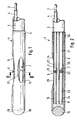
- In Fig. 1, an optical probe is generally referred to as 1. Fig. 1 does not show the complete probe, but merely the probe tip.
- A
tubing element 2 surrounds a plurality of optical fibers. In Fig. 1, only oneoptical fiber 3 is shown (for graphical purposes). Anenvelope 4 surrounds this optical fiber. -
Tubing element 2 is connected ( as will be further explained in Fig. 2) with asheath 5 which consists - in the shown example - of metal, preferably stainless steel. This sheath surrounds a plurality of sensors - two of which are shown in Fig. 1 and referred to as 6 and 7 -, each of these sensors being an integral part together with the associated optical fiber. - For the details and the operation principle of such a sensor, reference is not made to Fig. 5 which shows the details of
sensor 6 in longitudinal section. Light guided inoptical fiber 3 reaches a dye-containing gel 8, the absorption spectrum of said dye - for example, phenol red - being dependent on the pH value of the blood. The light is then reflected at reflector 9. The whole system is packed in a selective membrane orenvelope 10, this membrane being permeable for the ions or gas molecules to be measured - in case of a pH electrode, for hydrogen ions -, so that these ions/gas molecules can reach the dye-containing gel.Membrane 10 is fastened on theoptical fiber 3 and the reflector 9 by a glue 11. The preferred material formembrane 10 is a hydrophilic material such as cellulose. - Therefore, light is directed into the optical fiber in the direction of
arrow 12, passes the dye-containing gel 8 - the absorption of which depends on the parameter to be measured -, is reflected at reflector 9 (this reflector is preferably made of metal such as platinum or stainless steel, the surface of this metal being polished on the side of gel 8), passes gel 8 again and is guided back through the optical fiber as indicated byarrow 13. A monitor measures the intensity of the reflected light to determine the parameter to be measured. Preferably, the light is transmitted and received in the form of a train of light pulses, but this is not a strict requirement.Optical fiber 3 is preferably a plastic fiber to ensure that it cannot break off inside a patient's artery; furthermore, a plastic fiber may be sterilized by gamma rays. To reduce cross interferences, the selective membranes should be selected according to the parameter to be measured; e.g., the membrane surrounding a pCO₂ sensor should not be permeable to hydrogen ions, but only for gas molecules. Gel 8 is used to immobilize the respective dye. - Returning now to Fig. 1,
sheath 5 provides three openings to allow the blood to reach the diffusion zones (i.e. the region of the dye-containing gel) of the sensors. Two of theseopenings sheath 5 is closed by a metal cap 16 (this metal cap is generated by welding or soldering and is further welded or soldered to sheath 5); after welding or soldering, projecting burrs are removed by electropolishing to avoid injury of the patient's artery. Although indicated as 16′, the connection line betweenmetal cap 16 andsheath 5 is no longer visible after manufacturing. - The various sensors are fastened within
sheath 5 by means of a silicone glue or adhesive 17. Placing and distribution of this glue will be explained by means of Figs. 3 and 4. - Fig. 2 depicts a longitudinal section of the probe tip. In this section, details of the sensors (as just explained by means of Fig. 5) are shown. For example, the dye-containing gel of
pH sensor 6 is out-lined as 18, whereas its reflector is referred to as 19 and the semipermeable envelope as 20. In similar manner, 21 is the optical fiber leading to a blood gas sensor 7 (for example, a pO₂ sensor), 22 is the dye-containing gel of this sensor, 23 its reflector and 24 its semipermeable envelope (which should be permeable for gas molecules, but neither for water molecules nor for hydrogen ions in this case). Fig. 2 further depicts thethird opening 25 insheath 5. As shown by 26,tubing element 2 is introduced intosheath 5 and secured by adhesive means.Silicone glue 17 fills the space between the sensors and between the sensors and the sheath, respectively.pO₂ sensor 7 is completely embedded in this glue, whereas the outside 27 ofpH sensor 6 is not covered by the glue although its rear side is in contact with said glue. -
Openings sheath 5 are manufactured by spark errosion. Upon manufacturing, it has to be ensured that no burrs or projecting edges are created in order to avoid any injury of the wall of the patient's artery. - The details of the manufacturing process will not be explained by means of Fig. 3 which is a cross section along line III-III of Fig. 1 in enlarged scale. Within
sheath 5,pH sensor 6 andpO₂ sensor 7 and theirappropriate reflectors semi-permeable envelopes further sensor 27 is used for pCO₂ measurement; its reflector is referred to as 28 and its semi-permeable envelope as 29. This sensor is not shown in Fig. 1 because it is hidden undersheath 5. - A
wire 30 is used for strain relieving of the probe. Fastening of this sensor tometal cap 16 will be shown by means of Fig. 6. - Upon manufacturing of the probe,
sheath 5 is placed in approximately horizontal position. Then,pO₂ sensor 7,pCO₂ sensor 27,pH sensor 6 andwire 30 are introduced into the sheath such thatpH sensor 6 is on top of the other sensors and the wire. - In the next step, a silicone glue is introduced or injected into the interior of
sheath 5, e.g. through one ofopenings sheath 5 is not completely filled with glue; instead, the upmost portion is left empty.Blood gas sensors openings sheath 5 and throughsemipermeable envelopes sensors -
pH sensor 6 is not completely embedded in the silicone glue. Instead, only the lower portion of this sensor is kept in place by the glue. The upper portion ofpH sensor 6 is not covered by glue, and the silicone glue also does not tend to creep upwards. Therefore, hydrogen ions may reach thesemi-permeable envelope 20 and diffuse into the diffusion zones (i.e. the zone containing the gel). Therefore, the silicone glue does not impair the pH measurement. - On the other hand, the silicone glue is rather elastic. This ensures that the sensors can move in case of temperature changes. Further, the placement of the sensors within
sheath 5 is not critical as at least the blood gas sensors (7 and 27) must not be placed directly adjacent to one of the openings of sheath 5 (as shown by way of pCO₂ sensor 27). - Fig. 4 depicts a similar cross section of another probe. It simply illustrates that a strain relieving wire is not absolutely mandatory for such a probe. In this case, all sensors are positioned adjacent to appropriate openings of
sheath 5′. In this figure, the pH sensor is outlined as 6′, the pO₂ sensor as 7′ and the pCO₂ sensor as 27′. The silicone glue is referred to as 17′. - Fig. 6 depicts a longitudinal section of another probe tip 31 to illustrate the strain relieving means.
Sheath 32 is closed at its outer end bymetal cap 33. Astrain relieving wire 34 is welded or soldered to said cap upon welding or soldering ofmetal cap 33 tosheath 32, i.e. there is only one welding or soldering manufacturing step.Sheath 32,metal cap 33 andwire 34 are made of the same material and can be regarded as a single component after manufacturing. At the end of the cable (not shown), the wire is fastened to a connector or totubing 2. For graphical purposes, the sensors are not shown in the cross section according to Fig. 6. - Figs. 7 and 8 are used to illustrate the effect of sterilization at low temperatures on sensor intensity.
- Fig. 7 relates to a pH sensor after cryogamma sterilization. The horizontal axis shows a relation k which is the proportion of sensor intensity after sterilization to the sensor intensity before sterilization, i.e.

The vertical axis shows the amount of sensors n (k) for a factor k′ between k and k+ 0.1, i.e.

The test was carried out with 22 probes with fastening of the sensor inside the sheath by ordinary glue, in this case a PUR glue, and further with seven sensors using silicone glue. The obtained function n(k) for the case of PUR glue is depicted in a broken line and labeled as 35. The corresponding function for probes with silicone glue is labeled as 36 and hatched. - It is evident that the cryogamma sterilization has a considerably smaller effect on probes which are manufactured using silicone glue than on probes which are manufactured using ordinary glue. In particular, the average factor is
k = 0.74
in the case of probes with ordinary glue and
k = 0.87
in the case or probes with silicone glue. - A major reason for the better predictability of sensor intensity after cryogamma sterilization when using a silicone glue is that such a glue provides increased elasticity. As shown by way of Fig. 7, this is even true in the case of a pH sensor which is only partially covered by the silicone glue.
- Fig. 8 shows a similar example of the function n(k) for a pCO₂ sensor. In this figure, only the
function 37 for a silicone glue-manufactured probe is shown. A test with fourteen probes revealed a very impressing average value of
k = 0.96.
Claims (5)
- Method for manufacturing an optical probe for the invasive measurement of blood parameters, said optical probe comprising at least one sensor (7,27) sensitive to a blood gas parameter such as pO₂ or pCO₂ and at least one additional sensor (6) sensitive to the pH value of the blood, said sensors having selective membranes (24,29,20), and said optical probe further comprising a sheath (5) at least partially covering said sensors (7,27,6) and fastened on said sensor by a glue,
said method comprising the following manufacturing steps:(1) The sheath (5) is placed in an approximately horizontal position,(2) the sensors (7,27,6) are introduced into the sheath (5) such that(2.1) the pH sensor (6) is in the top position, whereas(2.2) the blood gas sensors (7,27) are placed below the pH sensor (6),(3) a glue which allows diffusion of gas molecules in its hardened state is introduced into the sheath (5) such that the upmost portion of the, sheath (5) is left empty and the pH sensor is not totally covered by said glue. - Method according to claim 1, characterized in that said glue is a silicone glue (17).
- Optical probe for the invasive measurement of blood parameters comprising at least one sensor (7,27) sensitive to a blood gas parameter such as pO₂ or pCO₂, said sensor having a diffusion zone covered by a selective membrane (24,29), and said optical probe further comprising a sheath (5) at least partially covering said sensor (7,27) and fastened on said sensor (7,27) by a glue, said glue being a silicone glue (17).
- Optical probe according to claim 3 with an additional sensor (6) sensitive to the pH value of the blood, characterized in that said silicone glue (17) covers the selective membrane (20) of the pH sensor (6) only partially, whereas it covers the selective membrane (24, 29) of the blood gas sensitive sensor (7,27) completely or almost completely.
- Optical probe according to claim 3 or 4, characterized in that it comprises two or more blood gas sensors (7,27) and/or a wire (30,34) which is connected to a metal cap (16,33) fixed on the top of said sheath (5,32).
Priority Applications (8)
| Application Number | Priority Date | Filing Date | Title |
|---|---|---|---|
| EP88105676A EP0336985B1 (en) | 1988-04-09 | 1988-04-09 | Method for manufacturing an optical probe |
| DE8888105676T DE3877949T2 (en) | 1988-04-09 | 1988-04-09 | MANUFACTURING METHOD FOR AN OPTICAL PROBE. |
| US07/332,080 US5005576A (en) | 1988-04-09 | 1989-03-30 | Optical probe |
| JP1089595A JPH01310642A (en) | 1988-04-09 | 1989-04-07 | Optical probe and its production |
| CA000596061A CA1330830C (en) | 1988-04-09 | 1989-04-07 | Method for manufacturing an optical probe |
| CN89102188A CN1018980B (en) | 1988-04-09 | 1989-04-08 | Optical probe and its manufacturing method |
| KR1019890004689A KR890016383A (en) | 1988-04-09 | 1989-04-08 | Manufacturing method of optical probe |
| SG54993A SG54993G (en) | 1988-04-09 | 1993-04-29 | Method for manufacturing an optical probe |
Applications Claiming Priority (1)
| Application Number | Priority Date | Filing Date | Title |
|---|---|---|---|
| EP88105676A EP0336985B1 (en) | 1988-04-09 | 1988-04-09 | Method for manufacturing an optical probe |
Publications (2)
| Publication Number | Publication Date |
|---|---|
| EP0336985A1 EP0336985A1 (en) | 1989-10-18 |
| EP0336985B1 true EP0336985B1 (en) | 1993-01-27 |
Family
ID=8198874
Family Applications (1)
| Application Number | Title | Priority Date | Filing Date |
|---|---|---|---|
| EP88105676A Expired - Lifetime EP0336985B1 (en) | 1988-04-09 | 1988-04-09 | Method for manufacturing an optical probe |
Country Status (8)
| Country | Link |
|---|---|
| US (1) | US5005576A (en) |
| EP (1) | EP0336985B1 (en) |
| JP (1) | JPH01310642A (en) |
| KR (1) | KR890016383A (en) |
| CN (1) | CN1018980B (en) |
| CA (1) | CA1330830C (en) |
| DE (1) | DE3877949T2 (en) |
| SG (1) | SG54993G (en) |
Cited By (2)
| Publication number | Priority date | Publication date | Assignee | Title |
|---|---|---|---|---|
| US6999809B2 (en) | 2002-07-16 | 2006-02-14 | Edwards Lifesciences Corporation | Central venous catheter having a soft tip and fiber optics |
| US7029467B2 (en) | 2002-07-16 | 2006-04-18 | Edwards Lifesciences Corporation | Multiple lumen catheter having a soft tip |
Families Citing this family (42)
| Publication number | Priority date | Publication date | Assignee | Title |
|---|---|---|---|---|
| AT393326B (en) * | 1988-08-02 | 1991-09-25 | Avl Verbrennungskraft Messtech | INDICATOR SUBSTANCE FOR A MEASURING DEVICE FOR THE OPTICAL DETERMINATION OF INTERESTING PARAMETERS OF A SAMPLE AND MEASURING PROCEDURE THEREFOR |
| US5047627A (en) * | 1990-05-18 | 1991-09-10 | Abbott Laboratories | Configuration fiber-optic blood gas sensor bundle and method of making |
| US5124130A (en) * | 1990-05-22 | 1992-06-23 | Optex Biomedical, Inc. | Optical probe |
| US5054882A (en) * | 1990-08-10 | 1991-10-08 | Puritan-Bennett Corporation | Multiple optical fiber event sensor and method of manufacture |
| DE69023496T2 (en) * | 1990-08-13 | 1996-03-21 | Hewlett Packard Gmbh | Optical probe. |
| EP0476161A1 (en) * | 1990-09-17 | 1992-03-25 | Hewlett-Packard GmbH | Optical probe |
| US5176882A (en) * | 1990-12-06 | 1993-01-05 | Hewlett-Packard Company | Dual fiberoptic cell for multiple serum measurements |
| US5320814A (en) * | 1991-01-25 | 1994-06-14 | Trustees Of Tufts College | Fiber optic array sensors, apparatus, and methods for concurrently visualizing and chemically detecting multiple analytes of interest in a fluid sample |
| US5250264A (en) * | 1991-01-25 | 1993-10-05 | Trustees Of Tufts College | Method of making imaging fiber optic sensors to concurrently detect multiple analytes of interest in a fluid sample |
| US5244636A (en) * | 1991-01-25 | 1993-09-14 | Trustees Of Tufts College | Imaging fiber optic array sensors, apparatus, and methods for concurrently detecting multiple analytes of interest in a fluid sample |
| US5119463A (en) * | 1991-04-09 | 1992-06-02 | Abbott Laboratories | Compound optical probe employing single optical waveguide |
| WO1992019150A1 (en) * | 1991-05-03 | 1992-11-12 | Innerspace, Inc. | Direct insertable tissue probe |
| DE4218321A1 (en) * | 1991-12-09 | 1993-06-17 | Siemens Ag | DIAGNOSTIC SYSTEM |
| US5335305A (en) * | 1991-12-19 | 1994-08-02 | Optex Biomedical, Inc. | Optical sensor for fluid parameters |
| US5280786A (en) * | 1992-01-21 | 1994-01-25 | Fiberoptic Sensor Technologies, Inc. | Fiberoptic blood pressure and oxygenation sensor |
| US5333609A (en) * | 1992-05-19 | 1994-08-02 | Minnesota Mining And Manufacturing Company | Catheter and probe-catheter assembly |
| US5257338A (en) | 1992-05-22 | 1993-10-26 | Biomedical Sensors, Ltd. | Device for transmitting and returning light and apparatus and method of manufacture |
| EP0571184A3 (en) * | 1992-05-22 | 1995-01-25 | Puritan Bennett Corp | Reinforced catheter probe. |
| US5280130A (en) * | 1992-05-22 | 1994-01-18 | Biomedical Sensors, Ltd. | Assembly of a tube and a part and apparatus and method of manufacture |
| AT397458B (en) * | 1992-09-25 | 1994-04-25 | Avl Verbrennungskraft Messtech | SENSOR ARRANGEMENT |
| WO1994010553A1 (en) * | 1992-10-23 | 1994-05-11 | Optex Biomedical, Inc. | Fibre-optic probe for the measurement of fluid parameters |
| DE20012237U1 (en) | 1999-07-26 | 2000-10-12 | Storz Karl Gmbh & Co Kg | Medical instrument with a contactlessly readable information carrier |
| US20020128542A1 (en) * | 2001-03-09 | 2002-09-12 | Van Over James E. | Physiological monitor for veterinary and human medical use and method |
| US7838296B2 (en) * | 2002-08-28 | 2010-11-23 | Separation Technology, Inc. | Methods and apparatus for ultrasonic determination of red blood cell indices |
| US7142901B2 (en) * | 2002-09-25 | 2006-11-28 | Masimo Corporation | Parameter compensated physiological monitor |
| US7274955B2 (en) * | 2002-09-25 | 2007-09-25 | Masimo Corporation | Parameter compensated pulse oximeter |
| DE10311452B4 (en) * | 2003-03-15 | 2006-04-13 | Roche Diagnostics Gmbh | Analysis system for the reagent-free determination of the concentration of an analyte in living tissue |
| GB0505036D0 (en) | 2005-03-11 | 2005-04-20 | Oxford Optronix Ltd | An optical measurement sensor |
| CN100355390C (en) * | 2005-03-15 | 2007-12-19 | 深圳迈瑞生物医疗电子股份有限公司 | Method of blood oxygen probe sealing wire of silica gel finger sleeve and its mold |
| US8409864B2 (en) * | 2006-01-06 | 2013-04-02 | Renal Solutions, Inc. | Ammonia sensor and system for use |
| WO2007105805A1 (en) * | 2006-03-10 | 2007-09-20 | Kawasumi Laboratories, Inc. | Blood characteristics measuring probe, cardiovascular system artificial organ and artificial lung |
| DK2989975T3 (en) | 2007-02-06 | 2018-09-24 | Medtronic Minimed Inc | OPTICAL SYSTEMS AND PROCEDURES FOR RATIOMETRIC MEASUREMENT OF BLOOD GLUCOSE CONCENTRATION |
| CA2686065A1 (en) | 2007-05-10 | 2008-11-20 | Glumetrics, Inc. | Equilibrium non-consuming fluorescence sensor for real time intravascular glucose measurement |
| WO2009067626A1 (en) | 2007-11-21 | 2009-05-28 | Glumetrics, Inc. | Use of an equilibrium intravascular sensor to achieve tight glycemic control |
| WO2009129186A2 (en) * | 2008-04-17 | 2009-10-22 | Glumetrics, Inc. | Sensor for percutaneous intravascular deployment without an indwelling cannula |
| WO2011041546A1 (en) | 2009-09-30 | 2011-04-07 | Glumetrics, Inc. | Sensors with thromboresistant coating |
| US8467843B2 (en) * | 2009-11-04 | 2013-06-18 | Glumetrics, Inc. | Optical sensor configuration for ratiometric correction of blood glucose measurement |
| WO2011075710A1 (en) * | 2009-12-17 | 2011-06-23 | Glumetrics, Inc. | Identification of aberrant measurements of in vivo glucose concentration using temperature |
| US8694069B1 (en) * | 2009-12-21 | 2014-04-08 | Kosense, LLC | Fiber-optic probe with embedded peripheral sensors for in-situ continuous monitoring |
| CN102175276B (en) * | 2011-01-24 | 2012-06-27 | 中国科学院半导体研究所 | Ultralow-temperature high-vacuum fiber sensor probe |
| GB201210439D0 (en) * | 2012-06-13 | 2012-07-25 | Softcell Medicals | Apparatus |
| WO2018022916A1 (en) * | 2016-07-29 | 2018-02-01 | Los Angeles Biomedical Research Institute At Harbor Ucla Medical Center | Integrated fiber optic sensor umbilical catheter |
Family Cites Families (4)
| Publication number | Priority date | Publication date | Assignee | Title |
|---|---|---|---|---|
| US3674013A (en) * | 1970-09-30 | 1972-07-04 | American Optical Corp | Fiberoptic catheter |
| US4557900A (en) * | 1982-09-28 | 1985-12-10 | Cardiovascular Devices, Inc. | Optical sensor with beads |
| JPS60231156A (en) * | 1984-04-30 | 1985-11-16 | Kuraray Co Ltd | Liquid junction type reference electrode |
| DE3760300D1 (en) * | 1987-02-17 | 1989-08-17 | Hewlett Packard Gmbh | Method for manufacturing a measuring probe |
-
1988
- 1988-04-09 EP EP88105676A patent/EP0336985B1/en not_active Expired - Lifetime
- 1988-04-09 DE DE8888105676T patent/DE3877949T2/en not_active Expired - Fee Related
-
1989
- 1989-03-30 US US07/332,080 patent/US5005576A/en not_active Expired - Fee Related
- 1989-04-07 JP JP1089595A patent/JPH01310642A/en active Pending
- 1989-04-07 CA CA000596061A patent/CA1330830C/en not_active Expired - Fee Related
- 1989-04-08 KR KR1019890004689A patent/KR890016383A/en not_active Application Discontinuation
- 1989-04-08 CN CN89102188A patent/CN1018980B/en not_active Expired
-
1993
- 1993-04-29 SG SG54993A patent/SG54993G/en unknown
Non-Patent Citations (2)
| Title |
|---|
| "Macromolecular Biomaterials", Garth W Hastings et al, CRC Press Inc., Florida USA * |
| IEEE Transactions on Biomedical Engineering vol.BME-33, no.2, February 1986, New York, USA, pages 117-132; JL Gehrich et al: "Optical fluorescence and its application to an intravascular blood gas monitoring system" * |
Cited By (2)
| Publication number | Priority date | Publication date | Assignee | Title |
|---|---|---|---|---|
| US6999809B2 (en) | 2002-07-16 | 2006-02-14 | Edwards Lifesciences Corporation | Central venous catheter having a soft tip and fiber optics |
| US7029467B2 (en) | 2002-07-16 | 2006-04-18 | Edwards Lifesciences Corporation | Multiple lumen catheter having a soft tip |
Also Published As
| Publication number | Publication date |
|---|---|
| DE3877949D1 (en) | 1993-03-11 |
| EP0336985A1 (en) | 1989-10-18 |
| CN1036830A (en) | 1989-11-01 |
| KR890016383A (en) | 1989-11-29 |
| CN1018980B (en) | 1992-11-11 |
| SG54993G (en) | 1993-07-09 |
| CA1330830C (en) | 1994-07-19 |
| JPH01310642A (en) | 1989-12-14 |
| DE3877949T2 (en) | 1993-05-19 |
| US5005576A (en) | 1991-04-09 |
Similar Documents
| Publication | Publication Date | Title |
|---|---|---|
| EP0336985B1 (en) | Method for manufacturing an optical probe | |
| EP0336984A1 (en) | Measuring probe | |
| US5605152A (en) | Optical glucose sensor | |
| US5582170A (en) | Fiber optic sensor for in vivo measurement of nitric oxide | |
| CA1121242A (en) | Fiber optic ph probe | |
| US4800886A (en) | Sensor for measuring the concentration of a gaseous component in a fluid by absorption | |
| US5039492A (en) | Optical pH and gas concentration sensor | |
| CA2019511C (en) | Method of and apparatus for determining the similarity of a biological analyte from known biological fluids | |
| US5421328A (en) | Intravascular blood parameter sensing system | |
| DK170510B1 (en) | Sensor system and method for determining the pH of a liquid by means of the sensor system | |
| Vurek et al. | A fiber optic PCO 2 sensor | |
| JPH0433456B2 (en) | ||
| US4900381A (en) | Method for manufacturing a measuring probe | |
| CA2080472A1 (en) | Infrared and near-infrared testing of blood constituents | |
| US8095196B2 (en) | Microsensor needle for pH measurement in tissue | |
| JPH05115468A (en) | Sensor for phenomenon of multiplex optical fiber and production thereof | |
| JP2628355B2 (en) | Fiber optic probe connector for physiological measurement devices | |
| EP0471861B1 (en) | Optical probe | |
| Scheggi | Optical fiber sensors in medicine | |
| US5383453A (en) | Method for manufacturing an optical probe | |
| WO2004026127A1 (en) | Improvements in or relating to neonatal sensor devices | |
| Schlain et al. | Continuous arterial blood gas monitoring with transmitted light sensors and light emitting diode light sources | |
| Proctor et al. | Colorimetric blood-gas monitoring sensors | |
| Atwater et al. | Technological advances in pressure monitoring | |
| WO2004058057A1 (en) | Sensor device for monitoring perfusion of tissue |
Legal Events
| Date | Code | Title | Description |
|---|---|---|---|
| PUAI | Public reference made under article 153(3) epc to a published international application that has entered the european phase |
Free format text: ORIGINAL CODE: 0009012 |
|
| 17P | Request for examination filed |
Effective date: 19890118 |
|
| AK | Designated contracting states |
Kind code of ref document: A1 Designated state(s): DE FR GB |
|
| 17Q | First examination report despatched |
Effective date: 19911205 |
|
| GRAA | (expected) grant |
Free format text: ORIGINAL CODE: 0009210 |
|
| AK | Designated contracting states |
Kind code of ref document: B1 Designated state(s): DE FR GB |
|
| REF | Corresponds to: |
Ref document number: 3877949 Country of ref document: DE Date of ref document: 19930311 |
|
| ET | Fr: translation filed | ||
| PLBE | No opposition filed within time limit |
Free format text: ORIGINAL CODE: 0009261 |
|
| STAA | Information on the status of an ep patent application or granted ep patent |
Free format text: STATUS: NO OPPOSITION FILED WITHIN TIME LIMIT |
|
| 26N | No opposition filed | ||
| PGFP | Annual fee paid to national office [announced via postgrant information from national office to epo] |
Ref country code: GB Payment date: 19940330 Year of fee payment: 7 |
|
| PGFP | Annual fee paid to national office [announced via postgrant information from national office to epo] |
Ref country code: FR Payment date: 19940427 Year of fee payment: 7 |
|
| PGFP | Annual fee paid to national office [announced via postgrant information from national office to epo] |
Ref country code: DE Payment date: 19940510 Year of fee payment: 7 |
|
| PG25 | Lapsed in a contracting state [announced via postgrant information from national office to epo] |
Ref country code: GB Effective date: 19950409 |
|
| GBPC | Gb: european patent ceased through non-payment of renewal fee |
Effective date: 19950409 |
|
| PG25 | Lapsed in a contracting state [announced via postgrant information from national office to epo] |
Ref country code: FR Effective date: 19951229 |
|
| PG25 | Lapsed in a contracting state [announced via postgrant information from national office to epo] |
Ref country code: DE Effective date: 19960103 |
|
| REG | Reference to a national code |
Ref country code: FR Ref legal event code: ST |