EP0336903B1 - Sluice guide in an union joint for hoses for a catheter arrangement - Google Patents
Sluice guide in an union joint for hoses for a catheter arrangement Download PDFInfo
- Publication number
- EP0336903B1 EP0336903B1 EP89810247A EP89810247A EP0336903B1 EP 0336903 B1 EP0336903 B1 EP 0336903B1 EP 89810247 A EP89810247 A EP 89810247A EP 89810247 A EP89810247 A EP 89810247A EP 0336903 B1 EP0336903 B1 EP 0336903B1
- Authority
- EP
- European Patent Office
- Prior art keywords
- elastomeric member
- lock according
- introduction lock
- hose connector
- elastomeric
- Prior art date
- Legal status (The legal status is an assumption and is not a legal conclusion. Google has not performed a legal analysis and makes no representation as to the accuracy of the status listed.)
- Expired - Lifetime
Links
- 0 *CC1C2C3C4*1CC4C1C3C1C2 Chemical compound *CC1C2C3C4*1CC4C1C3C1C2 0.000 description 1
Images
Classifications
-
- F—MECHANICAL ENGINEERING; LIGHTING; HEATING; WEAPONS; BLASTING
- F16—ENGINEERING ELEMENTS AND UNITS; GENERAL MEASURES FOR PRODUCING AND MAINTAINING EFFECTIVE FUNCTIONING OF MACHINES OR INSTALLATIONS; THERMAL INSULATION IN GENERAL
- F16L—PIPES; JOINTS OR FITTINGS FOR PIPES; SUPPORTS FOR PIPES, CABLES OR PROTECTIVE TUBING; MEANS FOR THERMAL INSULATION IN GENERAL
- F16L37/00—Couplings of the quick-acting type
- F16L37/02—Couplings of the quick-acting type in which the connection is maintained only by friction of the parts being joined
- F16L37/04—Couplings of the quick-acting type in which the connection is maintained only by friction of the parts being joined with an elastic outer part pressing against an inner part by reason of its elasticity
- F16L37/05—Couplings of the quick-acting type in which the connection is maintained only by friction of the parts being joined with an elastic outer part pressing against an inner part by reason of its elasticity tightened by the pressure of a mechanical element
-
- A—HUMAN NECESSITIES
- A61—MEDICAL OR VETERINARY SCIENCE; HYGIENE
- A61M—DEVICES FOR INTRODUCING MEDIA INTO, OR ONTO, THE BODY; DEVICES FOR TRANSDUCING BODY MEDIA OR FOR TAKING MEDIA FROM THE BODY; DEVICES FOR PRODUCING OR ENDING SLEEP OR STUPOR
- A61M25/00—Catheters; Hollow probes
- A61M25/01—Introducing, guiding, advancing, emplacing or holding catheters
- A61M25/0105—Steering means as part of the catheter or advancing means; Markers for positioning
- A61M25/013—One-way gripping collars
-
- A—HUMAN NECESSITIES
- A61—MEDICAL OR VETERINARY SCIENCE; HYGIENE
- A61M—DEVICES FOR INTRODUCING MEDIA INTO, OR ONTO, THE BODY; DEVICES FOR TRANSDUCING BODY MEDIA OR FOR TAKING MEDIA FROM THE BODY; DEVICES FOR PRODUCING OR ENDING SLEEP OR STUPOR
- A61M39/00—Tubes, tube connectors, tube couplings, valves, access sites or the like, specially adapted for medical use
- A61M39/02—Access sites
- A61M39/06—Haemostasis valves, i.e. gaskets sealing around a needle, catheter or the like, closing on removal thereof
- A61M39/0606—Haemostasis valves, i.e. gaskets sealing around a needle, catheter or the like, closing on removal thereof without means for adjusting the seal opening or pressure
-
- A—HUMAN NECESSITIES
- A61—MEDICAL OR VETERINARY SCIENCE; HYGIENE
- A61M—DEVICES FOR INTRODUCING MEDIA INTO, OR ONTO, THE BODY; DEVICES FOR TRANSDUCING BODY MEDIA OR FOR TAKING MEDIA FROM THE BODY; DEVICES FOR PRODUCING OR ENDING SLEEP OR STUPOR
- A61M39/00—Tubes, tube connectors, tube couplings, valves, access sites or the like, specially adapted for medical use
- A61M39/02—Access sites
- A61M39/06—Haemostasis valves, i.e. gaskets sealing around a needle, catheter or the like, closing on removal thereof
- A61M39/0613—Haemostasis valves, i.e. gaskets sealing around a needle, catheter or the like, closing on removal thereof with means for adjusting the seal opening or pressure
-
- A—HUMAN NECESSITIES
- A61—MEDICAL OR VETERINARY SCIENCE; HYGIENE
- A61M—DEVICES FOR INTRODUCING MEDIA INTO, OR ONTO, THE BODY; DEVICES FOR TRANSDUCING BODY MEDIA OR FOR TAKING MEDIA FROM THE BODY; DEVICES FOR PRODUCING OR ENDING SLEEP OR STUPOR
- A61M39/00—Tubes, tube connectors, tube couplings, valves, access sites or the like, specially adapted for medical use
- A61M39/02—Access sites
- A61M39/06—Haemostasis valves, i.e. gaskets sealing around a needle, catheter or the like, closing on removal thereof
- A61M2039/062—Haemostasis valves, i.e. gaskets sealing around a needle, catheter or the like, closing on removal thereof used with a catheter
-
- A—HUMAN NECESSITIES
- A61—MEDICAL OR VETERINARY SCIENCE; HYGIENE
- A61M—DEVICES FOR INTRODUCING MEDIA INTO, OR ONTO, THE BODY; DEVICES FOR TRANSDUCING BODY MEDIA OR FOR TAKING MEDIA FROM THE BODY; DEVICES FOR PRODUCING OR ENDING SLEEP OR STUPOR
- A61M39/00—Tubes, tube connectors, tube couplings, valves, access sites or the like, specially adapted for medical use
- A61M39/02—Access sites
- A61M39/06—Haemostasis valves, i.e. gaskets sealing around a needle, catheter or the like, closing on removal thereof
- A61M2039/0673—Haemostasis valves, i.e. gaskets sealing around a needle, catheter or the like, closing on removal thereof comprising means actively pressing on the device passing through the seal, e.g. inflatable seals, diaphragms, clamps
Definitions
- the invention relates to an introducer for a catheter arrangement according to the preamble of independent patent claim 1.
- a hose connector in which there is an O-ring made of silicone rubber, through which a carrier hose of the catheter arrangement is inserted liquid-tight.
- a radial seal is also arranged, which encloses the elongated guide body, which is much thinner than the carrier hose, in a pressure-tight manner.
- an introductory sheath for a catheter arrangement which has a plurality of flat sealing bodies arranged one behind the other and which have different through openings. Each sealing body is tuned to a certain diameter, so that only one of these sealing bodies encloses the elongated body inserted into the lock.
- the invention has for its object to provide an introductory lock of the type mentioned, which reliably and automatically seals significantly different bodies in diameter.
- the sealing body encloses bodies that pass through with a diameter of about 1 mm to about 6 mm in a pressure-tight manner and connects the outlet of vascular fluid when a catheter is inserted or changed. Since the insertion lock according to the invention has only one sealing body, the assembly is much easier and less prone to errors than the previously known insertion locks. A major advantage is that the seal seals in a range of approximately 1 mm to 6 mm in a stepless and self-adapting manner and that the catheter that passes through can be moved in the longitudinal direction with little force. The introducer sheath according to the invention thus simplifies the handling of the catheter arrangement.
- a sealing body made of silicone rubber has particularly good sealing properties.
- the hardness of the sealing body should be less than 40 Shore.
- a body with a hardness of around 20 Shore has proven particularly useful.
- the catheter arrangement has a tube connecting piece 21, to which an insertion tube 2, a so-called introducer, is fastened by means of a union nut 17, which introduces a guide wire 18 (FIG. 3a-3b) known per se the vessel to be treated enables.
- the hose connector 21 has a housing 5 with a passage 12 with a circular cross section, into which a rubber-elastic sealing body 7 and a comparatively hard sleeve 6 are inserted.
- a lateral passage 14 opens into the passage 12, into which a hose 3 is inserted, through which, for example, a dilatation balloon can be connected to a suction and pressure pump.
- the length of the passage 12 is dimensioned so that after screwing on a lid 4 of the sealing body 7 with a front surface and a rear surface 8 'on corresponding flat surfaces 13 and 9 of the housing or the sleeve 6 abuts.
- the sealing body 7 has a passage 20, which has a narrow portion 11 in the center with a width of approximately 1 mm, from which the passage 20 widens on both sides and the conical surfaces 10 with a half opening angle of about 20 °.
- the constriction 11 is dimensioned such that a thin guide body 18 passing through the passage is enclosed in a pressure-tight manner by the sealing body 7. In the rest position, the width of the constriction 11 is approximately 1 mm, which can also be smaller if even thinner guide bodies are used.
- the lateral surface 22 of the sealing body 7 is approximately parallel to the inner surface 10, so that the body 7 has approximately the same wall thickness everywhere.
- the body 7 is preferably made of silicone rubber with a hardness below 40 Shore, preferably about 20 Shore.
- a substantially thicker hose 19 for example with a diameter of 6 mm, is pushed onto the guide body 18, there is a comparatively wide contact area between the sealing body 7 and the hose 19 and a radial displacement, in particular of the central region of the body 7 outward. Since the body 7 is only supported at the front and rear on the surfaces 8 and 8 ', it can be displaced in the central area without generating large radial forces and while avoiding uncontrolled deformations. The comparatively thick hose 19 can therefore be moved in the longitudinal direction with little friction in the body 7.
- the sealing body 11 is preferably mirror-symmetrical to a transverse surface bisecting it and rotationally symmetrical with respect to its longitudinal axis. It can therefore not be used upside down in the housing 5. It also exerts equally large forces on the catheter when it is pushed in and out.
- a rubber-elastic ring 23 with a circular profile cross section is preferably placed around the rubber-elastic body 7, in particular if the body 7 is made of polyurethane. Tests have shown that crack formation on the body 7 can be avoided in this way, even under very heavy loads and with a radial expansion of 400%.
- the ring 23 can be made of rubber and encompasses the body 7 at its narrowest point as shown. The ring 23 supports the immediate contraction of the body 7 when changing the catheter.
Description
Die Erfindung betrifft eine Einführungsschleuse für eine Katheteranordnung nach dem Oberbegriff des unabhängigen Patentanspruchs 1.The invention relates to an introducer for a catheter arrangement according to the preamble of
Eine Einführungsschleuse dieser Art ist durch die US-A-4,252,122 bekannt geworden. Diese weist einen zylindrischen Dichtungskörper auf, dessen Durchgang durch achsiales Quetschen mittels eines schraubbaren Deckels vermutlich im Durchmesser etwas geändert werden kann. Eine Anpassung an grosse Durchmesserunterschiede, wie sie beispielsweise beim Austausch eines Führungsdrahtes mit einem Durchmesser von 1 mm gegen einen Ballondilationskatheter mit einem Durchmesser von 6 mm notwendig ist, ist hier nicht möglich. Auch ist eine Manipulation an der Einführungsschleuse, die auch beim Quetschbinder nach der EP-A-0190388 notwendig wäre, nicht erwünscht.An introductory sheath of this type is known from US-A-4,252,122. This has a cylindrical sealing body, the passage of which can presumably be slightly changed in diameter by axial crushing by means of a screwable cover. An adaptation to large differences in diameter, such as is necessary, for example, when exchanging a guide wire with a diameter of 1 mm for a balloon dilatation catheter with a diameter of 6 mm, is not possible here. Manipulation on the insertion lock, which would also be necessary in the case of the crimp binder according to EP-A-0190388, is also not desired.
Weiter ist durch die CH-A-654214 ein Schlauchverbindungsstück bekannt, in dem sich ein O-Ring aus Silikongummi befindet, durch den ein Trägerschlauch der Katheteranordnung flüssigkeitsdicht hindurchgesteckt ist. In einem weiteren Schlauchverbindungsstück ist ebenfalls eine radiale Dichtung angeordnet, die den länglichen Führungskörper, der wesentlich dünner ist als der Trägerschlauch, druckdicht umschliesst.Furthermore, from CH-A-654214 a hose connector is known in which there is an O-ring made of silicone rubber, through which a carrier hose of the catheter arrangement is inserted liquid-tight. In a further hose connector, a radial seal is also arranged, which encloses the elongated guide body, which is much thinner than the carrier hose, in a pressure-tight manner.
Bekannt ist ausserdem eine Einführungsschleuse für eine Katheteranordnung, die mehrere hintereinander angeordnete flache Dichtungskörper aufweist, die unterschiedliche Durchführungsöffnungen aufweisen. Jeder Dichtungskörper ist auf einen bestimmten Durchmesser abgestimmt, so dass jeweils nur einer dieser Dichtungskörper den in die Schleuse eingeführten länglichen Körper umschliesst.Also known is an introductory sheath for a catheter arrangement which has a plurality of flat sealing bodies arranged one behind the other and which have different through openings. Each sealing body is tuned to a certain diameter, so that only one of these sealing bodies encloses the elongated body inserted into the lock.
In der Praxis erwiesen sich diese Schleusen oft als undicht. Auch setzen diese Dichtungskörper eine hohe Präzision und eine einwandfreie Montage voraus und sind deshalb vergleichsweise teuer.In practice, these locks often proved to be leaking. These sealing bodies also require high precision and perfect assembly and are therefore comparatively expensive.
Der Erfindung liegt die Aufgabe zugrunde, eine Einführungsschleuse der eingangs genannten Gattung zu schaffen, die auch im Durchmesser wesentlich unterschiedliche Körper zuverlässig und selbstätig abdichtet.The invention has for its object to provide an introductory lock of the type mentioned, which reliably and automatically seals significantly different bodies in diameter.
Die Aufgabe wird durch die Erfindung gemäss des gekennzeichneten Teils des Anspruch 1 gelöst.The object is achieved by the invention according to the marked part of
Der Dichtungskörper umschliesst hindurchtretende Körper mit einem Durchmesser von etwa 1 mm bis etwa 6 mm druckdicht und verbindet den Austritt von Gefässflüssigkeit bei der Einführung oder dem Wechsel eines Katheters. Da die erfindungsgemässe Einführungsschleuse lediglich einen Dichtungskörper aufweist, ist die Montage wesentlich einfacher und weniger fehleranfällig als die bisher bekannten Einführungsschleusen. Ein wesentlicher Vorteil ist, dass die Dichtung im Bereich von etwa 1 mm bis 6 mm stufenlos und selbstanpassend dichtet und zudem der durchtretende Katheter mit geringer Kraft in Längsrichtung bewegt werden kann. Die erfindungsgemässe Einführungsschleuse erleichtert somit die Handhabung der Katheteranordnung.The sealing body encloses bodies that pass through with a diameter of about 1 mm to about 6 mm in a pressure-tight manner and connects the outlet of vascular fluid when a catheter is inserted or changed. Since the insertion lock according to the invention has only one sealing body, the assembly is much easier and less prone to errors than the previously known insertion locks. A major advantage is that the seal seals in a range of approximately 1 mm to 6 mm in a stepless and self-adapting manner and that the catheter that passes through can be moved in the longitudinal direction with little force. The introducer sheath according to the invention thus simplifies the handling of the catheter arrangement.
Durch die Weiterbildung nach Anspruch 2 ist es möglich, auch Katheter mit sehr grossen Durchmesserunterschieden zu verwenden, wobei bei leichter Verschiebbarkeit des Katheters die Druckdichtigkeit gewährleistet ist.Due to the development according to
Vorteilhafte Halterungen des Dichtungskörpers werden durch die Weiterbildungen nach den Ansprüchen 3 und 4 realisiert.Advantageous mounts of the sealing body are realized by the developments according to
Besonders gute Dichtungseigenschaften weist ein Dichtungskörper aus Silikongummi auf. Die Härte des Dichtungskörpers sollte weniger als 40 Shore betragen. Bewährt hat sich besonders ein Körper mit einer Härte von etwa 20 Shore.A sealing body made of silicone rubber has particularly good sealing properties. The hardness of the sealing body should be less than 40 Shore. A body with a hardness of around 20 Shore has proven particularly useful.
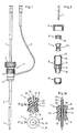
Ein Ausführungsbeispiel der Erfindung wird nachfolgend anhand der Zeichnung näher erläutert. Es zeigen:
- Fig. 1
- eine Ansicht einer Katheteranordnung,
- Fig. 2
- einen Längsschnitt durch ein Schlauchverbindungsstück mit auseinandergezogenen Teilen,
- Fig. 3a
- und Fig. 3b einen Längsschnitt und eine Ansicht eines Dichtungskörpers mit einem eingeführten Führungsdraht, und
- Fig. 3c
- einen Längsschnitt durch einen Dichtungskörper mit einem eingeführten Katheter.
An embodiment of the invention is explained below with reference to the drawing. Show it:
- Fig. 1
- 2 shows a view of a catheter arrangement,
- Fig. 2
- a longitudinal section through a hose connector with parts pulled apart,
- Fig. 3a
- and FIG. 3b shows a longitudinal section and a view of a sealing body with an inserted guide wire, and
- Fig. 3c
- a longitudinal section through a sealing body with an inserted catheter.
Wie die Figuren 1 und 2 zeigen, weist die Katheteranordnung ein Schlauchverbindungsstück 21 auf, an dem mittels einer Ueberwurfmutter 17 ein Einführungsschlauch 2, ein sogenannter Introducer, befestigt ist, der die Einführung eines an sich bekannten Führungsdrahtes 18 (Fig. 3a-3b) in das zu behandelnde Gefäss ermöglicht. Das Schlauchverbindungsstück 21 besitzt ein Gehäuse 5 mit einem im Querschnitt kreisrunden Durchgang 12, in den ein gummielastischer Dichtungskörper 7 und eine vergleichsweise harte Hülse 6 eingesetzt sind. In den Durchgang 12 mündet ein seitlicher Durchgang 14, in den ein Schlauch 3 eingesetzt ist, durch den beispielsweise ein Dilatationsballon mit einer Saug- und Druckpumpe verbunden werden kann.As FIGS. 1 and 2 show, the catheter arrangement has a
Die Länge des Durchgangs 12 ist so bemessen, dass nach dem Aufschrauben eines Deckels 4 der Dichtungskörper 7 mit einer vorderen Fläche und einer hinteren Fläche 8′ an entsprechenden ebenen Flächen 13 und 9 des Gehäuses bzw. der Hülse 6 anliegt. Wie die Fig. 3a deutlich zeigt, weist der Dichtungskörper 7 einen Durchgang 20 auf, der mittig eine Engstelle 11 mit einer Weite von etwa 1 mm besitzt, von der aus sich der Durchgang 20 nach beiden Seiten erweitert und der Kegelflächen 10 mit einem halben Oeffnungswinkel von etwa 20° bildet.The length of the
Die Engstelle 11 ist so bemessen, dass ein durch den Durchgang hindurchtretender dünner Führungskörper 18 vom Dichtungskörper 7 druckdicht umschlossen wird. In der Ruhestellung beträgt die Weite der Engstelle 11 etwa 1 mm, die im Fall der Verwendung noch dünnerer Führungskörper auch kleiner sein kann.The
Die Mantelfläche 22 des Dichtungskörpers 7 ist etwa parallel zur Innenfläche 10, so dass der Körper 7 überall etwa die gleiche Wandstärke besitzt. Der Körper 7 besteht vorzugsweise aus Silikonkautschuk mit einer Härte unter 40 Shore, vorzugsweise etwa 20 Shore.The
Ist gemäss Fig. 3c auf den Führungskörper 18 ein wesentlich dickerer Schlauch 19, beispielsweise mit einem Durchmesser von 6 mm, aufgeschoben, so ergibt sich eine vergleichsweise breite Kontaktfläche zwischen dem Dichtungskörper 7 und Schlauch 19 und eine Verschiebung insbesondere des mittigen Bereichs des Körpers 7 radial nach aussen. Da der Körper 7 lediglich vorne und hinten an den Flächen 8 und 8′ abgestützt ist, kann er im mittigen Bereich ohne Erzeugung grosser radialer Kräfte und unter Vermeidung unkontrollierter Verformungen verdrängt werden. Der vergleichsweise dicke Schlauch 19 lässt sich deshalb mit geringer Reibung im Körper 7 in Längsrichtung verschieben.If, according to FIG. 3c, a substantially
Der Dichtungskörper 11 ist vorzugsweise spiegelsymmetrisch zu einer ihn halbierenden Querfläche und rotationssymmetrisch bezüglich seiner Längsachse. Er kann somit nicht verkehrt in das Gehäuse 5 eingesetzt werden. Auch übt er beim Hineinschieben und beim Herausziehen des Katheters gleich grosse Kräfte auf diesen aus.The sealing
Vorzugsweise ist ein gummielastischer Ring 23 mit kreisförmigem Profilquerschnitt um den gummielastischen Körper 7 gelegt, insbesondere wenn der Körper 7 aus Polyurethan ist. Versuche haben gezeigt, dass hierdurch eine Rissbildung am Körper 7 auch bei sehr starker Beanspruchung und einer radialen Dehnung von 400% vermieden werden kann. Der Ring 23 kann aus Gummi sein und umgreift den Körper 7 wie dargestellt an seiner engsten Stelle. Der Ring 23 unterstützt die sofortige Kontraktion des Körpers 7 bei einem Katheterwechsel.A rubber-
Aus den obigen Angaben ergibt sich somit eine Einführungsschleuse, die bei einfachem Aufbau funktionssicher und auch bei einem Katheterwechsel dicht ist und eine einfache und sichere Steuerung des eingeführten Katheters erlaubt.The above information thus results in an introductory sheath which, with a simple construction, is functionally reliable and also tight when changing a catheter, and allows simple and safe control of the inserted catheter.
Claims (10)
Applications Claiming Priority (2)
| Application Number | Priority Date | Filing Date | Title |
|---|---|---|---|
| CH127888 | 1988-04-07 | ||
| CH1278/88 | 1988-04-07 |
Publications (2)
| Publication Number | Publication Date |
|---|---|
| EP0336903A1 EP0336903A1 (en) | 1989-10-11 |
| EP0336903B1 true EP0336903B1 (en) | 1991-12-27 |
Family
ID=4206680
Family Applications (1)
| Application Number | Title | Priority Date | Filing Date |
|---|---|---|---|
| EP89810247A Expired - Lifetime EP0336903B1 (en) | 1988-04-07 | 1989-04-04 | Sluice guide in an union joint for hoses for a catheter arrangement |
Country Status (6)
| Country | Link |
|---|---|
| US (1) | US4978341A (en) |
| EP (1) | EP0336903B1 (en) |
| JP (1) | JPH0211168A (en) |
| AU (1) | AU616252B2 (en) |
| CA (1) | CA1322918C (en) |
| DE (2) | DE8904025U1 (en) |
Cited By (2)
| Publication number | Priority date | Publication date | Assignee | Title |
|---|---|---|---|---|
| US5827228A (en) | 1991-10-18 | 1998-10-27 | Ethicon, Inc. | Seal members for surgical trocars |
| US6083203A (en) | 1990-07-26 | 2000-07-04 | Yoon; Inbae | Endoscopic portal |
Families Citing this family (118)
| Publication number | Priority date | Publication date | Assignee | Title |
|---|---|---|---|---|
| JPS6167314A (en) * | 1984-09-11 | 1986-04-07 | Elmec Corp | Electromagnetic delay line |
| US5628746A (en) * | 1989-01-18 | 1997-05-13 | Applied Medical Resources Corporation | Dilatation catheter assembly with cutting element and method of using the same |
| US5127626A (en) * | 1989-10-31 | 1992-07-07 | Applied Vascular Devices, Inc. | Apparatus for sealing around members extending therethrough |
| US5250025A (en) * | 1990-08-15 | 1993-10-05 | Intramed Laboratories | Percutaneous access catheter and method of use |
| US5158553A (en) * | 1990-12-26 | 1992-10-27 | Cardiopulmonics | Rotatably actuated constricting catheter valve |
| US5205831A (en) * | 1991-04-22 | 1993-04-27 | Burron Medical, Inc. | Compression gasket for y-connector |
| US5338314A (en) * | 1991-04-22 | 1994-08-16 | B. Braun Medical, Inc. | Rotating Y-connector |
| US5180373A (en) * | 1991-06-07 | 1993-01-19 | United States Surgical Corporation | Valve system for introducing objects into anatomical body portions |
| WO1993006878A1 (en) * | 1991-10-11 | 1993-04-15 | Boston Scientific Corporation | Catheter introducer sheath assembly |
| US5489274A (en) * | 1992-10-09 | 1996-02-06 | Boston Scientific Corporation | Rotatable medical valve closure |
| US6569120B1 (en) | 1991-10-18 | 2003-05-27 | United States Surgical Corporation | Seal assembly |
| US5197955A (en) * | 1991-10-18 | 1993-03-30 | Ethicon, Inc. | Universal seal for trocar assembly |
| US6981966B2 (en) * | 1991-10-18 | 2006-01-03 | United States Surgical | Valve assembly for introducing instruments into body cavities |
| US5167636A (en) * | 1991-10-24 | 1992-12-01 | Mectra Labs, Inc. | Cannula sealing mechanism |
| US5334164A (en) * | 1992-01-03 | 1994-08-02 | United States Surgical Corporation | Variable interior dimension cannula assembly |
| US5201714A (en) * | 1992-03-05 | 1993-04-13 | Conmed Corporation | Laparoscopic cannula |
| US5221264A (en) * | 1992-03-10 | 1993-06-22 | Wilk Peter J | Reduction port for laparoscopic trocar sleeve and related method |
| CA2093748C (en) * | 1992-04-24 | 1996-11-12 | Roy D. Gravener | Valve assembly for introducing instruments into body cavities |
| US20050096605A1 (en) * | 1992-04-24 | 2005-05-05 | Green David T. | Valve assembly for introducing instruments into body cavities |
| US5407433A (en) | 1993-02-10 | 1995-04-18 | Origin Medsystems, Inc. | Gas-tight seal accommodating surgical instruments with a wide range of diameters |
| US5411483A (en) * | 1993-02-10 | 1995-05-02 | Origin Medsystems, Inc. | Gas-tight seal accommodating surgical instruments with a wide range of diameters |
| US5389081A (en) * | 1993-05-18 | 1995-02-14 | United States Surgical Corporation | Stabilizer for a valve assembly for introducing instruments into body cavities |
| US5657963A (en) * | 1993-06-16 | 1997-08-19 | United States Surgical Corporation | Seal assembly for accommodating introduction of surgical instruments |
| US5492304A (en) * | 1993-06-16 | 1996-02-20 | United States Surgical Corporation | Seal assembly for accommodating introduction of surgical instruments |
| CA2126150C (en) * | 1993-07-14 | 2005-02-22 | David T. Green | Seal assembly for accommodating introduction of surgical instruments |
| US5391154A (en) * | 1993-08-30 | 1995-02-21 | United States Surgical Corporation | Trocar seal system |
| JPH07163666A (en) * | 1993-12-16 | 1995-06-27 | Terumo Corp | Connector |
| US5603702A (en) * | 1994-08-08 | 1997-02-18 | United States Surgical Corporation | Valve system for cannula assembly |
| US5554123A (en) * | 1994-10-31 | 1996-09-10 | Glenn Herskowitz | Portable infusion pump |
| NL9500142A (en) * | 1995-01-25 | 1996-09-02 | Cordis Europ | Hemostasis device. |
| US5645565A (en) * | 1995-06-13 | 1997-07-08 | Ethicon Endo-Surgery, Inc. | Surgical plug |
| US5662615A (en) * | 1995-09-01 | 1997-09-02 | Blake, Iii; Joseph W. | Valve and valve cartridge for trocar |
| US6991614B2 (en) | 1995-11-07 | 2006-01-31 | Boston Scientific Scimed, Inc. | Ureteral stent for improved patient comfort |
| US5814026A (en) * | 1996-03-19 | 1998-09-29 | Yoon; Inbae | Endoscopic portal having a universal seal and methods for introducing instruments therethrough |
| US5788676A (en) * | 1996-03-25 | 1998-08-04 | Yoon; Inbae | Endoscopic portal having multiple universal seals and method of introducing instruments therethrough |
| US5906595A (en) * | 1997-04-25 | 1999-05-25 | Ethicon Endo-Surgery, Inc. | Trocar having protector with flexible end and improved seal assembly |
| US5911710A (en) * | 1997-05-02 | 1999-06-15 | Schneider/Namic | Medical insertion device with hemostatic valve |
| DE69838231T2 (en) * | 1997-05-02 | 2008-05-08 | United States Surgical Corp., Norwalk | The cannula assembly |
| US5779697A (en) * | 1997-05-28 | 1998-07-14 | Linvatec Corporation | Arthroscopic cannula with fluid seals |
| EP2111884A1 (en) | 1997-05-28 | 2009-10-28 | United States Surgical Corporation | Trocar seal system |
| EP1007146B1 (en) | 1997-07-30 | 2009-10-21 | Cook Incorporated | Medical fluid flow control valve |
| US5935112A (en) * | 1997-10-15 | 1999-08-10 | Stevens; Brian W. | Hemostasis valve with catheter/guidewire seals |
| US5921968A (en) * | 1997-11-25 | 1999-07-13 | Merit Medical Systems, Inc. | Valve apparatus with adjustable quick-release mechanism |
| JP2000084091A (en) * | 1998-09-11 | 2000-03-28 | Nippon Zeon Co Ltd | Medical valve element |
| US6494879B2 (en) | 1998-10-15 | 2002-12-17 | Scimed Life Systems, Inc. | Treating urinary retention |
| US6332892B1 (en) | 1999-03-02 | 2001-12-25 | Scimed Life Systems, Inc. | Medical device with one or more helical coils |
| AU2741801A (en) | 1999-12-30 | 2001-07-16 | Cook Vascular Incorporated | Splittable medical valve |
| US6663598B1 (en) * | 2000-05-17 | 2003-12-16 | Scimed Life Systems, Inc. | Fluid seal for endoscope |
| US6572590B1 (en) | 2000-07-13 | 2003-06-03 | Merit Medical Systems, Inc. | Adjustable quick-release valve with toggle capability |
| US6688306B1 (en) * | 2000-11-27 | 2004-02-10 | Kimberly-Clark Worldwide, Inc. | Clamping assembly for maintaining the position of a respiratory care treatment device |
| US6719804B2 (en) | 2001-04-02 | 2004-04-13 | Scimed Life Systems, Inc. | Medical stent and related methods |
| US6685745B2 (en) | 2001-05-15 | 2004-02-03 | Scimed Life Systems, Inc. | Delivering an agent to a patient's body |
| US6770101B2 (en) | 2001-10-09 | 2004-08-03 | Scimed Life Systems, Inc. | Prostatic stent and delivery system |
| US6620202B2 (en) | 2001-10-16 | 2003-09-16 | Scimed Life Systems, Inc. | Medical stent with variable coil and related methods |
| US8328877B2 (en) | 2002-03-19 | 2012-12-11 | Boston Scientific Scimed, Inc. | Stent retention element and related methods |
| EP2263718A1 (en) | 2002-04-26 | 2010-12-22 | Teleflex Medical Incorporated | Floating seal assembly for a trocar |
| EP2042115B1 (en) * | 2002-11-08 | 2011-02-16 | Tyco Healthcare Group LP | Self-sealing cannula |
| US7390317B2 (en) * | 2002-12-02 | 2008-06-24 | Applied Medical Resources Corporation | Universal access seal |
| JP2007525242A (en) | 2003-04-25 | 2007-09-06 | タイコ ヘルスケア グループ エルピー | Surgical access device |
| US7241276B2 (en) * | 2003-08-06 | 2007-07-10 | Trivascular, Inc. | Passive hemostatic sheath valve |
| ATE502672T1 (en) * | 2003-12-11 | 2011-04-15 | Cook Inc | HEMOSTASIS VALVE ARRANGEMENT |
| US7686825B2 (en) | 2004-03-25 | 2010-03-30 | Hauser David L | Vascular filter device |
| US7353822B2 (en) * | 2004-04-27 | 2008-04-08 | Kimberly-Clark , Worldwide, Inc. | Clamping assembly for limiting the depth of insertion of a respiratory care treatment device |
| WO2006034436A2 (en) | 2004-09-21 | 2006-03-30 | Stout Medical Group, L.P. | Expandable support device and method of use |
| US20060071432A1 (en) * | 2004-09-29 | 2006-04-06 | Staudner Rupert A | Seal for trocar |
| US7824327B2 (en) | 2005-04-12 | 2010-11-02 | Tyco Healthcare Group Llp | Optical trocar with scope holding assembly |
| US20060241671A1 (en) * | 2005-04-20 | 2006-10-26 | Stout Medical Group, Llc | Self-sealing surgical access port |
| US8162894B2 (en) * | 2005-09-09 | 2012-04-24 | Cook Medical Technologies Llc | Valve opener |
| US8444602B2 (en) * | 2005-09-09 | 2013-05-21 | Cook Medical Technologies Llc | Hemostatic valve system |
| US7473232B2 (en) | 2006-02-24 | 2009-01-06 | Boston Scientific Scimed, Inc. | Obtaining a tissue sample |
| WO2008024502A2 (en) * | 2006-08-25 | 2008-02-28 | Teleflex Medical Incorporated | Caged floating seal assembly |
| US20080097332A1 (en) * | 2006-10-18 | 2008-04-24 | Stout Medical Group L.P. | Surgical access port |
| US7981086B2 (en) * | 2007-05-22 | 2011-07-19 | Tyco Healthcare Group Lp | Surgical access assembly with winepress seal |
| US8133174B2 (en) * | 2007-05-30 | 2012-03-13 | Tyco Healthcare Group Lp | Self constricting orifice seal |
| DE102007040358A1 (en) | 2007-08-27 | 2009-03-05 | Technische Universität München | Trocar tube, trocar, obturator or rectoscope for transluminal endoscopic surgery over natural orifices |
| US8858608B2 (en) * | 2007-12-10 | 2014-10-14 | Cook Medical Technologies Llc | Lubrication apparatus for a delivery and deployment device |
| US9474889B2 (en) * | 2008-02-19 | 2016-10-25 | Bipore Medical Devices, Inc. | Sealing arrangement for medical introducer |
| US9421065B2 (en) | 2008-04-02 | 2016-08-23 | The Spectranetics Corporation | Liquid light-guide catheter with optically diverging tip |
| US8979828B2 (en) | 2008-07-21 | 2015-03-17 | The Spectranetics Corporation | Tapered liquid light guide |
| US7938809B2 (en) * | 2008-04-14 | 2011-05-10 | Merit Medical Systems, Inc. | Quick release hemostasis valve |
| EP2310079A4 (en) * | 2008-06-27 | 2013-12-25 | Singapore Health Serv Pte Ltd | Haemostatic valve |
| US8025640B2 (en) | 2008-06-27 | 2011-09-27 | Tyco Healthcare Group Lp | Pressurized surgical valve |
| US8308692B2 (en) * | 2008-09-03 | 2012-11-13 | Cook Incorporated | Introducer for use in inserting a medical device into a body vessel and method for same |
| US9138207B2 (en) | 2009-05-19 | 2015-09-22 | Teleflex Medical Incorporated | Methods and devices for laparoscopic surgery |
| EP2448628B1 (en) | 2009-06-29 | 2018-09-19 | Cook Medical Technologies LLC | Haemostatic valve device |
| US20110112375A1 (en) * | 2009-11-12 | 2011-05-12 | Tyco Healthcare Group Lp | Portal apparatus including conformable cup seal |
| US8025641B2 (en) * | 2009-12-18 | 2011-09-27 | Tyco Healthcare Group Lp | Powered variable seal diameter trocar employing a winepress mechanism |
| US8721539B2 (en) | 2010-01-20 | 2014-05-13 | EON Surgical Ltd. | Rapid laparoscopy exchange system and method of use thereof |
| US10052088B2 (en) | 2010-01-20 | 2018-08-21 | EON Surgical Ltd. | System and method of deploying an elongate unit in a body cavity |
| US20110237900A1 (en) * | 2010-03-25 | 2011-09-29 | Tyco Healthcare Group Lp | Portal apparatus with a tubular seal device |
| US8535380B2 (en) | 2010-05-13 | 2013-09-17 | Stout Medical Group, L.P. | Fixation device and method |
| CN103220987B (en) | 2010-09-19 | 2016-05-18 | 意昂外科有限公司 | Miniature laparoscope and improvement thereof |
| EP2696929A1 (en) | 2011-04-11 | 2014-02-19 | The Spectranetics Corporation | Needle and guidewire holder |
| ES2403782B1 (en) * | 2011-09-28 | 2014-03-05 | Jesús PEREIRO MALLO | VALVE FOR FEMALE CONNECTION ELEMENTS IN COMPONENTS OF PERIPHERAL INSERTION LINES. |
| DK2897536T3 (en) | 2012-09-24 | 2020-11-23 | Inari Medical Inc | APPARATUS FOR THE TREATMENT OF VASCULAR OCCLUSIONS |
| US8784434B2 (en) | 2012-11-20 | 2014-07-22 | Inceptus Medical, Inc. | Methods and apparatus for treating embolism |
| EP2922483B1 (en) | 2012-11-20 | 2020-01-01 | Kreuz, Gerold | Trocar device and use thereof |
| DE202012012578U1 (en) | 2012-11-20 | 2013-09-16 | Trokasure Gbr (Vertretungsberechtigter Gesellschafter: Dr. Med. Gerold Kreuz, 02997 Wittichenau) | trocar |
| JP6247854B2 (en) * | 2013-07-26 | 2017-12-13 | 株式会社グッドマン | Hemostatic connector, catheter with connector and connector catheter kit |
| WO2015061365A1 (en) | 2013-10-21 | 2015-04-30 | Inceptus Medical, Llc | Methods and apparatus for treating embolism |
| EP3094363A4 (en) | 2014-06-09 | 2017-10-04 | Inceptus Medical, LLC | Retraction and aspiration device for treating embolism and associated systems and methods |
| US10342571B2 (en) | 2015-10-23 | 2019-07-09 | Inari Medical, Inc. | Intravascular treatment of vascular occlusion and associated devices, systems, and methods |
| EP4233744A3 (en) | 2015-10-23 | 2023-11-01 | Inari Medical, Inc. | Device for intravascular treatment of vascular occlusion |
| US9700332B2 (en) | 2015-10-23 | 2017-07-11 | Inari Medical, Inc. | Intravascular treatment of vascular occlusion and associated devices, systems, and methods |
| US11433218B2 (en) | 2015-12-18 | 2022-09-06 | Inari Medical, Inc. | Catheter shaft and associated devices, systems, and methods |
| WO2018080590A1 (en) | 2016-10-24 | 2018-05-03 | Inari Medical | Devices and methods for treating vascular occlusion |
| EP3595764A1 (en) | 2017-03-13 | 2020-01-22 | Boston Scientific Limited | Hemostasis valves and methods for making and using hemostasis valves |
| WO2018169683A1 (en) | 2017-03-13 | 2018-09-20 | Boston Scientific Scimed, Inc. | Hemostasis valves and methods for making and using hemostasis valves |
| CN110636879B (en) | 2017-03-13 | 2022-01-04 | 波士顿科学有限公司 | Hemostatic valve and methods for making and using a hemostatic valve |
| US10596364B2 (en) * | 2017-07-27 | 2020-03-24 | Cook Medical Technologies Llc | Fluid flow control systems for medical applications |
| WO2019050765A1 (en) | 2017-09-06 | 2019-03-14 | Inari Medical, Inc. | Hemostasis valves and methods of use |
| CN111601635B (en) | 2017-09-12 | 2023-01-10 | 波士顿科学有限公司 | Hemostatic valve and methods for making and using a hemostatic valve |
| US11154314B2 (en) | 2018-01-26 | 2021-10-26 | Inari Medical, Inc. | Single insertion delivery system for treating embolism and associated systems and methods |
| EP3836855A4 (en) | 2018-08-13 | 2022-08-10 | Inari Medical, Inc. | System for treating embolism and associated devices and methods |
| CN114025813A (en) | 2019-05-20 | 2022-02-08 | 内奥瓦斯克迪亚拉公司 | Introducer with hemostatic mechanism |
| EP3998955A1 (en) * | 2019-09-24 | 2022-05-25 | Boston Scientific Scimed Inc. | Wedge-lock sheath retention mechanism |
| US11864779B2 (en) | 2019-10-16 | 2024-01-09 | Inari Medical, Inc. | Systems, devices, and methods for treating vascular occlusions |
| CN111135431B (en) * | 2020-01-17 | 2020-12-01 | 科塞尔医疗科技(苏州)有限公司 | Balloon catheter for anchoring guide wire and connector assembly |
Family Cites Families (11)
| Publication number | Priority date | Publication date | Assignee | Title |
|---|---|---|---|---|
| US3977403A (en) * | 1975-02-24 | 1976-08-31 | The Kendall Company | Catheter adapter |
| SE414272B (en) * | 1978-10-17 | 1980-07-21 | Viggo Ab | CANNEL OR CATETER DEVICE |
| US4252122A (en) * | 1979-05-10 | 1981-02-24 | Medical Testing Systems, Inc. | Fitting assembly for guiding and retaining a probe in a catheter |
| DE3042229C2 (en) * | 1980-11-08 | 1983-10-27 | B. Braun Melsungen Ag, 3508 Melsungen | Insertion device for inserting elongated objects into blood vessels |
| US4475548A (en) * | 1982-06-01 | 1984-10-09 | Rudolph Muto | Fitting for endotracheal tube apparatus and method of making the fitting |
| US4634433A (en) * | 1982-10-07 | 1987-01-06 | Cook, Incorporated | Flexible sheath assembly for an indwelling catheter |
| DE3574824D1 (en) * | 1985-02-02 | 1990-01-25 | Krayer Oriplast Gmbh | PINCH CONNECTOR. |
| DE3518547C2 (en) * | 1985-05-23 | 1994-04-14 | Angiomed Ag | Hollow needle of a biopsy set |
| GB8527646D0 (en) * | 1985-11-08 | 1985-12-11 | Cox J A | Devices for sampling drainage |
| DE3624745A1 (en) * | 1986-07-22 | 1988-02-04 | Sterimed Gmbh | Coupling for connection of a medical tube, especially a drain or a catheter, to another device |
| US4723550A (en) * | 1986-11-10 | 1988-02-09 | Cordis Corporation | Leakproof hemostasis valve with single valve member |
-
1989
- 1989-04-01 DE DE8904025U patent/DE8904025U1/de not_active Expired
- 1989-04-04 EP EP89810247A patent/EP0336903B1/en not_active Expired - Lifetime
- 1989-04-04 DE DE8989810247T patent/DE58900608D1/en not_active Expired - Fee Related
- 1989-04-05 CA CA000595781A patent/CA1322918C/en not_active Expired - Fee Related
- 1989-04-06 US US07/334,626 patent/US4978341A/en not_active Expired - Lifetime
- 1989-04-07 JP JP1089601A patent/JPH0211168A/en active Granted
- 1989-04-10 AU AU32626/89A patent/AU616252B2/en not_active Ceased
Cited By (2)
| Publication number | Priority date | Publication date | Assignee | Title |
|---|---|---|---|---|
| US6083203A (en) | 1990-07-26 | 2000-07-04 | Yoon; Inbae | Endoscopic portal |
| US5827228A (en) | 1991-10-18 | 1998-10-27 | Ethicon, Inc. | Seal members for surgical trocars |
Also Published As
| Publication number | Publication date |
|---|---|
| AU616252B2 (en) | 1991-10-24 |
| JPH0442950B2 (en) | 1992-07-15 |
| JPH0211168A (en) | 1990-01-16 |
| US4978341A (en) | 1990-12-18 |
| EP0336903A1 (en) | 1989-10-11 |
| CA1322918C (en) | 1993-10-12 |
| AU3262689A (en) | 1989-10-12 |
| DE8904025U1 (en) | 1989-05-24 |
| DE58900608D1 (en) | 1992-02-06 |
Similar Documents
| Publication | Publication Date | Title |
|---|---|---|
| EP0336903B1 (en) | Sluice guide in an union joint for hoses for a catheter arrangement | |
| DE2605189C2 (en) | Sealing arrangement for a valve | |
| DE3028512C2 (en) | ||
| DE3210148C2 (en) | Connector | |
| DE4222291C1 (en) | Prosthesis for closing atrial or ventricular-septal defect - comprises two equally shaped units of elastic sprung material with six radially running arms spaced apart by equal edges | |
| DE2638856C3 (en) | Fragile fluid coupling | |
| DE2823192A1 (en) | WITH A SELF-LOCKING, REMOTE CONTROLLABLE AND EXTENSIBLE ORGAN THROUGH FLUID INTRODUCTION | |
| DE2503990A1 (en) | DISTRIBUTION SYSTEM FOR DRAINING CEREBROSPINAL LIQUID | |
| DE2413748A1 (en) | CONNECTION FOR PRESSURE MEDIUM PIPES | |
| EP0332884A1 (en) | Valve for a vein indwelling cannulae or catheter introduction devices | |
| DE2818633C2 (en) | ||
| EP0052858A2 (en) | Penis prosthesis | |
| EP0242741A2 (en) | Seatassembly | |
| DE3002715A1 (en) | SEALING ARRANGEMENT | |
| DE3616615A1 (en) | ENDOSCOPE | |
| DE2209645A1 (en) | pressure vessel | |
| DE1650344B1 (en) | Throttle valve with disc-shaped valve body | |
| EP1450086A1 (en) | Sealing element | |
| DE2607424C3 (en) | Tensile connection of two socket pipe elements | |
| DE2922940A1 (en) | LOW PRESSURE ONE-WAY VALVE | |
| DE2832763B2 (en) | Inner helix for a hose and hose arrangement with helical support | |
| DE4124221C2 (en) | Sealing ring | |
| EP0989881B1 (en) | Catheter insertion device with a system for liquid-tight clamping of the insertion lumen | |
| DE2413201A1 (en) | PIPE CONNECTION | |
| DE4031456C2 (en) |
Legal Events
| Date | Code | Title | Description |
|---|---|---|---|
| PUAI | Public reference made under article 153(3) epc to a published international application that has entered the european phase |
Free format text: ORIGINAL CODE: 0009012 |
|
| AK | Designated contracting states |
Kind code of ref document: A1 Designated state(s): CH DE FR GB IT LI |
|
| 17P | Request for examination filed |
Effective date: 19890911 |
|
| 17Q | First examination report despatched |
Effective date: 19910211 |
|
| GRAA | (expected) grant |
Free format text: ORIGINAL CODE: 0009210 |
|
| AK | Designated contracting states |
Kind code of ref document: B1 Designated state(s): CH DE FR GB IT LI |
|
| GBT | Gb: translation of ep patent filed (gb section 77(6)(a)/1977) | ||
| REF | Corresponds to: |
Ref document number: 58900608 Country of ref document: DE Date of ref document: 19920206 |
|
| ITF | It: translation for a ep patent filed |
Owner name: ING. DORIGUZZI ANDREA |
|
| ET | Fr: translation filed | ||
| PLBE | No opposition filed within time limit |
Free format text: ORIGINAL CODE: 0009261 |
|
| STAA | Information on the status of an ep patent application or granted ep patent |
Free format text: STATUS: NO OPPOSITION FILED WITHIN TIME LIMIT |
|
| 26N | No opposition filed | ||
| PGFP | Annual fee paid to national office [announced via postgrant information from national office to epo] |
Ref country code: GB Payment date: 19990323 Year of fee payment: 11 |
|
| PGFP | Annual fee paid to national office [announced via postgrant information from national office to epo] |
Ref country code: CH Payment date: 19990326 Year of fee payment: 11 |
|
| PG25 | Lapsed in a contracting state [announced via postgrant information from national office to epo] |
Ref country code: GB Free format text: LAPSE BECAUSE OF NON-PAYMENT OF DUE FEES Effective date: 20000404 |
|
| PG25 | Lapsed in a contracting state [announced via postgrant information from national office to epo] |
Ref country code: LI Free format text: LAPSE BECAUSE OF NON-PAYMENT OF DUE FEES Effective date: 20000430 Ref country code: CH Free format text: LAPSE BECAUSE OF NON-PAYMENT OF DUE FEES Effective date: 20000430 |
|
| GBPC | Gb: european patent ceased through non-payment of renewal fee |
Effective date: 20000404 |
|
| REG | Reference to a national code |
Ref country code: CH Ref legal event code: PL |
|
| PGFP | Annual fee paid to national office [announced via postgrant information from national office to epo] |
Ref country code: FR Payment date: 20030403 Year of fee payment: 15 |
|
| PGFP | Annual fee paid to national office [announced via postgrant information from national office to epo] |
Ref country code: DE Payment date: 20030430 Year of fee payment: 15 |
|
| PG25 | Lapsed in a contracting state [announced via postgrant information from national office to epo] |
Ref country code: DE Free format text: LAPSE BECAUSE OF NON-PAYMENT OF DUE FEES Effective date: 20041103 |
|
| PG25 | Lapsed in a contracting state [announced via postgrant information from national office to epo] |
Ref country code: FR Free format text: LAPSE BECAUSE OF NON-PAYMENT OF DUE FEES Effective date: 20041231 |
|
| REG | Reference to a national code |
Ref country code: FR Ref legal event code: ST |
|
| PG25 | Lapsed in a contracting state [announced via postgrant information from national office to epo] |
Ref country code: IT Free format text: LAPSE BECAUSE OF NON-PAYMENT OF DUE FEES;WARNING: LAPSES OF ITALIAN PATENTS WITH EFFECTIVE DATE BEFORE 2007 MAY HAVE OCCURRED AT ANY TIME BEFORE 2007. THE CORRECT EFFECTIVE DATE MAY BE DIFFERENT FROM THE ONE RECORDED. Effective date: 20050404 |