EP0336791A1 - Container for the transport of transplants - Google Patents
Container for the transport of transplants Download PDFInfo
- Publication number
- EP0336791A1 EP0336791A1 EP89400618A EP89400618A EP0336791A1 EP 0336791 A1 EP0336791 A1 EP 0336791A1 EP 89400618 A EP89400618 A EP 89400618A EP 89400618 A EP89400618 A EP 89400618A EP 0336791 A1 EP0336791 A1 EP 0336791A1
- Authority
- EP
- European Patent Office
- Prior art keywords
- enclosure
- container according
- cover
- water
- container
- Prior art date
- Legal status (The legal status is an assumption and is not a legal conclusion. Google has not performed a legal analysis and makes no representation as to the accuracy of the status listed.)
- Granted
Links
- XLYOFNOQVPJJNP-UHFFFAOYSA-N water Substances O XLYOFNOQVPJJNP-UHFFFAOYSA-N 0.000 claims abstract description 32
- 230000002093 peripheral effect Effects 0.000 claims abstract description 31
- 229910052751 metal Inorganic materials 0.000 claims description 17
- 239000002184 metal Substances 0.000 claims description 17
- 239000007788 liquid Substances 0.000 claims description 5
- 238000005192 partition Methods 0.000 claims description 4
- 239000001273 butane Substances 0.000 claims description 3
- IJDNQMDRQITEOD-UHFFFAOYSA-N n-butane Chemical compound CCCC IJDNQMDRQITEOD-UHFFFAOYSA-N 0.000 claims description 3
- OFBQJSOFQDEBGM-UHFFFAOYSA-N n-pentane Natural products CCCCC OFBQJSOFQDEBGM-UHFFFAOYSA-N 0.000 claims description 3
- 229910000838 Al alloy Inorganic materials 0.000 claims description 2
- 229910000861 Mg alloy Inorganic materials 0.000 claims description 2
- XAGFODPZIPBFFR-UHFFFAOYSA-N aluminium Chemical compound [Al] XAGFODPZIPBFFR-UHFFFAOYSA-N 0.000 claims description 2
- 239000002470 thermal conductor Substances 0.000 claims description 2
- 238000012546 transfer Methods 0.000 claims description 2
- 238000009413 insulation Methods 0.000 description 7
- 210000002445 nipple Anatomy 0.000 description 3
- 238000001175 rotational moulding Methods 0.000 description 3
- 238000007789 sealing Methods 0.000 description 3
- 229920005830 Polyurethane Foam Polymers 0.000 description 2
- 238000004500 asepsis Methods 0.000 description 2
- 238000005553 drilling Methods 0.000 description 2
- 239000000203 mixture Substances 0.000 description 2
- 238000000465 moulding Methods 0.000 description 2
- 210000000056 organ Anatomy 0.000 description 2
- 239000004033 plastic Substances 0.000 description 2
- 229920003023 plastic Polymers 0.000 description 2
- 239000011496 polyurethane foam Substances 0.000 description 2
- 238000013459 approach Methods 0.000 description 1
- 230000033228 biological regulation Effects 0.000 description 1
- 239000007844 bleaching agent Substances 0.000 description 1
- 150000003841 chloride salts Chemical class 0.000 description 1
- 230000000295 complement effect Effects 0.000 description 1
- 239000004020 conductor Substances 0.000 description 1
- 238000001816 cooling Methods 0.000 description 1
- 230000007423 decrease Effects 0.000 description 1
- 238000011161 development Methods 0.000 description 1
- 230000000694 effects Effects 0.000 description 1
- 238000010438 heat treatment Methods 0.000 description 1
- 238000009434 installation Methods 0.000 description 1
- 238000012423 maintenance Methods 0.000 description 1
- 238000004519 manufacturing process Methods 0.000 description 1
- 239000000463 material Substances 0.000 description 1
- 238000012986 modification Methods 0.000 description 1
- 230000004048 modification Effects 0.000 description 1
- 238000004806 packaging method and process Methods 0.000 description 1
- 230000000737 periodic effect Effects 0.000 description 1
- 239000002504 physiological saline solution Substances 0.000 description 1
- 239000000243 solution Substances 0.000 description 1
- 238000004659 sterilization and disinfection Methods 0.000 description 1
- 238000013517 stratification Methods 0.000 description 1
- 230000009466 transformation Effects 0.000 description 1
Images

Classifications
-
- A—HUMAN NECESSITIES
- A01—AGRICULTURE; FORESTRY; ANIMAL HUSBANDRY; HUNTING; TRAPPING; FISHING
- A01N—PRESERVATION OF BODIES OF HUMANS OR ANIMALS OR PLANTS OR PARTS THEREOF; BIOCIDES, e.g. AS DISINFECTANTS, AS PESTICIDES OR AS HERBICIDES; PEST REPELLANTS OR ATTRACTANTS; PLANT GROWTH REGULATORS
- A01N1/00—Preservation of bodies of humans or animals, or parts thereof
- A01N1/02—Preservation of living parts
- A01N1/0236—Mechanical aspects
- A01N1/0263—Non-refrigerated containers specially adapted for transporting or storing living parts whilst preserving, e.g. cool boxes, blood bags or "straws" for cryopreservation
- A01N1/0273—Transport containers
-
- B—PERFORMING OPERATIONS; TRANSPORTING
- B65—CONVEYING; PACKING; STORING; HANDLING THIN OR FILAMENTARY MATERIAL
- B65D—CONTAINERS FOR STORAGE OR TRANSPORT OF ARTICLES OR MATERIALS, e.g. BAGS, BARRELS, BOTTLES, BOXES, CANS, CARTONS, CRATES, DRUMS, JARS, TANKS, HOPPERS, FORWARDING CONTAINERS; ACCESSORIES, CLOSURES, OR FITTINGS THEREFOR; PACKAGING ELEMENTS; PACKAGES
- B65D81/00—Containers, packaging elements, or packages, for contents presenting particular transport or storage problems, or adapted to be used for non-packaging purposes after removal of contents
- B65D81/38—Containers, packaging elements, or packages, for contents presenting particular transport or storage problems, or adapted to be used for non-packaging purposes after removal of contents with thermal insulation
- B65D81/3813—Containers, packaging elements, or packages, for contents presenting particular transport or storage problems, or adapted to be used for non-packaging purposes after removal of contents with thermal insulation rigid container being in the form of a box, tray or like container
- B65D81/382—Containers, packaging elements, or packages, for contents presenting particular transport or storage problems, or adapted to be used for non-packaging purposes after removal of contents with thermal insulation rigid container being in the form of a box, tray or like container provided with liquid material between double walls
-
- F—MECHANICAL ENGINEERING; LIGHTING; HEATING; WEAPONS; BLASTING
- F25—REFRIGERATION OR COOLING; COMBINED HEATING AND REFRIGERATION SYSTEMS; HEAT PUMP SYSTEMS; MANUFACTURE OR STORAGE OF ICE; LIQUEFACTION SOLIDIFICATION OF GASES
- F25D—REFRIGERATORS; COLD ROOMS; ICE-BOXES; COOLING OR FREEZING APPARATUS NOT OTHERWISE PROVIDED FOR
- F25D3/00—Devices using other cold materials; Devices using cold-storage bodies
- F25D3/02—Devices using other cold materials; Devices using cold-storage bodies using ice, e.g. ice-boxes
- F25D3/06—Movable containers
-
- F—MECHANICAL ENGINEERING; LIGHTING; HEATING; WEAPONS; BLASTING
- F25—REFRIGERATION OR COOLING; COMBINED HEATING AND REFRIGERATION SYSTEMS; HEAT PUMP SYSTEMS; MANUFACTURE OR STORAGE OF ICE; LIQUEFACTION SOLIDIFICATION OF GASES
- F25D—REFRIGERATORS; COLD ROOMS; ICE-BOXES; COOLING OR FREEZING APPARATUS NOT OTHERWISE PROVIDED FOR
- F25D2303/00—Details of devices using other cold materials; Details of devices using cold-storage bodies
- F25D2303/08—Devices using cold storage material, i.e. ice or other freezable liquid
- F25D2303/081—Devices using cold storage material, i.e. ice or other freezable liquid using ice cubes or crushed ice
-
- F—MECHANICAL ENGINEERING; LIGHTING; HEATING; WEAPONS; BLASTING
- F25—REFRIGERATION OR COOLING; COMBINED HEATING AND REFRIGERATION SYSTEMS; HEAT PUMP SYSTEMS; MANUFACTURE OR STORAGE OF ICE; LIQUEFACTION SOLIDIFICATION OF GASES
- F25D—REFRIGERATORS; COLD ROOMS; ICE-BOXES; COOLING OR FREEZING APPARATUS NOT OTHERWISE PROVIDED FOR
- F25D2303/00—Details of devices using other cold materials; Details of devices using cold-storage bodies
- F25D2303/08—Devices using cold storage material, i.e. ice or other freezable liquid
- F25D2303/082—Devices using cold storage material, i.e. ice or other freezable liquid disposed in a cold storage element not forming part of a container for products to be cooled, e.g. ice pack or gel accumulator
- F25D2303/0822—Details of the element
- F25D2303/08222—Shape of the element
-
- F—MECHANICAL ENGINEERING; LIGHTING; HEATING; WEAPONS; BLASTING
- F25—REFRIGERATION OR COOLING; COMBINED HEATING AND REFRIGERATION SYSTEMS; HEAT PUMP SYSTEMS; MANUFACTURE OR STORAGE OF ICE; LIQUEFACTION SOLIDIFICATION OF GASES
- F25D—REFRIGERATORS; COLD ROOMS; ICE-BOXES; COOLING OR FREEZING APPARATUS NOT OTHERWISE PROVIDED FOR
- F25D2303/00—Details of devices using other cold materials; Details of devices using cold-storage bodies
- F25D2303/08—Devices using cold storage material, i.e. ice or other freezable liquid
- F25D2303/083—Devices using cold storage material, i.e. ice or other freezable liquid using cold storage material disposed in closed wall forming part of a container for products to be cooled
- F25D2303/0831—Devices using cold storage material, i.e. ice or other freezable liquid using cold storage material disposed in closed wall forming part of a container for products to be cooled the liquid is disposed in the space between the walls of the container
-
- F—MECHANICAL ENGINEERING; LIGHTING; HEATING; WEAPONS; BLASTING
- F25—REFRIGERATION OR COOLING; COMBINED HEATING AND REFRIGERATION SYSTEMS; HEAT PUMP SYSTEMS; MANUFACTURE OR STORAGE OF ICE; LIQUEFACTION SOLIDIFICATION OF GASES
- F25D—REFRIGERATORS; COLD ROOMS; ICE-BOXES; COOLING OR FREEZING APPARATUS NOT OTHERWISE PROVIDED FOR
- F25D2331/00—Details or arrangements of other cooling or freezing apparatus not provided for in other groups of this subclass
- F25D2331/80—Type of cooled receptacles
- F25D2331/804—Boxes
-
- F—MECHANICAL ENGINEERING; LIGHTING; HEATING; WEAPONS; BLASTING
- F25—REFRIGERATION OR COOLING; COMBINED HEATING AND REFRIGERATION SYSTEMS; HEAT PUMP SYSTEMS; MANUFACTURE OR STORAGE OF ICE; LIQUEFACTION SOLIDIFICATION OF GASES
- F25D—REFRIGERATORS; COLD ROOMS; ICE-BOXES; COOLING OR FREEZING APPARATUS NOT OTHERWISE PROVIDED FOR
- F25D2400/00—General features of, or devices for refrigerators, cold rooms, ice-boxes, or for cooling or freezing apparatus not covered by any other subclass
- F25D2400/38—Refrigerating devices characterised by wheels
-
- F—MECHANICAL ENGINEERING; LIGHTING; HEATING; WEAPONS; BLASTING
- F25—REFRIGERATION OR COOLING; COMBINED HEATING AND REFRIGERATION SYSTEMS; HEAT PUMP SYSTEMS; MANUFACTURE OR STORAGE OF ICE; LIQUEFACTION SOLIDIFICATION OF GASES
- F25D—REFRIGERATORS; COLD ROOMS; ICE-BOXES; COOLING OR FREEZING APPARATUS NOT OTHERWISE PROVIDED FOR
- F25D2600/00—Control issues
- F25D2600/04—Controlling heat transfer
Definitions
- the present invention relates to an insulated container, intended in particular for the transport of grafts, in particular the heart or whole heart-lungs, at a constant temperature equal to + 4 ° C.
- the imperative conditions are a constant temperature equal to + 4 ° C and a total asepsis, it being understood that the graft must be stored in physiological saline.
- the present invention aims to solve this problem, by proposing a container allowing, without additional bulk compared to the containers of the prior art, a setting at + 4 ° C then a self-regulation at + 4 ° C for a sufficient predetermined duration. and which is of reasonable weight and low manufacturing cost.
- Another objective of the invention is to provide a container for transporting grafts at + 4 ° C., which is simple, robust and whose operation is foolproof.
- Yet another objective of the invention is to provide a container for transporting grafts at + 4 ° C. whose autonomy is at least 10 hours under normal outside temperature conditions.
- the subject of the invention is a container formed by a tank and a cover thermally insulated from the outside environment, intended for the transport of grafts at + 4 ° C., characterized by a heat exchanger situated at the top of the container, preferably at the bottom of the lid, and a peripheral volume filled of water, such as a water jacket or peripheral enclosure, said exchanger ensuring a heat transfer between an overlying thermal source at constant temperature and the layer of water located at the top of said volume.
- the thermal source is, for example, a cold source consisting in particular of water and ice in the vicinity of 0 ° C.
- a cold source consisting in particular of water and ice in the vicinity of 0 ° C.
- heat exchanges occur between the interior of the container and the external environment.
- Water that heats up above + 4 ° C rises to the top of the tank, due to its lower density compared to that of water at + 4 ° C. It therefore establishes a heat flow, directed towards the cold source, and there follows a cooling, essentially by conduction, of this upper layer of water which, reaching + 4 ° C, will leave its place, s' if applicable, to hotter water.
- a certain stratification of the water in the tank is obtained, the greater part of the tank being at + 4 ° C. and the upper layer of water having a temperature tending to approach + 4 ° vs.
- the graft therefore always remains in contact with or near water at + 4 ° C.
- the temperature variations are localized at the level of the heat exchanger and therefore have no effect on the graft, provided, well sure that the heat source is not exhausted.
- the container according to the invention is characterized in that its cover comprises an enclosure for housing the thermal source and an opening, which closes hermetically, for the introduction of the thermal source.
- the heat exchanger consists of parts made of metal which is a good thermal conductor, fixed to the cover and arranged so as to penetrate into the enclosure containing the thermal source and to protrude from the cover in the opposite direction to enter the part. top of the water jacket or peripheral enclosure.
- the number and characteristics of these metal parts will depend, of course, on the dimensions of the container and the heat exchanges with the external environment.
- the invention has the advantage of not being too sensitive to the precision provided in the choice of dimensions of these metal parts. Care may be taken to provide these dimensions as a function of the extreme temperature conditions likely to be encountered, in particular the highest temperatures.
- the parts for the heat exchange are hollow metal pins intended to receive a certain volume of gas in the liquid state, said gas, in the gaseous state, being condensable in the vicinity 0 ° C.
- the nipples are provided with a filling valve and a valve in the manner, for example, of lighters.
- the heat exchanges are accelerated.
- the heating of the liquid gas at the bottom of the nipples causes a transformation of liquid into gas, the gas passes into the upper free volume of the nipples and comes to condense on the walls of these, which are at around 0 ° C.
- the gas used can advantageously be butane.
- the metal parts forming the heat exchanger are made of an aluminum / magnesium alloy (AG3 or AG5) insensitive to chlorides to allow periodic disinfection with bleach.
- AG3 or AG5 aluminum / magnesium alloy
- the container tank is divided, by a partition, into a main enclosure receiving the graft and possibly water between 0 ° C and + 4 ° C and a peripheral enclosure open at its upper part so that the metal parts making the heat exchanger can enter it when the cover is fitted.
- the partition dividing the two enclosures is preferably made of plastic.
- the enclosure for housing the thermal source and the peripheral enclosure are removable with respect to insulating walls respectively forming the cover and the tank.
- the thickness of the peripheral enclosure is chosen to be relatively narrow, preferably around 40 mm.
- the peripheral enclosure when a graft is placed in the main enclosure, the peripheral enclosure is, for example, filled with water between + 1 ° C and + 4 ° C.
- the peripheral enclosure is, for example, filled with water between + 1 ° C and + 4 ° C.
- the thermal source preferably a mixture of water and ice, which is advantageously housed in the cover, and which is in relation to the upper end of the exchanger, can have any geometric shape. It can be thermally isolated or not from the tank. Preferably, however, the source extends substantially, above the tank, over substantially the entire width of the tank, the housing of the source having a flat bottom, so that the densest part of the water of the water / ice mixture from the source will rest on this bottom, the temperature of which will tend to + 4 ° C, thus completing the peripheral enclosure of water at + 4 ° C.
- the heat conductors of the exchanger for example metal rods, penetrate, upwards, a certain distance above the bottom of the source, in order to be in contact with the coldest part of the source.
- the container according to the invention is preferably cylindrical.
- the container preferably has an external diameter of the order of 390 mm for an overall height of the order of 470 mm.
- the container preferably has an external diameter of the order of 480 mm for an overall height of the order of 540 mm.
- the thickness of the peripheral enclosure is of the order of 40 mm, as regards the lateral peripheral part, and of the order of 50 mm, as regards the bottom.
- the insulation has a thickness of the order of 50 to 75 mm.
- the metal rods making the heat exchanger are 6 in number and have a diameter of 20 mm for a length of 80 mm.
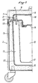
- FIG. 1 a diametrical section of a cylindrical container according to one embodiment of the invention, the closing device, elastic of preferably, of the container not being shown, and, in Figure 2, a partial section of another preferred embodiment.
- the cover 1 of the container includes an enclosure 2 for housing the thermal source and an opening, which hermetically closes by means of a plug 3 and which is located in the lower wall 4 of the cover 1.
- This cover 1 also has thermal insulation 5.
- the heat exchanger consists of metal rods 6 fixed to the bottom wall 4 of the cover 1 and which enter the enclosure 2. These rods 6 are diametrically opposite two by two.
- the tank 7 has an insulation 8 which constitutes its frame. It is divided, by a partition 9, into a main enclosure 10 receiving the graft and a peripheral enclosure 11, an annular insulating plate 12 being arranged at the upper part of the peripheral enclosure 11 and fixed on the insulation 8.
- This annular plate 12 has holes 13 intended to let through the metal rods 6 constituting the heat exchanger, rods which penetrate into the peripheral enclosure 11, when the cover 1 is put in place.
- This annular plate 12 allows the tank to be hermetically sealed. , while O-rings, not shown, ensure as perfect a seal as possible of the peripheral enclosure at the level of the holes 13.
- FIG. 2 represents an advantageous arrangement of the cover 1 and of the tank 7.
- the insulation of the tank 7 consists of a hollow outer casing 15 obtained in one piece, for example by a rotational molding process (rotational molding), and filled with an expanded polyurethane foam.
- the insulation of the cover 1 is carried out in the same way.
- the reference 16 designates the outer casing thereof, which is filled with expanded polyurethane foam.
- the peripheral enclosure 11 which delimits a main enclosure 10 receiving the graft, consists of a hollow envelope 17 obtained in one piece by rotational molding. In place, the enclosure 1 is substantially in contact with the envelope 15.
- the enclosure 11 is removable. Handles can be provided (not shown), coming from molding for example, to facilitate removal and installation.
- the enclosure 2 for housing the thermal source is also made removably. It is made in two parts, a molded envelope 18 and a closure means 19.
- the molded envelope 18 is provided with a lateral projection 20 which is intended to come into engagement with a complementary recess 21 formed in the envelope 16, for holding the enclosure 2 in place in the cover.
- the heat exchange device is identical to that of FIG. 1. Its mounting also requires a drilling operation on the wall of the peripheral enclosure 11. In addition to the passage of the metal parts 6 for the heat exchange, the holes obtained by drilling are used to fill said enclosure 11 with chilled water.
- the sealing of the peripheral enclosure 11 is simpler to ensure than in the previous embodiment, since it suffices to use appropriate O-rings (not shown).
- the container is advantageously closed by an elastic device 22, of the spring type.
- the metal parts for the heat exchange can be constituted either by simple metal studs, or by hollow metallic studs comprising a certain volume of a gas in the liquid state, such but butane.
- the studs each have a filling valve and a valve.
- the container according to the invention is advantageously provided with external handles, both on the tank and on the cover, as well as lashing means, all coming from molding, for example, so as to facilitate handling and transportation.
Abstract
L'invention concerne un conteneur isotherme pour le transport de greffons à une température constante égale à +4°C. Pour ce faire, le conteneur conforme à l'invention présente un échangeur thermique (6) réalisant un flux thermique entre une source thermique constituée notamment de glace et d'eau à 0°C environ et logée de préférence dans le couvercle (1) du conteneur et un volume tel qu'une enceinte périphérique (11).The invention relates to an insulated container for transporting grafts at a constant temperature equal to +4°C. To do this, the container according to the invention has a heat exchanger (6) producing a heat flow between a heat source consisting in particular of ice and water at approximately 0° C. and preferably housed in the lid (1) of the container and a volume such as a peripheral enclosure (11).
Description
La présente invention a trait à un conteneur isotherme, destiné notamment au transport de greffons, en particulier coeur ou ensemble coeur-poumons, à une température constante égale à +4°C.The present invention relates to an insulated container, intended in particular for the transport of grafts, in particular the heart or whole heart-lungs, at a constant temperature equal to + 4 ° C.
Le développement récent des greffes d'organes a fait apparaître le besoin d'un dispositif permettant le transport d'un organe à transplanter, de l'hôpital du donneur à celui du receveur et cela dans les conditions requises.The recent development of organ transplants has revealed the need for a device allowing the transport of an organ to be transplanted, from the donor's hospital to that of the recipient and this under the required conditions.
Les conditions à respecter impérativement sont une température constante égale à +4°C et une asepsie totale, étant entendu que le greffon doit être conservé dans du sérum physiologique.The imperative conditions are a constant temperature equal to + 4 ° C and a total asepsis, it being understood that the graft must be stored in physiological saline.
La question de l'asepsie a été résolue notamment par l'utilisation d'un triple emballage mettant en oeuvre des sacs en matière plastique, l'un, rigoureusement stérile, au contact du greffon, le second en guise de sécurité supplémentaire, le troisième, externe, autorisant la manipulation du greffon.The question of asepsis has been resolved in particular by the use of a triple packaging using plastic bags, one, strictly sterile, in contact with the graft, the second as additional safety, the third , external, authorizing manipulation of the graft.
Par contre, le problème de l'imposition et du maintien de la température à +4°C n'a pas, jusqu'ici, trouvé de solution satisfaisante. Le transport s'effectue actuellement dans des conteneurs du type glacière de camping dans lesquels on introduit de la glace en quantité suffisante, en fonction de la température extérieure et de la durée du transport. Il apparaît donc clairement qu'il ne s'agit pas d'une véritable régulation de température avec tous les problèmes que cela peut engendrer.On the other hand, the problem of imposing and maintaining the temperature at + 4 ° C has so far not found a satisfactory solution. Transport is currently carried out in containers of the camping cooler type into which sufficient ice is introduced, depending on the outside temperature and the duration of the transport. It is therefore clear that this is not a real temperature regulation with all the problems that it can cause.
Il faut bien comprendre que la résolution de ce problème ne pouvait se concevoir avec une augmentation importante de poids et d'encombrement et un apport d'énergie extérieur, la facilité de transport étant une condition importante.It should be understood that the resolution of this problem could not be conceived with a significant increase in weight and size and an external energy supply, ease of transport being an important condition.
La présente invention vise à résoudre ce problème, en proposant un conteneur permettant, sans supplément d'encombrement par rapport aux conteneurs de l'art antérieur, une mise à +4°C puis une autorégulation à +4°C pour une durée suffisante prédéterminée et qui soit d'un poids raisonnable et d'un coût de fabrication peu élevé.The present invention aims to solve this problem, by proposing a container allowing, without additional bulk compared to the containers of the prior art, a setting at + 4 ° C then a self-regulation at + 4 ° C for a sufficient predetermined duration. and which is of reasonable weight and low manufacturing cost.
Un autre objectif de l'invention est de fournir un conteneur de transport de greffons à +4°C, qui soit simple, robuste et dont le fonctionnement soit indéréglable.Another objective of the invention is to provide a container for transporting grafts at + 4 ° C., which is simple, robust and whose operation is foolproof.
Un autre objectif encore de l'invention est de fournir un conteneur de transport de greffons à +4°C dont l'autonomie est au moins de 10 heures dans des conditions de température extérieure normales.Yet another objective of the invention is to provide a container for transporting grafts at + 4 ° C. whose autonomy is at least 10 hours under normal outside temperature conditions.
L'invention a pour objet un conteneur formé d'une cuve et d'un couvercle isolés thermiquement du milieu extérieur, destiné au transport de greffons à +4°C, caractérisé par un échangeur thermique situé à la partie supérieure du conteneur, de préférence à la partie inférieure du couvercle, et un volume périphérique rempli d'eau, tel que chemise d'eau ou enceinte périphérique, ledit échangeur assurant un transfert thermique entre une source thermique susjacente à température constante et la couche d'eau située à la partie supérieure dudit volume.The subject of the invention is a container formed by a tank and a cover thermally insulated from the outside environment, intended for the transport of grafts at + 4 ° C., characterized by a heat exchanger situated at the top of the container, preferably at the bottom of the lid, and a peripheral volume filled of water, such as a water jacket or peripheral enclosure, said exchanger ensuring a heat transfer between an overlying thermal source at constant temperature and the layer of water located at the top of said volume.
La source thermique est, par exemple, une source de froid constituée notamment d'eau et de glace au voisinage de 0°C. Dans le cas d'une température externe supérieure à +4°C, il se produit des échanges thermiques entre l'intérieur du conteneur et le milieu extérieur. L'eau qui se réchauffe au-dessus de +4°C monte à la partie supérieure de la cuve, en raison de sa densité moindre par rapport à celle de l'eau à +4°C. Il s'établit donc un flux thermique, dirigé vers la source de froid, et il s'ensuit un refroidissement, essentiellement par conduction, de cette couche d'eau supérieure qui, en atteignant +4°C, laissera sa place, s'il y a lieu, à de l'eau plus chaude. En d'autres termes, on obtient une certaine stratification de l'eau dans la cuve, la plus grande partie de la cuve étant à +4°C et la couche d'eau supérieure présentant une température tendant à se rapprocher de +4°C. Le greffon reste donc toujours en contact ou au voisinage de l'eau à +4°C.The thermal source is, for example, a cold source consisting in particular of water and ice in the vicinity of 0 ° C. In the case of an external temperature greater than + 4 ° C, heat exchanges occur between the interior of the container and the external environment. Water that heats up above + 4 ° C rises to the top of the tank, due to its lower density compared to that of water at + 4 ° C. It therefore establishes a heat flow, directed towards the cold source, and there follows a cooling, essentially by conduction, of this upper layer of water which, reaching + 4 ° C, will leave its place, s' if applicable, to hotter water. In other words, a certain stratification of the water in the tank is obtained, the greater part of the tank being at + 4 ° C. and the upper layer of water having a temperature tending to approach + 4 ° vs. The graft therefore always remains in contact with or near water at + 4 ° C.
Si de l'eau de la cuve se refroidit en dessous de +4°C, cette eau monte ou reste dans la partie supérieure de la cuve, en raison d'une densité moindre par rapport à celle de l'eau à +4°C. Le gradient de température étant très faible, le flux thermique diminue et l'échange thermique se bloque et, en raison de la quasi-absence de convection et de la faiblesse de la conduction, on aboutit à un maintien temporaire de la situation.If the water in the tank cools below + 4 ° C, this water rises or remains in the upper part of the tank, due to a lower density compared to that of water at + 4 ° vs. The temperature gradient is very low, the heat flow decreases and the heat exchange is blocked and, due to the virtual absence of convection and the weak conduction, this results in a temporary maintenance of the situation.
Lorsque la température externe est en permanence inférieure à +4°C, il peut être utile de remplacer la source de froid par une source de chaleur.When the external temperature is permanently below + 4 ° C, it may be useful to replace the cold source with a heat source.
Dans tous les cas, les variations de température se localisent au niveau de l'échangeur thermique et sont donc sans effet sur le greffon, à condition, bien sûr, que la source thermique ne soit pas épuisée.In all cases, the temperature variations are localized at the level of the heat exchanger and therefore have no effect on the graft, provided, well sure that the heat source is not exhausted.
De préférence, le conteneur selon l'invention se caractérise par le fait que son couvercle comporte une enceinte pour loger la source thermique et une ouverture, qui se ferme hermétiquement, pour l'introduction de la source thermique.Preferably, the container according to the invention is characterized in that its cover comprises an enclosure for housing the thermal source and an opening, which closes hermetically, for the introduction of the thermal source.
De préférence, l'échangeur thermique est constitué par des pièces réalisées en métal bon conducteur thermique, fixées au couvercle et agencées de façon à pénétrer dans l'enceinte contenant la source thermique et à dépasser du couvercle dans le sens opposé pour pénétrer dans la partie supérieure de la chemise d'eau ou enceinte périphérique. Le nombre et les caractéristiques de ces pièces métalliques dépendront, bien entendu, des dimensions du conteneur et des échanges thermiques avec le milieu extérieur. Pourtant, l'invention a l'avantage de ne pas être trop sensible à la précision apportée dans le choix des dimensions de ces pièces métalliques. On pourra prendre le soin de prévoir ces dimensions en fonction des conditions extrêmes de température susceptibles d'être rencontrées, en particulier les températures les plus élevées.Preferably, the heat exchanger consists of parts made of metal which is a good thermal conductor, fixed to the cover and arranged so as to penetrate into the enclosure containing the thermal source and to protrude from the cover in the opposite direction to enter the part. top of the water jacket or peripheral enclosure. The number and characteristics of these metal parts will depend, of course, on the dimensions of the container and the heat exchanges with the external environment. However, the invention has the advantage of not being too sensitive to the precision provided in the choice of dimensions of these metal parts. Care may be taken to provide these dimensions as a function of the extreme temperature conditions likely to be encountered, in particular the highest temperatures.
Dans un mode de réalisation particulier de l'invention, les pièces pour l'échange thermique sont des tétons métalliques creux destinés à recevoir un certain volume de gaz à l'état liquide, ledit gaz, à l'état gazeux, étant condensable aux environs de 0°C. Les tétons sont munis d'une valve de remplissage et d'une soupape à la manière, par exemple, des briquets.In a particular embodiment of the invention, the parts for the heat exchange are hollow metal pins intended to receive a certain volume of gas in the liquid state, said gas, in the gaseous state, being condensable in the vicinity 0 ° C. The nipples are provided with a filling valve and a valve in the manner, for example, of lighters.
Grâce à cette réalisation, les échanges thermiques sont accélérés. Le réchauffement du gaz liquide à la partie inférieure des tétons provoque une transformation de liquide en gaz, le gaz passe dans le volume libre supérieur des tétons et vient se condenser sur les parois de ceux-ci, lesquelles sont à 0°C environ.Thanks to this embodiment, the heat exchanges are accelerated. The heating of the liquid gas at the bottom of the nipples causes a transformation of liquid into gas, the gas passes into the upper free volume of the nipples and comes to condense on the walls of these, which are at around 0 ° C.
Le gaz employé peut être avantageusement du butane.The gas used can advantageously be butane.
De préférence, les pièces métalliques formant l'échangeur thermique sont réalisées dand un alliage d'aluminium/magnésium (AG3 ou AG5) insensible aux chlorures pour permettre une désinfection périodique par eau de Javel.Preferably, the metal parts forming the heat exchanger are made of an aluminum / magnesium alloy (AG3 or AG5) insensitive to chlorides to allow periodic disinfection with bleach.
Dans un mode de réalisation, la cuve du conteneur est divisée, par une cloison, en une enceinte principale recevant le greffon et éventuellement de l'eau entre 0°C et +4°C et une enceinte périphérique ouverte à sa partie supérieure de manière que les pièces métalliques réalisant l'échangeur thermique puissent y pénétrer lors de la mise en place du couvercle.In one embodiment, the container tank is divided, by a partition, into a main enclosure receiving the graft and possibly water between 0 ° C and + 4 ° C and a peripheral enclosure open at its upper part so that the metal parts making the heat exchanger can enter it when the cover is fitted.
La cloison de séparation des duex enceintes est de préférence constituée en matière plastique.The partition dividing the two enclosures is preferably made of plastic.
Dans un autre mode de réalisation avantageux, l'enceinte pour loger la source thermique et l'enceinte périphérique sont amovibles par rapport à des parois isolantes formant respectivement le couvercle et la cuve.In another advantageous embodiment, the enclosure for housing the thermal source and the peripheral enclosure are removable with respect to insulating walls respectively forming the cover and the tank.
Dans les deux cas, les variations de température dues aux échanges thermiques avec le milieu extérieur, seront confinées au niveau de l'enceinte périphérique. L'enceinte principale sera pratiquement indemne de variations thermiques.In both cases, the temperature variations due to heat exchanges with the external environment will be confined to the level of the peripheral enclosure. The main enclosure will be practically free from thermal variations.
Afin de minimiser au maximum la convection tout en respectant une isolation suffisante de l'enceinte principale, l'épaisseur de l'enceinte périphérique est choisie relativement étroite, de préférence environ 40 mm.In order to minimize convection as much as possible while respecting sufficient insulation of the main enclosure, the thickness of the peripheral enclosure is chosen to be relatively narrow, preferably around 40 mm.
Dans ces modes de réalisation, lors de la mise en place d'un greffon dans l'enceinte principale, l'enceinte périphérique est, par exemple, remplie d'eau entre +1°C et +4°C. En variante, il est possible de remplir l'enceinte périphérique avec une eau à une température qui prenne en compte la température interne du greffon en question. Connaissant le volume exact de l'enceinte périphérique et la chaleur spécifique du greffon, on amène la température de l'eau destinée à l'enceinte périphérique à une valeur telle, que le flux thermique nécessaire à amener le greffon à +4°C est grandement compensé, sans que l'échangeur thermique ait beaucoup à intervenir. Une économie de temps et de source de froid en résulte.In these embodiments, when a graft is placed in the main enclosure, the peripheral enclosure is, for example, filled with water between + 1 ° C and + 4 ° C. As a variant, it is possible to fill the peripheral enclosure with water at a temperature which takes into account the internal temperature of the graft in question. Knowing the exact volume of the peripheral enclosure and the specific heat of the graft, we bring the temperature of the water intended for the peripheral enclosure at a value such that the heat flow necessary to bring the graft to + 4 ° C. is greatly compensated for, without the heat exchanger having much to do. This saves time and the source of cold.
La source thermique, de préférence un mélange d'eau et de glace, qui est avantageusement logée dans le couvercle, et qui est en rapport avec l'extrémité supérieure de l'échangeur, peut avoir toute forme géométrique. Elle peut être isolée thermiquement ou non de la cuve. Cependant, de préférence, la source s'étend sensiblement, au-dessus de la cuve, sur sensiblement toute la largeur de la cuve, le logement de la source ayant un fond plat, de sorte que la partie la plus dense de l'eau du mélange eau/glace de la source reposera sur ce fond dont la température tendra vers +4°C, complétant ainsi l'enceinte périphérique d'eau à +4°C.The thermal source, preferably a mixture of water and ice, which is advantageously housed in the cover, and which is in relation to the upper end of the exchanger, can have any geometric shape. It can be thermally isolated or not from the tank. Preferably, however, the source extends substantially, above the tank, over substantially the entire width of the tank, the housing of the source having a flat bottom, so that the densest part of the water of the water / ice mixture from the source will rest on this bottom, the temperature of which will tend to + 4 ° C, thus completing the peripheral enclosure of water at + 4 ° C.
On préférera que les conducteurs thermiques de l'échangeur, par exemple des tiges métalliques, pénètrent, vers le haut, sur une certaine distance au-dessus du fond de la source, afin d'être au contact de la partie la plus froide de la source.It will be preferred that the heat conductors of the exchanger, for example metal rods, penetrate, upwards, a certain distance above the bottom of the source, in order to be in contact with the coldest part of the source.
Le conteneur selon l'invention est de préférence cylindrique.The container according to the invention is preferably cylindrical.
Pour le transport de coeur à greffer, le conteneur présente, de préférence, un diamètre externe de l'ordre de 390 mm pour une hauteur hors-tout de l'ordre de 470 mm.For the transport of heart to be grafted, the container preferably has an external diameter of the order of 390 mm for an overall height of the order of 470 mm.
Pour le transport d'un ensemble coeur-poumons, le conteneur présente, de préférence, un diamètre externe de l'ordre de 480 mm pour une hauteur hors-tout de l'ordre de 540 mm. L'épaisseur de l'enceinte périphérique est de l'ordre de 40 mm, en ce qui concerne la partie périphérique latérale, et de l'ordre de 50 mm, en ce qui concerne le fond. Le calorifugeage a une épaisseur de l'ordre de 50 à 75 mm. Les tiges métalliques réalisant l'échangeur thermique sont au nombre de 6 et présentent un diamètre de 20 mm pour une longueur de 80 mm.For the transport of a heart-lung assembly, the container preferably has an external diameter of the order of 480 mm for an overall height of the order of 540 mm. The thickness of the peripheral enclosure is of the order of 40 mm, as regards the lateral peripheral part, and of the order of 50 mm, as regards the bottom. The insulation has a thickness of the order of 50 to 75 mm. The metal rods making the heat exchanger are 6 in number and have a diameter of 20 mm for a length of 80 mm.
L'invention va être maintenant décrite plus en détail à l'aide du dessin annexé qui présente, à la figure 1, une coupe diamétrale d'un conteneur cylindrique selon un mode de réalisation de l'invention, le dispositif de fermeture, élastique de préférence, du conteneur n'étant pas représenté, et, à la figure 2, une coupe partielle d'un autre mode de réalisation préféré.The invention will now be described in more detail with the aid of the appended drawing which shows, in FIG. 1, a diametrical section of a cylindrical container according to one embodiment of the invention, the closing device, elastic of preferably, of the container not being shown, and, in Figure 2, a partial section of another preferred embodiment.
Si l'on se reporte à la figure 1, le couvercle 1 du conteneur comporte une enceinte 2 pour loger la source thermique et une ouverture, qui se ferme hermétiquement au moyen d'un bouchon 3 et qui est située dans la paroi inférieure 4 du couvercle 1. Ce couvercle 1 présente également un calorifugeage 5.Referring to FIG. 1, the
Selon la figure 1, l'échangeur thermique est constitué par des tiges métalliques 6 fixées à la paroi inférieure 4 du couvercle 1 et qui pénètrent dans l'enceinte 2. Ces tiges 6 sont opposées diamétralement deux à deux.According to Figure 1, the heat exchanger consists of
La cuve 7 présente un calorifugeage 8 qui en constitue l'armature. Elle est divisée, par une cloison 9, en une enceinte principale 10 recevant le greffon et une enceinte périphérique 11, une plaque annulaire 12 isolante étant agencée à la partie supérieure de l'enceinte périphérique 11 et fixée sur le calorifugeage 8. Cette plaque annulaire 12 présente des trous 13 destinés à laisser passer les tiges métalliques 6 constituant l'échangeur thermique, tiges qui pénètrent dans l'enceinte périphérique 11, lors de la mise en place du couvercle 1. Cette plaque annulaire 12 permet la fermeture hermétique de la cuve, tandis que des joints toriques non représentés assurent une étanchéité aussi parfaite que possible de l'enceinte périphérique au niveau des trous 13.The tank 7 has an
On se réfère maintenant à la figure 2 qui représente un agencement avantageux du couvercle 1 et de la cuve 7.Reference is now made to FIG. 2 which represents an advantageous arrangement of the
Le calorifugeage de la cuve 7 est constitué d'une enveloppe extérieure creuse 15 obtenue d'un seul tenant, par exemple par un procédé de moulage par rotation (rotomoulage), et remplie d'une mousse de polyuréthane expansée.The insulation of the tank 7 consists of a hollow
Le calorifugeage du couvercle 1 est réalisé de la même manière. Le repère 16 désigne l'enveloppe extérieure de celui-ci, laquelle est remplie de mousse de polyuréthane expansée.The insulation of the
L'enceinte périphérique 11, qui délimite une enceinte principale 10 recevant le greffon, est constituée d'une enveloppe creuse 17 obtenue d'une seule pièce par rotomoulage. En place, l'enceinte 1 est sensiblement au contact de l'enveloppe 15. L'enceinte 11 est amovible. On peut prévoir des poignées (non représentées), venant de moulage par exemple, pour en faciliter le retrait et la mise en place.The
L'enceinte 2 pour loger la source thermique est réalisée aussi de façon amovible. Elle est réalisée en deux pièces, une enveloppe moulée 18 et un moyen de fermeture 19. L'enveloppe moulée 18 est munie d'une saillie latérale 20 qui est destinée à venir en prise avec un renfoncement complémentaire 21 ménagé dans l'enveloppe 16, pour le maintien en place de l'enceinte 2 dans le couvercle.The
Le dispositif d'échange de chaleur est identique à celui de la figure 1. Son montage nécessite en plus une opération de perçage de la paroi de l'enceinte périphérique 11. Outre le passage des pièces métalliques 6 pour l'échange de chaleur, les trous obtenus par perçage servent au remplissage de ladite enceinte 11 avec de l'eau réfrigérée.The heat exchange device is identical to that of FIG. 1. Its mounting also requires a drilling operation on the wall of the
L'étanchéité de l'enceinte périphérique 11 est plus simple à assurer que dans le mode de réalisation précédent, puisqu'il suffit d'utiliser des joints toriques appropriés (non représentés).The sealing of the
En cas de besoin, on peut parfaire l'étanchéité de l'ensemble par l'emploi d'un moyen d'étanchéité périphérique.If necessary, we can perfect sealing of the assembly by the use of a peripheral sealing means.
Enfin, la fermeture du conteneur est avantageusement assurée par un dispositif élastique 22, du type à ressort.Finally, the container is advantageously closed by an
Dans ces deux modes de réalisation décrits, on comprend que les pièces métalliques pour l'échange thermique peuvent être constituées soit par des tenons métalliques simples, soit par des tenons métalliques creux comportant un certain volume d'un gaz à l'état liquide, tel que du butane. Dans ce dernier cas, les tenons comportent chacun une valve de remplissage et une soupape.In these two embodiments described, it is understood that the metal parts for the heat exchange can be constituted either by simple metal studs, or by hollow metallic studs comprising a certain volume of a gas in the liquid state, such but butane. In the latter case, the studs each have a filling valve and a valve.
En outre, le conteneur selon l'invention est avantageusement muni de poignées extérieures, aussi bien sur la cuve que sur le couvercle, ainsi que de moyens d'arrimage, venant tous de moulage, par exemple, de façon à en faciliter la manipulation et le transport.In addition, the container according to the invention is advantageously provided with external handles, both on the tank and on the cover, as well as lashing means, all coming from molding, for example, so as to facilitate handling and transportation.
Il est bien entendu que l'invention n'est nullement limitée à ce qui a été décrit et qu'on peut lui apporter diverses modifications de forme ou de matériau sans pour cela s'éloigner ni de son cadre ni de son esprit.It is understood that the invention is in no way limited to what has been described and that it can make various modifications of shape or material without thereby departing from either its setting or its spirit.
Claims (13)
Applications Claiming Priority (2)
| Application Number | Priority Date | Filing Date | Title |
|---|---|---|---|
| FR8802845 | 1988-03-07 | ||
| FR8802845A FR2628077B1 (en) | 1988-03-07 | 1988-03-07 | CONTAINER FOR TRANSPORTING GRAFT |
Publications (2)
| Publication Number | Publication Date |
|---|---|
| EP0336791A1 true EP0336791A1 (en) | 1989-10-11 |
| EP0336791B1 EP0336791B1 (en) | 1992-12-23 |
Family
ID=9363957
Family Applications (1)
| Application Number | Title | Priority Date | Filing Date |
|---|---|---|---|
| EP89400618A Expired - Lifetime EP0336791B1 (en) | 1988-03-07 | 1989-03-06 | Container for the transport of transplants |
Country Status (4)
| Country | Link |
|---|---|
| US (1) | US4958506A (en) |
| EP (1) | EP0336791B1 (en) |
| DE (1) | DE68903985T2 (en) |
| FR (1) | FR2628077B1 (en) |
Cited By (4)
| Publication number | Priority date | Publication date | Assignee | Title |
|---|---|---|---|---|
| WO1991015970A1 (en) * | 1990-04-20 | 1991-10-31 | Zelsa Patentverwertungs Ges M | Process and device for storing foodstuffs, plants, meat and other organic substances |
| FR2667297A1 (en) * | 1990-09-28 | 1992-04-03 | Electrolux Sarl | MEDICAL CONTAINER AIR CONDITIONER. |
| EP0586088A2 (en) * | 1992-09-04 | 1994-03-09 | Vari-Lite, Inc. | Storage and transportation trunk for lighting equipment |
| CN105857933A (en) * | 2016-05-16 | 2016-08-17 | 中国人民解放军总医院第附属医院 | Medicine storage device |
Families Citing this family (39)
| Publication number | Priority date | Publication date | Assignee | Title |
|---|---|---|---|---|
| US5105627A (en) * | 1990-04-20 | 1992-04-21 | Nihon Freezer Co., Ltd. | Cryopreservation container of animal cell |
| US5103651A (en) * | 1990-08-31 | 1992-04-14 | Instacool Inc Of North America | Plasma storage freezer and thermal transport device |
| US5355684A (en) * | 1992-04-30 | 1994-10-18 | Guice Walter L | Cryogenic shipment or storage system for biological materials |
| US5417082A (en) * | 1992-07-09 | 1995-05-23 | Utd Incorporated | Constant temperature container |
| US5236088A (en) * | 1992-07-29 | 1993-08-17 | Smith & Nephew Richards, Inc. | Biomedical material shipment kit and method |
| US5291746A (en) * | 1993-03-10 | 1994-03-08 | Abbott Derwood C | Container for storage, collection and transportation of medical waste |
| US5419152A (en) * | 1993-12-13 | 1995-05-30 | In Vitro Technologies, Inc. | Apparatus for packaging temperature sensitive materials for transportation |
| US5586438A (en) * | 1995-03-27 | 1996-12-24 | Organ, Inc. | Portable device for preserving organs by static storage or perfusion |
| US6028293A (en) * | 1998-04-20 | 2000-02-22 | Tcp Reliable Inc. | Temperature-controlled container with heating means |
| US6020575A (en) * | 1998-04-20 | 2000-02-01 | Tcp/Reliable Inc. | Temperature-controlled container with heating means and eutectic pack |
| US6977140B1 (en) * | 1998-09-29 | 2005-12-20 | Organ Recovery Systems, Inc. | Method for maintaining and/or restoring viability of organs |
| US6673594B1 (en) | 1998-09-29 | 2004-01-06 | Organ Recovery Systems | Apparatus and method for maintaining and/or restoring viability of organs |
| US7749693B2 (en) * | 1998-09-29 | 2010-07-06 | Lifeline Scientific, Inc. | Method of determining that an organ is not suitable for transplantation and using it for testing substances |
| US7043935B2 (en) * | 2000-07-03 | 2006-05-16 | Hunter Rick C | Enclosure thermal shield |
| EP1299679B1 (en) * | 2000-07-03 | 2007-02-07 | Rick C. Hunter | Enclosure thermal shield |
| US6490880B1 (en) | 2000-10-26 | 2002-12-10 | Islet Technology Inc. | Regulated organ containment shipping system using dual-layer preservation liquid |
| FR2833075A1 (en) * | 2001-11-30 | 2003-06-06 | Vincent Jean Francois | REFRIGERATED TROLLEY |
| US8361091B2 (en) * | 2002-08-23 | 2013-01-29 | Organ Recovery Systems, Inc. | Cannulas, cannula mount assemblies, and clamping methods using such cannulas and cannula mount assemblies |
| US20040170950A1 (en) * | 2002-09-12 | 2004-09-02 | Prien Samuel D. | Organ preservation apparatus and methods |
| US7691622B2 (en) * | 2003-04-04 | 2010-04-06 | Lifeline Scientific, Inc. | Method and apparatus for transferring heat to or from an organ or tissue container |
| US8128740B2 (en) * | 2003-04-04 | 2012-03-06 | Organ Recovery Systems, Inc. | Device for separating gas from a liquid path |
| US20050153271A1 (en) * | 2004-01-13 | 2005-07-14 | Wenrich Marshall S. | Organ preservation apparatus and methods |
| JP4487799B2 (en) * | 2005-02-25 | 2010-06-23 | 株式会社日立製作所 | Constant temperature transport container |
| DE102006053566A1 (en) * | 2006-08-07 | 2008-02-14 | Tanya Owen | Mobile cooling box e.g. for camping, has wheels arranged its lower side and wheels rotate around appropriate vertical axes |
| US20080145919A1 (en) * | 2006-12-18 | 2008-06-19 | Franklin Thomas D | Portable organ and tissue preservation apparatus, kit and methods |
| WO2009065005A1 (en) * | 2007-11-14 | 2009-05-22 | Stratatech Corporation | Cold storage of organotypically cultured skin equivalents for clinical applications |
| US8205468B2 (en) * | 2008-05-13 | 2012-06-26 | Thermobuffer Llc | Thermodynamic container |
| GB2471865B (en) * | 2009-07-15 | 2011-06-29 | Bright Light Solar Ltd | Refrigeration apparatus |
| US8828034B2 (en) | 2011-04-29 | 2014-09-09 | Lifeline Scientific, Inc. | Cannula |
| US9642625B2 (en) | 2011-04-29 | 2017-05-09 | Lifeline Scientific, Inc. | Cannula for a donor organ with or without an aortic cuff or patch |
| US9022978B2 (en) | 2011-04-29 | 2015-05-05 | Lifeline Scientific, Inc. | Universal sealring cannula |
| GB2514502B (en) | 2012-01-27 | 2019-07-03 | The Sure Chill Company Ltd | Refrigeration apparatus |
| US9115936B2 (en) * | 2012-02-15 | 2015-08-25 | Wave Power Technology, Inc. | Cooling apparatus and method using a vacuum pump |
| GB201301494D0 (en) | 2013-01-28 | 2013-03-13 | True Energy Ltd | Refrigeration apparatus |
| WO2015011477A1 (en) * | 2013-07-23 | 2015-01-29 | The Sure Chill Company Limited | Refrigeration apparatus and method |
| GB2534910C (en) * | 2015-02-05 | 2021-10-27 | Laminar Medica Ltd | A Thermally Insulated Container and Method for Making Same |
| EP3341665A4 (en) | 2015-09-11 | 2019-05-01 | The Sure Chill Company Limited | Portable refrigeration apparatus |
| JP7285455B2 (en) * | 2019-06-17 | 2023-06-02 | パナソニックIpマネジメント株式会社 | Constant temperature container |
| US11142389B1 (en) * | 2020-11-20 | 2021-10-12 | Xiamen Kingqueen Industrial Co., Ltd. | Thermal container |
Citations (4)
| Publication number | Priority date | Publication date | Assignee | Title |
|---|---|---|---|---|
| CH375658A (en) * | 1961-08-17 | 1964-02-29 | Dagesco S A | Container for keeping goods at a determined temperature |
| US4530816A (en) * | 1983-06-15 | 1985-07-23 | Hamilton Farm | Method and device for cooling, preserving and safely transporting biological material |
| FR2581513A1 (en) * | 1983-06-14 | 1986-11-14 | Nippon Light Metal Co | DOUBLE-WALK COLD CONSERVATIVE CONTAINER |
| DE3627201A1 (en) * | 1985-08-19 | 1987-04-09 | Univ Rostock | Cooling container, especially for donor organs |
Family Cites Families (13)
| Publication number | Priority date | Publication date | Assignee | Title |
|---|---|---|---|---|
| US1571438A (en) * | 1925-04-02 | 1926-02-02 | Henry S Schopf | Provision safe |
| US1641192A (en) * | 1926-09-13 | 1927-09-06 | Louis B Olin | Iceless refrigerator tank |
| CH215203A (en) * | 1940-07-15 | 1941-06-15 | Kiene Sen Max | Cooling containers for butter, milk and other foods. |
| GB808690A (en) * | 1956-11-21 | 1959-02-11 | George Szekely | Improvements in and relating to the cooling of solid and liquid substances |
| US3195619A (en) * | 1961-12-19 | 1965-07-20 | John Edward Baker | Heat transfer method to preclude ice formation on paving |
| GB1137001A (en) * | 1965-04-09 | 1968-12-18 | Plessey Co Ltd | Improvements in or relating to housing arrangements for cooling electrical equipment |
| US3406532A (en) * | 1966-11-09 | 1968-10-22 | Aladdin Ind Inc | Food and beverage containers having integral compartments containing a freezable liquid |
| US3564727A (en) * | 1969-03-03 | 1971-02-23 | Virtis Co Inc | Freeze dryer using an expendable refrigerant |
| CH609140A5 (en) * | 1976-05-18 | 1979-02-15 | Sulzer Ag | |
| US4240268A (en) * | 1978-10-13 | 1980-12-23 | Yuan Shao W | Ground cold storage and utilization |
| US4346569A (en) * | 1978-10-13 | 1982-08-31 | Yuan Shao W | Natural ice for cooling energy |
| US4322954A (en) * | 1979-05-23 | 1982-04-06 | Sheehan Laurence M | Portable cooler for medicine |
| US4498312A (en) * | 1983-11-23 | 1985-02-12 | Schlosser Edward P | Method and apparatus for maintaining products at selected temperatures |
-
1988
- 1988-03-07 FR FR8802845A patent/FR2628077B1/en not_active Expired - Fee Related
-
1989
- 1989-03-06 EP EP89400618A patent/EP0336791B1/en not_active Expired - Lifetime
- 1989-03-06 DE DE8989400618T patent/DE68903985T2/en not_active Expired - Fee Related
- 1989-03-06 US US07/319,294 patent/US4958506A/en not_active Expired - Fee Related
Patent Citations (4)
| Publication number | Priority date | Publication date | Assignee | Title |
|---|---|---|---|---|
| CH375658A (en) * | 1961-08-17 | 1964-02-29 | Dagesco S A | Container for keeping goods at a determined temperature |
| FR2581513A1 (en) * | 1983-06-14 | 1986-11-14 | Nippon Light Metal Co | DOUBLE-WALK COLD CONSERVATIVE CONTAINER |
| US4530816A (en) * | 1983-06-15 | 1985-07-23 | Hamilton Farm | Method and device for cooling, preserving and safely transporting biological material |
| DE3627201A1 (en) * | 1985-08-19 | 1987-04-09 | Univ Rostock | Cooling container, especially for donor organs |
Cited By (8)
| Publication number | Priority date | Publication date | Assignee | Title |
|---|---|---|---|---|
| WO1991015970A1 (en) * | 1990-04-20 | 1991-10-31 | Zelsa Patentverwertungs Ges M | Process and device for storing foodstuffs, plants, meat and other organic substances |
| US5403609A (en) * | 1990-04-20 | 1995-04-04 | Gyula Subotics | Method and equipment for storing foodstuffs, plants, vegetables, meats and other organic substances |
| FR2667297A1 (en) * | 1990-09-28 | 1992-04-03 | Electrolux Sarl | MEDICAL CONTAINER AIR CONDITIONER. |
| EP0479635A1 (en) * | 1990-09-28 | 1992-04-08 | ELECTROLUX S.à.r.l. | Air-conditioned medical container |
| US5285657A (en) * | 1990-09-28 | 1994-02-15 | Electrolux S.A.R.L. | Controlled-environment medical container |
| EP0586088A2 (en) * | 1992-09-04 | 1994-03-09 | Vari-Lite, Inc. | Storage and transportation trunk for lighting equipment |
| EP0586088A3 (en) * | 1992-09-04 | 1994-08-24 | Vari Lite Inc | Storage and transportation trunk for lighting equipment |
| CN105857933A (en) * | 2016-05-16 | 2016-08-17 | 中国人民解放军总医院第附属医院 | Medicine storage device |
Also Published As
| Publication number | Publication date |
|---|---|
| US4958506A (en) | 1990-09-25 |
| FR2628077B1 (en) | 1990-08-03 |
| DE68903985D1 (en) | 1993-02-04 |
| FR2628077A1 (en) | 1989-09-08 |
| DE68903985T2 (en) | 1993-07-22 |
| EP0336791B1 (en) | 1992-12-23 |
Similar Documents
| Publication | Publication Date | Title |
|---|---|---|
| EP0336791B1 (en) | Container for the transport of transplants | |
| FR2533304A1 (en) | REFRIGERATING APPARATUS FOR RAPID COOLING OF SPECIMENS, ESPECIALLY BIOLOGICAL | |
| FR2458484A1 (en) | METAL CONTAINER, METHOD FOR MANUFACTURING THE SAME, AND ITS APPLICATION TO THE PRODUCTION OF AN INDIRECT LIQUID HEATING DEVICE | |
| FR2912429A1 (en) | STEAM IRONING APPARATUS CONTAINING A WATER TANK IN DIRECT COMMUNICATION WITH A BOILING CHAMBER | |
| EP2103565B1 (en) | Beverage-dispensing appliance equipped with a heat-conductor element | |
| EP0471826B1 (en) | Container for transporting a material in the solid state | |
| FR2563617A1 (en) | Process and device for keeping a bottle of wine at a predetermined temperature | |
| EP0159209B1 (en) | Emergency container for an accidentally amputated limb | |
| EP0261007A1 (en) | Device for heating liquids by micro-waves, especially blood | |
| EP2204113B1 (en) | Pressure cooker with encapsulated purging thermal switch | |
| FR2524960A1 (en) | AUTONOMOUS DEVICE FOR ASSISTING A SAFETY VALVE | |
| FR2956300A1 (en) | Electrical appliance i.e. domestic yogurt maker, for heating food using vapor, has case provided with main lid that is arranged with housing to store water dispensing container of appliance | |
| EP0220086B1 (en) | Liquefied-gas transfer line comprising a thermal screen provided with a heat exchanger | |
| FR2826715A1 (en) | Heat exchanger for drinking water dispensing flexible container has base and sidewalls defining seating of thermally conductive material | |
| FR2748942A1 (en) | Fire-resistant container for liquefied gas bottle | |
| WO1986007440A1 (en) | Cooling tunnel and method | |
| BE461390A (en) | ||
| WO2023118374A1 (en) | Cryogenic fluid storage unit | |
| FR2880413A1 (en) | Heating device, useful to heat liquid, comprises container and mechanical activator | |
| FR2557074A1 (en) | Stopper for a recipient containing a liquid capable of evaporating | |
| WO2004063086A1 (en) | Heat exchanger for a supple receptacle | |
| FR2849012A1 (en) | Dispenser, especially for drinking water supplied in supple container, has weight or inflatable chamber to apply pressure to container as it is emptied | |
| FR2867264A1 (en) | AUTONOMOUS DEVICE FOR HEATING A LIQUID AND METHOD FOR HEATING A LIQUID | |
| BE823939A (en) | PROCESS FOR MANUFACTURING A PACKAGING IN EXPANDED RESIN OVERMOLDED ON ITS CONTENTS. | |
| FR2607747A1 (en) | Rotomoulding mould and device including such a mould |
Legal Events
| Date | Code | Title | Description |
|---|---|---|---|
| PUAI | Public reference made under article 153(3) epc to a published international application that has entered the european phase |
Free format text: ORIGINAL CODE: 0009012 |
|
| AK | Designated contracting states |
Kind code of ref document: A1 Designated state(s): BE CH DE ES FR GB LI |
|
| 17P | Request for examination filed |
Effective date: 19900330 |
|
| 17Q | First examination report despatched |
Effective date: 19910517 |
|
| GRAA | (expected) grant |
Free format text: ORIGINAL CODE: 0009210 |
|
| AK | Designated contracting states |
Kind code of ref document: B1 Designated state(s): BE CH DE ES FR GB LI |
|
| PG25 | Lapsed in a contracting state [announced via postgrant information from national office to epo] |
Ref country code: ES Free format text: THE PATENT HAS BEEN ANNULLED BY A DECISION OF A NATIONAL AUTHORITY Effective date: 19921223 |
|
| REF | Corresponds to: |
Ref document number: 68903985 Country of ref document: DE Date of ref document: 19930204 |
|
| PGFP | Annual fee paid to national office [announced via postgrant information from national office to epo] |
Ref country code: GB Payment date: 19930304 Year of fee payment: 5 |
|
| PG25 | Lapsed in a contracting state [announced via postgrant information from national office to epo] |
Ref country code: LI Effective date: 19930331 Ref country code: CH Effective date: 19930331 Ref country code: BE Effective date: 19930331 |
|
| GBT | Gb: translation of ep patent filed (gb section 77(6)(a)/1977) |
Effective date: 19930305 |
|
| BERE | Be: lapsed |
Owner name: WENGER ROGER LEON LUCIEN Effective date: 19930331 Owner name: GUILHEM JACQUES RENE JEAN Effective date: 19930331 |
|
| PLBE | No opposition filed within time limit |
Free format text: ORIGINAL CODE: 0009261 |
|
| STAA | Information on the status of an ep patent application or granted ep patent |
Free format text: STATUS: NO OPPOSITION FILED WITHIN TIME LIMIT |
|
| REG | Reference to a national code |
Ref country code: CH Ref legal event code: PL |
|
| 26N | No opposition filed | ||
| PGFP | Annual fee paid to national office [announced via postgrant information from national office to epo] |
Ref country code: DE Payment date: 19940304 Year of fee payment: 6 |
|
| PG25 | Lapsed in a contracting state [announced via postgrant information from national office to epo] |
Ref country code: GB Effective date: 19940306 |
|
| PGFP | Annual fee paid to national office [announced via postgrant information from national office to epo] |
Ref country code: FR Payment date: 19940323 Year of fee payment: 6 |
|
| GBPC | Gb: european patent ceased through non-payment of renewal fee |
Effective date: 19940306 |
|
| PG25 | Lapsed in a contracting state [announced via postgrant information from national office to epo] |
Ref country code: FR Free format text: LAPSE BECAUSE OF NON-PAYMENT OF DUE FEES Effective date: 19951130 |
|
| PG25 | Lapsed in a contracting state [announced via postgrant information from national office to epo] |
Ref country code: DE Effective date: 19951201 |
|
| REG | Reference to a national code |
Ref country code: FR Ref legal event code: ST |