EP0336540A2 - Printing device and ribbon cartridge - Google Patents
Printing device and ribbon cartridge Download PDFInfo
- Publication number
- EP0336540A2 EP0336540A2 EP89301648A EP89301648A EP0336540A2 EP 0336540 A2 EP0336540 A2 EP 0336540A2 EP 89301648 A EP89301648 A EP 89301648A EP 89301648 A EP89301648 A EP 89301648A EP 0336540 A2 EP0336540 A2 EP 0336540A2
- Authority
- EP
- European Patent Office
- Prior art keywords
- ribbon
- cartridge
- printing
- arcuate wall
- platen roller
- Prior art date
- Legal status (The legal status is an assumption and is not a legal conclusion. Google has not performed a legal analysis and makes no representation as to the accuracy of the status listed.)
- Withdrawn
Links
Images

Classifications
-
- B—PERFORMING OPERATIONS; TRANSPORTING
- B41—PRINTING; LINING MACHINES; TYPEWRITERS; STAMPS
- B41J—TYPEWRITERS; SELECTIVE PRINTING MECHANISMS, i.e. MECHANISMS PRINTING OTHERWISE THAN FROM A FORME; CORRECTION OF TYPOGRAPHICAL ERRORS
- B41J17/00—Mechanisms for manipulating page-width impression-transfer material, e.g. carbon paper
- B41J17/32—Detachable carriers or holders for impression-transfer material mechanism
Definitions
- the present invention relates to a device for printing information as defined in the introductory portion of claim 1 and more particularly a device for thermal printing involving transfer of ink for an information reading and writing apparatus.
- Such an apparatus is capable of converting the information which is read from an original document into digital electrical signals which, when suitably amplified, can activate the printing device for reproducing the documents.
- the object the present invention seeks is to provide a reading and writing apparatus of small dimensions and which is simple to use from the point of view of the operator and which is capable of printing information on plain paper with a high quality of print.
- the invention also relates to a cartridge as defined in claim 6.
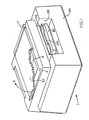
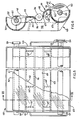
- the reading and writing machine 1 comprises a transparent exposure surface 2 on which an original document 3 to be read is positioned.
- the document 3 is covered by an original-covering mat member 5 which is hinged at 6 and which can be pivoted rearwardly as indicated by the arrow 9.
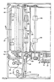
- a scanning carriage 10 ( Figures 3 and 4) is slidable below the transparent surface 2 and parallel thereto, and mounted on the scanning carriage 10 is an optical system 12 for scanning successive strips of the document 3 and converting the reflected images into electrical signals by means of photoelectric sensors 15 of the CCD type (charge coupled devices).
- CCD type charge coupled devices
- the optical system 12 is of conventional type and is formed by a double row of lamps 16 which are aligned perpendicularly to the movement of the carriage and symmetrically with respect to an array 18 of juxtaposed optical fibres.
- the optical fibres 18 constitute a short-focus lens for focusing successive strips of the images on the sensors 15 which are disposed below the lens 18.
- the carriage 10 slides on two parallel guides 22 which are fixed to the frame structure 23 and is displaced by means of a pair of belts 24, 26 which are moved by a stepping motor 20.
- the motor 20 is controlled by a control circuit, for example like that described in the present applicants' Italian patent application No 67210 A/88.
- the electrical signals generated by the sensors 15 are processed by logic circuits 32 (see Figure 3) mounted on printed circuit boards 33 which are contained in the machine 1 and which are not described in detail herein insofar as they are outside the scope of the present invention.
- the circuits 32 can be conditioned for local reproduction of the original document by means of a print head 34 or for transmission over a telephone line of the information which is read by the optical system 12 to a remote receiving location.
- the head 34 is disposed tangentially with respect to a rotatable platen roller 36 and comprises a plurality of aligned thermal elements 38 disposed in contact with the roller 36 along the generatrix thereof.
- the head 34 is capable of printing on sheets 40 of plain paper by means of an inked ribbon 42 which is interposed between the head 34 and the paper 40 and which is thus of a width which is not less than the width of the sheet 40.
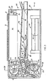
- the head 34 is mounted resiliently on a hinged cover 37 forming the rear wall of the machine 1.
- the head 34 is fixed to a frame 41 fixed to a resilient rubber block 44 which is fixed with respect to the cover 37.
- the head 34 is held in pressure contact against the roller 36 by means of springs 45 interposed between the cover 37 and the frame 41.
- the rubber block 44 permits the head 34 to adapt itself correctly to the roller 36 and at the same time isolates the head 34 from vibration generated by the printing operation.
- the cover 37 can be rotated about a pin 46 which is fixed to the frame structure 23 to give access to a space 47 housing a removable cartridge 48 containing the inked ribbon 42.
- the ribbon 42 is unwound from a supply reel 50 and is rewound onto a take-up reel 52 which is parallel to the reel 50.
- the reels 50 and 52 are mounted fixedly on two shafts 49 and 51 respectively which are rotatable on two side walls 53 and 53′ of the cartridge 48 and parallel to the axis of the platen roller 36.
- the shaft 49 is a free or idle shaft and is braked by a friction means 54 (see Figure 4) acting between a shoulder 55 on the shaft 49 and the wall 53.
- the take-up reel 52 is rotated by a gear transmission 56, 57, 58, 59 and 60 of which the gear 56 is fixed with respect to the shaft 51 and the gear 60 is fixed with respect to the platen roller 36.
- the gears 57 and 58 are mounted on the same pin 571 and interposed between them is a friction means 581 which slips to compensate for the increase in diameter of the reel 52.
- the platen roller 36 is in turn rotated by a stepping motor 62 by means of a reducing device 36.
- the cartridge 48 (see Figures 5 and 6) comprises a first cylindrical casing portion 65 which is concentric with the axis of the reel 50.
- the casing portion 65 is partially open to permit fitting and removal of the supply reel 50.
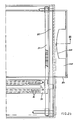
- the casing portion 65 extends between the walls 53 and 53′ and is connected over the entire length of an upper edge 66 thereof to an arcuate wall 68.
- the wall 68 is delimited by an edge 69 which is opposite and parallel to the edge 66.
- the edges 66 and 69 are straight and parallel to the axis of the reel 50.
- the wall 68 forms a cylindrical surface 70 which has its convexity directed in the opposite direction to the opening 71 of the casing portion 65. In the direction of displacement of the ribbon 42 the surface 70 is of the configuration of a circular arc with an opening angle of about 90°C (see Figure 6).
- a second casing portion 72 of the cartridge 48 which is substantially the same as the casing portion 65 extends between the walls 53 and 53′ coaxially with respect to the axis of the recovery reel 52.
- a lower edge 73 of the casing portion 72 extends in a straight line between the walls 53 and 53′ and is connected over its entire length to a substantially flat wall 75 delimited by a rounded edge 76 disposed facing the edge 69 of the wall 68.
- the distance between the edges 76 and 69 is such that, when the cartridge 48 is fitted into the space 47 (see Figure 3), the platen roller 36 is disposed between the edges 76 and 69 at a small spacing from them.
- the configuration of the surface 70 is thus disposed substantially tangentially to the platen roller 36, at the edge 69, and tangentially to a radial line 70′ with respect to the casing portion 65 at the edge 66.
- the walls 68 and 75 are stiffened by ribs 68′ and 75′ respectively, which are disposed between the above-mentioned walls and the corresponding casing portions, perpendicularly to the edges 69 and 76.
- the cartridge 48 is fitted within the space 47 by inserting the ends of the shafts 49 and 51 onto arms 78 which are fixed with respect to the structure of the machine 1.
- the inked ribbon 42 is unwound from the reel 50 (see Figure 2) and moves with its back bearing against the convex wall 68, assuming a curvature in an anticlockwise direction.
- the ribbon 42 is then wound around the platen roller 36 over an angle ⁇ of about 180°, with a curvature which is opposite to that referred to above.
- the ribbon 42 is separated from the roller 36 at the edge 76 and is then wound onto the reel 52.
- the ribbon 42 remains clinging to the surface 70 over an arc ⁇ with an average opening angle of about 55° whereby any undulations or curling which have possibly formed in the ribbon which is rolled on the reel 50 are nullified due to the combined effect of the curvature of the wall 68 and the tension created by the friction means 54.
- the best results in regard to stretching the ribbon 42 are achieved when the ribbon adheres to the surface 70 over an arc of a magnitude which is between about 50% and 80% of the magnitude of the arc ⁇ over which the ribbon 42 is wound around the platen roller 36.
- the ribbon 42 is perfectly taut.
- the sheets 40 of normal paper on which the printing operation is to be effected are collected in a cassette 80 (see Figures 1 and 3) which can be fitted into the interior of the machine 1 by way of an opening 82 in the front wall 83, at the right in Figure 3.
- a separator roller 84 After a sheet has been separated by a separator roller 84, it is transported by a feed roller 86 along a passage 87 towards the platen roller 36.
- the separator roller 84 is rotated by its own electric motor 85 (see Figure 2) and the feed roller 86 is in turn rotated by its own electric motor 88.
- the sheet 40 is pushed between the roller 36 and the inked ribbon 42, at a position corresponding to the edge 69 of the cartridge 48.
- the sheet 40 is thus entrained around the roller 36 under the ribbon 42 and in contact with the layer of ink. Therefore when the sheet 40 passes in front of the print head 34, the thermal elements 38, heating the back of the ribbon 42, transports the thermal ink of the ribbon 42 onto the sheet of paper in the form of dots.
- the ribbon 42 adheres perfectly to the sheet 40 as a result of the stretching action produced by the curved wall 68 and thus ensures a high quality of printing and perfect sliding movement of the ribbon 42 under the head 34.
- the passage 90 is substantially parallel to the passage 87 and guides the sheet 40 between a counter-roller 91 and the roller 86 to be transported onto a collecting tray 93.
- the tray 93 is formed by a fixed wall 94 and the upward outside surface 95 of a pivotable cover 96 which is hinged at points 98 on the sides of the cassette 80.
- the cover 96 projects from the profile of the machine 1 by way of a wall 102 (see also Figure 2b) which is inclined upwardly and which has a recess 103 in the central portion to permit the deposited sheets 40 to be removed easily.
Abstract
In a machine for reading and writing information, a scanning reading device (10) converts the information on a document on a bed (2) into digital electrical signals. Those signals are passed to a device for printing on plain paper for locally reproducing the original document and/or passed over a telephone cable to transmit the information to a remote receiving station. The printing device comprises a thermal printer (34) and a replaceable cartridge (48) obtaining a reel (50) for feeding the ribbon (42) which is covered with thermally transferable ink. The ribbon is as wide as a sheet of normal paper and is disposed in superposed relationship therewith on a rotatable platen roller (38) for printing information by means of a thermal print head (34). To ensure a high level of quality and uniformity of printing, the inked ribbon must be disposed in perfectly superposed relationship and without wrinkles on the sheet of paper to be printed. That is achieved by means of a curved wall (70) of the cartridge, which extends over the entire width of the inked ribbon. The wall holds the ribbon (42) in a taut condition, eliminating any wrinkles and folds which may be present in the supply reel (50).
Description
- The present invention relates to a device for printing information as defined in the introductory portion of
claim 1 and more particularly a device for thermal printing involving transfer of ink for an information reading and writing apparatus. Such an apparatus is capable of converting the information which is read from an original document into digital electrical signals which, when suitably amplified, can activate the printing device for reproducing the documents. - Various types of machines of the above-indicated type are known, in which the items of information are printed by a thermal printer on sheets of treated thermal paper. The paper is coated with a substance which is sensitive to heat and which changes in colour if it is heated. However the quality of printing produced by the treated paper is rather poor so that such machines are not suitable for reproducing original documents with a high quality of print.
- The object the present invention seeks is to provide a reading and writing apparatus of small dimensions and which is simple to use from the point of view of the operator and which is capable of printing information on plain paper with a high quality of print.
- This object is met by the printing device defined in
claim 1. - The invention also relates to a cartridge as defined in claim 6.
- The invention will be described in more detail, by way of example, with reference to the accompanying drawings, in which:
- Figure 1 is a perspective view of a reading and writing machine including a printing device according to the invention,
- Figure 2 is a partly sectional plan view of the machine shown in Figure 1,
- Figure 3 is a view in longitudinal section taken along line III-III in Figure 2,
- Figure 4 is a view in vertical section taken along line IV-IV in Figure 3,
- Figure 5 is an outside view of a cartridge for the inked ribbon of the printing device, and
- Figure 6 is a view in cross-section of the cartridge shown in Figure 1 taken along line VI-VI.
- Referring to Figure 1, the reading and
writing machine 1 comprises atransparent exposure surface 2 on which anoriginal document 3 to be read is positioned. Thedocument 3 is covered by an original-covering mat member 5 which is hinged at 6 and which can be pivoted rearwardly as indicated by thearrow 9. - A scanning carriage 10 (Figures 3 and 4) is slidable below the
transparent surface 2 and parallel thereto, and mounted on thescanning carriage 10 is anoptical system 12 for scanning successive strips of thedocument 3 and converting the reflected images into electrical signals by means ofphotoelectric sensors 15 of the CCD type (charge coupled devices). - The
optical system 12 is of conventional type and is formed by a double row oflamps 16 which are aligned perpendicularly to the movement of the carriage and symmetrically with respect to anarray 18 of juxtaposed optical fibres. Theoptical fibres 18 constitute a short-focus lens for focusing successive strips of the images on thesensors 15 which are disposed below thelens 18. - The
carriage 10 slides on twoparallel guides 22 which are fixed to theframe structure 23 and is displaced by means of a pair ofbelts stepping motor 20. - The
motor 20 is controlled by a control circuit, for example like that described in the present applicants' Italian patent application No 67210 A/88. The electrical signals generated by thesensors 15 are processed by logic circuits 32 (see Figure 3) mounted on printedcircuit boards 33 which are contained in themachine 1 and which are not described in detail herein insofar as they are outside the scope of the present invention. - The
circuits 32 can be conditioned for local reproduction of the original document by means of a print head 34 or for transmission over a telephone line of the information which is read by theoptical system 12 to a remote receiving location. - The head 34 is disposed tangentially with respect to a
rotatable platen roller 36 and comprises a plurality of aligned thermal elements 38 disposed in contact with theroller 36 along the generatrix thereof. The head 34 is capable of printing onsheets 40 of plain paper by means of an inkedribbon 42 which is interposed between the head 34 and thepaper 40 and which is thus of a width which is not less than the width of thesheet 40. - The head 34 is mounted resiliently on a hinged
cover 37 forming the rear wall of themachine 1. The head 34 is fixed to a frame 41 fixed to aresilient rubber block 44 which is fixed with respect to thecover 37. The head 34 is held in pressure contact against theroller 36 by means ofsprings 45 interposed between thecover 37 and the frame 41. Therubber block 44 permits the head 34 to adapt itself correctly to theroller 36 and at the same time isolates the head 34 from vibration generated by the printing operation. Thecover 37 can be rotated about apin 46 which is fixed to theframe structure 23 to give access to aspace 47 housing aremovable cartridge 48 containing the inkedribbon 42. - The
ribbon 42 is unwound from asupply reel 50 and is rewound onto a take-up reel 52 which is parallel to thereel 50. Thereels shafts side walls cartridge 48 and parallel to the axis of theplaten roller 36. Theshaft 49 is a free or idle shaft and is braked by a friction means 54 (see Figure 4) acting between ashoulder 55 on theshaft 49 and thewall 53. - The take-
up reel 52 is rotated by agear transmission gear 56 is fixed with respect to theshaft 51 and thegear 60 is fixed with respect to theplaten roller 36. Thegears same pin 571 and interposed between them is a friction means 581 which slips to compensate for the increase in diameter of thereel 52. Theplaten roller 36 is in turn rotated by a steppingmotor 62 by means of a reducingdevice 36. - The cartridge 48 (see Figures 5 and 6) comprises a first
cylindrical casing portion 65 which is concentric with the axis of thereel 50. Thecasing portion 65 is partially open to permit fitting and removal of thesupply reel 50. Thecasing portion 65 extends between thewalls upper edge 66 thereof to anarcuate wall 68. Thewall 68 is delimited by anedge 69 which is opposite and parallel to theedge 66. Theedges reel 50. Thewall 68 forms acylindrical surface 70 which has its convexity directed in the opposite direction to the opening 71 of thecasing portion 65. In the direction of displacement of theribbon 42 thesurface 70 is of the configuration of a circular arc with an opening angle of about 90°C (see Figure 6). - A
second casing portion 72 of thecartridge 48 which is substantially the same as thecasing portion 65 extends between thewalls recovery reel 52. A lower edge 73 of thecasing portion 72 extends in a straight line between thewalls flat wall 75 delimited by arounded edge 76 disposed facing theedge 69 of thewall 68. - The distance between the
edges cartridge 48 is fitted into the space 47 (see Figure 3), theplaten roller 36 is disposed between theedges surface 70 is thus disposed substantially tangentially to theplaten roller 36, at theedge 69, and tangentially to aradial line 70′ with respect to thecasing portion 65 at theedge 66. Thewalls ribs 68′ and 75′ respectively, which are disposed between the above-mentioned walls and the corresponding casing portions, perpendicularly to theedges - The
cartridge 48 is fitted within thespace 47 by inserting the ends of theshafts arms 78 which are fixed with respect to the structure of themachine 1. The inkedribbon 42 is unwound from the reel 50 (see Figure 2) and moves with its back bearing against theconvex wall 68, assuming a curvature in an anticlockwise direction. Theribbon 42 is then wound around theplaten roller 36 over an angle β of about 180°, with a curvature which is opposite to that referred to above. Theribbon 42 is separated from theroller 36 at theedge 76 and is then wound onto thereel 52. - The
ribbon 42 remains clinging to thesurface 70 over an arc α with an average opening angle of about 55° whereby any undulations or curling which have possibly formed in the ribbon which is rolled on thereel 50 are nullified due to the combined effect of the curvature of thewall 68 and the tension created by the friction means 54. The best results in regard to stretching theribbon 42 are achieved when the ribbon adheres to thesurface 70 over an arc of a magnitude which is between about 50% and 80% of the magnitude of the arc β over which theribbon 42 is wound around theplaten roller 36. On leaving theedge 69, theribbon 42 is perfectly taut. - The
sheets 40 of normal paper on which the printing operation is to be effected are collected in a cassette 80 (see Figures 1 and 3) which can be fitted into the interior of themachine 1 by way of anopening 82 in thefront wall 83, at the right in Figure 3. After a sheet has been separated by aseparator roller 84, it is transported by afeed roller 86 along apassage 87 towards theplaten roller 36. Theseparator roller 84 is rotated by its own electric motor 85 (see Figure 2) and thefeed roller 86 is in turn rotated by its ownelectric motor 88. Thesheet 40 is pushed between theroller 36 and the inkedribbon 42, at a position corresponding to theedge 69 of thecartridge 48. Thesheet 40 is thus entrained around theroller 36 under theribbon 42 and in contact with the layer of ink. Therefore when thesheet 40 passes in front of the print head 34, the thermal elements 38, heating the back of theribbon 42, transports the thermal ink of theribbon 42 onto the sheet of paper in the form of dots. Theribbon 42 adheres perfectly to thesheet 40 as a result of the stretching action produced by thecurved wall 68 and thus ensures a high quality of printing and perfect sliding movement of theribbon 42 under the head 34. - When the
sheet 40 is separated from theroller 36, it passes into anexit passage 90. Thepassage 90 is substantially parallel to thepassage 87 and guides thesheet 40 between acounter-roller 91 and theroller 86 to be transported onto acollecting tray 93. Thetray 93 is formed by a fixedwall 94 and the upwardoutside surface 95 of apivotable cover 96 which is hinged atpoints 98 on the sides of thecassette 80. Thecover 96 projects from the profile of themachine 1 by way of a wall 102 (see also Figure 2b) which is inclined upwardly and which has arecess 103 in the central portion to permit the depositedsheets 40 to be removed easily. - It will be appreciated that modifications, additions and/or substitution of parts may be effected in the printing device for an information reading and writing machine according to the invention without thereby departing from the scope of the invention as claimed.
Claims (8)
1. A device for printing information on plain paper which is wound around a rotatable platen roller (38), comprising a thermal print head (34) for printing the information by means of dots, line by line on the paper, and a cartridge (48) containing an inked ribbon (42) which is unwound with a preset tension from a supply reel (50) rotatable on the cartridge about an axis parallel to that of the platen roller, characterized in that the cartridge (48) comprises an arcuate wall (70) disposed between the supply reel (50) and the platen roller (38) and supporting and guiding the ribbon (42) in such a way that undulations and curling of the ribbon are eliminated under the combined effect of the curvature of the wall (70) and the tension in the ribbon.
2. A printing device according to claim 1, wherein the cartridge (48) comprises first and second casing portions (65 and 72) of substantially cylindrical shape extending between two end walls (53, 53′), the casing portions being partially open for respectively receiving the supply reel (50) and take-up reel (52), characterized in that the arcuate wall (70) is perpendicular to the end walls (53, 53′) and is connected to the first casing portion (65) along a first edge (66) parallel to the axis of the reel (50) and in that the arcuate wall (70) is delimited by a second edge (69) parallel to the first edge (66) and disposed at a small spacing from the platen roller (38).
3. A printing device according to claim 2, characterized in that the inked ribbon (42) adheres to the arcuate wall (70) over an arc (α) of a length of between 50% and 80% of the length of the arc (β) over which the ribbon is wound around the platen roller (38).
4. A printing device according to claim 2 or 3, characterized in that in the direction of movement of the ribbon (42) the arcuate wall (70) is of a profile in the form of a circular arc extending between the first and second edges (66 and 69) over about 90°.
5. A printing device according to claim 4, characterized in that the profile is substantially tangential to the platen roller (38) at the second edge (69).
6. A cartridge for an inked ribbon suitable for use in a printer for printing information by means of dots line by line on a support of plain paper, comprising first and second substantially cylindrical casing portions (65 and 72) having mutually parallel axes, the casing portions extending between two end walls (53, 53′) perpendicular to these axes and each having an opening to permit the respective insertion of a supply reel (50) and a take-up reel (52) for the ribbon (42), characterized by an arcuate wall (70) connected to the first casing portion (65) along a common edge (66) parallel to the said axes, the arcuate wall (70) extending between the end walls (53, 53′) parallel to the axes of the casing portions (65, 72), the convexity of the arcuate wall facing away from the said openings for supporting and stretching the ribbon (42) which is unwound from the supply reel (50).
7. A cartridge according to claim 6, characterized in that the arcuate wall (70) has a profile in the form of a circular arc subtending an angle of about 90°.
8. A cartridge according to claim 7, characterized in that the profile is tangential to a radial line with respect to the first cylindrical casing portion (65) in a position corresponding to the common edge (66).
Applications Claiming Priority (2)
| Application Number | Priority Date | Filing Date | Title |
|---|---|---|---|
| IT67311/88A IT1219185B (en) | 1988-04-08 | 1988-04-08 | PRINTING DEVICE FOR A READING AND WRITING MACHINE OF INFORMATION |
| IT6731188 | 1988-04-08 |
Publications (2)
| Publication Number | Publication Date |
|---|---|
| EP0336540A3 EP0336540A3 (en) | 1989-11-23 |
| EP0336540A2 true EP0336540A2 (en) | 1989-11-23 |
Family
ID=11301363
Family Applications (1)
| Application Number | Title | Priority Date | Filing Date |
|---|---|---|---|
| EP89301648A Withdrawn EP0336540A2 (en) | 1988-04-08 | 1989-02-21 | Printing device and ribbon cartridge |
Country Status (2)
| Country | Link |
|---|---|
| EP (1) | EP0336540A2 (en) |
| IT (1) | IT1219185B (en) |
Cited By (2)
| Publication number | Priority date | Publication date | Assignee | Title |
|---|---|---|---|---|
| DE4009293A1 (en) * | 1990-03-20 | 1991-09-26 | Siemens Ag | METHOD FOR LEADING A SHEET IN A RIBBON CASSETTE AND RIBBON CASSETTE FOR CARRYING OUT THE METHOD |
| US5435657A (en) * | 1993-12-28 | 1995-07-25 | Smith Corona Corporation | Label printer and tape and ink ribbon cartridge for use therein |
Citations (3)
| Publication number | Priority date | Publication date | Assignee | Title |
|---|---|---|---|---|
| JPS61154966A (en) * | 1984-12-28 | 1986-07-14 | Fujitsu Ltd | Printing medium cartridge |
| US4622563A (en) * | 1983-07-05 | 1986-11-11 | Kabushiki Kaisha Toshiba | Printing apparatus with multiple ribbon cassettes holder |
| US4687358A (en) * | 1984-05-15 | 1987-08-18 | Kabushiki Kaisha Toshiba | Transfer material holding cassette including core rotation inhibiting means |
-
1988
- 1988-04-08 IT IT67311/88A patent/IT1219185B/en active
-
1989
- 1989-02-21 EP EP89301648A patent/EP0336540A2/en not_active Withdrawn
Patent Citations (3)
| Publication number | Priority date | Publication date | Assignee | Title |
|---|---|---|---|---|
| US4622563A (en) * | 1983-07-05 | 1986-11-11 | Kabushiki Kaisha Toshiba | Printing apparatus with multiple ribbon cassettes holder |
| US4687358A (en) * | 1984-05-15 | 1987-08-18 | Kabushiki Kaisha Toshiba | Transfer material holding cassette including core rotation inhibiting means |
| JPS61154966A (en) * | 1984-12-28 | 1986-07-14 | Fujitsu Ltd | Printing medium cartridge |
Non-Patent Citations (2)
| Title |
|---|
| IBM TECHNICAL DISCLOSURE BULLETIN, vol. 27, no. 2, July 1984, pages 1337-1338, New York, US; L. FISCHER et al.: "Ribbon guide" * |
| PATENT ABSTRACTS OF JAPAN, vol. 10, no. 357 (M-540)[2414], 2nd December 1986; & JP-A-61 154 966 (FUJITSU LTD) 14-07-1986 * |
Cited By (2)
| Publication number | Priority date | Publication date | Assignee | Title |
|---|---|---|---|---|
| DE4009293A1 (en) * | 1990-03-20 | 1991-09-26 | Siemens Ag | METHOD FOR LEADING A SHEET IN A RIBBON CASSETTE AND RIBBON CASSETTE FOR CARRYING OUT THE METHOD |
| US5435657A (en) * | 1993-12-28 | 1995-07-25 | Smith Corona Corporation | Label printer and tape and ink ribbon cartridge for use therein |
Also Published As
| Publication number | Publication date |
|---|---|
| IT8867311A0 (en) | 1988-04-08 |
| EP0336540A3 (en) | 1989-11-23 |
| IT1219185B (en) | 1990-05-03 |
Similar Documents
| Publication | Publication Date | Title |
|---|---|---|
| US5128763A (en) | Ink sheet cassette and recording apparatus capable of mounting the cassette | |
| US4562444A (en) | Thermal transfer electroprinting apparatus | |
| US4910602A (en) | Thermal recorder with ink sheet cassette removably mounted in openable housing | |
| JPH06509180A (en) | photo processing equipment | |
| US4660053A (en) | Thermal transfer recording apparatus | |
| EP1336505A1 (en) | Image forming apparatus | |
| EP0326345A2 (en) | Fixing apparatus | |
| US4547783A (en) | Image forming apparatus | |
| EP0441038A2 (en) | Facsimile cartridge system | |
| EP0336540A2 (en) | Printing device and ribbon cartridge | |
| EP0677771B1 (en) | Photographic printing method and apparatus | |
| GB2152015A (en) | Sheet guide support tray | |
| US4695897A (en) | Image building apparatus | |
| JPS6153072A (en) | Recorder | |
| JPS6116876A (en) | Recording device | |
| US6520078B1 (en) | Stencil printing machine | |
| GB2252271A (en) | Recirculation of paper in thermal colour printers | |
| JPH0523347Y2 (en) | ||
| JP2000238918A (en) | Image forming device | |
| JP2575968Y2 (en) | Image recording device using ink ribbon | |
| JPH02261674A (en) | Image forming device | |
| JPS5811450A (en) | Facsimile device | |
| JPH0367847A (en) | Curling-habit remover for recording paper | |
| JPS6072775A (en) | Image former | |
| JP2002287266A (en) | Lead guide |
Legal Events
| Date | Code | Title | Description |
|---|---|---|---|
| PUAI | Public reference made under article 153(3) epc to a published international application that has entered the european phase |
Free format text: ORIGINAL CODE: 0009012 |
|
| PUAL | Search report despatched |
Free format text: ORIGINAL CODE: 0009013 |
|
| AK | Designated contracting states |
Kind code of ref document: A2 Designated state(s): DE FR GB |
|
| AK | Designated contracting states |
Kind code of ref document: A3 Designated state(s): DE FR GB |
|
| STAA | Information on the status of an ep patent application or granted ep patent |
Free format text: STATUS: THE APPLICATION IS DEEMED TO BE WITHDRAWN |
|
| 18D | Application deemed to be withdrawn |
Effective date: 19900524 |