EP0335252A2 - Absorbent article - Google Patents
Absorbent article Download PDFInfo
- Publication number
- EP0335252A2 EP0335252A2 EP89105192A EP89105192A EP0335252A2 EP 0335252 A2 EP0335252 A2 EP 0335252A2 EP 89105192 A EP89105192 A EP 89105192A EP 89105192 A EP89105192 A EP 89105192A EP 0335252 A2 EP0335252 A2 EP 0335252A2
- Authority
- EP
- European Patent Office
- Prior art keywords
- deformation element
- absorbent article
- disposable absorbent
- facing surface
- body facing
- Prior art date
- Legal status (The legal status is an assumption and is not a legal conclusion. Google has not performed a legal analysis and makes no representation as to the accuracy of the status listed.)
- Granted
Links
Images


Classifications
-
- A—HUMAN NECESSITIES
- A61—MEDICAL OR VETERINARY SCIENCE; HYGIENE
- A61F—FILTERS IMPLANTABLE INTO BLOOD VESSELS; PROSTHESES; DEVICES PROVIDING PATENCY TO, OR PREVENTING COLLAPSING OF, TUBULAR STRUCTURES OF THE BODY, e.g. STENTS; ORTHOPAEDIC, NURSING OR CONTRACEPTIVE DEVICES; FOMENTATION; TREATMENT OR PROTECTION OF EYES OR EARS; BANDAGES, DRESSINGS OR ABSORBENT PADS; FIRST-AID KITS
- A61F13/00—Bandages or dressings; Absorbent pads
- A61F13/15—Absorbent pads, e.g. sanitary towels, swabs or tampons for external or internal application to the body; Supporting or fastening means therefor; Tampon applicators
- A61F13/45—Absorbent pads, e.g. sanitary towels, swabs or tampons for external or internal application to the body; Supporting or fastening means therefor; Tampon applicators characterised by the shape
- A61F13/47—Sanitary towels, incontinence pads or napkins
- A61F13/472—Sanitary towels, incontinence pads or napkins specially adapted for female use
- A61F13/47218—Sanitary towels, incontinence pads or napkins specially adapted for female use with a raised crotch region, e.g. hump
- A61F13/47227—Sanitary towels, incontinence pads or napkins specially adapted for female use with a raised crotch region, e.g. hump for interlabial use
-
- A—HUMAN NECESSITIES
- A61—MEDICAL OR VETERINARY SCIENCE; HYGIENE
- A61F—FILTERS IMPLANTABLE INTO BLOOD VESSELS; PROSTHESES; DEVICES PROVIDING PATENCY TO, OR PREVENTING COLLAPSING OF, TUBULAR STRUCTURES OF THE BODY, e.g. STENTS; ORTHOPAEDIC, NURSING OR CONTRACEPTIVE DEVICES; FOMENTATION; TREATMENT OR PROTECTION OF EYES OR EARS; BANDAGES, DRESSINGS OR ABSORBENT PADS; FIRST-AID KITS
- A61F13/00—Bandages or dressings; Absorbent pads
- A61F13/15—Absorbent pads, e.g. sanitary towels, swabs or tampons for external or internal application to the body; Supporting or fastening means therefor; Tampon applicators
- A61F13/15203—Properties of the article, e.g. stiffness or absorbency
-
- A—HUMAN NECESSITIES
- A61—MEDICAL OR VETERINARY SCIENCE; HYGIENE
- A61F—FILTERS IMPLANTABLE INTO BLOOD VESSELS; PROSTHESES; DEVICES PROVIDING PATENCY TO, OR PREVENTING COLLAPSING OF, TUBULAR STRUCTURES OF THE BODY, e.g. STENTS; ORTHOPAEDIC, NURSING OR CONTRACEPTIVE DEVICES; FOMENTATION; TREATMENT OR PROTECTION OF EYES OR EARS; BANDAGES, DRESSINGS OR ABSORBENT PADS; FIRST-AID KITS
- A61F13/00—Bandages or dressings; Absorbent pads
- A61F13/15—Absorbent pads, e.g. sanitary towels, swabs or tampons for external or internal application to the body; Supporting or fastening means therefor; Tampon applicators
- A61F13/45—Absorbent pads, e.g. sanitary towels, swabs or tampons for external or internal application to the body; Supporting or fastening means therefor; Tampon applicators characterised by the shape
- A61F13/47—Sanitary towels, incontinence pads or napkins
- A61F13/475—Sanitary towels, incontinence pads or napkins characterised by edge leakage prevention means
- A61F13/4751—Sanitary towels, incontinence pads or napkins characterised by edge leakage prevention means the means preventing fluid flow in a transversal direction
- A61F13/4756—Sanitary towels, incontinence pads or napkins characterised by edge leakage prevention means the means preventing fluid flow in a transversal direction the means consisting of grooves, e.g. channels, depressions or embossments, resulting in a heterogeneous surface level
-
- A—HUMAN NECESSITIES
- A61—MEDICAL OR VETERINARY SCIENCE; HYGIENE
- A61F—FILTERS IMPLANTABLE INTO BLOOD VESSELS; PROSTHESES; DEVICES PROVIDING PATENCY TO, OR PREVENTING COLLAPSING OF, TUBULAR STRUCTURES OF THE BODY, e.g. STENTS; ORTHOPAEDIC, NURSING OR CONTRACEPTIVE DEVICES; FOMENTATION; TREATMENT OR PROTECTION OF EYES OR EARS; BANDAGES, DRESSINGS OR ABSORBENT PADS; FIRST-AID KITS
- A61F13/00—Bandages or dressings; Absorbent pads
- A61F13/15—Absorbent pads, e.g. sanitary towels, swabs or tampons for external or internal application to the body; Supporting or fastening means therefor; Tampon applicators
- A61F13/45—Absorbent pads, e.g. sanitary towels, swabs or tampons for external or internal application to the body; Supporting or fastening means therefor; Tampon applicators characterised by the shape
- A61F13/47—Sanitary towels, incontinence pads or napkins
- A61F13/475—Sanitary towels, incontinence pads or napkins characterised by edge leakage prevention means
- A61F13/4758—Sanitary towels, incontinence pads or napkins characterised by edge leakage prevention means the means preventing fluid flow in a longitudinal direction
-
- A—HUMAN NECESSITIES
- A61—MEDICAL OR VETERINARY SCIENCE; HYGIENE
- A61F—FILTERS IMPLANTABLE INTO BLOOD VESSELS; PROSTHESES; DEVICES PROVIDING PATENCY TO, OR PREVENTING COLLAPSING OF, TUBULAR STRUCTURES OF THE BODY, e.g. STENTS; ORTHOPAEDIC, NURSING OR CONTRACEPTIVE DEVICES; FOMENTATION; TREATMENT OR PROTECTION OF EYES OR EARS; BANDAGES, DRESSINGS OR ABSORBENT PADS; FIRST-AID KITS
- A61F13/00—Bandages or dressings; Absorbent pads
- A61F13/15—Absorbent pads, e.g. sanitary towels, swabs or tampons for external or internal application to the body; Supporting or fastening means therefor; Tampon applicators
- A61F13/45—Absorbent pads, e.g. sanitary towels, swabs or tampons for external or internal application to the body; Supporting or fastening means therefor; Tampon applicators characterised by the shape
- A61F13/47—Sanitary towels, incontinence pads or napkins
- A61F13/472—Sanitary towels, incontinence pads or napkins specially adapted for female use
-
- A—HUMAN NECESSITIES
- A61—MEDICAL OR VETERINARY SCIENCE; HYGIENE
- A61F—FILTERS IMPLANTABLE INTO BLOOD VESSELS; PROSTHESES; DEVICES PROVIDING PATENCY TO, OR PREVENTING COLLAPSING OF, TUBULAR STRUCTURES OF THE BODY, e.g. STENTS; ORTHOPAEDIC, NURSING OR CONTRACEPTIVE DEVICES; FOMENTATION; TREATMENT OR PROTECTION OF EYES OR EARS; BANDAGES, DRESSINGS OR ABSORBENT PADS; FIRST-AID KITS
- A61F13/00—Bandages or dressings; Absorbent pads
- A61F13/15—Absorbent pads, e.g. sanitary towels, swabs or tampons for external or internal application to the body; Supporting or fastening means therefor; Tampon applicators
- A61F13/51—Absorbent pads, e.g. sanitary towels, swabs or tampons for external or internal application to the body; Supporting or fastening means therefor; Tampon applicators characterised by the outer layers
- A61F13/511—Topsheet, i.e. the permeable cover or layer facing the skin
-
- A—HUMAN NECESSITIES
- A61—MEDICAL OR VETERINARY SCIENCE; HYGIENE
- A61F—FILTERS IMPLANTABLE INTO BLOOD VESSELS; PROSTHESES; DEVICES PROVIDING PATENCY TO, OR PREVENTING COLLAPSING OF, TUBULAR STRUCTURES OF THE BODY, e.g. STENTS; ORTHOPAEDIC, NURSING OR CONTRACEPTIVE DEVICES; FOMENTATION; TREATMENT OR PROTECTION OF EYES OR EARS; BANDAGES, DRESSINGS OR ABSORBENT PADS; FIRST-AID KITS
- A61F13/00—Bandages or dressings; Absorbent pads
- A61F13/15—Absorbent pads, e.g. sanitary towels, swabs or tampons for external or internal application to the body; Supporting or fastening means therefor; Tampon applicators
- A61F13/51—Absorbent pads, e.g. sanitary towels, swabs or tampons for external or internal application to the body; Supporting or fastening means therefor; Tampon applicators characterised by the outer layers
- A61F2013/51059—Absorbent pads, e.g. sanitary towels, swabs or tampons for external or internal application to the body; Supporting or fastening means therefor; Tampon applicators characterised by the outer layers being sprayed with chemicals
- A61F2013/51066—Absorbent pads, e.g. sanitary towels, swabs or tampons for external or internal application to the body; Supporting or fastening means therefor; Tampon applicators characterised by the outer layers being sprayed with chemicals for rendering the surface hydrophilic
-
- A—HUMAN NECESSITIES
- A61—MEDICAL OR VETERINARY SCIENCE; HYGIENE
- A61F—FILTERS IMPLANTABLE INTO BLOOD VESSELS; PROSTHESES; DEVICES PROVIDING PATENCY TO, OR PREVENTING COLLAPSING OF, TUBULAR STRUCTURES OF THE BODY, e.g. STENTS; ORTHOPAEDIC, NURSING OR CONTRACEPTIVE DEVICES; FOMENTATION; TREATMENT OR PROTECTION OF EYES OR EARS; BANDAGES, DRESSINGS OR ABSORBENT PADS; FIRST-AID KITS
- A61F13/00—Bandages or dressings; Absorbent pads
- A61F13/15—Absorbent pads, e.g. sanitary towels, swabs or tampons for external or internal application to the body; Supporting or fastening means therefor; Tampon applicators
- A61F13/51—Absorbent pads, e.g. sanitary towels, swabs or tampons for external or internal application to the body; Supporting or fastening means therefor; Tampon applicators characterised by the outer layers
- A61F2013/51078—Absorbent pads, e.g. sanitary towels, swabs or tampons for external or internal application to the body; Supporting or fastening means therefor; Tampon applicators characterised by the outer layers being embossed
-
- A—HUMAN NECESSITIES
- A61—MEDICAL OR VETERINARY SCIENCE; HYGIENE
- A61F—FILTERS IMPLANTABLE INTO BLOOD VESSELS; PROSTHESES; DEVICES PROVIDING PATENCY TO, OR PREVENTING COLLAPSING OF, TUBULAR STRUCTURES OF THE BODY, e.g. STENTS; ORTHOPAEDIC, NURSING OR CONTRACEPTIVE DEVICES; FOMENTATION; TREATMENT OR PROTECTION OF EYES OR EARS; BANDAGES, DRESSINGS OR ABSORBENT PADS; FIRST-AID KITS
- A61F13/00—Bandages or dressings; Absorbent pads
- A61F13/15—Absorbent pads, e.g. sanitary towels, swabs or tampons for external or internal application to the body; Supporting or fastening means therefor; Tampon applicators
- A61F13/51—Absorbent pads, e.g. sanitary towels, swabs or tampons for external or internal application to the body; Supporting or fastening means therefor; Tampon applicators characterised by the outer layers
- A61F13/514—Backsheet, i.e. the impermeable cover or layer furthest from the skin
- A61F13/51401—Backsheet, i.e. the impermeable cover or layer furthest from the skin characterised by the material
- A61F2013/51409—Backsheet, i.e. the impermeable cover or layer furthest from the skin characterised by the material being a film
-
- A—HUMAN NECESSITIES
- A61—MEDICAL OR VETERINARY SCIENCE; HYGIENE
- A61F—FILTERS IMPLANTABLE INTO BLOOD VESSELS; PROSTHESES; DEVICES PROVIDING PATENCY TO, OR PREVENTING COLLAPSING OF, TUBULAR STRUCTURES OF THE BODY, e.g. STENTS; ORTHOPAEDIC, NURSING OR CONTRACEPTIVE DEVICES; FOMENTATION; TREATMENT OR PROTECTION OF EYES OR EARS; BANDAGES, DRESSINGS OR ABSORBENT PADS; FIRST-AID KITS
- A61F13/00—Bandages or dressings; Absorbent pads
- A61F13/15—Absorbent pads, e.g. sanitary towels, swabs or tampons for external or internal application to the body; Supporting or fastening means therefor; Tampon applicators
- A61F13/51—Absorbent pads, e.g. sanitary towels, swabs or tampons for external or internal application to the body; Supporting or fastening means therefor; Tampon applicators characterised by the outer layers
- A61F13/514—Backsheet, i.e. the impermeable cover or layer furthest from the skin
- A61F13/51474—Backsheet, i.e. the impermeable cover or layer furthest from the skin characterised by its structure
- A61F2013/51486—Backsheet, i.e. the impermeable cover or layer furthest from the skin characterised by its structure with specially shaped backsheets
- A61F2013/51488—Backsheet, i.e. the impermeable cover or layer furthest from the skin characterised by its structure with specially shaped backsheets for napkins
-
- A—HUMAN NECESSITIES
- A61—MEDICAL OR VETERINARY SCIENCE; HYGIENE
- A61F—FILTERS IMPLANTABLE INTO BLOOD VESSELS; PROSTHESES; DEVICES PROVIDING PATENCY TO, OR PREVENTING COLLAPSING OF, TUBULAR STRUCTURES OF THE BODY, e.g. STENTS; ORTHOPAEDIC, NURSING OR CONTRACEPTIVE DEVICES; FOMENTATION; TREATMENT OR PROTECTION OF EYES OR EARS; BANDAGES, DRESSINGS OR ABSORBENT PADS; FIRST-AID KITS
- A61F13/00—Bandages or dressings; Absorbent pads
- A61F13/15—Absorbent pads, e.g. sanitary towels, swabs or tampons for external or internal application to the body; Supporting or fastening means therefor; Tampon applicators
- A61F13/51—Absorbent pads, e.g. sanitary towels, swabs or tampons for external or internal application to the body; Supporting or fastening means therefor; Tampon applicators characterised by the outer layers
- A61F13/514—Backsheet, i.e. the impermeable cover or layer furthest from the skin
- A61F13/51474—Backsheet, i.e. the impermeable cover or layer furthest from the skin characterised by its structure
- A61F2013/51486—Backsheet, i.e. the impermeable cover or layer furthest from the skin characterised by its structure with specially shaped backsheets
- A61F2013/51492—Backsheet, i.e. the impermeable cover or layer furthest from the skin characterised by its structure with specially shaped backsheets having specially shaped gas or air bubbles or bag-like structure
-
- A—HUMAN NECESSITIES
- A61—MEDICAL OR VETERINARY SCIENCE; HYGIENE
- A61F—FILTERS IMPLANTABLE INTO BLOOD VESSELS; PROSTHESES; DEVICES PROVIDING PATENCY TO, OR PREVENTING COLLAPSING OF, TUBULAR STRUCTURES OF THE BODY, e.g. STENTS; ORTHOPAEDIC, NURSING OR CONTRACEPTIVE DEVICES; FOMENTATION; TREATMENT OR PROTECTION OF EYES OR EARS; BANDAGES, DRESSINGS OR ABSORBENT PADS; FIRST-AID KITS
- A61F13/00—Bandages or dressings; Absorbent pads
- A61F13/15—Absorbent pads, e.g. sanitary towels, swabs or tampons for external or internal application to the body; Supporting or fastening means therefor; Tampon applicators
- A61F13/53—Absorbent pads, e.g. sanitary towels, swabs or tampons for external or internal application to the body; Supporting or fastening means therefor; Tampon applicators characterised by the absorbing medium
- A61F2013/530131—Absorbent pads, e.g. sanitary towels, swabs or tampons for external or internal application to the body; Supporting or fastening means therefor; Tampon applicators characterised by the absorbing medium being made in fibre but being not pulp
-
- A—HUMAN NECESSITIES
- A61—MEDICAL OR VETERINARY SCIENCE; HYGIENE
- A61F—FILTERS IMPLANTABLE INTO BLOOD VESSELS; PROSTHESES; DEVICES PROVIDING PATENCY TO, OR PREVENTING COLLAPSING OF, TUBULAR STRUCTURES OF THE BODY, e.g. STENTS; ORTHOPAEDIC, NURSING OR CONTRACEPTIVE DEVICES; FOMENTATION; TREATMENT OR PROTECTION OF EYES OR EARS; BANDAGES, DRESSINGS OR ABSORBENT PADS; FIRST-AID KITS
- A61F13/00—Bandages or dressings; Absorbent pads
- A61F13/15—Absorbent pads, e.g. sanitary towels, swabs or tampons for external or internal application to the body; Supporting or fastening means therefor; Tampon applicators
- A61F13/53—Absorbent pads, e.g. sanitary towels, swabs or tampons for external or internal application to the body; Supporting or fastening means therefor; Tampon applicators characterised by the absorbing medium
- A61F2013/530437—Absorbent pads, e.g. sanitary towels, swabs or tampons for external or internal application to the body; Supporting or fastening means therefor; Tampon applicators characterised by the absorbing medium having a part with elevated absorption means
-
- A—HUMAN NECESSITIES
- A61—MEDICAL OR VETERINARY SCIENCE; HYGIENE
- A61F—FILTERS IMPLANTABLE INTO BLOOD VESSELS; PROSTHESES; DEVICES PROVIDING PATENCY TO, OR PREVENTING COLLAPSING OF, TUBULAR STRUCTURES OF THE BODY, e.g. STENTS; ORTHOPAEDIC, NURSING OR CONTRACEPTIVE DEVICES; FOMENTATION; TREATMENT OR PROTECTION OF EYES OR EARS; BANDAGES, DRESSINGS OR ABSORBENT PADS; FIRST-AID KITS
- A61F13/00—Bandages or dressings; Absorbent pads
- A61F13/15—Absorbent pads, e.g. sanitary towels, swabs or tampons for external or internal application to the body; Supporting or fastening means therefor; Tampon applicators
- A61F13/53—Absorbent pads, e.g. sanitary towels, swabs or tampons for external or internal application to the body; Supporting or fastening means therefor; Tampon applicators characterised by the absorbing medium
- A61F2013/530481—Absorbent pads, e.g. sanitary towels, swabs or tampons for external or internal application to the body; Supporting or fastening means therefor; Tampon applicators characterised by the absorbing medium having superabsorbent materials, i.e. highly absorbent polymer gel materials
-
- A—HUMAN NECESSITIES
- A61—MEDICAL OR VETERINARY SCIENCE; HYGIENE
- A61F—FILTERS IMPLANTABLE INTO BLOOD VESSELS; PROSTHESES; DEVICES PROVIDING PATENCY TO, OR PREVENTING COLLAPSING OF, TUBULAR STRUCTURES OF THE BODY, e.g. STENTS; ORTHOPAEDIC, NURSING OR CONTRACEPTIVE DEVICES; FOMENTATION; TREATMENT OR PROTECTION OF EYES OR EARS; BANDAGES, DRESSINGS OR ABSORBENT PADS; FIRST-AID KITS
- A61F13/00—Bandages or dressings; Absorbent pads
- A61F13/15—Absorbent pads, e.g. sanitary towels, swabs or tampons for external or internal application to the body; Supporting or fastening means therefor; Tampon applicators
- A61F13/53—Absorbent pads, e.g. sanitary towels, swabs or tampons for external or internal application to the body; Supporting or fastening means therefor; Tampon applicators characterised by the absorbing medium
- A61F2013/530868—Absorbent pads, e.g. sanitary towels, swabs or tampons for external or internal application to the body; Supporting or fastening means therefor; Tampon applicators characterised by the absorbing medium characterized by the liquid distribution or transport means other than wicking layer
- A61F2013/530927—Absorbent pads, e.g. sanitary towels, swabs or tampons for external or internal application to the body; Supporting or fastening means therefor; Tampon applicators characterised by the absorbing medium characterized by the liquid distribution or transport means other than wicking layer having longitudinal barriers
- A61F2013/530934—Absorbent pads, e.g. sanitary towels, swabs or tampons for external or internal application to the body; Supporting or fastening means therefor; Tampon applicators characterised by the absorbing medium characterized by the liquid distribution or transport means other than wicking layer having longitudinal barriers having a density gradient
Definitions
- the present invention relates to disposable absorbent articles and more particularly to female sanitary napkins.
- the present invention concerns sanitary napkins offering enhanced fit and comfort through a construction which promotes a continuously self-conforming anatomical cooperation of the sanitary napkin to the wearer to yield a highly effective absorbent device.
- Hybrid devices which attempt to merge the structural features of the sanitary napkins and the tampons into a single device have also been proposed.
- Such hybrid devices are disclosed in U.S. Patent 2,092,346, entitled “Catamenial Pad”, which patent issued to Arone on September 7, 1937, and U.S. Patent 3,905,372, entitled “Feminine Hygiene Protective Shield”, which patent issued to Denkinger on September 16, 1975.
- Other less intrusive hybrid devices are known as labial or interlabial sanitary napkins and are characterized by having a portion which at least partially resides within the wearer's vestibule and a portion which at least partially resides external of the wearer's vestibule.
- Such devices are disclosed in U.S. Patent 2,662,527, entitled “Sanitary Pad”, which patent issued to Jacks on December 15, 1953, and U.S. Patent 4,631,062, entitled “Labial Sanitary Pad”, which patent issued to Lassen et al. on December 23, 1986.
- sanitary napkins With respect to sanitary napkins, at least three general classes of design exist.
- One such design includes those sanitary napkins which are generally cupped or boat-shaped and which are intended to catch menses as it runs or drips from the vaginal orifice. These sanitary napkins generally bow downwards, when worn, thus forming a cup-shape.
- Sanitary napkins of this class are disclosed in U.S. Patent 3,570,493, entitled “Sanitary Towel”, which patent issued to Olson on March 16, 1971, and U.S. Patent 4,655,759, entitled “Reduced Leakage Menstrual Pad With Built-In Fold Lines", which patent issued to Romans-Hess et al. on April 7, 1987.
- a disposable urinary incontinence device which functions under the same principal is disclosed in U.S. Patent 4,685,914, entitled “Disposable Urinary Pad", which patent issued to Holtman on August 11, 1987.
- a second class of sanitary napkin designs include those that are raised upwardly or humped in their medial portions so as to be near or in contact with the pudendal region when worn. These sanitary napkins attempt to contact and absorb menses immediately as it leaves the vestibule.
- Sanitary napkins of this class are disclosed in U.S. Patent 2,064,431, entitled “Catamenial Bandage”, which patent issued to Jurgensen on December 15, 1936, U.S. Patent 2,747,575, entitled “Catamenial Bandages”, which patent issued to Mercer on May 29, 1956, U.S. Patent 3,575,174, entitled “Sanitary Napkin", which patent issued to Mogor on April 20, 1971 and U.S. Patent 4,701,177, entitled “Three-Dimensional Shaped Feminine Pad With Narrow, Absorbent Center and Winged Edges", which patent issued to Ellis et al. on October 20, 1987.
- the third class of sanitary napkin designs include those that are not predisposed to have a trough or a hump shape when worn, but instead have a more or less, rope-like shape when worn.
- Such sanitary napkins typically have a fluff pulp absorbent core surrounded by flexible outer wraps and when the sanitary napkin is subjected to compressive forces from the wearer's thighs the fluff pulp core simply compacts or bunches into an arbitrary, but generally rope-like shape.
- Sanitary napkins of this class are disclosed in U.S. Patent 3,294,091, entitled “Sanitary Napkin", which patent issued to Morse on December 27, 1966, U.S.
- Patent 4,654,040 entitled “Smooth-Edged Contoured Sanitary Napkin", which patent issued to Luceri on March 31, 1987
- Such sanitary napkins are disclosed in U.S. Patent 4,195,634, entitled “Sanitary Napkin With Resilient Stiffening Means", which patent issued to DiSalvo et al. on April 1, 1980, and U.S. Patent 4,405,326, entitled “Catamenial Bandage”, which patent issued to Lenaghan on September 20, 1983.
- sanitary napkins and other devices discussed above do provide some measure of success in absorbing and containing body exudates, they fail to address the need for a sanitary napkin which by the mere act of putting it on will itself merge in with, closely conform to and fit exactly the cross-sectional outline of the pudendal region as soon as applied without requiring the usual bending, twisting or other adjustments or manipulations, and which will always retain such conformity simply due to its flexure-resistant, reformable and resilient characteristics.
- the present invention is directed to a disposable absorbent article, and particularly a sanitary napkin, having a flexure-resistant deformation element, the deformation element having a body facing surface which has a convex upward configuration when the sanitary napkin is worn.
- the deformation element of the present invention relies on the lateral compressive forces of the wearer's thighs in order to form or maintain a convex upward configuration when the sanitary napkin is worn.
- the deformation element has a flexure means, and particularly a longitudinally extending flexure hinge, for inducing the body facing surface of the deformation element to have a convex upward configuration when the sanitary napkin is worn.
- the deformation element has a central region having a "W" shaped cross-section wherein the body facing surface of the deformation element having the convex upward configuration is located in the central region, generally symmetrically between the longitudinal side edges of the napkin.
- the deformation element has a cup-shaped front region and a back region having a convex upward configured body facing surface.
- the deformation element may be a moldable substance such as a foam, it may be reformable and/or it may be resilient.
- the present invention relates to disposable absorbent articles such as sanitary napkins, and in particular to sanitary napkins having a flexure-resistant deformation element having a convex upward configured body facing surface when worn.
- the term "disposable absorbent article” refers to articles which absorb and contain body exudates and more specifically refers to articles which are placed against or in proximity to the body of a wearer to absorb and contain the various exudates which are discharged from the body (e.g., blood, menses, urine) and which are intended to be discarded after a single use (i.e., they are not intended to be laundered or otherwise restored or reused).
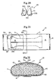
- a preferred embodiment of the disposable absorbent article of the present invention is shown in Figures 1 through 5 as it would be used in a sanitary napkin 10.
- sanitary napkin refers to an article which is worn by females adjacent to the pudendal region and which is intended to absorb and contain menstrual fluids and other vaginal discharges. Interlabial devices which reside partially within the wearer's vestibule are also within the scope of this invention.
- the term "pudendal” refers to the externally visible female genitalia and is limited to the labia majora, the labia minora, the clitoris and the vestibule.
- a preferred sanitary napkin 10 basically comprises a deformation element 20 and an absorbent means 39.
- the absorbent means 39 may be any means which is generally compressible, conformable, non-irritating to the wearer's skin and capable of absorbing and containing liquids and certain body exudates such as menses, blood and urine. If the absorbent means 39 is comprised of more than one constituent part or material, one part or material of the absorbent means 39 may not be absorbent or liquid permeable, so long as the combination of parts or materials has some degree of absorbency and some degree of the properties set forth above.
- the absorbent means 39 has a first major surface 91 and a second major surface 92.
- the deformation element 20 serves as the liquid impermeable backing for the sanitary napkin 10 and has a body facing surface 16, a bottom surface 17, and a periphery 33 which comprises the element side edges 31 and the element end edges 32.
- the absorbent means 39 is superimposed on the deformation element 20 such that the second major surface 92 of the absorbent means 39 is adjacent to the body facing surface 16 of the deformation element 20.
- the absorbent means 39 comprises an absorbent core 40 and a liquid permeable topsheet 45.
- the absorbent core 40 has a first major surface 43, a second major surface 44, core side edges 41 and core end edges 42.
- the absorbent core 40 is superimposed on the deformation element 20 such that the second major surface 44 of the absorbent core 40 is adjacent to the body facing surface 16 of the deformation element 20.
- the topsheet 45 overlays the first major surface 43 of the absorbent core 40.
- the sanitary napkin 10 has a liquid receiving body surface 13 which is generally defined by the topsheet 45 and a garment surface 14 which is generally defined by the bottom surface 17 of the deformation element 20.
- the topsheet 45 and the deformation element 20 have length and width dimensions generally larger than the absorbent core 40 so that they extend beyond the core side edges 41 and the core end edges 42 of the absorbent core 40 where they are associated together in a suitable manner.
- the term "associated” encompasses configurations whereby a first member is directly joined to a second member and configurations whereby a first member is indirectly joined to a second member by affixing the first member to intermediate members which in turn are affixed to the second member.
- the extension of the topsheet 45 and/or the deformation element 20 beyond the core side edges 41 and the core end edges 42 of the absorbent core 40 forms the longitudinal side edges 11 and the end edges 12, respectively, of the sanitary napkin 10.
- the longitudinal side edges 11 and the end edges 12 of the sanitary napkin 10 comprise the periphery 15 of the sanitary napkin 10.
- the topsheet 45 is positioned adjacent the first major surface 43 of the absorbent core 40 and overlays a major portion of the absorbent core 40 so that when exudates are discharged onto the topsheet 45 they will transfer from the body surface 13 of the topsheet 45 through to the absorbent core 40 where they are absorbed by the absorbent core 40.
- the topsheet 45 extends outwardly toward the edges of the absorbent core 40 so that a major portion of the absorbent core 40 is disposed between the topsheet 45 and the deformation element 20. In the preferred embodiment shown in Figures 1 through 5, the topsheet 45 has length and width dimensions generally larger than those of the absorbent core 40.
- the topsheet 45 is compliant, soft feeling, and non-irritating to the wearer's skin. Further, the topsheet 45 is liquid pervious, permitting liquids to readily transfer through its thickness.
- a suitable topsheet 45 may be manufactured from a wide range of materials such as formed thermoplastic films, apertured plastic films, porous foams, reticulated foams, natural fibers (e.g. wood or cotton fibers), synthetic fibers (e.g., polyester or polypropylene fibers) or from a combination of natural and synthetic fibers, with formed films being preferred. Formed films are preferred for the topsheet 45 because they are pervious to liquids and yet non-absorbent.
- the body surface 13 of the topsheet 45 is hydrophilic.
- the hydrophilic body surface 13 helps liquid to transfer through the topsheet 45 faster than if the body surface 13 was not hydrophilic. This diminishes the likelihood that menstrual fluid will flow off the topsheet 45 rather than being absorbed by the absorbent core 40.
- the body surface 13 of the topsheet 45 is made hydrophilic by treating the body surface 13 with a surfactant. It is preferred that the surfactant be substantially evenly and completely distributed throughout the body surface 13 of the topsheet 45. This can be accomplished by any of the common techniques well known to those skilled in the art. For example, the surfactant can be applied to the topsheet 45 by spraying, by padding or by the use of transfer rolls.
- the topsheet 45 may advantageously be provided with a target acquisition zone 46.
- the zone 46 has larger openings and a greater percentage of open area than the remaining regions of the topsheet 45.
- the zone 46 serves two purposes. First, the larger openings and greater open area provide quicker acquisition of fluid gushes which are often experienced when a woman rises from having been seated or lying, whereas blood and menses have accumulated in the vaginal canal or vestibule. Second, the larger openings of the zone 46, as compared to the rest of the topsheet 45, provide more complete acquisition of the sometimes highly viscous menses.
- the zone 46 can be positioned anywhere on the topsheet 45 and can have any shape.
- the zone 46 can be as small as proper functioning will allow or almost as large as the topsheet 45, itself. However, because the larger openings of the zone 46 may not prevent rewet as well as the rest of the topsheet 45, the zone 46 preferably has an area great enough to be in contact with the menses as it exits the vestibule yet not so large as to contact surrounding skin surfaces which could be soiled or irritated by rewet.
- the zone 46 is positioned on the topsheet 45 in an area where menses will contact the zone 46 first before contacting the rest of the topsheet 45. This area is preferably disposed beneath the vestibule and more preferably beneath the vaginal orifice.
- the target acquisition zone 46 is symmetrically located on the topsheet 45 due to the fact that the preferred embodiment of the napkin 10 shown is designed symmetrically so that the napkin 10 and the target acquisition zone 46 will function properly, when worn, no matter which direction the napkin 10 is worn.
- the perimeter of the target acquisition zone 46 is defined by an inner perimeter region 47.
- the inner perimeter region 47 is impervious.
- the inner perimeter region 47 may be formed by thermomolding a polymeric topsheet 45 to a polymeric fiber absorbent core 40 or by gluing or fusing a topsheet 45 to a fluff pulp absorbent core 40.
- the inner perimeter region 47 is not primarily intended for the function of defining the outer perimeter of the zone 46, but, instead is intended to hold the topsheet 45 in contact with the absorbent core 40 so that the topsheet 45 will not shift or roll, and also so that the absorbent core 40 will stay in place and have better integrity.
- the inner perimeter region 47 may not be liquid impervious but will function equally well if it is liquid pervious.
- the configuration of the inner perimeter region 47 is made to correspond to the outline of the protuberance 71 of the deformation element 20, which will be explained in more detail later in this specification.
- the inner perimeter region 47 creates a slight trough around the zone 46 causing the zone 46 to have a somewhat pillowing effect.
- the deformation element 20 has dimples in regions which correspond to the inner perimeter region 47 and which extend through the absorbent core 40, in which case the topsheet 45 is thermomolded or glued directly to the dimples.
- the absorbent core 40 may be any means which is generally compressible, conformable, non-irritating to the wearer's skin, and capable of absorbing and containing liquids and certain body exudates.
- the absorbent core 40 may be manufactured in a wide variety of sizes and shapes (e.g., rectangular, hourglass, etc.) and from a wide variety of liquid absorbent materials commonly used in disposable sanitary napkins, diapers and other absorbent articles, such as comminuted wood pulp which is generally referred to as airfelt and which is preferred.
- suitable absorbent materials include creped cellulose wadding, absorbent foams, absorbent sponges, super absorbent polymers, absorbent hydrogel materials, polymeric fibers, or any equivalent materials or combinations of materials.
- the total absorbent capacity of the absorbent core 40 should, however, be compatible with the design exudate loading for the intended use of the absorbent article. Further, the size and absorbent capacity of the absorbent core 40 may be varied to accommodate wearer's ranging in size and also ranging in the expected amount of exudate fluid volume. For instance, a different absorbent capacity may be utilized for sanitary napkins intended for daytime use as compared with those intended for nighttime use or for sanitary napkins intended for use by teenage females as compared with those intended for use by more mature women.
- a preferred embodiment of the sanitary napkin 10 has a generally rectangular shaped absorbent core 40 having rounded end edges 42 and is intended to be worn by generally all females.
- the absorbent core 40 is preferably a batt of airfelt having a laminate of hydrogel forming material 37 adjacent to and underlaying the airfelt fibers.
- Suitable hydrogel forming materials are disclosed in U.S. Patent 4,654,039, entitled “Hydrogel-Forming Polymer Compositions For Use In Absorbent Structures", which patent issued to Brandt, Goldman and Inglin on March 31, 1987.
- the batt of airfelt is about 6.0 centimeters wide (lateral dimension) and about 19.0 centimeters long (longitudinal dimension).
- the absorbent core 40 has a generally uniform caliper of about 4.6 millimeters, an absorbent capacity of from about 4.0 grams to about 10.0 grams of water per gram of absorbent material and a density of about 0.1 grams per cubic centimeter. It should be understood, however, that the size, shape, configuration, and total absorbent capacity of the absorbent core 40 may be varied to accommodate wearer's ranging in size and expected fluid flow. Therefore, the dimensions, shape, and configuration of the absorbent core 40 may be varied (e.g., the absorbent core may have a varying caliper or a hydrophilic gradient).
- the deformatlon element 20 is flexure-resistant.
- the term "flexure-resistant" refers to an element which will support a bending moment, in contrast to an element which will support only axial forces.
- the deformation element 20 of the present invention has a preference for having a convex upward configuration when the napkin 10 is subjected to lateral compressive forces 100, when worn.
- the deformation element 20 of the present invention will have a convex upward configuration when the sanitary napkin 10 is worn by different females wearing the same designed napkin 10 for a period of fifteen minutes in at least seventy of one-hundred trials.
- the wearer may have to initially manipulate the element 20 into a convex upward configuration either prior to or just after placement of the napkin 10 to the wearer's body.
- the deformation element 20 is manufactured from a moldable substance. More preferably the element 20 is manufactured from a thermomoldable substance, and most preferably a radiation cross-linked polyethylene foam. Such a foam is manufactured by Voltek, Inc. of Lawrence, Massachusetts, and marketed in the trade as Voltek Volara Type 2A. Another suitable foam is a thermomoldable cross-linked closed cell polyolefin which is manufactured by Dynamit Nobel of America, Inc. of South Holland, Illinois, and marketed in the trade as Dynamit Nobel Trocellen Type XJV400.
- a preferred deformation element 20 has a caliper of from about 1 .25 to about 2.5 millimeters and more preferably from about 1 .75 to about 2.0 millimeters.
- a preferred element 20 is formed from a polyethylene foam sheet which is subsequently subjected to molding by a known thermomolding process. The sheet is subjected to thermomolding at a temperature of from about 110°C to about 205°C to form the element 20.
- Other suitable foams are made from such substances as polyethylene, polypropylene, polyester, polybutylene, ethylene vinyl acetate, polyurethane, thermobondable cellulose, latex, silicone elastomerics and others. However, the element 20 need not be made of foam.
- the element 20 could be made of fibers, films or sheets of cellulose, rayon, nylon, polyester, stiffened cotton, polyethylene, vinyl acetate, latex, rubber, plastic, heavy-weight paper such as cardboard, coated paper, or a combination or laminate of these or other materials. Further, if the element 20 is susceptible to being wetted when worn, then the element 20 must be moisture stable. In other words, elements which are susceptible to wetting when worn and are not moisture stable, but instead are moisture unstable, are not within the scope of the present invention.
- moisture unstable refers to materials which are held together solely by hydrogen bonds and/or fibrous structures comprised of short fibers having a length of 10.0 millimeters or less which are held together by mechanical entanglement and frictional forces.
- An example of a material which is held together solely be hydrogen bonds is standard toilet tissue which is a slurry of wood pulp laid on a screen and subjected to drying.
- An example of a material which is held together by mechanical entanglement and frictional forces is short-fiber fluff pulp which is air-laid and then compressed or densified to promote interfiber entanglement.
- a material is bonded at least partially through means other than hydrogen or short-fiber mechanical entanglement and frictional forces, then the material is moisture stable.
- Examples include short wood pulp fibers which are adhesively held together, foams having chemical bonds other than just hydrogen, long synthetic fibers suitably blended with short-fiber wood pulp and others.
- the reason that the element 20 must be moisture stable is that in order for the element 20 to provide continuing benefit when worn and soiled, the element 20 should maintain a functional degree of flexure-resistance throughout a normal wearing time.
- the deformation element 20 does not consist solely of a single homogenous material.
- the element 20 may be comprised of fluff pulp having unbonded regions and selected adhesively bonded regions which impart to the element 20 a flexure-resistance.
- the element 20 may be comprised of fluff pulp having thin strips or a lattice of foam material dispersed throughout the fluff pulp to provide flexure-resistance.
- the element 20 may be a polymeric sheet having a stiffening grid bonded to it to provide flexure-resistance.
- the element 20 has a flexure-resistance measured by peak bending stiffness of at least about 100.0 grams. More preferably, the deformation element 20 has a peak bending stiffness of greater than about 200.0 grams, and most preferably greater than about 350.0 grams. Depending on the element's 20 design, peak bending stiffnesses of greater than 500.0 grams have been found acceptable. As an element increases in flexure-resistance, it generally maintains its shape better, but it also generally becomes more uncomfortable and increases wearing awareness.
- Peak bending stiffness is determined by a test which is modeled after the ASTM D 4032-82 CIRCULAR BEND PROCEDURE, the procedure being considerably modified and performed as follows.
- the circular bend procedure is a simultaneous multi-directional deformation of a material in which one face of a specimen becomes concave and the other face becomes convex.
- the circular bend procedure gives a force value related to flexure-resistance, simultaneously averaging stiffness in all directions.
- the apparatus necessary for the CIRCULAR BEND PROCEDURE is a modified Circular Bend Stiffness Tester, having the following parts: Two smooth-polished steel plate platforms which are 102.0 x 102.0 x 6.35 millimeters, one having an 18.75 millimeter diameter orifice and the other having a 31.75 millimeter diameter orifice.
- the lap edge of each orifice should be at a 45 degree angle to a depth of 4.75 millimeters.
- a plunger having an overall length of 72.2 millimeters, a diameter of 6.25 millimeters, a ball nose having a radius of 2.97 millimeters and a needle-point extending 0.88 millimeter therefrom having a 0.33 millimeter base diameter and a point having a radius of less than 0.5 millimeter, the plunger being mounted concentric with the orifice and having equal clearance on all sides.
- the needle-point is merely to prevent lateral movement of the test specimen during testing. Therefore, if the needle-point significantly adversely affects the test specimen (for example, punctures an inflatable structure), then the needle-point should not be used.
- the bottom of the plunger should be set well above the top of the orifice plate.
- a force-measurement gauge and more specifically an Instron inverted compression load cell.
- the load cell has a load range from about 0.0 to about 2000.0 grams.
- An actuator and more specifically the Instron Model No. 1122 having an inverted compression load cell.
- the Instron 1122 is made by the Instron Engineering Corporation, Canton, Massachusetts.
- each constituent part should be tested separately, if feasible, and also, the element should be tested as a whole. From one of the five elements to be tested, some number "Y" of 37.5 x 37.5 millimeter test specimens are cut. If any portion of the element meets the parameters of this test, then the element as a whole satisfies the test. Therefore, a number "Y" of different specimens should be tested from each element. Certainly, the structurally most rigid portion of the element should be tested.
- a test specimen is cut from a portion of the element which has a convex upward configuration, as later described.
- portions of the elements which are not 37.5 x 37.5 millimeters.
- the test specimens should not be folded or bent by the test person and the handling of specimens must be kept to a minimum and to the edges to avoid affecting flexural-resistance properties.
- an equal number "Y" of 37.5 x 37.5 millimeter specimens identical to the specimens cut from the first element are cut.
- the test person should have "Y" number of sets of five identical specimens.
- the procedure for the CIRCULAR BEND PROCEDURE is as follows.
- the specimens are conditioned by leaving them in a room which is 21 ⁇ 1°C and 50 ⁇ 2% relative humidity for a period of two hours. It has been recognized that specimens having an uncompressed optical caliper of 6.35 millimeters or greater tend to bunch up in the 18.75 millimeter test plate orifice and thereby give readings which are more related to the specimen's compression resistance rather than the specimen's flexure-resistance. Thus, specimens having an uncompressed optical caliper of 6.35 millimeters or greater should be tested using the test plate having the orifice of 31.75 millimeters.
- the tester plate is leveled.
- the plunger speed is set at 50.0 centimeters per minute per full stroke length.
- a specimen is centered on the orifice platform below the plunger such that the body facing surface 16 of the specimen is facing the plunger and the bottom surface 17 of the specimen is facing the platform.
- the indicator zero is checked and adjusted, if necessary.
- the plunger is actuated. Touching the specimen during the testing should be avoided. The maximum force reading to the nearest gram is recorded. The above steps are repeated until all five of the specimens have been tested.
- the peak bending stiffness for each specimen is the maximum force reading for that specimen.
- "Y" number of sets of five identical specimens were cut. Each set of five identical specimens are tested and the five values received are averaged. Thus, the test person now has an average value for each of the "Y" sets tested.
- the flexure-resistance for a particularly designed element is the greatest of these average peak bending stiffnesses.
- the deformation element 20 is positioned such that the body facing surface 16 of the deformation element 20 is adjacent to the second major surface 44 of the absorbent core 40.
- the deformation element 20 is substantially liquid impermeable and serves as the liquid impermeable backing of the sanitary napkin 10.
- the deformation element 20 underlays a major portion of the absorbent core 40 so that exudates which are absorbed by and contained within the absorbent core 40 are prevented from soiling adjacent garments and linens.
- the deformation element 20 has length and width dimensions generally larger than the absorbent core 40 so that the deformation element 20 extends beyond the core side edges 41 and the core end edges 42 to the longitudinal side edges 11 and the end edges 12, respectively, of the sanitary napkin 10 where it is associated with the topsheet 45.
- the topsheet 45 and the deformation element 20 are heat-sealed to each other near and along the periphery 15 of the sanitary napkin 10.
- the foam element 20 has a closed-cell construction on its body facing surface 16 so that it is non-absorbent.
- the foam element 20 may be of an open-cell construction on its body facing surface 16 so that it is absorbent.
- the element 20 should be substantially liquid impermeable.
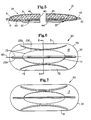
- a preferred deformation element 20 of the sanitary napkin 10 shown in Figures 1 through 5 is shown in Figures 6 through 8.
- the element 20 has a length of about 20.5 centimeters, a width of about 8.0 centimeters and a generally uniform caliper of about 2.0 millimeters, except for the flexure hinges 23A, 23B and 23C which have a caliper of about 1.25 millimeters.
- the deformation element 20 has a flexure means 23 for inducing the deformation element 20 to bend in a preconceived way into a preconceived geometric configuration when the sanitary napkin 10 is subjected to lateral compressive forces 100 when worn. There are a number of possible flexure means 23.
- a preferred flexure means 23 are the flexure hinges 23A, 23B and 23C shown in Figures 6 through 8.
- a flexure hinge initiates deformational development of preconceived geometric configurations.
- a flexure hinge creates different bend-resistances across the width of the deformation element 20.
- the difference in bend-resistance can be created by geometric discontinuities in the element 20 as by pre-set folds, scoring, indentations, perforations, or fairly abrupt changes in elevation.
- the difference can also be created by changes in bend-resistance across the width of the element 20 due to changes in material properties of the element 20 as by localized compaction or by the combination of different materials across the width of the element 20, wherein the materials have different flexure-resistances.
- the flexure hinges 23A, 23B and 23C induce the deformation element to have a convex upward configuration when the napkin 10 is worn.
- the convex upward configuration of the element 20 causes the absorbent core 40 and the topsheet 45 to also have a convex upward configuration, and consequently, the body surface 13 of the napkin 10 has a convex upward configuration when the napkin 10 is worn.
- the preferred embodiment of the element 20 shown in Figures 6 through 8 has a linear central hinge 23A, a pair of curvilinear thigh hinges 23B, and a pair of curvilinear protuberance hinges 23C, all of which are of the geometric discontinuous type and all of which have been thermomolded into the element 20.
- the element 20 slopes inwards and downwards to form walls 72 having bases 74 which are adjacent to the curvilinear thigh hinges 23B.
- the walls 72 comprise that portion of the element 20 between the thigh hinges 23B and the element side edges 31.
- the walls 72 have a pudendal facing surface 73.
- Figures 6 and 7 illustrate that the thigh hinges 23B extend generally longitudinally and curve inward from the element side edges 31 so as to approximate the curvature of a wearer's thighs.
- the thigh hinges 23B are arcuate, wherein the midpoint of the arc is the greatest distance from the element side edges 31.
- the thigh hinges 23B have a generally "U" shaped cross-section as shown in Figure 8.
- Adjacent to the longitudinal midpoint of the thigh hinges 23B are the curvilinear protuberance hinges 23C which serve to define the perimeter of the protuberance 71 of the element 20 as shown in Figures 6 and 7.
- the protuberance hinges 23C are arcuate wherein the midpoint of the arc is the greatest distance from the longitudinal axis 90.
- the protuberance hinges 23C are formed into the element 20 as a result of the thermomolding formation of the protuberance 71.
- the protuberance hinges 23C are the result of a fairly abrupt change in elevation across the element 20.
- the element 20 curvilinearly slopes upward to the linear central hinge 23A, thus forming a protuberance 71.
- the protuberance 71 is provided to promote and initiate some of the desired bending deformations of the element 20 and, in particular, the protuberance 71 predisposes the element 20 to bend in such a way that the body facing surface 16 of the element 20 will have a convex upward configuration when the napkin 10 is subjected to lateral compressive forces 100 when worn, as will be later explained.
- the protuberance 71 need not be provided and, in fact, the element 20 can be planar or downwardly cup shaped.
- such configurations might require a more complex design that might require more compressive force and more mechanical action in order to create a convex upward configuration.
- the element 20 need only maintain a convex upward configuration when the napkin 10 is subjected to lateral compressive forces 100, when worn, in contrast to an element 20 that is planar or downwardly cupped shaped when applied but assumes a convex upward configuration when worn.
- the term "maintain” includes embodiments wherein the body facing surface 16 of the element 20 retains the same convex upward configuration that it had prior to the application of lateral compressive forces 100 when worn and embodiments wherein the body facing surface 16 assumes a different convex upward configuration than it had prior to the application of lateral compressive forces 100 when worn.
- an object of the present invention is to put the body surface 13 of the napkin 10 in intimate contact with the external surfaces of the labia majora when worn, the protuberance 71 gives the element 20 and, consequently the napkin 10, some pre-formed elevation to aid in providing such intimate contact.
- the central hinge 23A extends longitudinally along the longitudinal axis 90 of the element 20 nearly from one end edge 32 of the element 20 to the other end edge 32. As shown in Figure 8, the central hinge 23A has a generally inverted "U" shaped cross-section.
- the previous description of the sanitary napkin 10, and particularly the deformation element 20 has been directed to the element's 20 "at rest" configuration. However, when the sanitary napkin 10 is worn, at least a portion of the body facing surface 16 of the deformation element 20 must have a convex upward configuration.
- the term "convex upward configuration” includes embodiments wherein at least a portion of the body facing surface 16 of the deformation element 20 has a convex shape.
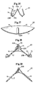
- a "convex upward configuration” is determined as follows, the following explanation being given with reference to Figures 9 through 11.
- two plungers 200 having a radius of about 76.2 millimeters are positioned symmetrically across from each other so that the midpoint of the faces of the plungers 200 are about 25.4 millimeters apart.
- the curvature of the plungers 200 is intended to approximate the curvature of the thighs of a representative number of women.
- the 25.4 millimeters distance is intended to approximate the distance between the thighs of a representative number of women, when standing.
- a top view of two properly positioned plungers 200 is shown in Figure 10.
- the plungers 200 have a face 205 height of about 51.0 millimeters, a bottom lip 220 having a width of about 5.0 millimeters and a thickness of about 5.0 millimeters.
- the napkin With the body surface 13 of the napkin to be tested facing up and the garment surface 14 of the napkin facing down, the napkin is placed between the plungers 200 in the shape that the napkin 10 generally has when worn.
- the napkin may have to be manipulated into its "in use” shape. Often, this "in use” shape can be determined through simple visual observations of females wearing the napkin. If the shape is not determinable through visual observation, at least one feasible alternative that is available is Magnetic Resonance Imaging (MRI).
- MRI Magnetic Resonance Imaging
- Magnetic resonance images of females wearing sanitary napkins which have been saturated with mineral oil have been used to give accurate depictions of the shape a sanitary napkin has when worn.
- a cast molding of the sanitary napkin is made.
- the cast molding is for the purpose of permanently “freezing” the napkin in this "in use” configuration so that the napkin can be further studied.
- the cast mold can be made from a number of different materials. Preferably, the material that is used will penetrate into the absorbent means. Two materials that have been found suitable are a hard-casting material which is marketed as EnviroTex 1 to 1 Polymer Coating by Environmental Technology, Inc.
- the casting material can be poured directly into the napkin if the "in use" configuration is susceptible to such (i.e. for example, boat or cupped shaped). If not, a thin sheet of aluminum foil can be placed around and under the napkin so as to create a receiver for the casting material. The aluminum foil receiver can then be filled so as to submerge the napkin in the casting material. Either way, the napkin should substantially retain its in-use shape.
- any number of lateral cross-sections can be cut along the longitudinal length of the napkin. From these lateral cross-sections, a person can determine whether the napkin has a convex upward configuration by performing the following test, reference being directed to the cast molded lateral cross-section of the napkin 10 shown in Figure 11. While looking directly at a cross-section, if there is a point on the body facing surface 16 of the element 20 that has an elevation of at least about 2.5 millimeters above either outer perimeter of the body facing surface 16, then the body facing surface 16 of the element 20 has a convex upward configuration. If there is such a point, the point is preferably at least about 5.0 millimeters above either outer perimeter of the body facing surface 16.
- the body facing surface 16 of the deformation element 20 has a convex upward configuration.
- the first point 51 has an elevation of at least about 5.0 millimeters above the inflection point 50 and the second point 52 has an elevation of at least about 5.0 millimeters below the first point 51.
- the body facing surface 16 must have at least one convex upward configuration but can have more.
- a portion of the body facing surface 16 of the element 20 in the central region 62 of the element 20 will have a convex upward configuration.
- the portion of the body facing surface 16 of the element 20 which is disposed beneath the center of the vaginal orifice when the napkin 10 is worn will have a convex upward configuration.
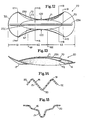
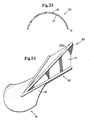
- FIG. 14 A cross-section of an alternatively preferred deformation element 20 embodiment of the present invention having a body facing surface 16 having a convex upward configuration is shown in Figure 14.
- FIG. 15 An example of a deformation element 20 not within the scope of the present invention having a body facing surface 16 but not having a convex upward configuration is shown in Figure 15.
- the sanitary napkin 10, and particularly the deformation element 20 have basically been described in their "at rest” (i.e., not worn) configurations.
- the "at rest” configurations of the napkin 10 and the element 20 will seldom, if ever, be realized when the napkin 10 of the present invention is being worn. Therefore, the following is a description of the different anatomy conforming shapes the deformation element 20 assumes along the element's 20 length when the sanitary napkin 10 is being worn and thereby subjected to the lateral compressive forces 100 of the wearer's thighs.
- the absorbent means 39 which is associated with the element 20, generally flexes in cooperation with the element 20. More specifically, the topsheet 45, which is affixed directly to the element 20 in the periphery 15 of the napkin 10, and the absorbent core 40, which is disposed between the topsheet 45 and the element 20, generally flex in cooperation with the element 20.
- the cross-sectional configurations of the napkin 10 along the napkin's 10 longitudinal length, and specifically of the absorbent means 39, which in the preferred embodiment comprises the topsheet 45 and the absorbent core 40 generally mimic the cross-sectional configurations of the element 20. In other embodiments, the cross-sectional configurations of the napkin 10 and the absorbent means 39 may not mimic the cross-sectional configurations of the element 20.
- the element 20 assumes a generally hourglass shaped top plan view.
- the distance between the lines 81 and 82 or their relative position on the napkin 10 can vary depending upon the size of the wearer and the positioning of the napkin 10.
- the portion of the element 20 extending forward from about the line 81 to the front end edge 32 is the front region 61.
- the portion of the element 20 extending backward from about the line 82 to the back end edge 32 is the back region 63. Note that when underpants are worn, the front region 61 and the back region 63 shown in Figure 13 may be forced to curve upwards (not shown).
- the central region 62 of the element 20 can assume a number of different cross-sections ranging from its at-rest configuration shown by cross-section in Figure 9 to the in-use configuration shown by cross-section in Figure 16.
- the element 20 assumes a generally "W" shaped cross-section in the central region 62.
- the walls 72 have assumed a substantially vertical position.
- the element side edges 31 remain adjacent to the walls 72, but are now displaced to a position above the walls 72 and into the uppermost part of the wearer's legs at the crotch where there is minimum movement and the least cause for irritation.
- the bases 74 of the walls 72 are adjacent to the thigh hinges 23B.
- the thigh hinges 23B are provided to allow the walls 72 to bend about the thigh hinges 23B, thereby assuming a substantially vertical position.
- Valleys 67 are formed above and around where the bases 74 of the walls 72 meet the thigh hinges 23B. The valleys 67 are particularly useful in diffusing exudates lengthwise to better utilize the total absorbent capacity of the napkin 10.
- the element 20 slopes inwards and downwards.
- the body facing surface 16 of the element 20 has a convex upward configuration, and more particularly a generally inverted "U" shaped configuration.
- the element 20, and particularly the protuberance 71 has a generally inverted "U” shaped cross-section.
- the convex upward configuration is generally symmetrically located between the longitudinal side edges 11, which in this embodiment are synonymous with the element side edges 31.
- the linear central hinge 23A is generally symmetrically located between the protuberance hinges 23C, along the longitudinal centerline 90 and along the apex of the convex upward configuration.
- the element's 20 upward movement may be impeded if the body surface 13 of the napkin 10 makes intimate contact with the wearer's pudendal region, and more specifically the external surfaces of the labia majora. If such occurs, the element 20, and specifically in a preferred embodiment the protuberance 71, will deform, and more particularly in a preferred embodiment, spread or bulge outwards.
- a comparison of Figures 16 and 20 illustrates how in a preferred embodiment the protuberance 71 deforms when the protuberance's 71 upward movement is restricted by the external surfaces of the pudendal region.
- the major portion of the front region 61 is generally circular when viewed from above the body facing surface 16.
- the front region 61 remains generally circular because it is located beyond the thighs and is, therefore, not directly affected by the lateral compressive forces 100 which are exerted by the wearer's thighs.
- the region 61 is indirectly affected by the compressive forces 100 of the wearer's thighs and, in consequence thereof, assumes some anatomy conforming shapes.
- the front region 61 of the element 20 has an upwards opening cup shape when the napkin 10 is worn. This shape is depicted by cross-section in Figure 17.
- the curved end edge 32 in the front region 61 along with the flexure hinges 23A, 23B, and 23C facilitate the formation of this cup shape.
- the back region 63 like the front region 61, also assumes some anatomy conforming cross-sections when the napkin 10 is worn. However, in order to adapt to the different shapes of the anatomy in the buttocks region of the wearer, the cross-sections are very different from those in the front region 61.
- the back region 63 is configured to fit the gluteal groove of a wearer when the napkin 10 is worn.
- the body facing surface 16 of the element 20 has a convex upward configuration.
- the back region 63 of the element 20 has a convex upward cross-section. The cross-section of the back region 63 best depicting this shape is shown in Figure 18.
- the central hinge 23A which is at the apex of the convex upward configuration in the central region 62, remains at the apex of the convex upward configuration into the back region 63. Since the napkin 10 will in all probability be worn with an undergarment, such as panties, the upward forces of the undergarment will preferably cause the back region 63 and the rearward part of the central region 62 to curve upwards and follow the curve of the buttocks.
- the body facing surface 16 of the element 20 in the back region 63 has a ridge 70 which is configured to fit the gluteal groove of the wearer, when worn.
- the ridge 70 is generally symmetrically located between the longitudinal side edges 11 of the napkin 10 along the longitudinal centerline 90.
- the ridge 70 fits the gluteal groove of the buttocks to provide stability against sideward shifting of the napkin 10. Because the depth of the gluteal groove varies as it moves from the anus towards the wearer's back, the back region 63 of the element 20 is designed so that it flattens out somewhat and the ridge 70 becomes less pronounced as the ridge 70 nears the end edge 12 of the back region 63. This change in formation is evidence by a comparison of Figure 18, which is a cross-section through the back region 63, with Figure 19, which is also a cross-section through the back region 63 but which is located more towards the end edge 12 of the back region 63.
- the present invention is intended to function and provide the benefits as follows.
- the following is a description of only one means of progressive deformation of the napkin 10 and it should be recognized that other means are available.
- the napkin 10 is placed in the wearer's panties or directly adjacent to the wearer's crotch area so that the body surface 13 of the napkin 10 is facing and generally adjacent to the pudendal region.
- the body facing surface 16 of the element 20, and particularly that portion of the body facing surface 16 which is superimposed over the protuberance 71 has a convex upward configuration, and more specifically, an inverted "U" shaped configuration.
- that portion of the body facing surface 16 having a convex upward configuration in conjunction with the pudendal facing surface 73 of the walls 72, present a generally "W" shaped configuration.
- the body surface 13 of the napkin 10 may make intimate contact with the external surfaces of the pudendal region, thereby causing the element 20 and particularly the protuberance 71 to bulge outwards as shown in Figure 20.
- the element 20 is flexure-resistant, the element 20 and particularly the protuberance 71 provides an outwardly directed biasing force against the downwardly distributed forces 500 of the wearer's pudendal region.
- this biasing force creates a pressure promoted seal between the external surfaces of the labia majora and the body surface 13 of the napkin 10.
- lateral compressive forces 100 are provided by the wearer's thighs to put the body surface 13 of the napkin 10 in intimate contact with the external surfaces of the pudendal region, thereby causing the protuberance 71 of the element 20 to spread or bulge and create a biasing force which thereby seals the body surface 13 of the napkin 10 against the labia majora.
- the front region 61 is simultaneously deforming into an upwards opening cup shape.
- the cup shaped front region 61 serves important functions. First, many women are concerned with the unobtrusiveness of their sanitary napkins when they are standing or laying on their backs since these are the positions when their forward groin area is most openly exposed. Coincidentally, these are also positions in which the wearer's thighs are exerting lateral compressive forces 100 on the napkin 10 and, in response thereto, the front region 61 of the element 20 is curving upwards.
- the napkin 10 of the present invention is already curving upwards around the wearers mons pubis and therefore cooperates with the forces of the undergarments so as to remain as unobtrusive as possible.
- the cup-like shape of the front region 61 which preferably has its edge surface 12 in sealing engagement with the wearer's skin surfaces due to the upward pressure of the wearer's undergarments, provides an excellent retention area for the exudates until they can be absorbed by the absorbent means 39 or until the napkin 10 is discarded.
- the front region 61 may funnel the exudates back towards the valleys 67 in the central region 62, which is an area even less likely to cause soiling due to the protection provided by the vertically standing walls 72.
- menses may flow out of the vaginal orifice and along the surfaces of the labia minora where it may drip or continue to flow onto the mons pubis.
- the cup shape of the front region 61 forms a receiver which is ideal for catching and containing such drips and flows. Further, because the end edge 12 of the front region 61 is preferably in sealing engagement with the wearer's skin, any menses flowing along the skin will contact and be absorbed by, or at least contained by, the end edge 12 before it can leak beyond the end edge 12 of the napkin 10 and soil undergarments or linens.
- the back region 63 is simultaneously deforming into some anatomy conforming configurations when the napkin 10 is worn, as shown in Figures 18 and 19.
- the back region 63 begins to bend downwards about the central hinge 23A, thereby assuming a convex upward configuration which is configured to fit between the buttocks of the wearer and in the gluteal groove.
- the forces of the buttocks on the napkin 10 on each side of the central hinge 23A further facilitate the development of this convex upward configuration.
- a ridge 70 which is configured to fit the gluteal groove of the wearer.
- the ridge 70 provides stability against sideward shifting of the napkin 10.
- the ridge 70 also serves another important function. When a woman lies on her back, as when sleeping, some of the menses may not be deposited directly from the vaginal orifice onto the napkin 10. Instead, the menses may gravitate towards the posterior commissure of the vestibule, following these skin surfaces into the perineal groove, across and around the anus, and into the gluteal groove and the surrounding surfaces of the buttocks where it can soil undergarments and other linens.
- the element 20 of the present invention and especially the back region 63, is designed such that the ridge 70, or an absorbent means 39 which might be superimposed over the ridge 70, will preferably be within the gluteal groove, preferably in contact with the wearer's skin surfaces so that any menses flowing along these skin surfaces will contact the ridge 70, or an absorbent means 39 which is superimposed over the ridge 70, and be absorbed into it before coming in contact with undergarments or other linens.
- the self-conforming characteristics of the sanitary napkin 10 of the present invention render unnecessary a requirement for independent attaching means for the napkin 10 for some wearers and for some embodiments.
- the slight biasing force provided by the wearer's undergarments coupled with the outwards biasing force of the element 20 against the wearer's thighs will establish a sufficient means for maintaining the sanitary napkin 10 in the desired position.
- attachment directly to the undergarment or body is not required, recognizing that such attachment may under some circumstances override the more preferred direct association of the napkin 10 solely with the wearer's body; the wearer then facing the possibility that movement of the undergarment relative to the pudendum will translate into some motion within the napkin 10 itself.
- an adhesive member for securing the napkin 10 to the undergarments of the wearer is most preferably a conventional pressure sensitive adhesive bearing a release paper which may be removed to expose the adhesive for purposes of attachment to an undergarment.
- the wearer may exercise the option of attaching the napkin 10 or not as a matter of individual preference. It is noteworthy that even in those instances where the option to secure the napkin 10 to the undergarment is elected, a comparatively small amount of adhesive in a few locations or zones is most preferably provided as opposed to more conventional longitudinal, multiple strips or the like.
- the napkin 10 of the present invention assumes a number of cross-sections along its longitudinal length which are very different from the original configuration of the napkin 10, it is advantageous when determining where to place adhesive to find points on the garment surface 14 of the napkin 10 which retain their relative position with respect to the wearer's undergarment, when worn.
- Preferred locations for attachment of adhesive for the napkin 10 shown in Figures 1 through 5 are on the bottom surface 17 of the element 20 along a short central length of the thigh hinges 23B and/or an oval patch across the ends of the central hinge 23A near each of the ends 32 of the napkin 10.
- This approach provides a generally acceptable compromise for those who wish the security of attachment of the napkin 10 to the undergarment while those points of attachment are selected as the least influential relative to the potential contribution to rubbing or chafing occasioned by relative motion between the undergarment (and attached napkin) and the wearer's pudendum.
- the deformation element 20 is reformable.
- the term "reformable" refers to the ability of an element to return substantially to a configuration the element held prior to the influence of certain external forces. The element may reform because of the influence of other external forces and/or because of the physical properties of the material of which the element is comprised.
- the deformation element 20 is resilient.
- the term "resilient” refers to an element which after the removal of external forces will return substantially to a configuration the element held prior to the influence of external forces, solely because of the physical properties of the material of which the element is comprised.
- An example will help clarify and differentiate the terms "reformable” and "resilient.”
- a flat, rectangular shaped object Now imagine that the object is squeezed from the sides so that its sides are displaced inwards towards each other and its middle bulges up. Now imagine that the squeezing forces are relieved. If the object returns substantially to its original flat, rectangular shape, then the object is resilient.
- the object If the object returns substantially to its original flat, rectangular shape only after the influence of some other external force, such as by pressing down on the bulge, then the object is reformable, but not resilient.
- a resilient element is necessarily reformable but a reformable element may not be resilient.
- the external forces which render the deformation element 20 reformable are the lateral compressive forces 100 of the wearer's thighs, the downwardly distributed forces 500 of the wearer's pudendum, the forces of the wearer's panties and possibly other external forces which act upon the napkin 10 from, for example, a chair or bed when the wearer sits or lays.
- the absorbent means 39 flex generally in cooperation with the deformation element 20.
- the absorbent means 39 generally mimics such deformations.
- the lateral compressive forces 100 are lessened or relieved, such as when the wearer's thighs are spread, the reformable or resilient nature of the deformation element 20 is realized and the deformation element 20 begins to reform substantially to the shape the element 20 had prior to the influence of the external lateral compressive forces 100.
- the absorbent means 39 preferably reforms to the shape the absorbent means 39 had prior to the influence of external forces.
- external forces which are being exerted on and relieved from the napkin 10 cause the napkin 10 as a whole, and the deformation element 20 and the absorbent means 39 individually, to go through a multitude of deformations and reformations.
- the body facing surface 16 of the element 20 does not have a preformed convex upward configuration like the preferred element 20 described earlier and illustrated in Figures 6 through 8, but instead is planar across its width or has a concave downward configuration.
- the body facing surface 16 must assume a convex upward configuration after the application of lateral compressive forces 100 to the longitudinal side edges 11 of the napkin 10 by the wearer's thighs.
- FIG. 21 and 22 Another alternative embodiment of the sanitary napkin 10 of the present invention is shown in Figures 21 and 22.
- the deformation element 20 is disposed between a liquid pervious topsheet 45 and an absorbent core 40.
- a liquid impervious barrier sheet 55 is provided adjacent to the second major surface 44 of the absorbent core 40 so as to prevent the exudates absorbed and contained in the absorbent core 40 from soiling articles such as bedsheets and undergarments which contact the napkin 10.
- the barrier sheet 55 extends slightly beyond the core end edges 42 and is folded about halfway up the core side edges 41 to prevent leakage.
- the absorbent core 40 is superimposed onto an adhesive which is applied to the inner surface of the barrier sheet 55 and which is intended to hold the barrier sheet 55 in place on the absorbent core 40.
- the topsheet 45 extends around the side edges 41 of the absorbent core 40 and over the barrier sheet 55 where it overlaps itself on the garment surface 14 of the napkin 10 so as to completely envelope the element 20, the absorbent core 40, and the barrier sheet 55, thereby forming what is commonly known as a "tubular napkin".
- the overlapping portions of the topsheet 45 are adhered to each other along the garment surface 14 of the napkin 10 and the end edges of the topsheet 45 and the barrier sheet 55 are heat-sealed to each other to form the end edges 12 of the napkin 10.
- the element 20 comprises wood pulp fibers which have been compressed into a semi-rigid paper-board-like sheet and suitably bonded so as to be moisture stable.
- the element 20 could be comprised of many of the materials previously described. Because this element 20 has a greater flexure-resistance than the element 20 previously described and because it is smaller and has fewer flexure means 23, and particularly fewer flexure hinges, than the element 20 previously described, it is somewhat less body conforming than the previous element 20.
- the flexure means 23 is a longitudinal flexure hinge which, in this embodiment, is simply a longitudinal set 23E to the element 20 (i.e., a preferential fold or crease, scoring, embossing or indenting) along the longitudinal axis 90, which tends to pitch the element 20 upwardly along the fold, thus causing the element 20 to assume a somewhat flattened, inverted "V" shaped cross-section having a ridge 70, as shown in Figure 22.
- the element 20 is placed in the napkin 10 in this configuration so that when the napkin 10 is worn, the element 20 will fold in a controlled and predetermined manner such that the body facing surface 16 of the element 20 will have a convex upward configuration.
- the lateral compressive forces 100 of the wearer's thighs may be applied to the element side edges 31 directly or they may be applied indirectly by transmission of the forces 100 from the longitudinal side edges 11 of the napkin 10 through other members of the napkin 10.
- the lateral compressive forces 100 of the thighs cause the element 20 to assume a more defined, inverted "V" shaped cross-section.
- the element 20 has a generally hourglass shape.
- the hourglass shape offers unique benefits, when worn, in that the inwardly curved middle portion will accommodate the wearer's thighs while the wider end portions, which resultingly have a greater surface area for acquisition of menses and a greater cross-sectional absorptive capacity than the thinner middle portion, are positioned so that when worn the forward end portion will be aligned with and be beneath the vaginal orifice.
- the element 20 has a thickness of about 2.0 millimeters, a length along the longitudinal axis 90 of about 19.0 centimeters, a width across the ends of about 6.5 centimeters and a width across the lateral axis 80 of about 4.0 centimeters.
- an element 20 is shown in Figure 23.
- this element 20 is preferably comprised of a foam material and is flexure-resistant, reformable and resilient.
- the element 20 in its at rest configuration has a convex upward configuration.
- the flexure means 23 of the element 20 is inherent in the element 20 simply due to its preformed arcuate shape. Thus, when lateral compressive forces 100 are applied to the element side edges 31, the element 20 simply maintains a convex upward configuration as it flexes.
- the element 20 is preferably overlayed by an absorbent core 40 and a topsheet 45, which are superimposed on the element 20.
- FIG. 24 Another alternatively preferred embodiment of a deformation element 20 of the present invention is shown in Figure 24.
- the deformation element 20, as shown, is comprised of a foam as previously described.
- the deformation element 20 has a pre-formed inverted "U" shape in the central region 62 and a pre-formed upward conical shape in the front region 61.
- the flexure means 23 is a longitudinally extending linear central hinge 23A having a generally inverted "U" shaped cross-section.
- the element 20 acts much like the element 20 shown in Figures 6 through 8 under lateral compressive forces 100, the main differences being that the element 20 in this alternatively preferred embodiment has a greater degree of pre-formed shape and also, this element 20 is not symmetrical in the longitudinal direction and would, therefore, have to be consciously positioned on the wearer so that it was aligned in the proper direction. Further, this element 20 is not intended to be a liquid impermeable backing member for the napkin 10. Instead, the element 20 has an hourglass shaped absorbent core 40 placed on its body facing surface 16 and a liquid impervious barrier sheet 55 covering its bottom surface 17 and extending beyond its side edges 31 and end edges 32 (not shown). The absorbent core 40 is covered by a liquid pervious topsheet 45 which extends beyond the edges of the absorbent core 40 and the element 20 where it is affixed to the barrier sheet 55 (not shown).
- the deformation element 20 is isolated from contact with moisture.
- such an embodiment might comprise from the body surface 13 down a liquid permeable topsheet 45, an absorbent core 40, a liquid impermeable barrier sheet 55, a deformation element 20, and another liquid impermeable barrier sheet 65, the sheets 45, 55 and 65 being sealed about their peripheries.
- the deformation element 20 is not susceptible to being wetted when worn and thus, the deformation element 20 may be comprised of moisture unstable materials such as compressed, unbonded fluff pulp.
- FIG. 25 Yet another alternatively preferred embodiment of a sanitary napkin 10 and specifically a deformation element 20 of the present invention is shown in Figure 25.
- the napkin 10 comprises a barrier sheet 55, an absorbent core 40 and a topsheet 45 (not shown).
- the absorbent core 40 is comprised of fluff pulp.
- the fluff pulp is embossed in a lattice pattern 82 such that the lattice members 86 are highly densified.
- the fluff pulp is adhesively bonded throughout the middle portion 84 by a water insoluble adhesive.
- the deformation element 20 of the present invention is said to be the middle portion 84 of the absorbent core 40.
- the fluff pulp can be bonded or unbonded beyond the middle portion 84.
- the absorbent core 40 has a preferential set (not shown) on its second major surface 44 along the longitudinal axis 90 so that the deformation element 20 is inclined to have a convex upward configuration when the sanitary napkin 10 is worn.
- the absorbent core 40 is about 20.5 centimeters long, about 13.0 centimeters wide, about 1.0 centimeters thick in the unembossed areas and about 0.5 centimeters thick in the embossed areas.
- the middle embossed portion 84 of the absorbent core 40 is about 10.0 centimeters long and about 6.3 centimeters wide.
- the embossed lattice members 86 are about 3.0 millimeters wide.
- the sanitary napkin 10 comprises, from the body surface 13 down, a topsheet 45, a wipe acquisition sheet 93, a tissue layer 94, an absorbent core 40, a barrier sheet 55, and a deformation element 20.
- the deformation element 20 is centered in the napkin 10.
- the deformation element 20 of this embodiment is generally similar to the midportion of the deformation element 20 shown in Figures 6 and 7.
- the deformation element 20 is affixed to the garment facing surface of the barrier sheet 55.
- the deformation element 20 might be disposed In a number of positions throughout the laminates of the napkin 10, such as between the absorbent core 40 and the barrier sheet 55. Beyond the ends 32 of the deformation element 20, the sanitary napkin 10 is highly flexible. Further, the napkin 10 has a relatively very thin caliper, especially beyond the ends 32 of the element 20.
- the topsheet 25 is an apertured formed film
- the wipe acquisition sheet 93 is an apertured nonwoven sheet, such as the SONTARA 8407, manufactured by E.I. DuPont Nemours & Company of Wilmington, Delaware, (SONTARA Registered Trademark by E.I. DuPont Demours & Company)
- the tissue layer 31 is a wet-laid tissue such as that disclosed in U.S.
- the napkin 10 when subjected to the forces of the wearer's body, when worn, takes on a number of the beneficial shapes of the napkins 10 previously described.
- This embodiment is particularly useful for the following reason.
- the deformation element 20, and the areas of the napkin 10 superimposed over the element 20, take on a convex upward configuration beneath the vestibule and specifically beneath the vaginal orifice.
- the napkin 10 is able to acquire menses immediately as it exits the vestibule.
- the napkin 10 is highly flexible and very thin.
- the napkin 10 is extremely comfortable, has a low wearing awareness, and conforms very nicely to the mons pubis and the gluteal groove.
Abstract
Description
- The present invention relates to disposable absorbent articles and more particularly to female sanitary napkins. Particularly, the present invention concerns sanitary napkins offering enhanced fit and comfort through a construction which promotes a continuously self-conforming anatomical cooperation of the sanitary napkin to the wearer to yield a highly effective absorbent device.
- All manner and variety of absorbent articles configured for the absorption of body fluids such as menses, urine and feces are, of course, well known. With respect to feminine protection devices, the art has offered two basic types; sanitary napkins have been developed for external wear about the pudendal region while tampons have been developed for internal wear within the vaginal cavity for interruption of menstrual flow therefrom. Such tampon devices are disclosed In U.S. Patent 4,412,833, entitled "Tampon Applicator", which patent issued to Wiegner et al. on November 1, 1983, and U.S. Patent 4,413,986, entitled "Tampon Assembly With Means For Sterile Insertion", which patent issued to Jacobs on November 8, 1983.
- Hybrid devices which attempt to merge the structural features of the sanitary napkins and the tampons into a single device have also been proposed. Such hybrid devices are disclosed in U.S. Patent 2,092,346, entitled "Catamenial Pad", which patent issued to Arone on September 7, 1937, and U.S. Patent 3,905,372, entitled "Feminine Hygiene Protective Shield", which patent issued to Denkinger on September 16, 1975. Other less intrusive hybrid devices are known as labial or interlabial sanitary napkins and are characterized by having a portion which at least partially resides within the wearer's vestibule and a portion which at least partially resides external of the wearer's vestibule. Such devices are disclosed in U.S. Patent 2,662,527, entitled "Sanitary Pad", which patent issued to Jacks on December 15, 1953, and U.S. Patent 4,631,062, entitled "Labial Sanitary Pad", which patent issued to Lassen et al. on December 23, 1986.
- With respect to sanitary napkins, at least three general classes of design exist. One such design includes those sanitary napkins which are generally cupped or boat-shaped and which are intended to catch menses as it runs or drips from the vaginal orifice. These sanitary napkins generally bow downwards, when worn, thus forming a cup-shape. Sanitary napkins of this class are disclosed in U.S. Patent 3,570,493, entitled "Sanitary Towel", which patent issued to Olson on March 16, 1971, and U.S. Patent 4,655,759, entitled "Reduced Leakage Menstrual Pad With Built-In Fold Lines", which patent issued to Romans-Hess et al. on April 7, 1987. A disposable urinary incontinence device which functions under the same principal is disclosed in U.S. Patent 4,685,914, entitled "Disposable Urinary Pad", which patent issued to Holtman on August 11, 1987.
- A second class of sanitary napkin designs include those that are raised upwardly or humped in their medial portions so as to be near or in contact with the pudendal region when worn. These sanitary napkins attempt to contact and absorb menses immediately as it leaves the vestibule. Sanitary napkins of this class are disclosed in U.S. Patent 2,064,431, entitled "Catamenial Bandage", which patent issued to Jurgensen on December 15, 1936, U.S. Patent 2,747,575, entitled "Catamenial Bandages", which patent issued to Mercer on May 29, 1956, U.S. Patent 3,575,174, entitled "Sanitary Napkin", which patent issued to Mogor on April 20, 1971 and U.S. Patent 4,701,177, entitled "Three-Dimensional Shaped Feminine Pad With Narrow, Absorbent Center and Winged Edges", which patent issued to Ellis et al. on October 20, 1987.
- The third class of sanitary napkin designs include those that are not predisposed to have a trough or a hump shape when worn, but instead have a more or less, rope-like shape when worn. Such sanitary napkins typically have a fluff pulp absorbent core surrounded by flexible outer wraps and when the sanitary napkin is subjected to compressive forces from the wearer's thighs the fluff pulp core simply compacts or bunches into an arbitrary, but generally rope-like shape. Sanitary napkins of this class are disclosed in U.S. Patent 3,294,091, entitled "Sanitary Napkin", which patent issued to Morse on December 27, 1966, U.S. Patent 4,654,040, entitled "Smooth-Edged Contoured Sanitary Napkin", which patent issued to Luceri on March 31, 1987, and U.S. Patent 4,687,478, entitled "Shaped Sanitary Napkin With Flaps", which patent issued to Van Tilburg on August 18, 1987. Attempts have been made to prevent the bunching effect of such compaction type sanitary napkins by providing them with a form-retaining member. Such sanitary napkins are disclosed in U.S. Patent 4,195,634, entitled "Sanitary Napkin With Resilient Stiffening Means", which patent issued to DiSalvo et al. on April 1, 1980, and U.S. Patent 4,405,326, entitled "Catamenial Bandage", which patent issued to Lenaghan on September 20, 1983.
- While the sanitary napkins and other devices discussed above do provide some measure of success in absorbing and containing body exudates, they fail to address the need for a sanitary napkin which by the mere act of putting it on will itself merge in with, closely conform to and fit exactly the cross-sectional outline of the pudendal region as soon as applied without requiring the usual bending, twisting or other adjustments or manipulations, and which will always retain such conformity simply due to its flexure-resistant, reformable and resilient characteristics.
- Therefore, it is an object of the present invention to provide a sanitary napkin which by the mere act of putting it on will itself merge in with, closely conform to, and fit exactly the cross-sectional outline of the external surfaces of the pudendal region.
- It is an additional object of the present invention to provide a sanitary napkin which will change its shape so as to conform to the changing shape of the pudendal region when the wearer is running, squatting, crossing her legs, etc.
- It is an additional object of the present invention to provide a sanitary napkin having a flexure-resistant deformation element which causes the body surface of the sanitary napkin to remain in intimate contact with the external surfaces of the labia majora.
- It is an additional object of the present invention to provide a sanitary napkin having a flexure-resistant deformation element having a body facing surface wherein the body facing surface of the deformation element has a convex upward configuration when the napkin is subjected to the lateral compressive forces of the wearer's thighs.
- It is an additional object of the present invention to provide a sanitary napkin having a flexure-resistant deformation element having a body facing surface wherein the body facing surface is generally cupped-shaped in the front region, generally "W" shaped in the central region and generally inverted "V" shaped in the back region of the deformation element.
- These and other objectives of the present invention will be more readily apparent when considered in reference to the following description and when taken in conjunction with the accompanying drawings.
- The present invention is directed to a disposable absorbent article, and particularly a sanitary napkin, having a flexure-resistant deformation element, the deformation element having a body facing surface which has a convex upward configuration when the sanitary napkin is worn. Primarily without relying on lateral compressive forces of the wearer's labia, the deformation element of the present invention relies on the lateral compressive forces of the wearer's thighs in order to form or maintain a convex upward configuration when the sanitary napkin is worn. In a preferred embodiment, the deformation element has a flexure means, and particularly a longitudinally extending flexure hinge, for inducing the body facing surface of the deformation element to have a convex upward configuration when the sanitary napkin is worn. In an alternatively preferred embodiment, the deformation element has a central region having a "W" shaped cross-section wherein the body facing surface of the deformation element having the convex upward configuration is located in the central region, generally symmetrically between the longitudinal side edges of the napkin. In another alternatively preferred embodiment, the deformation element has a cup-shaped front region and a back region having a convex upward configured body facing surface. The deformation element may be a moldable substance such as a foam, it may be reformable and/or it may be resilient.
- While the specification concludes with claims particularly pointing out and distinctly claiming the subject matter which is regarded as forming the present invention, It is believed that the invention will be better understood from the following descriptions which are taken in conjunction with the accompanying drawings in which like designations are used to designate substantially identical elements and in which:
- Figure 1 is a top plan view of a preferred sanitary napkin embodiment of the present invention with the portion of the sanitary napkin which contacts the wearer facing the viewer.
- Figure 2 is a side view of the preferred sanitary napkin embodiment shown in Figure 1.
- Figure 3 is an end view of the preferred sanitary napkin embodiment shown in Figure 1.
- Figure 4 is a lateral cross-sectional view of the preferred sanitary napkin embodiment shown in Figure 1 taken along section line 4-4 of Figure 1.
- Figure 5 is a longitudinal cross-sectional view of the preferred sanitary napkin embodiment shown in Figure 1 taken along section line 5-5 of Figure 1.
- Figure 6 is a top plan view of a preferred deformation element embodiment of the preferred sanitary napkin embodiment shown in Figure 1.
- Figure 7 is a bottom plan view of the preferred deformation element embodiment shown in Figure 6.
- Figure 8 is a lateral cross-sectional view of the preferred deformation element embodiment shown in Figure 6 taken along section line 8-8 of Figure 6.
- Figure 9 is a lateral cross-sectional view of the preferred sanitary napkin embodiment shown in Figure 1 taken along section line 9-9 of Figure 1 through the portion of the sanitary napkin which is disposed beneath the center of the vaginal orifice when the sanitary napkin is worn.
- Figure 10 is a top plan view of the test apparatus plungers.
- Figure 11 is a view of a cast molded lateral cross-section of the preferred sanitary napkin embodiment shown in Figure 1 when the sanitary napkin is being worn, the cross-section being taken along the lateral centerline of the sanitary napkin.
- Figure 12 is a top plan view of the preferred deformation element embodiment shown in Figure 6 when the preferred sanitary napkin embodiment shown in Figure 1 is being worn by a female who is naked and in the standing position with the sanitary napkin being subjected to lateral compressive forces by the wearer's thighs.
- Figure 13 is a side view of the preferred deformation element embodiment shown in Figure 12.
- Figure 14 is a lateral cross-sectional view of an alternatively preferred deformation element embodiment of an alternatively preferred sanitary napkin embodiment of the present invention which is being worn, the cross-section being taken through that portion of the sanitary napkin which is disposed beneath the center of the vaginal orifice when the sanitary napkin is worn.
- Figure 15 is a lateral cross-sectional view of a deformation element of a sanitary napkin which is being worn, the sanitary napkin not being within the scope of the present invention.
- Figure 16 is a lateral cross-sectional view of the preferred deformation element embodiment shown in Figure 12 taken along section line 16-16 of Figure 12 through the portion of the deformation element which is disposed beneath the center of the vaginal orifice when the preferred sanitary napkin embodiment of the present invention shown in Figure 1 is worn.
- Figure 17 is a lateral cross-sectional view of the preferred deformation element embodiment shown in Figure 12 taken along section line 17-17 of Figure 12.
- Figure 18 is a lateral cross-sectional view of the preferred deformatlon element embodiment shown in Figure 12 taken along section line 18-18 of Figure 12.
- Figure 19 is a lateral cross-sectional view of the preferred deformation element embodiment shown in Figure 12 taken along section line 19-19 of Figure 12.
- Figure 20 is a depiction of the lateral cross-sectional view of the preferred deformation element embodiment shown in Figure 16, depicting the deformation of the deformation element when the body surface of the preferred sanitary napkin embodiment of Figure 1 makes intimate contact with the pudendal region of a wearer.
- Figure 21 is a top plan view of an alternatively preferred sanitary napkin embodiment of the present invention having portions cut away to reveal underlying structure and with the portion of the sanitary napkin which contacts the wearer facing the viewer.
- Figure 22 is a lateral cross-sectional, view of the alternatively preferred sanitary napkin embodiment shown in Figure 21 taken along section line 22-22 of Figure 21
- Figure 23 is a lateral cross-sectional view of another alternatively preferred deformation element embodiment of another alternatively preferred sanitary napkin embodiment of the present invention taken through the portion of the deformation element which is disposed beneath the center of the vaginal orifice when the sanitary napkin is worn.
- Figure 24 is a top perspective view of another alternatively preferred deformation element embodiment of another alternatively preferred sanitary napkin embodiment of the present invention.
- Figure 25 is a top plan view of another alternatively preferred deformation element embodiment and sanitary napkin embodiment of the present invention, the topsheet not being shown.
- Figure 26 is a bottom plan view of another alternatively preferred deformation element embodiment and sanitary napkin embodiment of the present invention.
- Figure 27 is a top perspective view of the alternatively preferred deformation element embodiment and sanitary napkin embodiment shown in Figure 26 as it would appear when worn.
- The present invention relates to disposable absorbent articles such as sanitary napkins, and in particular to sanitary napkins having a flexure-resistant deformation element having a convex upward configured body facing surface when worn.
- As used herein, the term "disposable absorbent article" refers to articles which absorb and contain body exudates and more specifically refers to articles which are placed against or in proximity to the body of a wearer to absorb and contain the various exudates which are discharged from the body (e.g., blood, menses, urine) and which are intended to be discarded after a single use (i.e., they are not intended to be laundered or otherwise restored or reused). A preferred embodiment of the disposable absorbent article of the present invention is shown in Figures 1 through 5 as it would be used in a
sanitary napkin 10. As used herein, the term "sanitary napkin" refers to an article which is worn by females adjacent to the pudendal region and which is intended to absorb and contain menstrual fluids and other vaginal discharges. Interlabial devices which reside partially within the wearer's vestibule are also within the scope of this invention. As used herein, the term "pudendal" refers to the externally visible female genitalia and is limited to the labia majora, the labia minora, the clitoris and the vestibule. - As can be seen in Figures 1 through 5, a preferred
sanitary napkin 10 basically comprises adeformation element 20 and an absorbent means 39. The absorbent means 39 may be any means which is generally compressible, conformable, non-irritating to the wearer's skin and capable of absorbing and containing liquids and certain body exudates such as menses, blood and urine. If the absorbent means 39 is comprised of more than one constituent part or material, one part or material of the absorbent means 39 may not be absorbent or liquid permeable, so long as the combination of parts or materials has some degree of absorbency and some degree of the properties set forth above. The absorbent means 39 has a firstmajor surface 91 and a secondmajor surface 92. In the preferred embodiment illustrated, thedeformation element 20 serves as the liquid impermeable backing for thesanitary napkin 10 and has abody facing surface 16, abottom surface 17, and aperiphery 33 which comprises the element side edges 31 and the element end edges 32. In the preferred embodiment shown in Figures 1 through 5, the absorbent means 39 is superimposed on thedeformation element 20 such that the secondmajor surface 92 of the absorbent means 39 is adjacent to thebody facing surface 16 of thedeformation element 20. Further, in the preferred embodiment shown in Figures 1 through 5, the absorbent means 39 comprises anabsorbent core 40 and a liquidpermeable topsheet 45. Theabsorbent core 40 has a firstmajor surface 43, a secondmajor surface 44, core side edges 41 and core end edges 42. Theabsorbent core 40 is superimposed on thedeformation element 20 such that the secondmajor surface 44 of theabsorbent core 40 is adjacent to thebody facing surface 16 of thedeformation element 20. Thetopsheet 45 overlays the firstmajor surface 43 of theabsorbent core 40. - The
sanitary napkin 10 has a liquid receivingbody surface 13 which is generally defined by thetopsheet 45 and agarment surface 14 which is generally defined by thebottom surface 17 of thedeformation element 20. Preferably thetopsheet 45 and thedeformation element 20 have length and width dimensions generally larger than theabsorbent core 40 so that they extend beyond the core side edges 41 and the core end edges 42 of theabsorbent core 40 where they are associated together in a suitable manner. As used herein, the term "associated" encompasses configurations whereby a first member is directly joined to a second member and configurations whereby a first member is indirectly joined to a second member by affixing the first member to intermediate members which in turn are affixed to the second member. The extension of thetopsheet 45 and/or thedeformation element 20 beyond the core side edges 41 and the core end edges 42 of theabsorbent core 40 forms the longitudinal side edges 11 and the end edges 12, respectively, of thesanitary napkin 10. The longitudinal side edges 11 and the end edges 12 of thesanitary napkin 10 comprise theperiphery 15 of thesanitary napkin 10. - Looking at some of the members of the
sanitary napkin 10 more specifically, thetopsheet 45 is positioned adjacent the firstmajor surface 43 of theabsorbent core 40 and overlays a major portion of theabsorbent core 40 so that when exudates are discharged onto thetopsheet 45 they will transfer from thebody surface 13 of thetopsheet 45 through to theabsorbent core 40 where they are absorbed by theabsorbent core 40. Thetopsheet 45 extends outwardly toward the edges of theabsorbent core 40 so that a major portion of theabsorbent core 40 is disposed between thetopsheet 45 and thedeformation element 20. In the preferred embodiment shown in Figures 1 through 5, thetopsheet 45 has length and width dimensions generally larger than those of theabsorbent core 40. - The
topsheet 45 is compliant, soft feeling, and non-irritating to the wearer's skin. Further, thetopsheet 45 is liquid pervious, permitting liquids to readily transfer through its thickness. Asuitable topsheet 45 may be manufactured from a wide range of materials such as formed thermoplastic films, apertured plastic films, porous foams, reticulated foams, natural fibers (e.g. wood or cotton fibers), synthetic fibers (e.g., polyester or polypropylene fibers) or from a combination of natural and synthetic fibers, with formed films being preferred. Formed films are preferred for thetopsheet 45 because they are pervious to liquids and yet non-absorbent. Thus, the surface of the formed film, which is in contact with the body, remains dry, thereby reducing body soiling and creating a more comfortable feel for the wearer. Suitable formed films are described in U.S. Patent No. 3,929,135, entitled "Absorptive Structure Having Tapered Capillaries", which patent issued to Thompson on December 30, 1975, U.S. Patent No. 4,324,246, entitled "Disposable Absorbent Article Having A Stain Resistant Topsheet", which patent issued to Mullane and Smith on April 13, 1982, U.S. Patent No. 4,342,314, entitled "Resilient Plastic Web Exhibiting Fiber-Like Properties", which patent issued to Radel and Thompson on August 3, 1982, and U.S. Patent No. 4,463,045, entitled "Macroscopically Expanded Three-Dimensional Plastic Web Exhibiting Non-Glossy Visible Surface and Cloth-Like Tactile Impression", which patent issued to Ahr, Louis, Mullane, and Ouellete on July 31, 1984, all of which patents are incorporated herein by reference. - In a preferred embodiment of the present invention, the
body surface 13 of thetopsheet 45 is hydrophilic. Thehydrophilic body surface 13 helps liquid to transfer through thetopsheet 45 faster than if thebody surface 13 was not hydrophilic. This diminishes the likelihood that menstrual fluid will flow off thetopsheet 45 rather than being absorbed by theabsorbent core 40. In a preferred embodiment, thebody surface 13 of thetopsheet 45 is made hydrophilic by treating thebody surface 13 with a surfactant. It is preferred that the surfactant be substantially evenly and completely distributed throughout thebody surface 13 of thetopsheet 45. This can be accomplished by any of the common techniques well known to those skilled in the art. For example, the surfactant can be applied to thetopsheet 45 by spraying, by padding or by the use of transfer rolls. - In addition, in a preferred embodiment, as illustrated in Figure 1, the
topsheet 45 may advantageously be provided with atarget acquisition zone 46. As shown in Figure 1, thezone 46 has larger openings and a greater percentage of open area than the remaining regions of thetopsheet 45. Thezone 46 serves two purposes. First, the larger openings and greater open area provide quicker acquisition of fluid gushes which are often experienced when a woman rises from having been seated or lying, whereas blood and menses have accumulated in the vaginal canal or vestibule. Second, the larger openings of thezone 46, as compared to the rest of thetopsheet 45, provide more complete acquisition of the sometimes highly viscous menses. Without thezone 46, less absorption of exudates may take place and the unabsorbed exudates may lay in contact with the body and cause irritation or they may flow to theedges 11 and 12 of thesanitary napkin 10 and cause soiling. Thezone 46 can be positioned anywhere on thetopsheet 45 and can have any shape. Thezone 46 can be as small as proper functioning will allow or almost as large as thetopsheet 45, itself. However, because the larger openings of thezone 46 may not prevent rewet as well as the rest of thetopsheet 45, thezone 46 preferably has an area great enough to be in contact with the menses as it exits the vestibule yet not so large as to contact surrounding skin surfaces which could be soiled or irritated by rewet. Preferably, as shown in Figure 1, thezone 46 is positioned on thetopsheet 45 in an area where menses will contact thezone 46 first before contacting the rest of thetopsheet 45. This area is preferably disposed beneath the vestibule and more preferably beneath the vaginal orifice. In the preferred embodiment of thetopsheet 45 shown in Figure 1, thetarget acquisition zone 46 is symmetrically located on thetopsheet 45 due to the fact that the preferred embodiment of thenapkin 10 shown is designed symmetrically so that thenapkin 10 and thetarget acquisition zone 46 will function properly, when worn, no matter which direction thenapkin 10 is worn. - As seen in Figure 1, the perimeter of the
target acquisition zone 46 is defined by aninner perimeter region 47. In the preferred embodiment shown, theinner perimeter region 47 is impervious. Theinner perimeter region 47 may be formed by thermomolding apolymeric topsheet 45 to a polymeric fiberabsorbent core 40 or by gluing or fusing atopsheet 45 to a fluff pulpabsorbent core 40. Theinner perimeter region 47 is not primarily intended for the function of defining the outer perimeter of thezone 46, but, instead is intended to hold thetopsheet 45 in contact with theabsorbent core 40 so that thetopsheet 45 will not shift or roll, and also so that theabsorbent core 40 will stay in place and have better integrity. Further, theinner perimeter region 47 may not be liquid impervious but will function equally well if it is liquid pervious. In the preferred embodiment shown in Figure 1, the configuration of theinner perimeter region 47 is made to correspond to the outline of theprotuberance 71 of thedeformation element 20, which will be explained in more detail later in this specification. Theinner perimeter region 47 creates a slight trough around thezone 46 causing thezone 46 to have a somewhat pillowing effect. In an alternative embodiment of thenapkin 10, thedeformation element 20 has dimples in regions which correspond to theinner perimeter region 47 and which extend through theabsorbent core 40, in which case thetopsheet 45 is thermomolded or glued directly to the dimples. - The
absorbent core 40 may be any means which is generally compressible, conformable, non-irritating to the wearer's skin, and capable of absorbing and containing liquids and certain body exudates. Theabsorbent core 40 may be manufactured in a wide variety of sizes and shapes (e.g., rectangular, hourglass, etc.) and from a wide variety of liquid absorbent materials commonly used in disposable sanitary napkins, diapers and other absorbent articles, such as comminuted wood pulp which is generally referred to as airfelt and which is preferred. Examples of other suitable absorbent materials include creped cellulose wadding, absorbent foams, absorbent sponges, super absorbent polymers, absorbent hydrogel materials, polymeric fibers, or any equivalent materials or combinations of materials. The total absorbent capacity of theabsorbent core 40 should, however, be compatible with the design exudate loading for the intended use of the absorbent article. Further, the size and absorbent capacity of theabsorbent core 40 may be varied to accommodate wearer's ranging in size and also ranging in the expected amount of exudate fluid volume. For instance, a different absorbent capacity may be utilized for sanitary napkins intended for daytime use as compared with those intended for nighttime use or for sanitary napkins intended for use by teenage females as compared with those intended for use by more mature women. - A preferred embodiment of the
sanitary napkin 10 has a generally rectangular shapedabsorbent core 40 having rounded end edges 42 and is intended to be worn by generally all females. Theabsorbent core 40 is preferably a batt of airfelt having a laminate ofhydrogel forming material 37 adjacent to and underlaying the airfelt fibers. Suitable hydrogel forming materials are disclosed in U.S. Patent 4,654,039, entitled "Hydrogel-Forming Polymer Compositions For Use In Absorbent Structures", which patent issued to Brandt, Goldman and Inglin on March 31, 1987. Preferably, the batt of airfelt is about 6.0 centimeters wide (lateral dimension) and about 19.0 centimeters long (longitudinal dimension). Theabsorbent core 40 has a generally uniform caliper of about 4.6 millimeters, an absorbent capacity of from about 4.0 grams to about 10.0 grams of water per gram of absorbent material and a density of about 0.1 grams per cubic centimeter. It should be understood, however, that the size, shape, configuration, and total absorbent capacity of theabsorbent core 40 may be varied to accommodate wearer's ranging in size and expected fluid flow. Therefore, the dimensions, shape, and configuration of theabsorbent core 40 may be varied (e.g., the absorbent core may have a varying caliper or a hydrophilic gradient). - The
deformatlon element 20 is flexure-resistant. As used herein, the term "flexure-resistant" refers to an element which will support a bending moment, in contrast to an element which will support only axial forces. Thedeformation element 20 of the present invention has a preference for having a convex upward configuration when thenapkin 10 is subjected to lateralcompressive forces 100, when worn. Preferably, thedeformation element 20 of the present invention will have a convex upward configuration when thesanitary napkin 10 is worn by different females wearing the same designednapkin 10 for a period of fifteen minutes in at least seventy of one-hundred trials. In some configurations of theelement 20, the wearer may have to initially manipulate theelement 20 into a convex upward configuration either prior to or just after placement of thenapkin 10 to the wearer's body. Preferably, thedeformation element 20 is manufactured from a moldable substance. More preferably theelement 20 is manufactured from a thermomoldable substance, and most preferably a radiation cross-linked polyethylene foam. Such a foam is manufactured by Voltek, Inc. of Lawrence, Massachusetts, and marketed in the trade as Voltek Volara Type 2A. Another suitable foam is a thermomoldable cross-linked closed cell polyolefin which is manufactured by Dynamit Nobel of America, Inc. of South Holland, Illinois, and marketed in the trade as Dynamit Nobel Trocellen Type XJV400. Apreferred deformation element 20 has a caliper of from about 1 .25 to about 2.5 millimeters and more preferably from about 1 .75 to about 2.0 millimeters. Apreferred element 20 is formed from a polyethylene foam sheet which is subsequently subjected to molding by a known thermomolding process. The sheet is subjected to thermomolding at a temperature of from about 110°C to about 205°C to form theelement 20. Other suitable foams are made from such substances as polyethylene, polypropylene, polyester, polybutylene, ethylene vinyl acetate, polyurethane, thermobondable cellulose, latex, silicone elastomerics and others. However, theelement 20 need not be made of foam. Alternatively, theelement 20 could be made of fibers, films or sheets of cellulose, rayon, nylon, polyester, stiffened cotton, polyethylene, vinyl acetate, latex, rubber, plastic, heavy-weight paper such as cardboard, coated paper, or a combination or laminate of these or other materials. Further, if theelement 20 is susceptible to being wetted when worn, then theelement 20 must be moisture stable. In other words, elements which are susceptible to wetting when worn and are not moisture stable, but instead are moisture unstable, are not within the scope of the present invention. As used herein, the term "moisture unstable" refers to materials which are held together solely by hydrogen bonds and/or fibrous structures comprised of short fibers having a length of 10.0 millimeters or less which are held together by mechanical entanglement and frictional forces. An example of a material which is held together solely be hydrogen bonds is standard toilet tissue which is a slurry of wood pulp laid on a screen and subjected to drying. An example of a material which is held together by mechanical entanglement and frictional forces is short-fiber fluff pulp which is air-laid and then compressed or densified to promote interfiber entanglement. Conversely, if a material is bonded at least partially through means other than hydrogen or short-fiber mechanical entanglement and frictional forces, then the material is moisture stable. Examples include short wood pulp fibers which are adhesively held together, foams having chemical bonds other than just hydrogen, long synthetic fibers suitably blended with short-fiber wood pulp and others. The reason that theelement 20 must be moisture stable is that in order for theelement 20 to provide continuing benefit when worn and soiled, theelement 20 should maintain a functional degree of flexure-resistance throughout a normal wearing time. While it is true that many moisture unstable elements form up nicely into a convex upward configuration and have flexural-resistance prior to or shortly after being worn, when these elements are subjected to perspiration, water, menses or urine in the presence of wearing flexures, their hydrogen or mechanical frictional bonds deteriorate and the element loses a large part, if not all, of its flexure-resistance and, therefore, its usefulness. - Of course, a number of ingenious embodiments of the present invention exist in which the
deformation element 20 does not consist solely of a single homogenous material. For example, theelement 20 may be comprised of fluff pulp having unbonded regions and selected adhesively bonded regions which impart to the element 20 a flexure-resistance. Alternatively, theelement 20 may be comprised of fluff pulp having thin strips or a lattice of foam material dispersed throughout the fluff pulp to provide flexure-resistance. Also, for example, theelement 20 may be a polymeric sheet having a stiffening grid bonded to it to provide flexure-resistance. In such cases where theelement 20 is a combination of materials, if it is necessary to test the flexure-resistance of theelement 20 by the Circular Bend Procedure, as explained below, then each constituent part should be tested individually, if feasible, and also the combination of materials should be tested as a whole. - Preferably, the
element 20 has a flexure-resistance measured by peak bending stiffness of at least about 100.0 grams. More preferably, thedeformation element 20 has a peak bending stiffness of greater than about 200.0 grams, and most preferably greater than about 350.0 grams. Depending on the element's 20 design, peak bending stiffnesses of greater than 500.0 grams have been found acceptable. As an element increases in flexure-resistance, it generally maintains its shape better, but it also generally becomes more uncomfortable and increases wearing awareness. - Peak bending stiffness is determined by a test which is modeled after the ASTM D 4032-82 CIRCULAR BEND PROCEDURE, the procedure being considerably modified and performed as follows. The circular bend procedure is a simultaneous multi-directional deformation of a material in which one face of a specimen becomes concave and the other face becomes convex. The circular bend procedure gives a force value related to flexure-resistance, simultaneously averaging stiffness in all directions.
- The apparatus necessary for the CIRCULAR BEND PROCEDURE is a modified Circular Bend Stiffness Tester, having the following parts:
Two smooth-polished steel plate platforms which are 102.0 x 102.0 x 6.35 millimeters, one having an 18.75 millimeter diameter orifice and the other having a 31.75 millimeter diameter orifice. The lap edge of each orifice should be at a 45 degree angle to a depth of 4.75 millimeters.
A plunger having an overall length of 72.2 millimeters, a diameter of 6.25 millimeters, a ball nose having a radius of 2.97 millimeters and a needle-point extending 0.88 millimeter therefrom having a 0.33 millimeter base diameter and a point having a radius of less than 0.5 millimeter, the plunger being mounted concentric with the orifice and having equal clearance on all sides. Note that the needle-point is merely to prevent lateral movement of the test specimen during testing. Therefore, if the needle-point significantly adversely affects the test specimen (for example, punctures an inflatable structure), then the needle-point should not be used. The bottom of the plunger should be set well above the top of the orifice plate. From this position, the downward stroke of the ball nose is to the exact bottom of the plate orifice.
A force-measurement gauge, and more specifically an Instron inverted compression load cell. The load cell has a load range from about 0.0 to about 2000.0 grams.
An actuator, and more specifically the Instron Model No. 1122 having an inverted compression load cell. The Instron 1122 is made by the Instron Engineering Corporation, Canton, Massachusetts. - In order to perform the procedure for this test, as explained below, five representative absorbent articles are necessary. From each absorbent article, the element to be tested is removed. In articles where the
deformation element 20 is a combination of materials, as earlier explained, each constituent part should be tested separately, if feasible, and also, the element should be tested as a whole. From one of the five elements to be tested, some number "Y" of 37.5 x 37.5 millimeter test specimens are cut. If any portion of the element meets the parameters of this test, then the element as a whole satisfies the test. Therefore, a number "Y" of different specimens should be tested from each element. Certainly, the structurally most rigid portion of the element should be tested. Preferably, a test specimen is cut from a portion of the element which has a convex upward configuration, as later described. There may be portions of the elements which are not 37.5 x 37.5 millimeters. In such a case, the largest available specimen of the element should be tested. The test specimens should not be folded or bent by the test person and the handling of specimens must be kept to a minimum and to the edges to avoid affecting flexural-resistance properties. From the four remaining elements, an equal number "Y" of 37.5 x 37.5 millimeter specimens identical to the specimens cut from the first element are cut. Thus, the test person should have "Y" number of sets of five identical specimens. - The procedure for the CIRCULAR BEND PROCEDURE is as follows. The specimens are conditioned by leaving them in a room which is 21 ± 1°C and 50 ± 2% relative humidity for a period of two hours. It has been recognized that specimens having an uncompressed optical caliper of 6.35 millimeters or greater tend to bunch up in the 18.75 millimeter test plate orifice and thereby give readings which are more related to the specimen's compression resistance rather than the specimen's flexure-resistance. Thus, specimens having an uncompressed optical caliper of 6.35 millimeters or greater should be tested using the test plate having the orifice of 31.75 millimeters. Whichever plate is used, the test procedure and calculations remain the same and the preferred flexure-resistances previously given also remain the same. The tester plate is leveled. The plunger speed is set at 50.0 centimeters per minute per full stroke length. A specimen is centered on the orifice platform below the plunger such that the
body facing surface 16 of the specimen is facing the plunger and thebottom surface 17 of the specimen is facing the platform. The indicator zero is checked and adjusted, if necessary. The plunger is actuated. Touching the specimen during the testing should be avoided. The maximum force reading to the nearest gram is recorded. The above steps are repeated until all five of the specimens have been tested. - The peak bending stiffness for each specimen is the maximum force reading for that specimen. Remember that "Y" number of sets of five identical specimens were cut. Each set of five identical specimens are tested and the five values received are averaged. Thus, the test person now has an average value for each of the "Y" sets tested. Remember, if any portion of the element satisfies this test, then the element as a whole satisfies the test. Therefore, the flexure-resistance for a particularly designed element is the greatest of these average peak bending stiffnesses.
- In the preferred embodiment of the
sanitary napkin 10 shown in Figures 1 through 5, thedeformation element 20 is positioned such that thebody facing surface 16 of thedeformation element 20 is adjacent to the secondmajor surface 44 of theabsorbent core 40. In the preferred embodiment, thedeformation element 20 is substantially liquid impermeable and serves as the liquid impermeable backing of thesanitary napkin 10. Thedeformation element 20 underlays a major portion of theabsorbent core 40 so that exudates which are absorbed by and contained within theabsorbent core 40 are prevented from soiling adjacent garments and linens. In the preferred embodiment, thedeformation element 20 has length and width dimensions generally larger than theabsorbent core 40 so that thedeformation element 20 extends beyond the core side edges 41 and the core end edges 42 to the longitudinal side edges 11 and the end edges 12, respectively, of thesanitary napkin 10 where it is associated with thetopsheet 45. In a preferred embodiment, thetopsheet 45 and thedeformation element 20 are heat-sealed to each other near and along theperiphery 15 of thesanitary napkin 10. - In a preferred embodiment, the
foam element 20 has a closed-cell construction on itsbody facing surface 16 so that it is non-absorbent. However, thefoam element 20 may be of an open-cell construction on itsbody facing surface 16 so that it is absorbent. However, when thefoam element 20 is used as the liquid impermeable backing of thesanitary napkin 10, theelement 20 should be substantially liquid impermeable. - A
preferred deformation element 20 of thesanitary napkin 10 shown in Figures 1 through 5 is shown in Figures 6 through 8. In the preferred embodiment, theelement 20 has a length of about 20.5 centimeters, a width of about 8.0 centimeters and a generally uniform caliper of about 2.0 millimeters, except for the flexure hinges 23A, 23B and 23C which have a caliper of about 1.25 millimeters. In a preferred embodiment, thedeformation element 20 has a flexure means 23 for inducing thedeformation element 20 to bend in a preconceived way into a preconceived geometric configuration when thesanitary napkin 10 is subjected to lateralcompressive forces 100 when worn. There are a number of possible flexure means 23. A preferred flexure means 23 are the flexure hinges 23A, 23B and 23C shown in Figures 6 through 8. A flexure hinge initiates deformational development of preconceived geometric configurations. A flexure hinge creates different bend-resistances across the width of thedeformation element 20. The difference in bend-resistance can be created by geometric discontinuities in theelement 20 as by pre-set folds, scoring, indentations, perforations, or fairly abrupt changes in elevation. The difference can also be created by changes in bend-resistance across the width of theelement 20 due to changes in material properties of theelement 20 as by localized compaction or by the combination of different materials across the width of theelement 20, wherein the materials have different flexure-resistances. In a preferred embodiment, the flexure hinges 23A, 23B and 23C induce the deformation element to have a convex upward configuration when thenapkin 10 is worn. The convex upward configuration of theelement 20 causes theabsorbent core 40 and thetopsheet 45 to also have a convex upward configuration, and consequently, thebody surface 13 of thenapkin 10 has a convex upward configuration when thenapkin 10 is worn. - The preferred embodiment of the
element 20 shown in Figures 6 through 8 has a linearcentral hinge 23A, a pair of curvilinear thigh hinges 23B, and a pair of curvilinear protuberance hinges 23C, all of which are of the geometric discontinuous type and all of which have been thermomolded into theelement 20. From eachelement side edge 31, theelement 20 slopes inwards and downwards to formwalls 72 havingbases 74 which are adjacent to the curvilinear thigh hinges 23B. Thewalls 72 comprise that portion of theelement 20 between the thigh hinges 23B and the element side edges 31. Thewalls 72 have apudendal facing surface 73. Figures 6 and 7 illustrate that the thigh hinges 23B extend generally longitudinally and curve inward from the element side edges 31 so as to approximate the curvature of a wearer's thighs. In other words, the thigh hinges 23B are arcuate, wherein the midpoint of the arc is the greatest distance from the element side edges 31. The thigh hinges 23B have a generally "U" shaped cross-section as shown in Figure 8. Adjacent to the longitudinal midpoint of the thigh hinges 23B are the curvilinear protuberance hinges 23C which serve to define the perimeter of theprotuberance 71 of theelement 20 as shown in Figures 6 and 7. The protuberance hinges 23C are arcuate wherein the midpoint of the arc is the greatest distance from thelongitudinal axis 90. The protuberance hinges 23C are formed into theelement 20 as a result of the thermomolding formation of theprotuberance 71. Thus, as shown in Figure 8, the protuberance hinges 23C are the result of a fairly abrupt change in elevation across theelement 20. As shown in Figure 8, from the protuberance hinges 23C theelement 20 curvilinearly slopes upward to the linearcentral hinge 23A, thus forming aprotuberance 71. Theprotuberance 71 is provided to promote and initiate some of the desired bending deformations of theelement 20 and, in particular, theprotuberance 71 predisposes theelement 20 to bend in such a way that thebody facing surface 16 of theelement 20 will have a convex upward configuration when thenapkin 10 is subjected to lateralcompressive forces 100 when worn, as will be later explained. Of course, theprotuberance 71 need not be provided and, in fact, theelement 20 can be planar or downwardly cup shaped. However, such configurations might require a more complex design that might require more compressive force and more mechanical action in order to create a convex upward configuration. Thus, by providing theelement 20 with aprotuberance 71 and thereby giving thebody facing surface 16 of theelement 20, and more particularly that portion of thebody facing surface 16 which is superimposed over theprotuberance 71, a pre-formed convex upward configuration, theelement 20 need only maintain a convex upward configuration when thenapkin 10 is subjected to lateralcompressive forces 100, when worn, in contrast to anelement 20 that is planar or downwardly cupped shaped when applied but assumes a convex upward configuration when worn. As used herein, the term "maintain" includes embodiments wherein thebody facing surface 16 of theelement 20 retains the same convex upward configuration that it had prior to the application of lateralcompressive forces 100 when worn and embodiments wherein thebody facing surface 16 assumes a different convex upward configuration than it had prior to the application of lateralcompressive forces 100 when worn. In addition, recognizing that an object of the present invention is to put thebody surface 13 of thenapkin 10 in intimate contact with the external surfaces of the labia majora when worn, theprotuberance 71 gives theelement 20 and, consequently thenapkin 10, some pre-formed elevation to aid in providing such intimate contact. As seen in Figures 6 and 7, thecentral hinge 23A extends longitudinally along thelongitudinal axis 90 of theelement 20 nearly from oneend edge 32 of theelement 20 to theother end edge 32. As shown in Figure 8, thecentral hinge 23A has a generally inverted "U" shaped cross-section. - The previous description of the
sanitary napkin 10, and particularly thedeformation element 20, has been directed to the element's 20 "at rest" configuration. However, when thesanitary napkin 10 is worn, at least a portion of thebody facing surface 16 of thedeformation element 20 must have a convex upward configuration. As used herein, the term "convex upward configuration" includes embodiments wherein at least a portion of thebody facing surface 16 of thedeformation element 20 has a convex shape. - The presence of a "convex upward configuration" is determined as follows, the following explanation being given with reference to Figures 9 through 11. First, two
plungers 200 having a radius of about 76.2 millimeters are positioned symmetrically across from each other so that the midpoint of the faces of theplungers 200 are about 25.4 millimeters apart. The curvature of theplungers 200 is intended to approximate the curvature of the thighs of a representative number of women. The 25.4 millimeters distance is intended to approximate the distance between the thighs of a representative number of women, when standing. A top view of two properly positionedplungers 200 is shown in Figure 10. Theplungers 200 have aface 205 height of about 51.0 millimeters, abottom lip 220 having a width of about 5.0 millimeters and a thickness of about 5.0 millimeters. With thebody surface 13 of the napkin to be tested facing up and thegarment surface 14 of the napkin facing down, the napkin is placed between theplungers 200 in the shape that thenapkin 10 generally has when worn. The napkin may have to be manipulated into its "in use" shape. Often, this "in use" shape can be determined through simple visual observations of females wearing the napkin. If the shape is not determinable through visual observation, at least one feasible alternative that is available is Magnetic Resonance Imaging (MRI). Magnetic resonance images of females wearing sanitary napkins which have been saturated with mineral oil have been used to give accurate depictions of the shape a sanitary napkin has when worn. As soon as the sanitary napkin is properly positioned between theplungers 200, a cast molding of the sanitary napkin is made. The cast molding is for the purpose of permanently "freezing" the napkin in this "in use" configuration so that the napkin can be further studied. The cast mold can be made from a number of different materials. Preferably, the material that is used will penetrate into the absorbent means. Two materials that have been found suitable are a hard-casting material which is marketed as EnviroTex 1 to 1 Polymer Coating by Environmental Technology, Inc. of Fields Landing, California and a soft-casting material which is a mixture of 46% Veisamid 125 resin which is marketed by the Henkel Corporation of Minneapolis, Minnesota, 31% EPON 812 hardener which is marketed by Polaron Equipment Limited of Watford, Connecticut and 23% 1,1,1 Trichloroethane thinner. The casting material can be poured directly into the napkin if the "in use" configuration is susceptible to such (i.e. for example, boat or cupped shaped). If not, a thin sheet of aluminum foil can be placed around and under the napkin so as to create a receiver for the casting material. The aluminum foil receiver can then be filled so as to submerge the napkin in the casting material. Either way, the napkin should substantially retain its in-use shape. After the casting material has set, any number of lateral cross-sections can be cut along the longitudinal length of the napkin. From these lateral cross-sections, a person can determine whether the napkin has a convex upward configuration by performing the following test, reference being directed to the cast molded lateral cross-section of thenapkin 10 shown in Figure 11. While looking directly at a cross-section, if there is a point on thebody facing surface 16 of theelement 20 that has an elevation of at least about 2.5 millimeters above either outer perimeter of thebody facing surface 16, then thebody facing surface 16 of theelement 20 has a convex upward configuration. If there is such a point, the point is preferably at least about 5.0 millimeters above either outer perimeter of thebody facing surface 16. If there is no such point, as per the lateral cross-section shown in Figure 11 then, starting from the left outer perimeter of thebody facing surface 16 of theelement 20 and moving to the right, thebody facing surface 16 is scanned until aninflection point 50 between a downward slope and an upward slope is found. If there is afirst point 51 along thebody facing surface 16 to the right of theinflection point 50 which has an elevation of at least about 2.5 millimeters above theinflection point 50, and asecond point 52 along thebody facing surface 16 to the right of thefirst point 51 which has an elevation below thefirst point 51 of at least about 2.5 millimeters, as per the lateral cross-section shown in Figure 11, then thebody facing surface 16 of thedeformation element 20 has a convex upward configuration. Preferably, thefirst point 51 has an elevation of at least about 5.0 millimeters above theinflection point 50 and thesecond point 52 has an elevation of at least about 5.0 millimeters below thefirst point 51. Thebody facing surface 16 must have at least one convex upward configuration but can have more. Preferably, a portion of thebody facing surface 16 of theelement 20 in thecentral region 62 of theelement 20 will have a convex upward configuration. More preferably, the portion of thebody facing surface 16 of theelement 20 which is disposed beneath the center of the vaginal orifice when thenapkin 10 is worn will have a convex upward configuration. A cross-section of an alternatively preferreddeformation element 20 embodiment of the present invention having abody facing surface 16 having a convex upward configuration is shown in Figure 14. An example of adeformation element 20 not within the scope of the present invention having abody facing surface 16 but not having a convex upward configuration is shown in Figure 15. - Heretofore, the
sanitary napkin 10, and particularly thedeformation element 20, have basically been described in their "at rest" (i.e., not worn) configurations. However, because the general population of women have thighs which are too close together not to apply any laterallycompressive forces 100 to thenapkin 10 when worn, the "at rest" configurations of thenapkin 10 and theelement 20 will seldom, if ever, be realized when thenapkin 10 of the present invention is being worn. Therefore, the following is a description of the different anatomy conforming shapes thedeformation element 20 assumes along the element's 20 length when thesanitary napkin 10 is being worn and thereby subjected to the lateralcompressive forces 100 of the wearer's thighs. In the preferred embodiment of thesanitary napkin 10 illustrated in Figures 1 through 13 and 16 through 20, the absorbent means 39 which is associated with theelement 20, generally flexes in cooperation with theelement 20. More specifically, thetopsheet 45, which is affixed directly to theelement 20 in theperiphery 15 of thenapkin 10, and theabsorbent core 40, which is disposed between thetopsheet 45 and theelement 20, generally flex in cooperation with theelement 20. Thus, in the preferred embodiment, the cross-sectional configurations of thenapkin 10 along the napkin's 10 longitudinal length, and specifically of the absorbent means 39, which in the preferred embodiment comprises thetopsheet 45 and theabsorbent core 40, generally mimic the cross-sectional configurations of theelement 20. In other embodiments, the cross-sectional configurations of thenapkin 10 and the absorbent means 39 may not mimic the cross-sectional configurations of theelement 20. - As seen in Figure 12, when a preferred embodiment of the
sanitary napkin 10 is subjected to lateralcompressive forces 100, as when worn, theelement 20 assumes a generally hourglass shaped top plan view. The portion of theelement 20 which lies beneath the pudendum of the wearer between the anterior commissure and the posterior commissure, when worn, is thecentral region 62. Therefore, when thepreferred napkin 10 embodiment of the present invention is worn, thecentral region 62 of theelement 20 shown in Figure 12 extends from about theline 81 which is disposed beneath the wearer's anterior commissure to about theline 82 which is disposed beneath the wearer's posterior commissure. The distance between thelines napkin 10 can vary depending upon the size of the wearer and the positioning of thenapkin 10. The portion of theelement 20 extending forward from about theline 81 to thefront end edge 32 is thefront region 61. The portion of theelement 20 extending backward from about theline 82 to theback end edge 32 is theback region 63. Note that when underpants are worn, thefront region 61 and theback region 63 shown in Figure 13 may be forced to curve upwards (not shown). - When the preferred embodiment of the
napkin 10 shown in Figures 1 through 5, is subjected to lateralcompressive forces 100 when worn, thecentral region 62 of theelement 20 can assume a number of different cross-sections ranging from its at-rest configuration shown by cross-section in Figure 9 to the in-use configuration shown by cross-section in Figure 16. As seen in Figure 16, when the preferredsanitary napkin 10 is subjected to lateralcompressive forces 100 when worn, theelement 20 assumes a generally "W" shaped cross-section in thecentral region 62. As seen in Figure 16, thewalls 72 have assumed a substantially vertical position. The element side edges 31 remain adjacent to thewalls 72, but are now displaced to a position above thewalls 72 and into the uppermost part of the wearer's legs at the crotch where there is minimum movement and the least cause for irritation. Thebases 74 of thewalls 72 are adjacent to the thigh hinges 23B. The thigh hinges 23B are provided to allow thewalls 72 to bend about the thigh hinges 23B, thereby assuming a substantially vertical position.Valleys 67 are formed above and around where thebases 74 of thewalls 72 meet the thigh hinges 23B. Thevalleys 67 are particularly useful in diffusing exudates lengthwise to better utilize the total absorbent capacity of thenapkin 10. From the thigh hinges 23B to the protuberance hinges 23C theelement 20 slopes inwards and downwards. Between the protuberance hinges 23C, thebody facing surface 16 of theelement 20 has a convex upward configuration, and more particularly a generally inverted "U" shaped configuration. In addition, in the preferred embodiment shown in Figure 16, theelement 20, and particularly theprotuberance 71 has a generally inverted "U" shaped cross-section. In the preferred embodiment, the convex upward configuration is generally symmetrically located between the longitudinal side edges 11, which in this embodiment are synonymous with the element side edges 31. The linearcentral hinge 23A is generally symmetrically located between the protuberance hinges 23C, along thelongitudinal centerline 90 and along the apex of the convex upward configuration. - Before the
body facing surface 16 of theelement 20 can deform into the shape depicted in Figure 16, the element's 20 upward movement may be impeded if thebody surface 13 of thenapkin 10 makes intimate contact with the wearer's pudendal region, and more specifically the external surfaces of the labia majora. If such occurs, theelement 20, and specifically in a preferred embodiment theprotuberance 71, will deform, and more particularly in a preferred embodiment, spread or bulge outwards. A comparison of Figures 16 and 20 illustrates how in a preferred embodiment theprotuberance 71 deforms when the protuberance's 71 upward movement is restricted by the external surfaces of the pudendal region. - Referring again to Figure 12, it is seen that the major portion of the
front region 61 is generally circular when viewed from above thebody facing surface 16. Thefront region 61 remains generally circular because it is located beyond the thighs and is, therefore, not directly affected by the lateralcompressive forces 100 which are exerted by the wearer's thighs. However, theregion 61 is indirectly affected by thecompressive forces 100 of the wearer's thighs and, in consequence thereof, assumes some anatomy conforming shapes. Generally, thefront region 61 of theelement 20 has an upwards opening cup shape when thenapkin 10 is worn. This shape is depicted by cross-section in Figure 17. Thecurved end edge 32 in thefront region 61 along with the flexure hinges 23A, 23B, and 23C facilitate the formation of this cup shape. - In the preferred embodiment shown, the
back region 63, like thefront region 61, also assumes some anatomy conforming cross-sections when thenapkin 10 is worn. However, in order to adapt to the different shapes of the anatomy in the buttocks region of the wearer, the cross-sections are very different from those in thefront region 61. In a preferred embodiment, as shown in Figures 18 and 19, theback region 63 is configured to fit the gluteal groove of a wearer when thenapkin 10 is worn. In theback region 63, thebody facing surface 16 of theelement 20 has a convex upward configuration. In the preferred embodiment, theback region 63 of theelement 20 has a convex upward cross-section. The cross-section of theback region 63 best depicting this shape is shown in Figure 18. As seen in the side view of theelement 20 shown in Figure 13 and in the cross-sections shown in Figures 18 and 19, thecentral hinge 23A, which is at the apex of the convex upward configuration in thecentral region 62, remains at the apex of the convex upward configuration into theback region 63. Since thenapkin 10 will in all probability be worn with an undergarment, such as panties, the upward forces of the undergarment will preferably cause theback region 63 and the rearward part of thecentral region 62 to curve upwards and follow the curve of the buttocks. Thebody facing surface 16 of theelement 20 in theback region 63 has aridge 70 which is configured to fit the gluteal groove of the wearer, when worn. Theridge 70 is generally symmetrically located between the longitudinal side edges 11 of thenapkin 10 along thelongitudinal centerline 90. Theridge 70 fits the gluteal groove of the buttocks to provide stability against sideward shifting of thenapkin 10. Because the depth of the gluteal groove varies as it moves from the anus towards the wearer's back, theback region 63 of theelement 20 is designed so that it flattens out somewhat and theridge 70 becomes less pronounced as theridge 70 nears theend edge 12 of theback region 63. This change in formation is evidence by a comparison of Figure 18, which is a cross-section through theback region 63, with Figure 19, which is also a cross-section through theback region 63 but which is located more towards theend edge 12 of theback region 63. - Basically, without intending to limit the scope of the
sanitary napkin 10 and particularly thedeformation element 20 of the present invention as shown in Figures 1 through 13 and 16 through 20, the present invention is intended to function and provide the benefits as follows. The following is a description of only one means of progressive deformation of thenapkin 10 and it should be recognized that other means are available. Thenapkin 10 is placed in the wearer's panties or directly adjacent to the wearer's crotch area so that thebody surface 13 of thenapkin 10 is facing and generally adjacent to the pudendal region. When the wearer brings her thighs together,compressive forces 100 are exerted on the longitudinal side edges 11, which in the preferred embodiment described and shown are synonymous with the element side edges 31, causing the element side edges 31 in thecentral region 62 to be forced inwards. This inward movement of the element side edges 31 consequently causes thewalls 72 to bend about the thigh hinges 23B and thereby assume a substantially vertical position. As thenapkin 10 is further compressed, the now substantially vertically standingwalls 72 are displaced inwards towards thelongitudinal axis 90. As thewalls 72 are displaced inwards, the thigh hinges 23B, which are now at thebase 74 of thewalls 72, are also displaced inwards. Because theprotuberance 71 is above the thigh hinges 23B, the thigh hinges 23B move beneath theprotuberance 71, causing theprotuberance 71 to flex while bending about the protuberance hinges 23C and thecentral hinge 23A. Thus, as seen in Figure 16, thebody facing surface 16 of theelement 20, and particularly that portion of thebody facing surface 16 which is superimposed over theprotuberance 71, has a convex upward configuration, and more specifically, an inverted "U" shaped configuration. In addition, that portion of thebody facing surface 16 having a convex upward configuration, in conjunction with thepudendal facing surface 73 of thewalls 72, present a generally "W" shaped configuration. However, as mentioned previously, before theelement 20 can assume the shape shown in Figure 16, thebody surface 13 of thenapkin 10 may make intimate contact with the external surfaces of the pudendal region, thereby causing theelement 20 and particularly theprotuberance 71 to bulge outwards as shown in Figure 20. Because theelement 20 is flexure-resistant, theelement 20 and particularly theprotuberance 71 provides an outwardly directed biasing force against the downwardly distributed forces 500 of the wearer's pudendal region. Preferably, this biasing force creates a pressure promoted seal between the external surfaces of the labia majora and thebody surface 13 of thenapkin 10. Generally, enough lateralcompressive forces 100 are provided by the wearer's thighs to put thebody surface 13 of thenapkin 10 in intimate contact with the external surfaces of the pudendal region, thereby causing theprotuberance 71 of theelement 20 to spread or bulge and create a biasing force which thereby seals thebody surface 13 of thenapkin 10 against the labia majora. - As the
central region 62 is deforming, thefront region 61 is simultaneously deforming into an upwards opening cup shape. The cup shapedfront region 61 serves important functions. First, many women are concerned with the unobtrusiveness of their sanitary napkins when they are standing or laying on their backs since these are the positions when their forward groin area is most openly exposed. Coincidentally, these are also positions in which the wearer's thighs are exerting lateralcompressive forces 100 on thenapkin 10 and, in response thereto, thefront region 61 of theelement 20 is curving upwards. Therefore, rather than trying to remain flat and resist the forces of undergarments, thenapkin 10 of the present invention is already curving upwards around the wearers mons pubis and therefore cooperates with the forces of the undergarments so as to remain as unobtrusive as possible. Second, when an absorbent means 39 is placed in thefront region 61 of theelement 20 in such a way that the absorbent means 39 takes on the upward cupped-shape of thefront region 61, certain other benefits are realized. For instance, it is likely that unabsorbed exudates will flow across thetopsheet 45 and gravitate down along the convex upwards configuration to thefront region 61. The cup-like shape of thefront region 61, which preferably has itsedge surface 12 in sealing engagement with the wearer's skin surfaces due to the upward pressure of the wearer's undergarments, provides an excellent retention area for the exudates until they can be absorbed by the absorbent means 39 or until thenapkin 10 is discarded. In addition, thefront region 61 may funnel the exudates back towards thevalleys 67 in thecentral region 62, which is an area even less likely to cause soiling due to the protection provided by the vertically standingwalls 72. Second, when a woman is lying on her stomach, menses may flow out of the vaginal orifice and along the surfaces of the labia minora where it may drip or continue to flow onto the mons pubis. The cup shape of thefront region 61 forms a receiver which is ideal for catching and containing such drips and flows. Further, because theend edge 12 of thefront region 61 is preferably in sealing engagement with the wearer's skin, any menses flowing along the skin will contact and be absorbed by, or at least contained by, theend edge 12 before it can leak beyond theend edge 12 of thenapkin 10 and soil undergarments or linens. - While the
central region 62 and thefront region 61 are deforming, preferably theback region 63 is simultaneously deforming into some anatomy conforming configurations when thenapkin 10 is worn, as shown in Figures 18 and 19. As the lateralcompressive forces 100 of the thighs press inward against thewalls 72 of theelement 20, theback region 63 begins to bend downwards about thecentral hinge 23A, thereby assuming a convex upward configuration which is configured to fit between the buttocks of the wearer and in the gluteal groove. The forces of the buttocks on thenapkin 10 on each side of thecentral hinge 23A, further facilitate the development of this convex upward configuration. Along the apex of the convex upward configuration of theelement 20 runs aridge 70 which is configured to fit the gluteal groove of the wearer. Theridge 70 provides stability against sideward shifting of thenapkin 10. - The
ridge 70 also serves another important function. When a woman lies on her back, as when sleeping, some of the menses may not be deposited directly from the vaginal orifice onto thenapkin 10. Instead, the menses may gravitate towards the posterior commissure of the vestibule, following these skin surfaces into the perineal groove, across and around the anus, and into the gluteal groove and the surrounding surfaces of the buttocks where it can soil undergarments and other linens. However, theelement 20 of the present invention, and especially theback region 63, is designed such that theridge 70, or an absorbent means 39 which might be superimposed over theridge 70, will preferably be within the gluteal groove, preferably in contact with the wearer's skin surfaces so that any menses flowing along these skin surfaces will contact theridge 70, or an absorbent means 39 which is superimposed over theridge 70, and be absorbed into it before coming in contact with undergarments or other linens. - The self-conforming characteristics of the
sanitary napkin 10 of the present invention render unnecessary a requirement for independent attaching means for thenapkin 10 for some wearers and for some embodiments. The slight biasing force provided by the wearer's undergarments coupled with the outwards biasing force of theelement 20 against the wearer's thighs will establish a sufficient means for maintaining thesanitary napkin 10 in the desired position. Ideally, attachment directly to the undergarment or body is not required, recognizing that such attachment may under some circumstances override the more preferred direct association of thenapkin 10 solely with the wearer's body; the wearer then facing the possibility that movement of the undergarment relative to the pudendum will translate into some motion within thenapkin 10 itself. However, there may be situations where it is desirable to provide some ancillary attaching means. Accordingly, there may optionally be provided an adhesive member for securing thenapkin 10 to the undergarments of the wearer. This adhesive member is most preferably a conventional pressure sensitive adhesive bearing a release paper which may be removed to expose the adhesive for purposes of attachment to an undergarment. In this manner, the wearer may exercise the option of attaching thenapkin 10 or not as a matter of individual preference. It is noteworthy that even in those instances where the option to secure thenapkin 10 to the undergarment is elected, a comparatively small amount of adhesive in a few locations or zones is most preferably provided as opposed to more conventional longitudinal, multiple strips or the like. Because thenapkin 10 of the present invention assumes a number of cross-sections along its longitudinal length which are very different from the original configuration of thenapkin 10, it is advantageous when determining where to place adhesive to find points on thegarment surface 14 of thenapkin 10 which retain their relative position with respect to the wearer's undergarment, when worn. Preferred locations for attachment of adhesive for thenapkin 10 shown in Figures 1 through 5 are on thebottom surface 17 of theelement 20 along a short central length of the thigh hinges 23B and/or an oval patch across the ends of thecentral hinge 23A near each of theends 32 of thenapkin 10. This approach provides a generally acceptable compromise for those who wish the security of attachment of thenapkin 10 to the undergarment while those points of attachment are selected as the least influential relative to the potential contribution to rubbing or chafing occasioned by relative motion between the undergarment (and attached napkin) and the wearer's pudendum. - A number of alternative embodiments of the
napkin 10, and more specifically theelement 20 and the flexure means 23, are contemplated within the foregoing description. For example, in an alternatively preferred embodiment of the present invention, thedeformation element 20 is reformable. As used herein, the term "reformable" refers to the ability of an element to return substantially to a configuration the element held prior to the influence of certain external forces. The element may reform because of the influence of other external forces and/or because of the physical properties of the material of which the element is comprised. - In another alternatively preferred embodiment of the present invention, the
deformation element 20 is resilient. As used herein, the term "resilient" refers to an element which after the removal of external forces will return substantially to a configuration the element held prior to the influence of external forces, solely because of the physical properties of the material of which the element is comprised. An example will help clarify and differentiate the terms "reformable" and "resilient." Imagine a flat, rectangular shaped object. Now imagine that the object is squeezed from the sides so that its sides are displaced inwards towards each other and its middle bulges up. Now imagine that the squeezing forces are relieved. If the object returns substantially to its original flat, rectangular shape, then the object is resilient. If the object returns substantially to its original flat, rectangular shape only after the influence of some other external force, such as by pressing down on the bulge, then the object is reformable, but not resilient. Thus, a resilient element is necessarily reformable but a reformable element may not be resilient. When a preferred embodiment of thesanitary napkin 10 of the present invention is worn, the external forces which render thedeformation element 20 reformable are the lateralcompressive forces 100 of the wearer's thighs, the downwardly distributed forces 500 of the wearer's pudendum, the forces of the wearer's panties and possibly other external forces which act upon thenapkin 10 from, for example, a chair or bed when the wearer sits or lays. As mentioned earlier, in preferred embodiments of thenapkin 10, the absorbent means 39, and specifically theabsorbent core 40 and thetopsheet 45, flex generally in cooperation with thedeformation element 20. Thus, when the thighs of a wearer apply lateralcompressive forces 100 to thedeformation element 20 causing it to bend and flex in theregions compressive forces 100 are lessened or relieved, such as when the wearer's thighs are spread, the reformable or resilient nature of thedeformation element 20 is realized and thedeformation element 20 begins to reform substantially to the shape theelement 20 had prior to the influence of the external lateralcompressive forces 100. Likewise, in cooperation with the reformation of theelement 20, the absorbent means 39 preferably reforms to the shape the absorbent means 39 had prior to the influence of external forces. In preferred embodiments, as the wearer moves while walking, crossing her legs, squatting, etc., external forces which are being exerted on and relieved from thenapkin 10 cause thenapkin 10 as a whole, and thedeformation element 20 and the absorbent means 39 individually, to go through a multitude of deformations and reformations. - In another alternatively preferred embodiment of the element 20 (not shown), the
body facing surface 16 of theelement 20 does not have a preformed convex upward configuration like thepreferred element 20 described earlier and illustrated in Figures 6 through 8, but instead is planar across its width or has a concave downward configuration. In such embodiments, thebody facing surface 16 must assume a convex upward configuration after the application of lateralcompressive forces 100 to the longitudinal side edges 11 of thenapkin 10 by the wearer's thighs. - Another alternative embodiment of the
sanitary napkin 10 of the present invention is shown in Figures 21 and 22. As shown in Figures 21 and 22, thedeformation element 20 is disposed between a liquidpervious topsheet 45 and anabsorbent core 40. A liquidimpervious barrier sheet 55, as is well known in the art, is provided adjacent to the secondmajor surface 44 of theabsorbent core 40 so as to prevent the exudates absorbed and contained in theabsorbent core 40 from soiling articles such as bedsheets and undergarments which contact thenapkin 10. Thebarrier sheet 55 extends slightly beyond the core end edges 42 and is folded about halfway up the core side edges 41 to prevent leakage. Theabsorbent core 40 is superimposed onto an adhesive which is applied to the inner surface of thebarrier sheet 55 and which is intended to hold thebarrier sheet 55 in place on theabsorbent core 40. In this embodiment, thetopsheet 45 extends around the side edges 41 of theabsorbent core 40 and over thebarrier sheet 55 where it overlaps itself on thegarment surface 14 of thenapkin 10 so as to completely envelope theelement 20, theabsorbent core 40, and thebarrier sheet 55, thereby forming what is commonly known as a "tubular napkin". The overlapping portions of thetopsheet 45 are adhered to each other along thegarment surface 14 of thenapkin 10 and the end edges of thetopsheet 45 and thebarrier sheet 55 are heat-sealed to each other to form the end edges 12 of thenapkin 10. - In this embodiment, the
element 20 comprises wood pulp fibers which have been compressed into a semi-rigid paper-board-like sheet and suitably bonded so as to be moisture stable. Alternatively, theelement 20 could be comprised of many of the materials previously described. Because thiselement 20 has a greater flexure-resistance than theelement 20 previously described and because it is smaller and has fewer flexure means 23, and particularly fewer flexure hinges, than theelement 20 previously described, it is somewhat less body conforming than theprevious element 20. The flexure means 23 is a longitudinal flexure hinge which, in this embodiment, is simply alongitudinal set 23E to the element 20 (i.e., a preferential fold or crease, scoring, embossing or indenting) along thelongitudinal axis 90, which tends to pitch theelement 20 upwardly along the fold, thus causing theelement 20 to assume a somewhat flattened, inverted "V" shaped cross-section having aridge 70, as shown in Figure 22. Theelement 20 is placed in thenapkin 10 in this configuration so that when thenapkin 10 is worn, theelement 20 will fold in a controlled and predetermined manner such that thebody facing surface 16 of theelement 20 will have a convex upward configuration. The lateralcompressive forces 100 of the wearer's thighs may be applied to the element side edges 31 directly or they may be applied indirectly by transmission of theforces 100 from the longitudinal side edges 11 of thenapkin 10 through other members of thenapkin 10. When worn, the lateralcompressive forces 100 of the thighs cause theelement 20 to assume a more defined, inverted "V" shaped cross-section. In the preferred embodiment, theelement 20 has a generally hourglass shape. While other shapes such as rectangular, square, oval, and others are effective and acceptable, it is believed that the hourglass shape offers unique benefits, when worn, in that the inwardly curved middle portion will accommodate the wearer's thighs while the wider end portions, which resultingly have a greater surface area for acquisition of menses and a greater cross-sectional absorptive capacity than the thinner middle portion, are positioned so that when worn the forward end portion will be aligned with and be beneath the vaginal orifice. In the preferred embodiment, theelement 20 has a thickness of about 2.0 millimeters, a length along thelongitudinal axis 90 of about 19.0 centimeters, a width across the ends of about 6.5 centimeters and a width across thelateral axis 80 of about 4.0 centimeters. - Another alternatively preferred embodiment of an
element 20 is shown in Figure 23. As with theelement 20 shown in Figures 6 through 8, thiselement 20 is preferably comprised of a foam material and is flexure-resistant, reformable and resilient. Theelement 20 in its at rest configuration has a convex upward configuration. The flexure means 23 of theelement 20 is inherent in theelement 20 simply due to its preformed arcuate shape. Thus, when lateralcompressive forces 100 are applied to the element side edges 31, theelement 20 simply maintains a convex upward configuration as it flexes. As previously described, theelement 20 is preferably overlayed by anabsorbent core 40 and atopsheet 45, which are superimposed on theelement 20. - Another alternatively preferred embodiment of a
deformation element 20 of the present invention is shown in Figure 24. Thedeformation element 20, as shown, is comprised of a foam as previously described. Thedeformation element 20 has a pre-formed inverted "U" shape in thecentral region 62 and a pre-formed upward conical shape in thefront region 61. In this embodiment, the flexure means 23 is a longitudinally extending linearcentral hinge 23A having a generally inverted "U" shaped cross-section. Theelement 20 acts much like theelement 20 shown in Figures 6 through 8 under lateralcompressive forces 100, the main differences being that theelement 20 in this alternatively preferred embodiment has a greater degree of pre-formed shape and also, thiselement 20 is not symmetrical in the longitudinal direction and would, therefore, have to be consciously positioned on the wearer so that it was aligned in the proper direction. Further, thiselement 20 is not intended to be a liquid impermeable backing member for thenapkin 10. Instead, theelement 20 has an hourglass shapedabsorbent core 40 placed on itsbody facing surface 16 and a liquidimpervious barrier sheet 55 covering itsbottom surface 17 and extending beyond its side edges 31 and end edges 32 (not shown). Theabsorbent core 40 is covered by a liquidpervious topsheet 45 which extends beyond the edges of theabsorbent core 40 and theelement 20 where it is affixed to the barrier sheet 55 (not shown). - In still another alternative embodiment of the present invention (not shown), the
deformation element 20 is isolated from contact with moisture. Thus, such an embodiment might comprise from thebody surface 13 down a liquidpermeable topsheet 45, anabsorbent core 40, a liquidimpermeable barrier sheet 55, adeformation element 20, and another liquid impermeable barrier sheet 65, thesheets deformation element 20 is not susceptible to being wetted when worn and thus, thedeformation element 20 may be comprised of moisture unstable materials such as compressed, unbonded fluff pulp. - Yet another alternatively preferred embodiment of a
sanitary napkin 10 and specifically adeformation element 20 of the present invention is shown in Figure 25. Thenapkin 10 comprises abarrier sheet 55, anabsorbent core 40 and a topsheet 45 (not shown). Theabsorbent core 40 is comprised of fluff pulp. In amiddle portion 84 of theabsorbent core 40 the fluff pulp is embossed in alattice pattern 82 such that thelattice members 86 are highly densified. Further, because theabsorbent core 40 is susceptible to wetting, the fluff pulp is adhesively bonded throughout themiddle portion 84 by a water insoluble adhesive. Thus, thedeformation element 20 of the present invention is said to be themiddle portion 84 of theabsorbent core 40. The fluff pulp can be bonded or unbonded beyond themiddle portion 84. Theabsorbent core 40 has a preferential set (not shown) on its secondmajor surface 44 along thelongitudinal axis 90 so that thedeformation element 20 is inclined to have a convex upward configuration when thesanitary napkin 10 is worn. Theabsorbent core 40 is about 20.5 centimeters long, about 13.0 centimeters wide, about 1.0 centimeters thick in the unembossed areas and about 0.5 centimeters thick in the embossed areas. The middle embossedportion 84 of theabsorbent core 40 is about 10.0 centimeters long and about 6.3 centimeters wide. Theembossed lattice members 86 are about 3.0 millimeters wide. For illustration, if the Circular Bend Procedure were to be performed on thiselement 20, a likely 37.5 by 37.5 millimeter test sample might be that portion of theelement 20 enclosed by the square 300, as shown by dashed lines in Figure 26. Of course, a person would want to test a number of other portions also but this portion would seem to be the most flexure-resistant since this portion has as great a proportion of densified area as any other portion of theelement 20. It should be noted that the test specimens would need to be tested using the large diameter test plate since the specimens would have an uncompressed optical caliper greater than 6.35 millimeters. - Still another alternative embodiment of a
sanitary napkin 10 of the present invention is shown in Figures 26 and 27. In this embodiment, thesanitary napkin 10 comprises, from thebody surface 13 down, atopsheet 45, a wipe acquisition sheet 93, a tissue layer 94, anabsorbent core 40, abarrier sheet 55, and adeformation element 20. As seen in Figure 26, in this embodiment thedeformation element 20 is centered in thenapkin 10. Basically, thedeformation element 20 of this embodiment is generally similar to the midportion of thedeformation element 20 shown in Figures 6 and 7. In this embodiment, thedeformation element 20 is affixed to the garment facing surface of thebarrier sheet 55. However, thedeformation element 20 might be disposed In a number of positions throughout the laminates of thenapkin 10, such as between theabsorbent core 40 and thebarrier sheet 55. Beyond theends 32 of thedeformation element 20, thesanitary napkin 10 is highly flexible. Further, thenapkin 10 has a relatively very thin caliper, especially beyond theends 32 of theelement 20. In a preferred embodiment, the topsheet 25 is an apertured formed film, the wipe acquisition sheet 93 is an apertured nonwoven sheet, such as the SONTARA 8407, manufactured by E.I. DuPont Nemours & Company of Wilmington, Delaware, (SONTARA Registered Trademark by E.I. DuPont Demours & Company), thetissue layer 31 is a wet-laid tissue such as that disclosed in U.S. Patent 3,301,746, entitled "Process For Forming Absorbent Paper By Imprinting A Fabric Knuckle Pattern Thereon Prior To Drying And Paper Thereof", which patent issued to Sanford and Sisson on January 31, 1967, and theabsorbent core 40 is a superabsorbent laminate such as the WATER-LOCK L-535 available from the Grain Processing Corporation of Muscatine, Iowa (WATER-LOCK Registered Trademark by Grain Processing Corporation). - As seen in Figure 27, the
napkin 10, when subjected to the forces of the wearer's body, when worn, takes on a number of the beneficial shapes of thenapkins 10 previously described. This embodiment is particularly useful for the following reason. Thedeformation element 20, and the areas of thenapkin 10 superimposed over theelement 20, take on a convex upward configuration beneath the vestibule and specifically beneath the vaginal orifice. Thus, thenapkin 10 is able to acquire menses immediately as it exits the vestibule. In addition, beyond theends 32 of theelement 20, thenapkin 10 is highly flexible and very thin. Thus, thenapkin 10 is extremely comfortable, has a low wearing awareness, and conforms very nicely to the mons pubis and the gluteal groove. - While particular embodiments of the present invention have been illustrated and described, it would be obvious to those skilled in the art that various other changes and modifications can be made without departing from the spirit and scope of the invention. It is, therefore, intended to cover in the appended claims all such changes and modifications that are within the scope of this invention.
Claims (33)
Applications Claiming Priority (2)
| Application Number | Priority Date | Filing Date | Title |
|---|---|---|---|
| US17581788A | 1988-03-31 | 1988-03-31 | |
| US175817 | 1988-03-31 |
Publications (3)
| Publication Number | Publication Date |
|---|---|
| EP0335252A2 true EP0335252A2 (en) | 1989-10-04 |
| EP0335252A3 EP0335252A3 (en) | 1992-08-12 |
| EP0335252B1 EP0335252B1 (en) | 2001-12-19 |
Family
ID=22641759
Family Applications (1)
| Application Number | Title | Priority Date | Filing Date |
|---|---|---|---|
| EP89105192A Revoked EP0335252B1 (en) | 1988-03-31 | 1989-03-23 | Absorbent article |
Country Status (13)
| Country | Link |
|---|---|
| EP (1) | EP0335252B1 (en) |
| JP (1) | JPH0211138A (en) |
| KR (1) | KR0131762B1 (en) |
| AU (1) | AU633813B2 (en) |
| BR (1) | BR8901524A (en) |
| CA (1) | CA1324460C (en) |
| DE (1) | DE68929358T2 (en) |
| ES (1) | ES2166350T3 (en) |
| HK (1) | HK1012903A1 (en) |
| MX (1) | MX174144B (en) |
| MY (1) | MY106020A (en) |
| NZ (1) | NZ228542A (en) |
| SG (1) | SG54289A1 (en) |
Cited By (40)
| Publication number | Priority date | Publication date | Assignee | Title |
|---|---|---|---|---|
| EP0523719A1 (en) * | 1991-07-17 | 1993-01-20 | Kimberly-Clark Corporation | A bodyside cover for an absorbent article |
| EP0530781A2 (en) * | 1991-09-03 | 1993-03-10 | McNEIL-PPC, INC. | Absorbent article having a deformation resisting apparatus |
| EP0589102A1 (en) * | 1992-09-21 | 1994-03-30 | The Procter & Gamble Company | Sanitary napkin having shaping means |
| EP0622064A2 (en) * | 1993-04-28 | 1994-11-02 | Kimberly-Clark Corporation | Hygienic absorbent article |
| EP0626158A1 (en) * | 1993-05-24 | 1994-11-30 | The Procter & Gamble Company | Absorbent article particularly sanitary napkin |
| EP0548188B1 (en) * | 1990-09-12 | 1995-08-09 | The Procter & Gamble Company | Shape and adhesive fastening means for an absorbent article |
| EP0668066A2 (en) * | 1994-02-18 | 1995-08-23 | McNEIL-PPC, INC. | Body conforming absorbent article |
| US5558656A (en) * | 1993-12-20 | 1996-09-24 | The Procter & Gamble Company | Sanitary napkin having an internal shaping component |
| US5591148A (en) * | 1994-04-08 | 1997-01-07 | The Procter & Gamble Company | Sanitary napkin having an independently displaceable central core segment |
| US5628739A (en) * | 1993-01-22 | 1997-05-13 | Mcneil-Ppc, Inc. | Prebent anatomically shaped self-aligning sanitary napkin |
| EP0779065A2 (en) | 1995-12-15 | 1997-06-18 | Johnson & Johnson Inc. | Sanitary article capable to improve fit against the body and method and apparatus for manufacturing same |
| US5674214A (en) * | 1990-10-29 | 1997-10-07 | The Procter & Gamble Company | Sanitary napkin having components capable of separation in use |
| US5762642A (en) * | 1993-05-24 | 1998-06-09 | The Procter & Gamble Company | Absorbent article, particularly sanitary napkin |
| EP0847737A2 (en) | 1996-12-12 | 1998-06-17 | McNEIL-PPC, INC. | Stabilized absorbent article |
| EP0850628A1 (en) * | 1996-12-23 | 1998-07-01 | The Procter & Gamble Company | Anatomically shaped sanitary napkin for secure topical adhesive attachment to the skin |
| WO1998055061A1 (en) * | 1997-06-04 | 1998-12-10 | The Procter & Gamble Company | Absorbent article having position retaining element |
| US5855719A (en) * | 1991-09-27 | 1999-01-05 | Mcneil-Ppc, Inc. | Method of making an absorbent article having strike window |
| US5858011A (en) * | 1995-08-02 | 1999-01-12 | The Procter & Gamble Company | Disposable absorbent article having a resilient member |
| WO1999001094A1 (en) * | 1997-07-01 | 1999-01-14 | The Procter & Gamble Company | Body adhering disposable absorbent articles having an increased fit for the body anatomy |
| US6117523A (en) * | 1991-11-11 | 2000-09-12 | The Procter & Gamble Company | Absorbent article with comfortable and rapid acquisition topsheet |
| US6183587B1 (en) | 1997-11-26 | 2001-02-06 | The Procter & Gamble Company | Method of making sanitary napkin comprising three dimensionally shaped tube of absorbent material |
| US6198019B1 (en) | 1994-12-30 | 2001-03-06 | Sca Hygiene Products Aktiebolag | Flexible absorbent product |
| US6306123B1 (en) | 1995-09-01 | 2001-10-23 | Catherine E. Salerno | Stabilized absorbent article |
| US6316688B1 (en) | 1998-04-27 | 2001-11-13 | The Procter & Gamble Company | Sanitary napkin comprising three dimensionally shaped tube of absorbent material |
| US6325786B1 (en) | 1996-11-15 | 2001-12-04 | Sca Hygiene Products Ab | Absorbent article having increased front portion stiffness |
| US6350257B1 (en) | 1996-11-15 | 2002-02-26 | Sca Hygiene Products Ab | Absorbent article with high stiffness |
| US6425890B1 (en) | 1996-11-15 | 2002-07-30 | Sca Hygiene Products Ab | Absorbent article with a raised portion |
| US6475199B1 (en) | 1998-04-27 | 2002-11-05 | The Procter & Gamble Company | Method of individually packaging a three dimensionally-shaped absorbent article |
| US6524291B1 (en) | 1996-11-15 | 2003-02-25 | Sca Hygiene Products Ab | Absorbent article such as a sanitary napkin, an incontinence guard, a panty-liner or the like |
| WO2003047484A1 (en) | 2001-12-06 | 2003-06-12 | Sca Hygiene Products Ab | Absorbent article with improved fit |
| US6610902B1 (en) | 1996-11-15 | 2003-08-26 | Sca Hygiene Products Ab | Absorbent structure for use in an absorbent article |
| KR20040024042A (en) * | 2002-09-12 | 2004-03-20 | 조윤영 | Mini Sanitary Napkin to prevent the sanitary napkin from narrowing the perineal part while wearing the existing sanitary napkin |
| US6866658B2 (en) | 2001-04-20 | 2005-03-15 | Sca Hygiene Products Ab | Absorbent product with improved fit |
| US6929629B2 (en) | 2001-04-20 | 2005-08-16 | Sca Hygiene Products Ab | Absorbent article with improved fit |
| US6945967B2 (en) | 2001-04-20 | 2005-09-20 | Sca Hygiene Products Ab | Absorbent product with improved fit |
| US7156832B2 (en) | 2001-12-06 | 2007-01-02 | Sca Hygiene Products Ab | Absorbent Article having a stiffening element and elongate through-hole |
| US7316673B2 (en) | 2001-04-20 | 2008-01-08 | Sca Hygiene Products Ab | Absorbent article with improved fit |
| AU2002354389B2 (en) * | 2001-12-06 | 2008-04-03 | Sca Hygiene Products Ab | Absorbent article with improved fit |
| US7601144B2 (en) | 2001-12-06 | 2009-10-13 | Sca Hygiene Products Ab | Absorbent article with improved fit |
| US8030535B2 (en) * | 2002-12-18 | 2011-10-04 | The Procter & Gamble Company | Sanitary napkin for clean body benefit |
Families Citing this family (12)
| Publication number | Priority date | Publication date | Assignee | Title |
|---|---|---|---|---|
| JP3544091B2 (en) * | 1997-02-06 | 2004-07-21 | 花王株式会社 | Absorbent articles |
| CA2246903C (en) | 1997-09-29 | 2003-06-17 | Uni-Charm Corporation | Absorbent article |
| JPH11308127A (en) | 1998-04-20 | 1999-11-05 | Kokusai Electric Co Ltd | Transmission output stabilization device for millimeter wave band transmitter |
| JP3612424B2 (en) | 1998-06-12 | 2005-01-19 | ユニ・チャーム株式会社 | Sanitary napkin |
| JP3732339B2 (en) | 1998-07-15 | 2006-01-05 | ユニ・チャーム株式会社 | Sanitary napkin |
| JP3744691B2 (en) * | 1998-07-21 | 2006-02-15 | ユニ・チャーム株式会社 | Sanitary napkin |
| US20030119406A1 (en) * | 2001-12-20 | 2003-06-26 | Abuto Francis Paul | Targeted on-line stabilized absorbent structures |
| US7976525B2 (en) | 2008-02-13 | 2011-07-12 | Kimberly-Clark Worldwide, Inc. | Compound absorbent article with improved body contact |
| KR101651675B1 (en) | 2009-10-30 | 2016-08-29 | 유한킴벌리 주식회사 | Absorbent article with annular absorbent member |
| US8388329B2 (en) | 2010-08-12 | 2013-03-05 | Johnson & Johnson Do Brasil Industria E Comercio Produtos Para Saude Ltda. Rodovia | Apparatus for making a fibrous article |
| BR112014011066B1 (en) | 2011-11-08 | 2021-01-12 | Kimberly-Clark Worldwide, Inc. | absorbent article with stabilizing element |
| WO2019131287A1 (en) * | 2017-12-28 | 2019-07-04 | 王子ホールディングス株式会社 | Absorbent article body and absorbent article |
Family Cites Families (6)
| Publication number | Priority date | Publication date | Assignee | Title |
|---|---|---|---|---|
| US3343543A (en) * | 1964-06-10 | 1967-09-26 | Jacob A Glassman | Sanitary napkin |
| US3411504A (en) * | 1965-06-24 | 1968-11-19 | Jacob A. Glassman | Sanitary napkins |
| SE312882B (en) * | 1967-12-29 | 1969-07-28 | Moelnlycke Ab | |
| US4195634A (en) * | 1978-07-03 | 1980-04-01 | International Playtex, Inc. | Sanitary napkin with resilient stiffening means |
| US4405326A (en) * | 1981-06-01 | 1983-09-20 | Lenaghan Arlene R | Catamenial bandage |
| JPS6053144A (en) * | 1983-08-30 | 1985-03-26 | ゼンミ株式会社 | Sanitary napkin |
-
1989
- 1989-03-23 EP EP89105192A patent/EP0335252B1/en not_active Revoked
- 1989-03-23 SG SG1996007847A patent/SG54289A1/en unknown
- 1989-03-23 ES ES89105192T patent/ES2166350T3/en not_active Expired - Lifetime
- 1989-03-23 DE DE68929358T patent/DE68929358T2/en not_active Expired - Fee Related
- 1989-03-29 MY MYPI89000395A patent/MY106020A/en unknown
- 1989-03-30 MX MX015469A patent/MX174144B/en unknown
- 1989-03-30 AU AU32241/89A patent/AU633813B2/en not_active Ceased
- 1989-03-30 KR KR1019890004094A patent/KR0131762B1/en not_active IP Right Cessation
- 1989-03-30 NZ NZ228542A patent/NZ228542A/en unknown
- 1989-03-30 CA CA000599182A patent/CA1324460C/en not_active Expired - Fee Related
- 1989-03-31 JP JP1081311A patent/JPH0211138A/en active Pending
- 1989-03-31 BR BR898901524A patent/BR8901524A/en not_active IP Right Cessation
-
1998
- 1998-12-21 HK HK98114290A patent/HK1012903A1/en not_active IP Right Cessation
Cited By (53)
| Publication number | Priority date | Publication date | Assignee | Title |
|---|---|---|---|---|
| EP0548188B1 (en) * | 1990-09-12 | 1995-08-09 | The Procter & Gamble Company | Shape and adhesive fastening means for an absorbent article |
| US5674214A (en) * | 1990-10-29 | 1997-10-07 | The Procter & Gamble Company | Sanitary napkin having components capable of separation in use |
| US5533991A (en) * | 1991-07-17 | 1996-07-09 | Kimberly-Clark Corporation | Bodyside cover for an absorbent article |
| EP0523719A1 (en) * | 1991-07-17 | 1993-01-20 | Kimberly-Clark Corporation | A bodyside cover for an absorbent article |
| US5415640A (en) * | 1991-07-17 | 1995-05-16 | Kimberly-Clark Corporation | Bodyside cover for an absorbent article |
| EP0530781A2 (en) * | 1991-09-03 | 1993-03-10 | McNEIL-PPC, INC. | Absorbent article having a deformation resisting apparatus |
| EP0530781A3 (en) * | 1991-09-03 | 1993-06-16 | Mcneil-Ppc, Inc. | Absorbent article having a deformation resisting apparatus |
| GR920100364A (en) * | 1991-09-03 | 1993-06-21 | Mcneil Ppc Inc | Absorbent article having a deformation resisting apparatus. |
| US5704931A (en) * | 1991-09-03 | 1998-01-06 | Mcneil-Ppc, Inc. | Absorbent article having a deformation resisting apparatus |
| US5855719A (en) * | 1991-09-27 | 1999-01-05 | Mcneil-Ppc, Inc. | Method of making an absorbent article having strike window |
| US6117523A (en) * | 1991-11-11 | 2000-09-12 | The Procter & Gamble Company | Absorbent article with comfortable and rapid acquisition topsheet |
| US6461339B1 (en) * | 1991-11-11 | 2002-10-08 | The Proctor & Gamble Company | Absorbent article with comfortable and rapid acquisition topsheet |
| EP0589102A1 (en) * | 1992-09-21 | 1994-03-30 | The Procter & Gamble Company | Sanitary napkin having shaping means |
| TR27983A (en) * | 1992-09-21 | 1995-11-13 | Procter & Gamble | Sanitary napkin with shaping means. |
| US5628739A (en) * | 1993-01-22 | 1997-05-13 | Mcneil-Ppc, Inc. | Prebent anatomically shaped self-aligning sanitary napkin |
| EP0622064A3 (en) * | 1993-04-28 | 1996-01-17 | Kimberly Clark Co | Hygienic absorbent article. |
| EP0622064A2 (en) * | 1993-04-28 | 1994-11-02 | Kimberly-Clark Corporation | Hygienic absorbent article |
| EP0626158A1 (en) * | 1993-05-24 | 1994-11-30 | The Procter & Gamble Company | Absorbent article particularly sanitary napkin |
| EP0746296A4 (en) * | 1993-05-24 | 1997-10-01 | Procter & Gamble | Absorbent article, particularly sanitary napkin |
| EP0746296A1 (en) * | 1993-05-24 | 1996-12-11 | The Procter & Gamble Company | Absorbent article, particularly sanitary napkin |
| US5762642A (en) * | 1993-05-24 | 1998-06-09 | The Procter & Gamble Company | Absorbent article, particularly sanitary napkin |
| US5558656A (en) * | 1993-12-20 | 1996-09-24 | The Procter & Gamble Company | Sanitary napkin having an internal shaping component |
| EP0668066A3 (en) * | 1994-02-18 | 1995-09-27 | Mcneil Ppc Inc | |
| EP0668066A2 (en) * | 1994-02-18 | 1995-08-23 | McNEIL-PPC, INC. | Body conforming absorbent article |
| US5591148A (en) * | 1994-04-08 | 1997-01-07 | The Procter & Gamble Company | Sanitary napkin having an independently displaceable central core segment |
| US6802832B2 (en) | 1994-12-30 | 2004-10-12 | Sca Hygiene Products Aktiebolag | Flexible absorbent product |
| US6198019B1 (en) | 1994-12-30 | 2001-03-06 | Sca Hygiene Products Aktiebolag | Flexible absorbent product |
| US5858011A (en) * | 1995-08-02 | 1999-01-12 | The Procter & Gamble Company | Disposable absorbent article having a resilient member |
| US6306123B1 (en) | 1995-09-01 | 2001-10-23 | Catherine E. Salerno | Stabilized absorbent article |
| EP0779065A2 (en) | 1995-12-15 | 1997-06-18 | Johnson & Johnson Inc. | Sanitary article capable to improve fit against the body and method and apparatus for manufacturing same |
| US6524291B1 (en) | 1996-11-15 | 2003-02-25 | Sca Hygiene Products Ab | Absorbent article such as a sanitary napkin, an incontinence guard, a panty-liner or the like |
| US6610902B1 (en) | 1996-11-15 | 2003-08-26 | Sca Hygiene Products Ab | Absorbent structure for use in an absorbent article |
| US6325786B1 (en) | 1996-11-15 | 2001-12-04 | Sca Hygiene Products Ab | Absorbent article having increased front portion stiffness |
| US6350257B1 (en) | 1996-11-15 | 2002-02-26 | Sca Hygiene Products Ab | Absorbent article with high stiffness |
| US6425890B1 (en) | 1996-11-15 | 2002-07-30 | Sca Hygiene Products Ab | Absorbent article with a raised portion |
| EP0847737A2 (en) | 1996-12-12 | 1998-06-17 | McNEIL-PPC, INC. | Stabilized absorbent article |
| EP0850628A1 (en) * | 1996-12-23 | 1998-07-01 | The Procter & Gamble Company | Anatomically shaped sanitary napkin for secure topical adhesive attachment to the skin |
| US5947946A (en) * | 1997-06-04 | 1999-09-07 | The Procter & Gamble Company | Absorbent article having position retaining element |
| WO1998055061A1 (en) * | 1997-06-04 | 1998-12-10 | The Procter & Gamble Company | Absorbent article having position retaining element |
| WO1999001094A1 (en) * | 1997-07-01 | 1999-01-14 | The Procter & Gamble Company | Body adhering disposable absorbent articles having an increased fit for the body anatomy |
| US6183587B1 (en) | 1997-11-26 | 2001-02-06 | The Procter & Gamble Company | Method of making sanitary napkin comprising three dimensionally shaped tube of absorbent material |
| US6316688B1 (en) | 1998-04-27 | 2001-11-13 | The Procter & Gamble Company | Sanitary napkin comprising three dimensionally shaped tube of absorbent material |
| US6475199B1 (en) | 1998-04-27 | 2002-11-05 | The Procter & Gamble Company | Method of individually packaging a three dimensionally-shaped absorbent article |
| US6866658B2 (en) | 2001-04-20 | 2005-03-15 | Sca Hygiene Products Ab | Absorbent product with improved fit |
| US6929629B2 (en) | 2001-04-20 | 2005-08-16 | Sca Hygiene Products Ab | Absorbent article with improved fit |
| US6945967B2 (en) | 2001-04-20 | 2005-09-20 | Sca Hygiene Products Ab | Absorbent product with improved fit |
| US7316673B2 (en) | 2001-04-20 | 2008-01-08 | Sca Hygiene Products Ab | Absorbent article with improved fit |
| WO2003047484A1 (en) | 2001-12-06 | 2003-06-12 | Sca Hygiene Products Ab | Absorbent article with improved fit |
| US7156832B2 (en) | 2001-12-06 | 2007-01-02 | Sca Hygiene Products Ab | Absorbent Article having a stiffening element and elongate through-hole |
| AU2002354389B2 (en) * | 2001-12-06 | 2008-04-03 | Sca Hygiene Products Ab | Absorbent article with improved fit |
| US7601144B2 (en) | 2001-12-06 | 2009-10-13 | Sca Hygiene Products Ab | Absorbent article with improved fit |
| KR20040024042A (en) * | 2002-09-12 | 2004-03-20 | 조윤영 | Mini Sanitary Napkin to prevent the sanitary napkin from narrowing the perineal part while wearing the existing sanitary napkin |
| US8030535B2 (en) * | 2002-12-18 | 2011-10-04 | The Procter & Gamble Company | Sanitary napkin for clean body benefit |
Also Published As
| Publication number | Publication date |
|---|---|
| AU3224189A (en) | 1989-10-05 |
| HK1012903A1 (en) | 1999-08-13 |
| SG54289A1 (en) | 1998-11-16 |
| EP0335252A3 (en) | 1992-08-12 |
| AU633813B2 (en) | 1993-02-11 |
| DE68929358T2 (en) | 2002-08-22 |
| NZ228542A (en) | 1992-05-26 |
| JPH0211138A (en) | 1990-01-16 |
| EP0335252B1 (en) | 2001-12-19 |
| MX174144B (en) | 1994-04-25 |
| ES2166350T3 (en) | 2002-04-16 |
| MY106020A (en) | 1995-02-28 |
| KR0131762B1 (en) | 1998-04-13 |
| BR8901524A (en) | 1990-03-01 |
| CA1324460C (en) | 1993-11-23 |
| DE68929358D1 (en) | 2002-01-31 |
| KR890014074A (en) | 1989-10-21 |
Similar Documents
| Publication | Publication Date | Title |
|---|---|---|
| EP0335252B1 (en) | Absorbent article | |
| EP0335253B1 (en) | Absorbent article | |
| US5171302A (en) | Absorbent article with central hinge | |
| US5197959A (en) | Absorbent article | |
| EP1032340B1 (en) | Absorbent article with improved liquid acquisition capability | |
| AU678554B2 (en) | Generally thin, flexible sanitary napkin with stiffened center | |
| CA2276367C (en) | Sanitary napkin having stabilizing members in the end regions | |
| EP0680303B1 (en) | Generally thin, flexible, sanitary napkin with central absorbent hump | |
| US6171291B1 (en) | Generally thin, flexible, sanitary napkin with central absorbent hump | |
| EP0668066B1 (en) | Body conforming absorbent article | |
| US5951537A (en) | Flexible absorbent article | |
| US5009653A (en) | Thin, flexible sanitary napkin | |
| US6042575A (en) | Generally thin, flexible, sanitary napkin with central absorbent hump | |
| AU7245494A (en) | Absorbent article having a window with a body-conforming acquisition element positioned therein | |
| US20060135934A1 (en) | Feminine hygiene product | |
| CA2224549C (en) | Stabilized absorbent article | |
| AU750999B2 (en) | Generally thin, flexible, sanitary napkin with central absorbent hump | |
| AU4752702A (en) | Generally thin flexible sanitary napkin with central absorbent hump | |
| MXPA97001275A (en) | Sanitary towel composed anatomically form |
Legal Events
| Date | Code | Title | Description |
|---|---|---|---|
| PUAI | Public reference made under article 153(3) epc to a published international application that has entered the european phase |
Free format text: ORIGINAL CODE: 0009012 |
|
| AK | Designated contracting states |
Kind code of ref document: A2 Designated state(s): AT BE CH DE ES FR GB GR IT LI LU NL SE |
|
| PUAL | Search report despatched |
Free format text: ORIGINAL CODE: 0009013 |
|
| AK | Designated contracting states |
Kind code of ref document: A3 Designated state(s): AT BE CH DE ES FR GB GR IT LI LU NL SE |
|
| 17P | Request for examination filed |
Effective date: 19930205 |
|
| 17Q | First examination report despatched |
Effective date: 19950511 |
|
| APAB | Appeal dossier modified |
Free format text: ORIGINAL CODE: EPIDOS NOAPE |
|
| APAB | Appeal dossier modified |
Free format text: ORIGINAL CODE: EPIDOS NOAPE |
|
| APBJ | Interlocutory revision of appeal recorded |
Free format text: ORIGINAL CODE: EPIDOS IRAPE |
|
| GRAG | Despatch of communication of intention to grant |
Free format text: ORIGINAL CODE: EPIDOS AGRA |
|
| GRAG | Despatch of communication of intention to grant |
Free format text: ORIGINAL CODE: EPIDOS AGRA |
|
| GRAH | Despatch of communication of intention to grant a patent |
Free format text: ORIGINAL CODE: EPIDOS IGRA |
|
| GRAH | Despatch of communication of intention to grant a patent |
Free format text: ORIGINAL CODE: EPIDOS IGRA |
|
| RBV | Designated contracting states (corrected) |
Designated state(s): BE DE ES FR GB GR IT NL SE |
|
| GRAA | (expected) grant |
Free format text: ORIGINAL CODE: 0009210 |
|
| RIC1 | Information provided on ipc code assigned before grant |
Free format text: 7A 61F 13/15 A |
|
| AK | Designated contracting states |
Kind code of ref document: B1 Designated state(s): BE DE ES FR GB GR IT NL SE |
|
| PG25 | Lapsed in a contracting state [announced via postgrant information from national office to epo] |
Ref country code: GR Free format text: LAPSE BECAUSE OF FAILURE TO SUBMIT A TRANSLATION OF THE DESCRIPTION OR TO PAY THE FEE WITHIN THE PRESCRIBED TIME-LIMIT Effective date: 20011219 |
|
| REG | Reference to a national code |
Ref country code: GB Ref legal event code: IF02 |
|
| REF | Corresponds to: |
Ref document number: 68929358 Country of ref document: DE Date of ref document: 20020131 |
|
| ET | Fr: translation filed | ||
| REG | Reference to a national code |
Ref country code: GR Ref legal event code: EP Ref document number: 20010402291 Country of ref document: GR |
|
| REG | Reference to a national code |
Ref country code: ES Ref legal event code: FG2A Ref document number: 2166350 Country of ref document: ES Kind code of ref document: T3 |
|
| PLBQ | Unpublished change to opponent data |
Free format text: ORIGINAL CODE: EPIDOS OPPO |
|
| PLBI | Opposition filed |
Free format text: ORIGINAL CODE: 0009260 |
|
| PLBF | Reply of patent proprietor to notice(s) of opposition |
Free format text: ORIGINAL CODE: EPIDOS OBSO |
|
| 26 | Opposition filed |
Opponent name: KIMBERLY-CLARK WORLDWIDE, INC. Effective date: 20020919 |
|
| NLR1 | Nl: opposition has been filed with the epo |
Opponent name: KIMBERLY-CLARK WORLDWIDE, INC. |
|
| PLBF | Reply of patent proprietor to notice(s) of opposition |
Free format text: ORIGINAL CODE: EPIDOS OBSO |
|
| PLBF | Reply of patent proprietor to notice(s) of opposition |
Free format text: ORIGINAL CODE: EPIDOS OBSO |
|
| PLBB | Reply of patent proprietor to notice(s) of opposition received |
Free format text: ORIGINAL CODE: EPIDOSNOBS3 |
|
| PGFP | Annual fee paid to national office [announced via postgrant information from national office to epo] |
Ref country code: IT Payment date: 20060331 Year of fee payment: 18 |
|
| PGFP | Annual fee paid to national office [announced via postgrant information from national office to epo] |
Ref country code: GB Payment date: 20070202 Year of fee payment: 19 |
|
| PGFP | Annual fee paid to national office [announced via postgrant information from national office to epo] |
Ref country code: SE Payment date: 20070305 Year of fee payment: 19 |
|
| PGFP | Annual fee paid to national office [announced via postgrant information from national office to epo] |
Ref country code: ES Payment date: 20070326 Year of fee payment: 19 |
|
| PGFP | Annual fee paid to national office [announced via postgrant information from national office to epo] |
Ref country code: BE Payment date: 20070329 Year of fee payment: 19 |
|
| PGFP | Annual fee paid to national office [announced via postgrant information from national office to epo] |
Ref country code: DE Payment date: 20070330 Year of fee payment: 19 |
|
| PLAY | Examination report in opposition despatched + time limit |
Free format text: ORIGINAL CODE: EPIDOSNORE2 |
|
| PGFP | Annual fee paid to national office [announced via postgrant information from national office to epo] |
Ref country code: GR Payment date: 20070123 Year of fee payment: 19 |
|
| PGFP | Annual fee paid to national office [announced via postgrant information from national office to epo] |
Ref country code: FR Payment date: 20070301 Year of fee payment: 19 |
|
| PLBC | Reply to examination report in opposition received |
Free format text: ORIGINAL CODE: EPIDOSNORE3 |
|
| PGFP | Annual fee paid to national office [announced via postgrant information from national office to epo] |
Ref country code: NL Payment date: 20080219 Year of fee payment: 20 |
|
| PLAB | Opposition data, opponent's data or that of the opponent's representative modified |
Free format text: ORIGINAL CODE: 0009299OPPO |
|
| BERE | Be: lapsed |
Owner name: THE *PROCTER & GAMBLE CY Effective date: 20080331 |
|
| EUG | Se: european patent has lapsed | ||
| GBPC | Gb: european patent ceased through non-payment of renewal fee |
Effective date: 20080323 |
|
| PLAY | Examination report in opposition despatched + time limit |
Free format text: ORIGINAL CODE: EPIDOSNORE2 |
|
| REG | Reference to a national code |
Ref country code: FR Ref legal event code: ST Effective date: 20081125 |
|
| PLBC | Reply to examination report in opposition received |
Free format text: ORIGINAL CODE: EPIDOSNORE3 |
|
| RDAF | Communication despatched that patent is revoked |
Free format text: ORIGINAL CODE: EPIDOSNREV1 |
|
| PG25 | Lapsed in a contracting state [announced via postgrant information from national office to epo] |
Ref country code: SE Free format text: LAPSE BECAUSE OF NON-PAYMENT OF DUE FEES Effective date: 20080324 Ref country code: DE Free format text: LAPSE BECAUSE OF NON-PAYMENT OF DUE FEES Effective date: 20081001 |
|
| PG25 | Lapsed in a contracting state [announced via postgrant information from national office to epo] |
Ref country code: BE Free format text: LAPSE BECAUSE OF NON-PAYMENT OF DUE FEES Effective date: 20080331 |
|
| PG25 | Lapsed in a contracting state [announced via postgrant information from national office to epo] |
Ref country code: FR Free format text: LAPSE BECAUSE OF NON-PAYMENT OF DUE FEES Effective date: 20080331 |
|
| RDAG | Patent revoked |
Free format text: ORIGINAL CODE: 0009271 |
|
| STAA | Information on the status of an ep patent application or granted ep patent |
Free format text: STATUS: PATENT REVOKED |
|
| REG | Reference to a national code |
Ref country code: ES Ref legal event code: FD2A Effective date: 20080324 |
|
| NLV7 | Nl: ceased due to reaching the maximum lifetime of a patent |
Effective date: 20090323 |
|
| 27W | Patent revoked |
Effective date: 20090202 |
|
| PG25 | Lapsed in a contracting state [announced via postgrant information from national office to epo] |
Ref country code: GB Free format text: LAPSE BECAUSE OF NON-PAYMENT OF DUE FEES Effective date: 20080323 |
|
| PG25 | Lapsed in a contracting state [announced via postgrant information from national office to epo] |
Ref country code: ES Free format text: LAPSE BECAUSE OF NON-PAYMENT OF DUE FEES Effective date: 20080324 |
|
| PG25 | Lapsed in a contracting state [announced via postgrant information from national office to epo] |
Ref country code: IT Free format text: LAPSE BECAUSE OF NON-PAYMENT OF DUE FEES Effective date: 20070323 |