EP0333541A1 - Packaging and dispensing system for packaging two ingredients separately and mixing them extemporaneously at the time of first use, and method of assembling same - Google Patents
Packaging and dispensing system for packaging two ingredients separately and mixing them extemporaneously at the time of first use, and method of assembling same Download PDFInfo
- Publication number
- EP0333541A1 EP0333541A1 EP89400553A EP89400553A EP0333541A1 EP 0333541 A1 EP0333541 A1 EP 0333541A1 EP 89400553 A EP89400553 A EP 89400553A EP 89400553 A EP89400553 A EP 89400553A EP 0333541 A1 EP0333541 A1 EP 0333541A1
- Authority
- EP
- European Patent Office
- Prior art keywords
- cap
- coupling
- plug
- main body
- sliding member
- Prior art date
- Legal status (The legal status is an assumption and is not a legal conclusion. Google has not performed a legal analysis and makes no representation as to the accuracy of the status listed.)
- Granted
Links
Images


Classifications
-
- B—PERFORMING OPERATIONS; TRANSPORTING
- B65—CONVEYING; PACKING; STORING; HANDLING THIN OR FILAMENTARY MATERIAL
- B65D—CONTAINERS FOR STORAGE OR TRANSPORT OF ARTICLES OR MATERIALS, e.g. BAGS, BARRELS, BOTTLES, BOXES, CANS, CARTONS, CRATES, DRUMS, JARS, TANKS, HOPPERS, FORWARDING CONTAINERS; ACCESSORIES, CLOSURES, OR FITTINGS THEREFOR; PACKAGING ELEMENTS; PACKAGES
- B65D81/00—Containers, packaging elements, or packages, for contents presenting particular transport or storage problems, or adapted to be used for non-packaging purposes after removal of contents
- B65D81/32—Containers, packaging elements, or packages, for contents presenting particular transport or storage problems, or adapted to be used for non-packaging purposes after removal of contents for packaging two or more different materials which must be maintained separate prior to use in admixture
- B65D81/3205—Separate rigid or semi-rigid containers joined to each other at their external surfaces
- B65D81/3211—Separate rigid or semi-rigid containers joined to each other at their external surfaces coaxially and provided with means facilitating admixture
Landscapes
- Engineering & Computer Science (AREA)
- Mechanical Engineering (AREA)
- Closures For Containers (AREA)
- Package Specialized In Special Use (AREA)
- Medical Preparation Storing Or Oral Administration Devices (AREA)
- Basic Packing Technique (AREA)
- Loading And Unloading Of Fuel Tanks Or Ships (AREA)
- Mixers With Rotating Receptacles And Mixers With Vibration Mechanisms (AREA)
- Detergent Compositions (AREA)
- Containers And Packaging Bodies Having A Special Means To Remove Contents (AREA)
- Infusion, Injection, And Reservoir Apparatuses (AREA)
- Nitrogen And Oxygen Or Sulfur-Condensed Heterocyclic Ring Systems (AREA)
Abstract
Description
- The present invention concerns the packaging and dispensing of ingredients that are required to be mixed extemporaneously at the time of first use.
- For a long time two separate bottles were used, a first bottle containing the solvent and a second bottle the substance to be dissolved, in freeze-dried form, for example, or, in the case where both ingredients are liquids, with two separate bottles each containing a liquid.
- To prepare the solution, the user opened both bottles, poured the solvent into the second bottle containing the substance to be dissolved and closed the latter before shaking it to promote the process of dissolution or mixing of the two ingredients.
- This type of method has numerous disadvantages (handling problems, risk of spilling some of the solvent, risk of contamination so that the preparation is no longer sterile, etc).
- There have been numerous experiments with methods for producing a packaging and dispensing system comprising two separate bottles between which communication is provided automatically when they are screwed together. Mention might be made of the following French patents, for example:
No 1 233 412,No 1 486 502,No 1 508 658,No 2 190 094,No 2 238 644,No 2 279 378 andNo 2 427 960. - In these methods, mixing is achieved by a deliberate action of the user and it cannot really be said that all the disadvantages of previous methods are overcome (risk of contamination of sterile products, risk of loss of some of the ingredients, risk of only one of the ingredients being used and, more generally, difficulties in operating or explaining the method to be adopted).
- There have also been proposed packaging and dispensing systems whereby extemporaneous mixing of the ingredients is achieved by a screwing or unscrewing motion. Generally speaking, these methods are based on the presence of a cover closing one bottle that is pushed back by screwing one bottle onto the other, which then establishes communication between the two bottles (in some cases the cover is hinged to the bottle and in others it is unattached). Mention may be made here of
French patents No 2 476 607 andNo 2 506 726, for example, and European patent No 0 243 730. - These various methods still have disadvantages, however, given the risk of handling errors and the risk of subsequent separation of the chambers of the two bottles.
- It is obvious, for example, that the system described in
French patent No 2 506 726 cannot prevent the dispensing of a quantity of unmixed product. - In the case of eyedrop type preparations, it is essential for it to be impossible under any circumstances to dispense a droplet of unmixed product.
- There have also been produced systems with two coaxial chambers and a separator plug featuring axial bores into which are inserted, in as fluid-tight a way as possible, a cylindrical portion attached to the lower bottle: thus, when the upper bottle is unscrewed the plug is drawn out until the bores are opened which then enables communication between the two bottles. It has been found that methods of this type are not satisfactory since in practise the seal remains less than perfect and the component parts are of complicated shape which makes them difficult to manufacture by injection molding, especially where systems with large dimensions are required.
- Mention should also be made of a solution proposed for glass bottles with two coaxial chambers delimited by a transverse wall in which there is a central orifice, as shown in
French patent No 1 514 479: a flat disk or a cone joined to a cap can close the aforementioned central orifice so that opening the cap enables communication between the two chambers. Solutions of this type concern only packaging for extemporaneous mixing and not dispensing of the mixed product (the field in question is that of laboratory equipment). What is more, the previously mentioned disadvantages (imperfect seal, no protection against violation) are also encountered to which are added the risk of pollution of the upper chamber when filling the lower chamber (which is a major disadvantage in the case of incompatible liquids) and handling difficulties (the difficulty of securing the disk or cone before the cap is applied). - An object of the invention is to provide a packaging and dispensing system offering enhanced performance as compared with the methods outlined hereinabove.
- Another object of the invention is to provide a system that can be adapted to the case of two liquid ingredients (wet/wet preparations) and to the case where one of the ingredients is in powder form, especially freeze-dried, in which case the associated bottle is made from glass (wet/dry preparations).
- A further object of the invention is to provide a packaging and dispensing system which satisfies in an optimum way the various working hypotheses outlined below:
. it is impossible to use one of the two ingredients in non-mixed form;
. it is impossible to re-partition the two chambers of the bottles after the opening effected for their first use, unless de-partitioning is automatic on the next use;
. automatic mixing of the ingredients is possible by natural gestures: a rational and logical system is required, in particular one avoiding complicated gestures (for example tightening then untightening for use);
. easy manipulation in terms of the forces to be applied (especially the unscrewing torque), such forces to be compatible with use by elderly persons;
. total inviolability, in respect of both the manufacturer during manufacture and the user, or otherwise proof of opening to be visible externally;
. design to be suited to industrialization, both of manufacture (molding, packaging) and of handling on high-speed conveyor systems (continuous production lines). - In one aspect, the present invention consists in a packaging and dispensing system for packaging separately two ingredients at least one of which is a liquid and mixing said two ingredients extemporaneously at the time of first use, said system comprising:
- a first bottle to contain the liquid or solid first ingredient and a plug to close the neck of said first bottle;
- a second bottle to contain the liquid second ingredient adapted to be assembled to said first bottle at its neck;
- an internal coupling member carried by said second bottle of elongate shape and having one end adapted to be coupled automatically to said plug closing said first bottle when said first and second bottles are assembled together;
- a dispensing nozzle carried by said second bottle; and
- a cap screwed onto said second bottle and coupled to said internal coupling member in such a way that on said first use unscrewing said cap initially displaces said plug and so automatically establishes the communication between said first and second bottles to enable safe mixing without prejudice to sterile conditions and subsequently uncovers said dispensing nozzle. - In a second aspect, the present invention consists in a method of assembling a packaging and dispensing system as defined in the preceding paragraph, which method comprises the steps of:
- depositing a required quantity of a liquid or solid first ingredient in said first bottle;
- stopping said first bottle by means of said plug;
- depositing a required quantity of a liquid second ingredient in said second bottle while it is upside down with said dispensing nozzle facing downwards and said cap screwed on; and
- assembling said first bottle to said second bottle, whereby said coupling of said internal coupling member to said plug is automatically procured. - Other characteristics and advantages of the invention will emerge more clearly from the following description and the appended drawings, which concern specific embodiments.
-
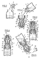
- Figures 1 through 3 show in cross-section the assembly of a packaging and dispensing system in accordance with the invention in a first embodiment with a bellows-like main body, figure 3 showing the product ready for use.
- Figure 4 is an axial cross-section showing the communication established by unscrewing for mixing prior to first use of the previous system and figure 5 shows it in use.
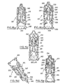
- Figures 6 through 8 show in cross-section the assembly of a system in accordance with the invention in a second embodiment where the cap is in three separable parts, figure 8 showing the product ready for use.
- Figure 9 is an axial cross-section showing the communication established by unscrewing, after separation of the parts forming the cap, before first use of the system shown in figure 8 and figure 10 shows it in use.
- Figures 11 and 12 respectively shown an exploded view and an axial cross-section in the assembled state of a third embodiment of the invention, the packaging and dispensing system comprising an intermediate bush providing a rotational drive coupling and a sliding member forming both a coupling to the plug and a dispensing nozzle.
- Figure 13 shows a detail of figure 12 in cross-section, showing the snap-action interaction between the cap and the bush, the arrow showing the direction for unscrewing the cap.
- Figure 14 is a partial view showing the base of the intermediate bush in two parts (not yet separated) used in the system shown in figures 11 and 12.
- Figures 15a through 15e respectively show the packaging and dispensing system of figures 11 and 12 ready for use, during mixing, at the time of opening, in use and reclosed after use.
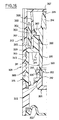
- Figure 16 is a half-view in axial cross-section showing a fourth embodiment of the invention, the packaging and dispensing system comprising a sliding latch and a cap with resilient drive and locking lugs.
- Figures 17 and 18 are half-views in axial cross-section showing a fifth embodiment of the invention, the packaging and dispensing system comprising a sliding latch, a cap with resilient drive and locking lugs and a coupling to the plug for improved extraction of the latter, the difference between the two figures relating to the material of the lower bottle, which is of glass in figure 18 whereas in figure 17 the bottle is a part of the plastics material body.
- Figures 19a through 19f show the packaging and dispensing system from figure 17 ready for use, during mixing (before and after disengagement of the resilient lugs from the cap), after removal of the cap for opening, in use and reclosed after use.
- Figures 20 and 21 are half-views in axial cross-section showing a sixth embodiment of the invention, the packaging and dispensing system resembling that of figures 17 and 18 but without any sliding latch and with a double screwthread on the resilient lugs of the screwcap, the plug being once again extracted by rotation and the lower bottle in figure 1 being of glass, whereas in figure 20 it is a part of the plastics material body.
- Figures 22 and 23 are respectively cross-sections on the lines XXII-XXII and XXIII-XXIII in figures 20 and 21 showing the respective rotational couplings.
- Figure 24 is a half-view in perspective showing the construction of the plug in the fifth and sixth embodiment systems, with double rotational coupling.
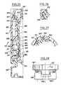
- Figure 25 is a half-view in axial cross-section showing a seventh embodiment of the invention, the packaging and dispensing system being suited to the use of a screwcap and comprising a bush with a disposable snap-action ring to prevent the plug being screwed back in on closing after use.
- Figure 26 is a cross-section on the line XXVI-XXVI in figure 25 showing the coupling at the level of the plug.
- Figure 27 is analogous to figure 13 and shows the snap-action interaction of the cap and bush in the system shown in figure 25, the arrow showing the direction for unscrewing the cap.
- Figure 28 is analogous to figure 14 and shows the two parts of the previously mentioned intermediate bush, where in this instance the upper part is disposable.
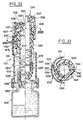
- Figure 29 is an axial cross-section showing an eighth embodiment of the invention (the lefthand half-section corresponds to the packaging and the righthand half-section corresponds to the opening of the system, the cap being unscrewed from the main body of said system), the packaging and dispensing system comprising a sliding member with retractable spring lugs onto which the cap screws.
- Figure 30 is a cross-section on the line XXX-XXX in figure 29 showing the snap-fastener connection between the lugs on the sliding member and the screwcap for two different unscrewing positions of said cap.
- Figure 31 is a cross-section on the line XXXI-XXXI in figure 29 analogous to figure 23.
- Figure 32 is an axial cross-section showing a ninth embodiment of the invention in which the packaging and dispensing system comprises (as in the previous embodiment) a sliding member with retractable spring lugs onto which the cap screws with in this instance a dispensing nozzle comprising a plug adapted to be pierced by a syringe (the lefthand half-section corresponds to the packaging and the righthand half-section corresponds to opening of the system, the cap having been removed to provide access to the plug which can then be pierced by a syringe).
- Figure 33 is a cross-section on the line XXXIII-XXXIII in figure 32 showing a snap-fastener connection analogous to that of figure 30.
- Figures 1 through 3 show the assembly of a packaging and dispensing system of a first embodiment of the invention, figure 3 showing the product ready for use.
- The packaging and dispensing system shown in figure 3 comprises a
first bottle 2 containing thefirst ingredient 3, which is a liquid or a solid, the neck 4 of said bottle being closed by aplug 5. Theplug 5 has a special construction in the context of the invention, in the sense that it comprises amain plug part 6 featuring acentral orifice 7 and a clip-on or snap-onobturator part 8 implementing the plugging function proper. Thispart 8 features an outwardly facingrecess 8′ whose shape is adapted to form a coupling with an internal coupling member carried by the second bottle as will be described hereinafter. The system comprises a second bottle 9 (the construction of which will be described in more detail later) containing the second,liquid ingredient 10. The second bottle is attached to thefirst bottle 2 at its neck. - The
system 1 comprises aninternal coupling member 11 carried by thesecond bottle 9, said member being of elongate shape and having anend 12 coupled to theplug 5 which closes off thefirst bottle 2, the coupling being effected automatically when fitting said first and second bottles together. - The system comprises a
cap 13 screwed onto thesecond bottle 9, said cap being joined to theinternal coupling member 11 in such a way that on first use unscrewing of said cap first displaces theplug 5 and so establishes automatically the communication between the first andsecond bottles nozzle 14 carried by said second bottle. - In the context of the first embodiment shown in figures 1 through 5, the
second bottle 9 of the packaging and dispensing system comprises a bellows-likemain body 15 which has oneend 16 adapted for fastening to thefirst bottle 12. Theother end 17 has ascrewthread 18 on the outside and carries theinternal coupling member 11 on the inside. Thecoupling member 11 comprises in this instance a fixingring 19 which is received into a groove inside theend 17 of themain body 15, said ring being extended by arod 20 theend 12 of which provides the coupling to theplug 5. The shapes of theend 12 of the coupling member and of therecess 8′ in theplug 5, in combination with the resilience of said plug, are adapted to securing an automatic snap-action fastening on penetration of saidend 12, in the manner of a harpoon. - The
second bottle 9 further comprises a sleeve forming acap 13 and surrounding the bellows-likemain body 15. Oneend 21 of thesleeve 13 is rotatably mounted on theassembly end 16 of the bellows-likemain body 15 while its other end has ascrewthread 22 on the inside cooperating with theexternal screwthread 18 on the main body so that communication between the first andsecond bottles sleeve 13 relative to said first bottle. It will be seen that the threaded end of themain body 15 is extended by a portion receiving the dispensingnozzle 14, said portion carrying aclosing capsule 24, in this instance screwthreaded, this capsule being integrated into the end of thesleeve 13 until such time as communication has been established between the first andsecond bottles - The
sleeve 13 has in its central part at least one (in this instance two)lateral windows 24 enabling the bellows to be compressed during dispensing. It is advantageous for theend 21 of thesleeve 13, mounted on theassembly end 16 of the main body, to terminate in aprotection ring 25 coupled to said assembly end. The presence of a centeringring 26 fastened to therod 20 of thecoupling member 11 will also be noted. - To obtain the packaging and dispensing system shown in figure 3, the procedure is as follows: the ingredient 3 (liquid, powder, freeze-dried ingredient) having been placed in the
first bottle 2, this bottle is stoppered with theplug 5, as schematically shown in figure 1. The approriate quantity of theother ingredient 10, which is a liquid, is then placed in thesecond bottle 9 turned upside down with its dispensing nozzle facing downwards and its cap screwed on, as shown in figure 2; thefirst bottle 2 is then brought above thesecond bottle 9 and the two bottles are then fastened together, which automatically secures the coupling between theend 12 of the coupling member and theremovable portion 8 of theplug 5. The packaging and dispensing system obtained in this way can be stored, each of the ingredients being safely confined in its own bottle. It should be noted that in the case of a freeze-dried ingredient thesecond bottle 2 will be made from glass, the flexibility needed for dispensing being achieved by flexible implementation of the bellows-like main body. - It is important to note that the packaged system as shown in figure 3 does not provide any access to the
capsule 23, which is integrated into the screwcap. - At the time of first use, the sleeve forming the
cap 13 is first turned in the normal unscrewing direction, the first effect of which is to break off the separation in theprotection ring 25; then, by virtue of cooperation between the screwthreads 18 and 22, theend 17 of the main body moves upwards relative to thesleeve 13 as far as an abutment position. This movement automatically entrains thepart 8 of the plug, and so establishes the communication between the two bottles, which enables the two ingredients to be mixed. It is only at this stage that theclosure capsule 23 is accessible to the user, who need only unscrew this capsule to use the mixture. Figure 5 is a schematic illustration of such use, after removal of theclosure capsule 23. - Thus, with a packaging and dispensing system of this kind, it is impossible to use one of the two ingredients in the non-mixed state. Also, further use after screwing on the
closure capsule 23 is possible only if this capsule is accessible: thus if the user should erroneously maneuver thecap 13 the capsule will no longer be accessible, with the result that it is impossible to re-partition the two chambers on subsequent use. Finally, the presence of a protection ring provides a visible record of the first opening of the system. - Figures 6 through 10 show a second embodiment of the packaging and dispensing system in accordance with the invention. In this embodiment the main body of the second bottle is no longer of the bellows type and the cap has a special construction in three separable parts.
- For reasons of clarity, the component parts of the system in this second embodiment with counterparts in the previous embodiment carry the same reference numbers increased by 100.
- Thus there are seen in figure 6 a
first bottle 102 containing aningredient 103 and theneck 104 of which is stoppered by aplug 105. Note that in this instance theplug 105 is in one piece and that its upper portion features arecess 108′ (figure 7) for coupling to an internal coupling member, harpoon-fashion and as explained with reference to the previous embodiment. In this case themain body 115 is essentially cylindrical and itslower end 116 is adapted for assembly to thefirst bottle 102, while its other end carries a dispensingnozzle 114. Differing in this respect from the previous embodiment, the dispensingnozzle 114 is in the form of a hollow body which itself supports thecoupling member 111. The dispensingnozzle 114 is received into themain body 115 by virtue of a splined coupling permitting telescopic motion of said nozzle: there arerespective splines nozzle 114 and internally on themain body 115. The dispensingnozzle 114 can thus be moved between a low position shown in figure 8 and a high position shown in figures 9 and 10, in which position said nozzle is held by abutments 132 (abutment members) and 133 (a lip at the end of the main body 115). Thecoupling member 111 comprises a fixingring 119 received into a groove or a bore inside the dispensingnozzle 114, said ring being extended as previously by arod 120 theend 112 of which provides the coupling to theplug 105. - In the context of this second embodiment, the
second bottle 109 comprises acap 113 formed of threeseparable parts part 127 is rotatably mounted on said body, with twointermediate ramps lower part 127 of thecap 113 is thus fixed to but can rotate on themain body 115. Theparts ramp 130, while theparts ramp 131 in the opposite direction, the lastseparable part 129 featuring a threadedsleeve 136 which screws onto the dispensing end of thenozzle 114 to close off theorifice 135 of the latter. - The
system 101 is assembled in a similar way to the previous embodiment: first the required quantity of theingredient 103 is placed in the first bottle 102 (figure 6), which is then stoppered in a fluid-tight manner with theplug 105. The required quantity of the other, liquid ingredient is then placed in thesecond bottle 109, while it is upside down with its dispensing nozzle facing downwards and its cap screwed on, as shown in figure 7. Thefirst bottle 102 is then assembled to thesecond bottle 109 by simply clipping theend 116 of thebody 115 onto theneck 104 of thefirst bottle 102, which simultaneously and automatically provides the coupling between theend 112 of thecoupling member 111 and theplug 105. - At the time of use, the user unscrews the
cap 113, holding itsupper part 129. This unscrewing motion first leads to separation of theparts ramp 130, the remaining parts of the cap move upwards, entraining not only the dispensingnozzle 114 but also thecoupling member 111 which removes the stopper and, by establishing the communication between the two bottles, makes it possible to mix the two ingredients. At the end of telescopic sliding movement of thenozzle 114, the latter is held between theabutments parts part 128 then remains on themain body 115 whereas the lastseparable part 129 then constitutes an ordinary cap for the resulting assembly. The splined coupling between the nozzle and the main body means that unscrewing of thelast part 129 makes it a simple matter to uncover theorifice 135 in the dispensing nozzle. Once the lastseparable part 129 has been removed, the packaging and dispensing system is in the condition shown in figure 9. Droplets may then be easily administered, for example by manual compression of themain body 115, as shown in figure 10. When the user screws on theseparable part 129 forming a cap, the effect of theupper ramp 131 is to push down theintermediate part 128 if still in the high position, so preventing any further downward telescopic movement of the dispensingnozzle 114. This ensures that it is impossible to re-partition the two chambers after the system has been opened. - As compared with the previous embodiment, this
second embodiment 101 has the advantages of greater simplicity and a reduced number of parts. Also, the user has only one member to maneuver (theupper part 129 of the screwcap). The further embodiments of the invention that are now to be described concern packaging and dispensing systems in which the second bottle comprises on the one hand a main body of which one end receives by virtue of telescopic sliding movement a member constituting both the internal coupling member and the dispensing nozzle and, on the other hand, a cap screwed onto the main body and comprising a direct or indirect drive linkage with the sliding part: thus, in the context of such embodiments, unscrewing of the cap results automatically in displacement of the single sliding part to establish the communication between the first and second bottles before uncovering the orifice in the dispensing nozzle, the structure being such that screwing the cap on again cannot result in reverse displacement of said sliding part. - Figures 11 through 14 show a third embodiment of the invention, with a packaging and dispensing system comprising an intermediate bush providing a rotational drive linkage and a sliding part providing both the coupling to the plug and the dispensing nozzle.
- Thus there are seen in figures 11 and 12 a
first bottle 202, in this instance withexternal splines 240 on its neck, said bottle being stoppered in a fluid-tight way by aplug 205 which is in this instance surmounted by four hook-shape members 241 for coupling it to the slidingmember 211 which forms, as explained above, both the coupling member for the coupling to the plug and the dispensing nozzle. Themain body 215 receives the slidingmember 211 by virtue of a splined coupling permitting telescopic motion, in a similar way to the coupling provided in the previously shown embodiment: there are thusexternal splines 237 on the slidingmember 211 andinternal splines 238 on themain body 215. Upward movement of the slidingmember 211 is limited by the inwardly projectingrim 233 at the end of themain body 215. The slidingmember 211 further features aradial flange 250 external to themain body 215 and surmounted by the dispensingnozzle 214. - In this third embodiment there is provision for disposing an
intermediate bush 245 around the end of themain body 215 and adjacent theradial flange 250 on the slidingmember 211. Thisintermediate bush 245 is designed to be entrained directly by thecap 213 when the latter is unscrewed, in order to serve as a lifting device procuring upward movement of the slidingmember 211. As seen from figures 11, 12 and 14, theintermediate bush 245 is in twoseparate parts 246, 247: thepart 247 is a snap-action ring which is smooth on the inside and thepart 246 is a sleeve which is threaded on the inside, said parts being constrained to rotate together when in contact with each other. This is achieved by cooperation betweenprojections 248 on thering 247 andcorresponding notches 249 in thesleeve 246. In practise, as shown in figure 14, thebush 245 may be made by injection molding, after which the twoportions points 248′ and 248˝, which linkages are broken at assembly time when the bush is compressed longitudinally. The snap-action ring 247 hasteeth 247′ cooperating withcorresponding notches 254 on the inside of the cap 213: it should be noted that the entrainment is effective in the direction of unscrewing thecap 213, which direction is shown by thearrow 200 in figure 13 and 14 showing the details concerned. - Thus the
main body 215 has two essentiallycoaxial screwthreads internal thread 253 on thecap 213 and aninternal thread 256 on theintermediate bush 245. The presence of ashoulder 257 inside thecap 213, adjacent to thesplined area 254 which cooperates with the snap-action ring 247, should also be noted. This shoulder is an additional safety feature to ensure separation of the snap-action ring 247 from thesleeve 246 when thecap 213 is screwed on again. - Finally, the sliding
member 211 has, running from the side of theradial flange 250 opposite the dispensing nozzle, atubular part 220 whoseend 212 provides the coupling to theplug 205, said part preferably comprisingradial perforations 252 to increase its elasticity in the longitudinal direction. This spring effect is particularly beneficial for ensuring a good seal in the axial direction at theplug 205. Thetubular part 220 also comprises aradial orifice 251 for the liquid to pass through towards the orifice in the end of the nozzle. It will be noted in particular that the slidingmember 211 features a slightlyconical bore 258 to ensure that no drops of liquid can be held back by capillary action and thus escape mixing, any such drop always falling back to ensure correct mixing of the two ingredients. It should also be noted that thesplines member 211 on unplugging causes a drop in pressure which increases the internal volume of the chamber, this drop in pressure causing air to enter through the orifice and contributing also to the expelling of any droplet that may be retained in the central bore of said sliding member. - To assemble the packaging and dispensing
system 201, the first stage is to pre-assemble the second bottle 209: thus themain body 215, theintermediate bush 245, the slidingmember 211 and thecap 213 are fitted together. It should be noted that during screwing on of thecap 213 the snap-action coupling functions like a freewheel and therefore does not interfere at all with the complete screwing on of said cap, so ensuring that theorifice 235 of the dispensingnozzle 214 is correctly plugged and that theflange 250 on the sliding member bears correctly against therim 233 on themain body 215 to obtain a perfect seal. The assembly process is thereafter comparable in all respects with that already described for the previous embodiments: first the required quantity of one ingredient is placed in thefirst bottle 202 which is then plugged with aplug 205 shaped to enable subsequent coupling (in this instance, this plug will preferably be made of polyethylene or polypropylene); the required quantity of the other, liquid ingredient is then placed in thesecond bottle 209 held upside down with its dispensing nozzle facing downwards and its cap screwed on; finally, thebottles plug 205 within the system by virtue of snap-action engagement between theend 212 and thehooks 241 on theplug 205. - Figures 15a through 15e explain how a packaging and dispensing system of this kind is used:
- - Figure 15a: the
system 201 is ready for use, meaning that theingredients plug 205 and by thesplines 240 on thefirst bottle 202. - - Figure 15b: the user begins to unscrew the
cap 213, which entrains with it thering 247 and thesleeve 246; theintermediate bush 245 is therefore also entrained with an unscrewing motion (thescrewthreads intermediate bush 245 thus pushes up theflange 250, entraining in its telescopic motion the slidingmember 211 and therefore the plug 205: the communication between the two bottles is thus established and the mixing may proceed correctly. - - Figure 15c: the
intermediate bush 245 reaches an unthreaded part of themain body 215 and the slidingmember 211 abuts at the top end of its travel against the rim 233: thecap 213 therefore continues to move on its own as unscrewing proceeds and thering 247 will usually drop down to rest on themain body 215. - - Figure 15d: once the
screwcap 213 has been removed the system is open and ready for use, either by compressing the main body laterally or by pressing on the bottom of thefirst bottle 202. - - Figure 15e: the user then screws the
screwcap 213 back on: theshoulder 257 on said cap is then certain to push down thering 247, if this has not fallen down previously, which prevents any possible subsequent coupling between the thus separated bush and the screwcap, so that said cap serves in future as an ordinary cap, without any risk of re-partitioning the two chambers of thesystem 201. What is more, further teeth could be provided on the upper edge of thesleeve 246 and on the lower edge facing it of theflange 250 to enable relative rotation movement only in the unscrewing direction (such teeth have not been shown here to avoid overcomplicating the figures). - It should be noted that in the storage position (figure 15a) the sliding
member 211 forming a "harpoon" serves to retain the plug by exerting a constant closing force, which enhances the seal between the two bottles, and in particular prevents theplug 205 moving and accidentally establishing premature communication between the two chambers due to any impact or to any difference in pressure between the two chambers. Also, and as previously, if the packaging and dispensing system has been assembled under sterile conditions, the mixing operation is achieved without compromising such sterile conditions. - Figure 16 shows a fourth embodiment of the invention, with a packaging and dispensing
system 301 comprising a sliding latch and a cap with resilient drive and locking lugs. As will be explained subsequently, an embodiment of this kind can be adapted to permit extraction of the closure plug by turning it. - A
first bottle 302 is welded to amain body 315. The bottom 302′ may likewise be welded to the side wall of said bottle. Themain body 315 receives a slidingmember 311 through a coupling enabling free telescopic movement in rotation and in translation, differing in this from the previous embodiments in which a splined coupling was provided. Thus themain body 315 has a singleexternal screwthread 343 cooperating with theinternal thread 353 on ascrewcap 313. Beyond this is ashoulder 359 surmounted by a portion forming asmooth sleeve 360 which terminates in a projectingrim 361. - Below the dispensing
nozzle 314 the slidingmember 311 features ashoulder 362 provided withexternal splines 363. Themain body 315 also carries alatch 364 in the form of a sliding sleeve which can move longitudinally over a predetermined distance. Thelatch 364 is preferably a smooth sleeve and features aninternal shoulder 365 adapted to cooperate with the projectingrim 361 on themain body 315 in the position in which said latch is extended to the maximum extent. - The
screwcap 313 has resilient lugs 366 (of which there are four, in a tulip-like configuration), these lugs passing being inserted (while prestressed in bending) between thelatch 364 and theshoulder 362 on the slidingmember 311. The free end of eachresilient lug 366 is toothed to cooperate with thesplines 363 on the shoulder, so creating a rotational coupling (which is temporary, as will be explained later) between thescrewcap 313 and the slidingmember 311. The slidingmember 311 is extended at the lower end by atubular part 320 whoseend 312 provides the coupling to theplug 305, said tubular part comprising, as previously,radial perforations 352 to increase its elasticity in the longitudinal direction. - In the ready for use condition shown in figure 16, the
orifice 335 in the dispensingnozzle 314 is closed off by the top 367 of thescrewcap 313. When the user begins to unscrew thecap 313 the coupling through theresilient lugs 366 causes the slidingmember 313 to turn also, provided that the latch 264 continues to hold said lugs prestressed in bending. Because of this, the upward movement of thecap 313 is accompanied by simultaneous upward movement of thelatch 364 and of the slidingmember 311 forming a "harpoon": as previously, the upward movement of the slidingmember 311 unstops thefirst bottle 312 and establishes the communication between the two chambers for correct mixing of the two ingredients. At the end of an initial travel the latch butts up against the main body, when it contacts therim 361 of said body: because of this, further unscrewing of thecap 313 gradually releases theresilient lugs 366 from the latch until the ends of said lugs pass beyond theedge 368 which defines the latching limit and the end of the second travel. Immediately theresilient lugs 366 are released from thelatch 364, they move apart of their own accord because of their inherent elasticity, which prevents any subsequent insertion of said lugs between the latch and the sliding member when the cap is screwed on again. Nevertheless, it is preferable to provide also a direct latching action between the slidingmember 311 and themain body 315 in order to prevent with absolute certainty any subsequent downward movement of the plug 305: this is achieved by providing coupling means 370, 371 between the main body and the plug, said means operating automatically in the position with the slidingmember 311 extended to the maximum extent. Thus there is seen in figure 16 anextension 305′ of theplug 305 withexternal projections 370 that can cooperate with a plurality ofhooks 371 formed on themain body 315. - It is also beneficial to have the coupling between the end of the sliding
member 311 and theplug 305 also provide for rotational locking, preferably by cooperation between splines andgrooves 369, so that said plug can be extracted by turning on unscrewing thecap 313. Figures 17 and 18 show a fifth embodiment of the invention differing slightly from the previous embodiment. The only significant difference between the packaging and dispensingsystems 401 of figure 17 and 501 of figure 18 is essentially concerned with the fact that, in the case of thesystem 401, the lower part of themain body 415 itself constitues thefirst bottle 402, the neck of said bottle being defined by aconstriction 404 of said body, whereas thebottle 502 of the system 501 is a glass bottle. The following description will therefore be limited to the system shown in figure 17, the system of figure 18 comprising analogous component parts with reference numbers in the 500 range. - The
main body 415 of thesystem 401 receives the slidingmember 411 through a screw coupling, said sliding member having acoaxial sleeve 476 threaded internally and cooperating with the externally threadedend 477 of said body. The main body may naturally be made in two separate parts by injection molding with said parts then welded together. Themain body 415 also carries alatch 464 in the form of a sliding sleeve that can move longitudinally over a predetermined travel. Thelatch 464 is similar to the latch of the previous embodiment, except that its structure is slightly modified to allow for the screw coupling between themain body 415 and the slidingmember 411. Thus thelatch 464 is a smooth sleeve having on the inside afirst latching shoulder 474 and on the outside asecond abutment shoulder 472 adapted to cooperate with a projectingrim 473 on themain body 415 in the position with said latch extended to the maximum extent. The presence on the edge of thecoaxial sleeve 476 ofsplines 475 adapted to cooperate with the toothed ends ofresilient lugs 466 analogous to the resilient lugs provided in the embodiment previously described will also be noted. Thescrewcap 413 haslugs 466 inserted, while prestressed in bending, between thelatch 464 and the edge of thesleeve 476 of the slidingmember 411. Thescrewcap 413 also has, projecting from its top 467, an internally threadedtubular portion 466 which screws on to the dispensingnozzle 414. - As previously, the coupling between the end of the sliding
member 411 and theplug 405 also provides rotational locking, preferably by virtue of cooperation between splines andgrooves 469, so that said plug can be extracted by turning on unscrewing thecap 413. - Differing in this from the previous embodiment with snap-action hooks, the
system 401 comprises additional rotational coupling means 479, 480 operating automatically in the position with the slidingmember 411 extended to the maximum extent to enable normal unscrewing of the cap in use; these additional rotational coupling means comprise on the one hand longitudinalresilient lugs 478 attached to themain body 415 with their end toothed on the inside and, on the other hand, snap-action teeth 480 provided at the periphery of theplug 405, said means securing coupling between said body and said plug only in the direction of unscrewing the cap 413 (this snap-action mode will be described subsequently with reference to figures 23 and 24 corresponding to thesystems - As previously, the sliding
member 411 features, running from itssleeve 476 on the side opposite the dispensingnozzle 414, atubular part 420 whoseend 412 provides the coupling to theplug 405, said part comprisingradial perforations 452 to increase its elasticity in the longitudinal direction. - The advantageous presence of
fins 405˝ in the lower part of thecap 405 to facilitate the passage of water vapor in the case of a freeze-dried ingredient will also be noted. - Figures 19a through 19f show the various stages of use of the packaging and dispensing
system 401 from figure 17, as briefly described hereinbelow. - - Figure 19a: the
system 401 is in the ready for use condition shown in detail in figure 17. In this condition, each of theingredients plug 405, on which themember 411 forming a "harpoon" presses, providing a perfect seal between the two chambers. - - Figure 19b: when the user begins to unscrew the
cap 413, it entrains in the upward direction themember 411 together with thelatch 464, until the latter is stopped at the upper end of its movement by contact with therims resilient lugs 466 from thelatch 464, so eliminating the rotational drive coupling to themember 411. As previously, the upward movement of themember 411 has drawn theplug 405 with it and so established the communication between the two chambers for mixing of the two ingredients. - - Figure 19c: the resilient lugs are now free of the
latch 464 and have returned to their natural position. Also, the coupling at the lower part of themember 411 is already operative due to the action of theresilient lugs 478, so that it is not possible to screw themember 411 down again. - - Figure 19d: the
cap 413 is now totally unscrewed, providing access to the dispensingnozzle 414. In theory, thelatch 464 has dropped down due to its own weight: in any event, it can no longer be operative once thecap 413 has been unscrewed for the first use. - - Figure 19e: the system is used to dispense droplets of the mixture through the
orifice 435, either by pressing on the side walls of themain body 415 or by pressing on the bottom of the part of said body forming thebottle 401. - - Figure 19f: the user then screws the
cap 413 back onto the nozzle 414: at the end of its travel, the torque exerted on it can no longer screw down themember 411 because of the coupling provided by theresilient lugs 478, so that the communication between the two chambers is continuously established from this time onwards. - Figures 20 and 21 show a sixth embodiment of the invention, with a packaging and dispensing system similar to those of figures 17 and 18 but without any sliding latch and with a double screwthread on the resilient lugs of the screwcap. As in the preceding embodiments, means are advantageously provided to enable the plug to be extracted by turning.
- As in figures 17 and 18, the packaging and dispensing
systems bottle 602, 702: for thesystem 601 the lower part of themain body 615 itself constitutes thefirst bottle 602, the neck of said bottle being defined by aconstriction 604 of said body, whereas thebottle 702 of thesystem 701 is separate and made of glass. As the other component parts are identical, the description will be limited to thesystem 601, corresponding component parts of thesystem 701 having reference numbers in the 700 range. - The
main body 615 receives the slidingmember 611 through a screw coupling, said sliding member featuring an internally threadedcoaxial sleeve 676 cooperating with an externally threadedfirst end 677 of said body, which has an internally threadedsecond end 681 facing towards said first end and cooperating with theresilient lugs 666 of acap 613 which are externally threaded. In this embodiment the function of the latch in the previous embodiment is thus implemented by the main body itself. - The
resilient lugs 666 of thescrewcap 613 surround thesleeve 676 of the slidingmember 611 and hold thecapsule 623 associated with the dispensingnozzle 614 for as long as its thread is engaged with that on themain body 615, after which said cap can be disposed of and said capsule serves as an ordinary cap. Thescrewcap 613 and the slidingmember 611 are rotationally coupled, preferably by cooperation of splines and grooves, for as long as the thread on said cap is meshed with that on themain body 615. Figure 22 is a cross-section showing the rotational coupling between theresilient lugs 666 and the threadedsleeve 676 of the slidingmember 611. - In the lower part of the sliding
member 611 forming a "harpoon" there is a rotational coupling similar to that already described for thesystems 401 and 501 of figures 17 and 18. Thus there is a coupling between theend 612 of the sliding member and theplug 605 which also secures rotational locking, preferably as a result of cooperation between splines and grooves, so that the plug can be withdrawn by turning on unscrewing thecap 613. There are also additional rotational coupling means between themain body 615 and theplug 605, said means operating automatically in the position with the slidingmember 611 extended to the maximum extent to enable normal unscrewing of thecapsule 623 in use: these additional rotational coupling means comprise on the one hand longitudinalresilient lugs 678 attached to themain body 615 with the end toothed internally and, on the other hand, snap-action teeth 680 formed at the periphery of theplug 605, said means providing a coupling only in the direction of unscrewing thecap 613 or thecapsule 623. These couplings are seen more clearly on referring to the cross-section in figure 23, where it is possible to distinguish between an internal coupling through cooperation between splines and grooves between theend 612 and theupper part 605′ of theplug 605 and an external snap-action coupling between said plug and theresilient lugs 678 attached to themain body 615. - For a better understanding of the precise structure of the
plug 605, reference should be had to figure 24 which shows clearly theinternal splines 669 and the external snap-action teeth 680. There is also seen acentral protuberance 605‴ projecting axially upwards, this protruberance preventing any retention of isolated droplets in a dead area which could as a result be dispensed from the dispensing system in the non-mixed condition. - When the user begins to unscrew the
cap 613 the slidingmember 611 is entrained by cooperation between theresilient lugs 666 of said cap which continue to be held against thesleeve 676 by virtue of the thread on theend 681 of the main body. This unscrewing movement causes the slidingmember 611 to move upwards and, as in the previous embodiments, raising and rotation of theplug 605, to establish the communication between the two bottle chambers and mixing of the two ingredients. It should be noted that during this partial unscrewing of thecap 613 the user does not as yet have any access to thescrew capsule 623 which closes off the dispensingnozzle 614. As unscrewing of thecap 613 continues, the outside thread on theresilient lugs 666 is no longer meshed with that of theend 681 with the result that thecap 613 can slide upwards and so be disposed of. The user then has merely to maneuver thecapsule 623 to use the mixture, just like an ordinary cap. It goes without saying that the snap-action coupling provided at the level of the plug prevents any subsequent screwing down of the slidingmember 611 when the user screws thecapsule 623 back on after use. Theembodiments small diameter capsule 623; this significantly reduces the risk of the anti-unscrewing teeth being damaged. Also, the fact that the screwcap is disposable enables the user to shake the system for optimum mixing before opening for first use. Also, the sealing of the packaging and dispensing system is totally satisfactory in that, during storage, there are three seals between the slidingmember 611 and the body 615 (two seals in the radial direction at the level of the outside wall of thetubular part 620 and one seal in the axial direction at the level of the top of the threaded end 677) and in that, during use, there are two seals, namely the two radial seals just mentioned. - As in the previous embodiments, the sliding
member 611 has atubular part 620 comprisingradial perforations 652 to increase its elasticity in the longitudinal direction, so that it can contribute to obtaining a perfect seal within the system. - Figure 25 shows a seventh embodiment of the invention, with a packaging and dispensing
system 801 suited to the use of a screwed plug and comprising a bush with a disposable snap-action ring to prevent the plug being screwed in again on reclosing after use. - Thus the
second bottle 809 comprises amain body 815 of which one end can be assembled to thefirst bottle 802 and the other end receives thecoupling member 811 by virtue of a screw coupling. Unlike the previous screw coupling embodiments, in this instance thecoupling member 811 comprises an externally threadedcentral part 882 extended by an externallysmooth part 883 closed off by a dispensingnozzle 814, which in this instance is not integral with it. Themain body 815 comprises anupper extension 884 with a threaded lower part and a smooth upper part in corresponding relationship. - The
cap 813 screwed onto themain body 815 comprises a rotational drive linkage with anintermediate bush 845 extending thecoupling member 811. In the same way as theintermediate bush 245 previously described with reference to figures 11, 12 and 14, theintermediate bush 845 is in two separate parts, the first being adrive ring 846 attached to thecoupling member 811 and the second being a snap-action ring 847: theparts cap 813 is unscrewed for the first use, after which said snap-action ring is disposable. This rotational drive coupling is such that unscrewing thecap 813 automatically displaces thecoupling member 811 to establish the communication between the first andsecond bottles orifice 835 in the dispensingnozzle 814. Figure 28, which is analogous to figure 14, shows the intermediate bush as made by injection molding, with fragile linking points 848′ and 848˝ which are broken when the system is assembled; there is also aprotuberance 848 inserted into acorresponding recess 849, thearrow 200 showing the unscrewing direction. Figure 27, which is analogous to figure 13, likewise illustrates the snap-action coupling between thegrooves 854 on thescrewcap 813 and theteeth 847′ on the aforementioned snap-action ring 847. - Differing in this respect from the previous embodiments, the
plug 805 is here screwed onto thefirst bottle 852. Because of this, it is necessary to provide a coupling between theend 812 of thecoupling member 811 and theplug 805, which coupling also secures rotational locking, preferably as a result of cooperation between splines and grooves, so that said plug can be unplugged on unscrewing the cap 813: the detail cross-section in figure 26 shows a spline and groove coupling of this kind. Theplug 805 also features an internally projectingrim 887 which holds the plug once the latter has been withdrawn from the corresponding thread on thebottle 802. - As previously, additional rotational coupling means are provided between the
main body 815 and theplug 805, said means operating automatically in the position in which thecoupling member 811 is extended to the maximum extent. These additional means comprise on the one hand longitudinalresilient lugs 878 attached to themain body 815 and internally toothed at the end and, on the other hand, snap-action teeth 880 provided at the periphery of theplug 805, said means being operative only in the direction of unscrewing thecap 813. For a perfect understanding of these additional rotational coupling means reference should be had to figure 23. - When the user begins to unscrew the
cap 813 thecoupling member 811 is simultaneously entrained in rotation because of theintermediate bush 845. At the end of an initial travel, thebore 882 on thecoupling member 811 reaches the smooth part of theextension 884 of the main body 815: as a result, the upward movement of thecoupling member 811 ceases, whereas that of thecap 813 continues. In this position the threadedplug 805 has been unscrewed and communication between the two chambers has been established for mixing of the two ingredients. A projectinglug 885 may be provided on thetubular portion 820 of thecoupling member 811 to provide an abutment member in the raised position, bearing against ashoulder 886 on themain body 815. In the upper part theteeth 879 on thelugs 878 and theteeth 880 on theplug 805 are engaged with each other, preventing thecoupling member 811 being screwed in again at the time of subsequent replugging. Eventually thecap 813 is detached from the rest of the system, with the result that the snap-action ring 847 may be disposed of, preventing any possible entrainment in rotation during subsequent screwing or unscrewing of thecap 813. - Figures 29 through 31 show an eighth embodiment of the invention with a packaging and dispensing
system 901 resembling that 601 of figures 20, 22 and 23 except that it incorporates a sliding member with retractable spring lugs cooperating with the screwcap. - As previously the
system 901 comprises afirst bottle 902 with aneck 904 closed by aplug 905 and asecond bottle 909 assembled to thefirst bottle 902 at the neck of the latter (note in this instance, however, the presence of aclamping ring 988 made from aluminum, for example). Thesecond bottle 909 comprises amain body 915 receiving telescope-fashion a slidingmember 911 simultaneously forming the interior member of the coupling and the dispensing nozzle. - In this instance, however, the sliding
member 911 is screwed by means of an internallyscrewthreaded sleeve 976 onto theupper end 989 of the main body, which is screwthreaded externally, and thesleeve 976 comprises at least one (in this instance two) retractable spring lugs 990 which can "give" in the transverse direction. - The two
lugs 990 are joined to the sleeve proper by aligament 991 forming a hinge and are made in such a way that their natural position is a position corresponding to the lefthand half-section in figures 29 and 30. Each of the twolugs 990 has on its inside ascrewthread 990′ complementary to that of the sleeve (thescrewthread 990′ shown here therefore comprises two separate threads) and on the outside apeg 992 adapted to cooperate with internal teeth 993 (seen more clearly in figure 30) on thecap 913 which in this instance screws onto the sliding member 911: this makes it possible to define a snap-fastener connection between thescrewcap 913 and the slidingmember 911 which remains effective for as long as thescrewthread 990′ of eachspring lug 990 is engaged with that of theend 989 of themain body 915. - At the time of first use, the user begins to unscrew the
cap 913 which because of the aforementioned snap-fastener linkage entrains the slidingmember 911 and so establishes communication between the two bottles. - Immediately the
lugs 990 reach the upper edge of themain body 915 they retract because of the force exerted on them by the associatedpeg 992, which has two consequences: one is that the snap-fastener linkage between the cap and the sliding member is broken, so that subsequent screwing on of said cap cannot cause any retrograde movement of said sliding member, and the other is that this retracted position of the spring lugs simultaneously defines an abutment for axial movement in translation also preventing any retrograde movement of the sliding member. - It is beneficial for each
retractable spring lug 990 to have a projectingpoint 994 at the end. This point constitutes an additional safety feature designed to prevent "rescrewing" of the cap 913: when thelugs 990 are moved to their retracted position each of thepoints 994 cooperates with the adjacent interior screwthread on the sleeve 976 (as seen in the righthand half-section in figure 30) to lock the associated spring lug into its retracted position. This significantly improves the reliability of the axial translation abutment preventing any new movement of the slidingmember 911 inwardly relative to themain body 915. - In the lower part of the sliding
member 911 is an arrangement analogous to that already described for thesystem 601 with reference to figures 20 and 23. - There is therefore a rotational coupling by virtue of cooperation between splines and grooves between the
end 912 of the slidingmember 911 and theupper part 905′ of the plug 905 (the so-called internal coupling). There is also an additional rotational coupling between theplug 905 and themain body 915, in more precise terms in this instance between theupper part 905′ of the plug (by virtue of snap-fastener teeth 980) and the internally toothed end of longitudinal spring lugs 978. - However, in this instance the spring lugs 978 are slightly different from those of the systems previously described in that they feature a
shoulder 995 constituting an axial abutment for theplug 905 in the position of maximum extension of the slidingmember 911. - Also repeated from previous embodiments are
radial perforations 952 conferring greater longitudinal elasticity on the tubular part of the slidingmember 911. - Finally, and also as previously, the sliding
member 911 is surmounted by an externallyscrewthreaded dispensing nozzle 914 onto which thecap 913 screws by means of a tubularcentral portion 936 of the internally screwthreaded cap. - The principal advantages of this eighth embodiment lie in the absence of disposable parts (which avoids the patient experiencing any problem on reclosing the bottle, as the cap used to open it is employed for this), in the small number of component parts and in the high degree of security against "rescrewing" (relatively low protection against rotation supported in this instance by an axial translation abutment).
- Figures 32 and 33 show a ninth embodiment of the invention derived from the previous embodiment.
- The packaging and
dispensing system 1001 comprises as previously acap 1013 screwing onto a slidingmember 1011 with retractable spring lugs 1090 cooperating with said cap. - Identical or similar parts will not be described again, but simply assigned reference numbers increased by 100.
- The essential difference is found in the upper part of the device.
- The upper part of the sliding
member 1011 is closed by aplug 1014 which is adapted to be pierced by a syringe and which in this instance constitutes the dispensing nozzle and features above its internallyscrewthreaded sleeve 1076 anexternal screwthread 1096 onto which thecap 1013 screws, said cap having a closure bottom 1067 bearing againstpiercable plug 1014. - The piercable plug 1014 will generally be made from rubber or a suitable plastics material so that it can be readily pierced by the needle of a syringe.
- The arrangement show also makes it possible to preserve to the greatest possible extent the sealing and sterility characterics.
- The piercable plug 1014 is clamped between a
shoulder 1097 on the slidingmember 1011 and anannular boss 1098 projecting from the interior wall of theclosure bottom 1067. - Thus not only does the seal remain perfect but there is also an additional advantage with regard to sterility: the
annular boss 1098 delimits anarea 1099 which remains sterile until the first use of the packaging and dispensing system, located between the interior wall of theclosure bottom 1067 and the exterior wall of thepiercable plug 1014, so that the needle of the syringe enters an area which is protected until thescrewcap 1013 is opened for the operator to pierce theplug 1014. - It goes without saying that the invention is not limited to the various embodiments that have just been described, but to the contrary encompasses any variation thereon embodying, with equivalent means, the essential characteristics of the invention as defined in the appended claims.
Claims (45)
- a first bottle (2 ; 102 ; 202 ; 302 ; 402 ; 502 ; 602 ; 702 ; 802 ; 902 ; 1002) to contain the liquid or solid first ingredient and a plug (5, 8 ; 105 ; 205 ; 305 ; 405 ; 505 ; 605 ; 705 ; 805 ; 905 ; 1005) to close the neck of said first bottle;
- a second bottle (9 ; 109 ; 209 ; 309 ; 409 ; 509 ; 609 ; 709 ; 809 ; 909 ; 1009) to contain the liquid second ingredient adapted to be assembled to said first bottle (2 ; 102 ; 202 ; 302 ; 402 ; 502 ; 602 ; 702 ; 802 ; 902 ; 1002) at its neck;
- an internal coupling member (11 ; 111 ; 211 ; 311 ; 411 ; 511 ; 611 ; 711 ; 811 ; 911 ; 1011) carried by said second bottle (9 ; 109; 209 ; 309 ; 409 ; 509 ; 609 ; 709 ; 809 ; 909 ; 1009) of elongate shape and having one end adapted to be coupled automatically to said plug (5, 8 ; 105 ; 205 ; 305 ; 405 ; 505 ; 605 ; 705 ; 805 ; 905 ; 1005) closing said first bottle (2 ; 102 ; 202 ; 302 ; 402 ; 502 ; 602 ; 702 ; 802 ; 902 ; 1002) when said first and second bottles are assembled together;
- a dispensing nozzle (14 ; 114 ; 214 ; 314 ; 414 ; 514 ; 614 ; 714 ; 814 ; 914 ; 1014) carried by said second bottle; and
- a cap (13 ; 113 ; 213 ; 313 ; 413 ; 513 ; 613 ; 713 ; 813 ; 913 ; 1013) screwed onto said second bottle (9 ; 109 ; 209 ; 309 ; 409 ; 509 ; 609 ; 709 ; 809 ; 909 ; 1009) and coupled to said internal coupling member (11 ; 111 ; 211 ; 311 ; 411 ; 511 ; 611 ; 711 ; 811 ; 911 ; 1011) in such a way that on said first use unscrewing said cap initially displaces said plug 8 ; 105 ; 205 ; 305 ; 405 ; 505 ; 605 ; 705 ; 805 ; 905 ; 1005) and so automatically establishes the communication between said first and second bottles to enable safe mixing without prejudice to sterile conditions and subsequently uncovers said dispensing nozzle (14 ; 114 ; 214 ; 314 ; 414 ; 514 ; 614 ; 714 ; 814 ; 914 ; 1014).
- a bellows-like main body (15) one end of which is adapted to enable assembly to said first bottle (2) and the other end of which has a screwthread (18) on the outside and a coupling member (11) on the inside; and
- a sleeve forming a cap (13) surrounding the bellows-like main body (15), one end (21) of which is rotatably mounted on said assembly end (16) of said body and the other end of which has a thread (22) on the inside cooperating with said external thread (18) on said body, whereby communication between said first and second bottles (2, 9) is established automatically on rotating said sleeve relative to said first bottle.
- a substantially cylindrical main body (115), one end of which is adapted to be assembled to said first bottle and the other end of which carries a dispensing nozzle (114) through a splined coupling enabling telescopic movement of said nozzle, said nozzle carrying internally said coupling member 111; and
- a cap (113) mounted on said main body and comprising three separable parts (127, 128, 129) of which one part (127) is rotatably mounted on said body, with two intermediate ramps (130, 131) between said separable parts, said cap having an internal thread cooperating with an external thread on said dispensing nozzle (114) so that by turning said cap (113) relative to said main body (115) said dispensing nozzle (114) is moved to establish said communication between said first and second bottles (102, 109) before uncovering said orifice in said dispensing nozzle (114) by unscrewing the last separable part (129) which is by then detached from the others (127, 128).
- a main body (215 ; 315 ; 415 ; 515 ; 615 ; 715) one end of which is adapted to be assembled to said first bottle (202 ; 302 ; 402 ; 502 ; 602 ; 702) and the other end of which receives a telescopically sliding member (211 ; 311 ; 411 ; 511 ; 611 ; 711) constituting simultaneously said coupling member and said dispensing nozzle; and
- a cap (213 ; 313 ; 413 ; 513 ; 613 ; 713) screwed onto said main body and comprising a direct or indirect drive coupling with said sliding member (211 ; 311 ; 411 ; 511 ; 611 ; 711) so that unscrewing said cap results automatically in displacement of said sliding member to establish said communication between said first and second bottles before uncovering said orifice in said dispensing nozzle, said coupling being such that screwing said cap 213 ; 313 ; 413 ; 513 ; 613 ; 713) back on cannot cause displacement of said sliding member in the reverse direction.
- said main body (315) receives said sliding member (311) through a coupling enabling free telescopic movement in rotation and in translation, said member comprising a splined shoulder (362) external to said body, said main body (315) also carrying a latch (364) in the form of a sliding sleeve able to move longitudinally over a predetermined travel;
- said screwcap (313) comprises resilient lugs (366) inserted while prestressed in bending between said latch (364) and said shoulder (362) of said sliding member (311), the free end of said lugs being toothed to cooperate with said splines of said shoulder so that unscrewing said cap (313) initially entrains said latch (364) and said sliding member (313) to establish said communication between said first and second bottles (302, 309) and then said sliding member (311) only on releasing said resilient lugs which move apart of their own accord; and
- attachment means (370, 371) provided between said main body (315) and said plug (305), said means being operative automatically in the position in which said sliding member (311) is extended to the maximum extent.
- said main body (415 ; 515) receives said sliding member (411 ; 511) through a screw coupling, said sliding member comprising a coaxial sleeve (476 ; 576) threaded on the inside cooperating with the externally threaded end (477 ; 577) of said body, said main body (415 ; 515) also carrying a latch (464 ; 564) in the form of a sliding sleeve able to move longitudinally over a predetermined travel;
- said screwcap (413 ; 513) comprises resilient lugs (466 ; 566) inserted while prestressed in bending between said latch (464 ; 564) and the edge of said sleeve (476 ; 576) of said sliding member (411 ; 511), the free end of said lugs being toothed to cooperate with splines (475 ; 575) provided on said edge of said sleeve, so that unscrewing said cap (413 ; 513) initially entrains said latch (464 ; 564) and said sliding member (411 ; 511) to establish said communication between said first and second bottles (402, 409 ; 502 ; 509) and then said sliding member (411 ; 511) only on releasing said resilient lugs which move apart of their own accord;
- said screwcap (413 ; 513) further comprises a tubular central portion (436 ; 536) screwthreaded on the inside and screwed onto an external screwthread on said dispensing nozzle (414 ; 514);
- said coupling between said end of said sliding member (411 ; 511) and said plug (404 ; 505) also provides rotational locking, optionally by cooperation between splines and grooves, so that said plug is extracted by turning on unscrewing said cap (413 ; 513); and
- additional rotational coupling means (479, 480 ; 579, 580) are provided between said main body (415 ; 515) and said plug (405 ; 505), said means being operative automatically in the position with said sliding member extended to the maximum extent to enable normal unscrewing of said cap (413 ; 513) in use.
- said main body (615 ; 715) receives said sliding member (611 ; 711) through a screw coupling, said sliding member comprising an internally threaded coaxial sleeve (676 ; 776) cooperating with an externally threaded first end (677 ; 777) of said body, said main body (615 ; 715) having an internally threaded second end (681 ; 781) facing towards said first end and cooperating with resilient lugs (666 ; 766) on an externally threaded cap (613 ; 713);
- said resilient lugs (666 ; 766) of said screwcap (613 ; 713) surround said sleeve (676 ; 776) of said sliding member (611 ; 711) and hold an optionally screwthreaded closure capsule (623 ; 723) associated with said dispensing nozzle when its thread is meshed with that of said main body (615 ; 715), after which said cap is disposable and said capsule serves as an ordinary cap;
- said screwcap (613 ; 713) and said sliding member (611 ; 711) are rotationally coupled, optionally by cooperation of splines and grooves, while said thread of said cap is meshed with that of said main body (615 ; 715);
- said coupling between said end of said sliding member (612 ; 712) and said plug (605 ; 705) also provides rotational locking, optionally by cooperation of splines and grooves, so that said plug is extracted by turning on unscrewing said cap (613 ; 713); and
- additional rotational coupling means (679, 680 ; 779, 780) are provided between said main body (615 ; 715) and said plug (605 ; 705), said means being operative automatically in the position with said sliding member (611 ; 711) extended to the maximum extent to enable normal unscrewing of said capsule (623 ; 723) in use.
- a main body (815) one end of which is adapted to be assembled to said first bottle (802) and the other end of which receives said coupling member (811) through a screw coupling, said coupling member comprising an externally threaded central part (882) for said coupling extended by an externally smooth part (883) closed off by said dispensing nozzle (814);
- a cap (813) screwed onto said main body (815) and comprising a rotational drive linkage with an intermediate bush (845) extending said coupling member, said intermediate bush being in two separate parts of which the first is a drive ring (846) attached to said coupling member (811) and the second is a snap-action ring (847), said parts being constrained to rotate together when in contact with each other, that is to say until said cap (813) is unscrewed at the time of said first use after which said snap-action ring is disposable, said coupling being such that unscrewing said cap (813) automatically results in displacement of said coupling member (811) to establish said communication between said first and second bottles (802, 809) before uncovering said orifice of said dispensing nozzle (814);
and wherein:
- said plug (805) is screwed onto said first bottle (802); and
- said coupling between said end (812) of said coupling member (811) and said plug (805) also provides rotational locking, optionally by cooperation of splines and grooves, so that said plug can be unscrewed on unscrewing said cap (813).
- a main body (905 ; 1005) with one end adapted to be assembled to said first bottle (902 ; 1002),
- a sliding member (911 ; 1011) adapted to be received telescope-fashion in the opposite end of said main body and forming both said internal coupling member and said dispensing nozzle,
- an internally screwthreaded sleeve (976 ; 1076) adapted to cooperate with said opposite end of said main body which is externally screwthreaded and by virtue of which said sliding member is screw-coupled,
- a cap (913 ; 1013) adapted to be screwed to said sliding member (911 ; 1011) and comprising internal teeth (993 ; 1093) and a direct drive coupling to said sliding member whereby unscrewing said cap automatically displaces said sliding member to establish communication between said first and second chambers before exposing said dispensing nozzle and whereby screwing said cap (913 ; 1013) on again cannot impart retrograde movement to said sliding member, and wherein said externally screwthreaded sleeve (976 ; 1076) of said sliding member (911 ; 1011) comprises at least one retractable spring lug (990 ; 1090) movable transversely and having on its interior a screwthread (990′ ; 1090′) complementary to that of said sleeve and on its exterior a peg (992 ; 1092) defining with said internal teeth (993 ; 1093) on said screwcap (913 1013) a snap-fastener coupling between said screwcap and said sliding member effective when said screwthread on said spring lug is engaged with that on the end of said main body so as to define in a retracted position an axial translation abutment preventing retrograde movement of said sliding member and direct drive by said snap-fastener coupling.
- depositing a required quantity of a liquid or solid first ingredient in said first bottle (2 ; 102 ; 202 ; 302 ; 402 ; 502 ; 602 ; 702 ; 802 ; 902 ; 1002);
- stopping said first bottle by means of said plug (5 ; 105 ; 205 ; 305 ; 405 ; 505 ; 605 ; 705 ; 805 ; 905 ; 1005);
- depositing a required quantity of a liquid second ingredient in said second bottle (9 ; 109 ; 209 ; 309 ; 409 ; 509 ; 609 ; 709 ; 809 ; 909 ; 1009) while it is upside down with said dispensing nozzle facing downwards and said cap screwed on; and
- assembling said first bottle to said second bottle, whereby said coupling of said internal coupling member (11 ; 111 ; 211 ; 311 ; 411 ; 511 ; 611 ; 711 ; 811 ; 911 ; 1011) to said plug is automatically procured.
Priority Applications (1)
| Application Number | Priority Date | Filing Date | Title |
|---|---|---|---|
| AT89400553T ATE74098T1 (en) | 1988-03-02 | 1989-02-28 | PACKAGING AND DISPENSING SYSTEM FOR PACKAGING TWO COMPONENTS SEPARATELY AND FOR IMMEDIATE MIXING UPON FIRST USE AND METHOD OF ASSEMBLING THE SYSTEM. |
Applications Claiming Priority (2)
| Application Number | Priority Date | Filing Date | Title |
|---|---|---|---|
| FR8802612 | 1988-03-02 | ||
| FR8802612A FR2628075B1 (en) | 1988-03-02 | 1988-03-02 | PACKAGING AND DISPENSING ASSEMBLY FOR SEPARATING TWO COMPONENTS SEPARATELY, AND MAKING THEIR EXTEMPORANEOUS MIXTURE ON THE FIRST USE, AND METHOD FOR MANUFACTURING SUCH AN ASSEMBLY |
Publications (2)
| Publication Number | Publication Date |
|---|---|
| EP0333541A1 true EP0333541A1 (en) | 1989-09-20 |
| EP0333541B1 EP0333541B1 (en) | 1992-03-25 |
Family
ID=9363818
Family Applications (1)
| Application Number | Title | Priority Date | Filing Date |
|---|---|---|---|
| EP89400553A Expired - Lifetime EP0333541B1 (en) | 1988-03-02 | 1989-02-28 | Packaging and dispensing system for packaging two ingredients separately and mixing them extemporaneously at the time of first use, and method of assembling same |
Country Status (11)
| Country | Link |
|---|---|
| US (1) | US4936446A (en) |
| EP (1) | EP0333541B1 (en) |
| JP (1) | JPH0634917B2 (en) |
| AT (1) | ATE74098T1 (en) |
| CA (1) | CA1328093C (en) |
| DE (1) | DE68901054D1 (en) |
| DK (1) | DK167862B1 (en) |
| ES (1) | ES2030983T3 (en) |
| FR (1) | FR2628075B1 (en) |
| GR (1) | GR3004158T3 (en) |
| NO (1) | NO890878L (en) |
Cited By (15)
| Publication number | Priority date | Publication date | Assignee | Title |
|---|---|---|---|---|
| EP0392609A1 (en) * | 1989-04-12 | 1990-10-17 | Eastman Kodak Company | Package for storing and remixing two materials |
| FR2666305A1 (en) * | 1990-09-05 | 1992-03-06 | Oreal | DEVICE FOR STORING SEPARATELY FROM AT LEAST TWO PRODUCTS AND FOR MAKING THEIR MIXTURE AT THE TIME OF USE. |
| DE4323841C1 (en) * | 1993-07-16 | 1994-08-25 | Goldwell Ag | Twin-chamber container |
| EP0810164A1 (en) * | 1996-05-30 | 1997-12-03 | Jürgen Otto | Apparatus for preparation of a mixture of an active substance and a diluent, as well as a method of filling a cartridge for such an apparatus |
| EP0981729A1 (en) * | 1997-03-31 | 2000-03-01 | NASON, Frederic L. | Reagent dispenser and related test kit for biological specimens |
| US6290100B1 (en) | 2000-06-30 | 2001-09-18 | Canberra Corporation | Concentrate cartridge for a diluting and dispensing container |
| GB2384769A (en) * | 2001-12-03 | 2003-08-06 | Taisei Kako Co | An infusion vessel for the separate storage of two components and for mixing them |
| EP1498362A1 (en) * | 2002-03-29 | 2005-01-19 | Tani Industry Co., Ltd | Packaging container with contents mixing structure |
| WO2008049443A1 (en) * | 2006-10-24 | 2008-05-02 | Cadorit Ag | Container system for lyophilized active substances |
| US7740134B2 (en) * | 2006-05-18 | 2010-06-22 | Theodore Sweeney & Company | Infusion cap with reservoir shiftable downwardly |
| EP2415689A1 (en) * | 2009-04-02 | 2012-02-08 | Senju Pharmaceutical Co., Ltd. | Pre-use mixing container |
| US8157131B2 (en) | 2008-10-15 | 2012-04-17 | Sim Jae K | Spray bottle with refill cartridge |
| US8261943B2 (en) | 2008-10-15 | 2012-09-11 | Sim Jae K | Spray bottle with refill cartridge |
| US8302816B2 (en) | 2008-10-15 | 2012-11-06 | Sim Jae K | Spray bottle with refill cartridge |
| US8430137B2 (en) | 2010-08-24 | 2013-04-30 | Jae K. Sim | Refill cap cartridge |
Families Citing this family (28)
| Publication number | Priority date | Publication date | Assignee | Title |
|---|---|---|---|---|
| US5088627A (en) * | 1990-07-25 | 1992-02-18 | Wheaton Industries | Multi-chamber package for mixing and dispensing |
| US5186323A (en) * | 1991-06-24 | 1993-02-16 | Pfleger Frederick W | Dual compartment mixing container |
| FR2687567B1 (en) * | 1992-02-20 | 1994-05-27 | Merck Sharp & Dohme | PACKAGING AND DISPENSING ASSEMBLY FOR SEPARATELY CONDITIONING TWO LIQUID COMPONENTS, AND MAKING THEIR EXTEMPORANEOUS MIXTURE ON THE FIRST USE, AND METHOD FOR MANUFACTURING SUCH AN ASSEMBLY. |
| JPH08501753A (en) * | 1992-06-09 | 1996-02-27 | スコピック | Container provided with product mixing / dispensing means and having two compartments |
| FR2694920B1 (en) * | 1992-08-20 | 1994-10-28 | Oreal | Device for keeping at least two products separated from each other and for mixing them at a desired time. |
| WO1994020385A1 (en) * | 1993-03-08 | 1994-09-15 | Kvm Technologies, Inc. | Fluid sample receptacle |
| US5335773A (en) * | 1993-07-02 | 1994-08-09 | Habley Medical Technology Corporation | Multi-pharmaceutical storage, mixing and dispensing vial |
| US5593028A (en) * | 1993-07-02 | 1997-01-14 | Habley Medical Technology Corporation | Multi-pharmaceutical storage, mixing and dispensing vial |
| US5409117A (en) * | 1994-04-13 | 1995-04-25 | Kvm Technologies, Inc. | Liquid specimen vessel |
| DE4428096A1 (en) * | 1994-08-09 | 1996-02-15 | Wella Ag | Two-chamber container |
| US5692652A (en) * | 1994-10-18 | 1997-12-02 | Wise; Hector G. | Self-closing valve for bottles |
| US5647481A (en) * | 1995-05-17 | 1997-07-15 | Henkel Kommanditgesellschaft Auf Aktien | Dual container system for two component hair dye |
| FR2751941B1 (en) * | 1996-08-02 | 1998-09-11 | Oreal | DEVICE FOR THE SEPARATE PACKAGING OF TWO COMPONENTS, THEIR MIXING AND THE DISTRIBUTION OF THE MIXTURE THUS OBTAINED |
| US6113257A (en) * | 1996-12-26 | 2000-09-05 | M.L.I.S. Projects Ltd. | Two-compartment container |
| US6045254A (en) * | 1996-12-26 | 2000-04-04 | M.L.I.S. Projects Ltd. | Container having two or more compartments |
| DE19922285A1 (en) * | 1999-05-14 | 2000-11-16 | Febit Ferrarius Biotech Gmbh | Sample vessel used for handling liquids, powders and granules has two front ends with a casing between the ends to limit a sample vessel chamber |
| JP2003531778A (en) * | 2000-05-03 | 2003-10-28 | アムキャッド、ホールディングス、リミテッド | Multi-component mixing |
| US8151985B2 (en) | 2007-06-22 | 2012-04-10 | Owoc Greg J | Containers for storing at least two substances for subsequent mixing |
| WO2010052707A1 (en) * | 2008-11-04 | 2010-05-14 | Situ Gen Ltd. | Dually activated connector |
| WO2010080716A1 (en) * | 2009-01-12 | 2010-07-15 | Marcos Gonzalez | Medical iv bag having improved shelf life and versatility |
| US8698741B1 (en) | 2009-01-16 | 2014-04-15 | Fresenius Medical Care Holdings, Inc. | Methods and apparatus for medical device cursor control and touchpad-based navigation |
| DE102009013211B4 (en) | 2009-03-17 | 2012-04-19 | Aap Biomaterials Gmbh | Bone cement vacuum mixing device and method for mixing bone cement |
| US10799117B2 (en) | 2009-11-05 | 2020-10-13 | Fresenius Medical Care Holdings, Inc. | Patient treatment and monitoring systems and methods with cause inferencing |
| US9585810B2 (en) * | 2010-10-14 | 2017-03-07 | Fresenius Medical Care Holdings, Inc. | Systems and methods for delivery of peritoneal dialysis (PD) solutions with integrated inter-chamber diffuser |
| DE102011112516B4 (en) | 2011-09-07 | 2024-02-29 | Stryker European Operations Holdings Llc | Container with a container for holding a liquid and a liquid removal device |
| US11242236B2 (en) | 2015-03-19 | 2022-02-08 | Phillip LaBarbera | Perfect pour drink mixer |
| EP3802343A4 (en) | 2018-06-01 | 2022-03-09 | In Spirit Group, Inc. | Multi-compartment beverage bottle system and method |
| FR3106748A1 (en) | 2020-02-04 | 2021-08-06 | Paediatis | PROVISION OF PHARMACEUTICAL AND / OR NUTRACEUTICAL SPECIALTY LIQUID GELATIN FOR PERSONS WITH DIFFICULTIES IN SWALLOWING. |
Citations (3)
| Publication number | Priority date | Publication date | Assignee | Title |
|---|---|---|---|---|
| FR1514479A (en) * | 1966-05-13 | 1968-02-23 | Vials having two or more separate compartments | |
| FR2506726A1 (en) * | 1981-06-01 | 1982-12-03 | Oreal | Detachable diaphragm design for a twin chamber container - to allow use of plastics materials with higher tear resistance than polyethylene |
| EP0243730A2 (en) * | 1986-04-09 | 1987-11-04 | Robert Finke Kommanditgesellschaft | Bottle with two compartments |
Family Cites Families (6)
| Publication number | Priority date | Publication date | Assignee | Title |
|---|---|---|---|---|
| US1275315A (en) * | 1918-03-14 | 1918-08-13 | Thomas O L Smith | Bottle. |
| US2689566A (en) * | 1951-09-28 | 1954-09-21 | Compule Corp | Plural-compartment admixing vial for segregated storage of ingredients of solutions and liquid mixtures |
| US3872867A (en) * | 1971-06-02 | 1975-03-25 | Upjohn Co | Wet-dry additive assembly |
| FR2188565A5 (en) * | 1972-06-13 | 1974-01-18 | Semco Emballage Conditio | |
| FR2190094A5 (en) * | 1972-06-19 | 1974-01-25 | Roussel Uclaf | |
| FR2427960A1 (en) * | 1978-06-06 | 1980-01-04 | Dehais Claude | Polypropylene adaptor for linking two bottles - with an integral diaphragm for sterile protection |
-
1988
- 1988-03-02 FR FR8802612A patent/FR2628075B1/en not_active Expired - Lifetime
-
1989
- 1989-02-28 DE DE8989400553T patent/DE68901054D1/en not_active Expired - Lifetime
- 1989-02-28 AT AT89400553T patent/ATE74098T1/en not_active IP Right Cessation
- 1989-02-28 EP EP89400553A patent/EP0333541B1/en not_active Expired - Lifetime
- 1989-02-28 ES ES198989400553T patent/ES2030983T3/en not_active Expired - Lifetime
- 1989-02-28 US US07/317,249 patent/US4936446A/en not_active Expired - Lifetime
- 1989-03-01 CA CA000592474A patent/CA1328093C/en not_active Expired - Fee Related
- 1989-03-01 DK DK098689A patent/DK167862B1/en not_active IP Right Cessation
- 1989-03-01 NO NO89890878A patent/NO890878L/en unknown
- 1989-03-02 JP JP1050934A patent/JPH0634917B2/en not_active Expired - Lifetime
-
1992
- 1992-03-26 GR GR920400520T patent/GR3004158T3/el unknown
Patent Citations (3)
| Publication number | Priority date | Publication date | Assignee | Title |
|---|---|---|---|---|
| FR1514479A (en) * | 1966-05-13 | 1968-02-23 | Vials having two or more separate compartments | |
| FR2506726A1 (en) * | 1981-06-01 | 1982-12-03 | Oreal | Detachable diaphragm design for a twin chamber container - to allow use of plastics materials with higher tear resistance than polyethylene |
| EP0243730A2 (en) * | 1986-04-09 | 1987-11-04 | Robert Finke Kommanditgesellschaft | Bottle with two compartments |
Cited By (25)
| Publication number | Priority date | Publication date | Assignee | Title |
|---|---|---|---|---|
| EP0392609A1 (en) * | 1989-04-12 | 1990-10-17 | Eastman Kodak Company | Package for storing and remixing two materials |
| FR2666305A1 (en) * | 1990-09-05 | 1992-03-06 | Oreal | DEVICE FOR STORING SEPARATELY FROM AT LEAST TWO PRODUCTS AND FOR MAKING THEIR MIXTURE AT THE TIME OF USE. |
| EP0475789A1 (en) * | 1990-09-05 | 1992-03-18 | L'oreal | Device to store separately at least two products and to mix them at the time of first use |
| US5170888A (en) * | 1990-09-05 | 1992-12-15 | L'oreal | Device for keeping at least two products separate from each other and for enabling their mixing at the time of its use |
| DE4323841C1 (en) * | 1993-07-16 | 1994-08-25 | Goldwell Ag | Twin-chamber container |
| US5957335A (en) * | 1996-05-30 | 1999-09-28 | Jurgen Otto | Apparatus for preparing a mixture of an active agent and a diluting agent and method for filing a cartridge for such apparatus |
| EP0810164A1 (en) * | 1996-05-30 | 1997-12-03 | Jürgen Otto | Apparatus for preparation of a mixture of an active substance and a diluent, as well as a method of filling a cartridge for such an apparatus |
| EP0981729A1 (en) * | 1997-03-31 | 2000-03-01 | NASON, Frederic L. | Reagent dispenser and related test kit for biological specimens |
| EP0981729A4 (en) * | 1997-03-31 | 2003-09-10 | Frederic L Nason | Reagent dispenser and related test kit for biological specimens |
| US6290100B1 (en) | 2000-06-30 | 2001-09-18 | Canberra Corporation | Concentrate cartridge for a diluting and dispensing container |
| US7404814B2 (en) | 2001-12-03 | 2008-07-29 | Taisei Kako Co., Ltd. | Infusion vessel |
| GB2384769A (en) * | 2001-12-03 | 2003-08-06 | Taisei Kako Co | An infusion vessel for the separate storage of two components and for mixing them |
| GB2384769B (en) * | 2001-12-03 | 2004-01-21 | Taisei Kako Co | Infusion vessel |
| EP1498362A1 (en) * | 2002-03-29 | 2005-01-19 | Tani Industry Co., Ltd | Packaging container with contents mixing structure |
| EP1498362A4 (en) * | 2002-03-29 | 2008-12-10 | Tani Industry Co Ltd | Packaging container with contents mixing structure |
| US7740134B2 (en) * | 2006-05-18 | 2010-06-22 | Theodore Sweeney & Company | Infusion cap with reservoir shiftable downwardly |
| WO2008049443A1 (en) * | 2006-10-24 | 2008-05-02 | Cadorit Ag | Container system for lyophilized active substances |
| US8157131B2 (en) | 2008-10-15 | 2012-04-17 | Sim Jae K | Spray bottle with refill cartridge |
| US8261943B2 (en) | 2008-10-15 | 2012-09-11 | Sim Jae K | Spray bottle with refill cartridge |
| US8267281B2 (en) | 2008-10-15 | 2012-09-18 | Sim Jae K | Spray bottle with refill cartridge |
| US8302816B2 (en) | 2008-10-15 | 2012-11-06 | Sim Jae K | Spray bottle with refill cartridge |
| US8528784B2 (en) | 2008-10-15 | 2013-09-10 | Jae K. Sim | Spray bottle with refill cartridge |
| EP2415689A1 (en) * | 2009-04-02 | 2012-02-08 | Senju Pharmaceutical Co., Ltd. | Pre-use mixing container |
| EP2415689A4 (en) * | 2009-04-02 | 2014-10-29 | Senju Pharma Co | Pre-use mixing container |
| US8430137B2 (en) | 2010-08-24 | 2013-04-30 | Jae K. Sim | Refill cap cartridge |
Also Published As
| Publication number | Publication date |
|---|---|
| DE68901054D1 (en) | 1992-04-30 |
| DK98689D0 (en) | 1989-03-01 |
| DK167862B1 (en) | 1993-12-27 |
| EP0333541B1 (en) | 1992-03-25 |
| FR2628075B1 (en) | 1990-08-17 |
| GR3004158T3 (en) | 1993-03-31 |
| DK98689A (en) | 1989-09-03 |
| CA1328093C (en) | 1994-03-29 |
| JPH01281132A (en) | 1989-11-13 |
| ES2030983T3 (en) | 1992-11-16 |
| NO890878L (en) | 1989-09-04 |
| NO890878D0 (en) | 1989-03-01 |
| FR2628075A1 (en) | 1989-09-08 |
| US4936446A (en) | 1990-06-26 |
| ATE74098T1 (en) | 1992-04-15 |
| JPH0634917B2 (en) | 1994-05-11 |
Similar Documents
| Publication | Publication Date | Title |
|---|---|---|
| EP0333541B1 (en) | Packaging and dispensing system for packaging two ingredients separately and mixing them extemporaneously at the time of first use, and method of assembling same | |
| CA1104527A (en) | Vial and closure | |
| CA2093560C (en) | Fluid container | |
| US6047818A (en) | Dual component dispensing apparatus | |
| US3788524A (en) | Additive container | |
| JP2954549B2 (en) | Resealable connector assembly for container | |
| US4493348A (en) | Method and apparatus for orally dispensing liquid medication | |
| US5060791A (en) | Two-chamber container | |
| CA1071585A (en) | Mixing vial | |
| US3198194A (en) | Admixing storage container with means preventing inadvertent removal of closure means | |
| EP1091884B1 (en) | Device for expressing substances from a deformable tube | |
| US5330048A (en) | Controlled access mixing vial | |
| US5875888A (en) | Device for separately storing two components, for mixing them, and for dispensing the mixture | |
| US4195731A (en) | Device for containing a substance to be mixed with another substance in a vial | |
| CA1103209A (en) | Vial and closure | |
| US4366921A (en) | Child-resistant closure device | |
| US20160000653A1 (en) | Transfer set | |
| CA2099744A1 (en) | Pharmaceutical Product Container with Two Separate Substances and a Mixing Device and Dosed Dispensation | |
| US4784658A (en) | Container construction with helical threaded extractor | |
| US4331233A (en) | Activation closure for vial | |
| EA012891B1 (en) | Child-resistant cap | |
| MX2007015236A (en) | Dispensing closure with a plug-through sleeve for fixing it to a container. | |
| US5064059A (en) | Dual container system with extractor for stopper | |
| GB2273493A (en) | Snap on, twist off closure | |
| US3937348A (en) | Security bottle closure device |
Legal Events
| Date | Code | Title | Description |
|---|---|---|---|
| PUAI | Public reference made under article 153(3) epc to a published international application that has entered the european phase |
Free format text: ORIGINAL CODE: 0009012 |
|
| AK | Designated contracting states |
Kind code of ref document: A1 Designated state(s): AT BE CH DE ES FR GB GR IT LI LU NL SE |
|
| 17P | Request for examination filed |
Effective date: 19891127 |
|
| 17Q | First examination report despatched |
Effective date: 19910627 |
|
| GRAA | (expected) grant |
Free format text: ORIGINAL CODE: 0009210 |
|
| AK | Designated contracting states |
Kind code of ref document: B1 Designated state(s): AT BE CH DE ES FR GB GR IT LI LU NL SE |
|
| REF | Corresponds to: |
Ref document number: 74098 Country of ref document: AT Date of ref document: 19920415 Kind code of ref document: T |
|
| REF | Corresponds to: |
Ref document number: 68901054 Country of ref document: DE Date of ref document: 19920430 |
|
| ET | Fr: translation filed | ||
| ITF | It: translation for a ep patent filed |
Owner name: SOCIETA' ITALIANA BREVETTI S.P.A. |
|
| REG | Reference to a national code |
Ref country code: ES Ref legal event code: FG2A Ref document number: 2030983 Country of ref document: ES Kind code of ref document: T3 |
|
| REG | Reference to a national code |
Ref country code: GR Ref legal event code: FG4A Free format text: 3004158 |
|
| PLBE | No opposition filed within time limit |
Free format text: ORIGINAL CODE: 0009261 |
|
| STAA | Information on the status of an ep patent application or granted ep patent |
Free format text: STATUS: NO OPPOSITION FILED WITHIN TIME LIMIT |
|
| 26N | No opposition filed | ||
| EPTA | Lu: last paid annual fee | ||
| EAL | Se: european patent in force in sweden |
Ref document number: 89400553.7 |
|
| REG | Reference to a national code |
Ref country code: CH Ref legal event code: PUE Owner name: LABORATOIRES MERCK, SHARP & DOHME-CHIBRET -DANN AN |
|
| REG | Reference to a national code |
Ref country code: GB Ref legal event code: 732E |
|
| NLS | Nl: assignments of ep-patents |
Owner name: CHIBRET INTERNATIONAL |
|
| NLT1 | Nl: modifications of names registered in virtue of documents presented to the patent office pursuant to art. 16 a, paragraph 1 |
Owner name: LABORATOIRES MERCK SHARP & DOHME-CHIBRET SNC |
|
| REG | Reference to a national code |
Ref country code: FR Ref legal event code: TP Free format text: CORRECTION Ref country code: FR Ref legal event code: CD Free format text: CORRECTION |
|
| BECH | Be: change of holder |
Free format text: 961009 LABORATOIRES *MERCK SHARP & DOHME SNC |
|
| REG | Reference to a national code |
Ref country code: ES Ref legal event code: PC2A |
|
| PGFP | Annual fee paid to national office [announced via postgrant information from national office to epo] |
Ref country code: GB Payment date: 20011213 Year of fee payment: 14 |
|
| REG | Reference to a national code |
Ref country code: GB Ref legal event code: IF02 |
|
| PGFP | Annual fee paid to national office [announced via postgrant information from national office to epo] |
Ref country code: FR Payment date: 20020130 Year of fee payment: 14 |
|
| PGFP | Annual fee paid to national office [announced via postgrant information from national office to epo] |
Ref country code: SE Payment date: 20020131 Year of fee payment: 14 Ref country code: DE Payment date: 20020131 Year of fee payment: 14 Ref country code: AT Payment date: 20020131 Year of fee payment: 14 |
|
| PGFP | Annual fee paid to national office [announced via postgrant information from national office to epo] |
Ref country code: CH Payment date: 20020201 Year of fee payment: 14 |
|
| PGFP | Annual fee paid to national office [announced via postgrant information from national office to epo] |
Ref country code: NL Payment date: 20020207 Year of fee payment: 14 |
|
| PGFP | Annual fee paid to national office [announced via postgrant information from national office to epo] |
Ref country code: LU Payment date: 20020218 Year of fee payment: 14 |
|
| PGFP | Annual fee paid to national office [announced via postgrant information from national office to epo] |
Ref country code: GR Payment date: 20020228 Year of fee payment: 14 |
|
| PGFP | Annual fee paid to national office [announced via postgrant information from national office to epo] |
Ref country code: BE Payment date: 20020307 Year of fee payment: 14 |
|
| PGFP | Annual fee paid to national office [announced via postgrant information from national office to epo] |
Ref country code: ES Payment date: 20020311 Year of fee payment: 14 |
|
| PG25 | Lapsed in a contracting state [announced via postgrant information from national office to epo] |
Ref country code: LU Free format text: LAPSE BECAUSE OF NON-PAYMENT OF DUE FEES Effective date: 20030228 Ref country code: LI Free format text: LAPSE BECAUSE OF NON-PAYMENT OF DUE FEES Effective date: 20030228 Ref country code: GB Free format text: LAPSE BECAUSE OF NON-PAYMENT OF DUE FEES Effective date: 20030228 Ref country code: CH Free format text: LAPSE BECAUSE OF NON-PAYMENT OF DUE FEES Effective date: 20030228 Ref country code: BE Free format text: LAPSE BECAUSE OF NON-PAYMENT OF DUE FEES Effective date: 20030228 Ref country code: AT Free format text: LAPSE BECAUSE OF NON-PAYMENT OF DUE FEES Effective date: 20030228 |
|
| PG25 | Lapsed in a contracting state [announced via postgrant information from national office to epo] |
Ref country code: SE Free format text: LAPSE BECAUSE OF NON-PAYMENT OF DUE FEES Effective date: 20030301 Ref country code: ES Free format text: LAPSE BECAUSE OF NON-PAYMENT OF DUE FEES Effective date: 20030301 |
|
| PG25 | Lapsed in a contracting state [announced via postgrant information from national office to epo] |
Ref country code: NL Free format text: LAPSE BECAUSE OF NON-PAYMENT OF DUE FEES Effective date: 20030901 |
|
| PG25 | Lapsed in a contracting state [announced via postgrant information from national office to epo] |
Ref country code: DE Free format text: LAPSE BECAUSE OF NON-PAYMENT OF DUE FEES Effective date: 20030902 |
|
| PG25 | Lapsed in a contracting state [announced via postgrant information from national office to epo] |
Ref country code: GR Free format text: LAPSE BECAUSE OF NON-PAYMENT OF DUE FEES Effective date: 20030904 |
|
| GBPC | Gb: european patent ceased through non-payment of renewal fee | ||
| REG | Reference to a national code |
Ref country code: CH Ref legal event code: PL |
|
| PG25 | Lapsed in a contracting state [announced via postgrant information from national office to epo] |
Ref country code: FR Free format text: LAPSE BECAUSE OF NON-PAYMENT OF DUE FEES Effective date: 20031031 |
|
| NLV4 | Nl: lapsed or anulled due to non-payment of the annual fee |
Effective date: 20030901 |
|
| EUG | Se: european patent has lapsed | ||
| REG | Reference to a national code |
Ref country code: FR Ref legal event code: ST |
|
| REG | Reference to a national code |
Ref country code: ES Ref legal event code: FD2A Effective date: 20030301 |
|
| PG25 | Lapsed in a contracting state [announced via postgrant information from national office to epo] |
Ref country code: IT Free format text: LAPSE BECAUSE OF NON-PAYMENT OF DUE FEES;WARNING: LAPSES OF ITALIAN PATENTS WITH EFFECTIVE DATE BEFORE 2007 MAY HAVE OCCURRED AT ANY TIME BEFORE 2007. THE CORRECT EFFECTIVE DATE MAY BE DIFFERENT FROM THE ONE RECORDED. Effective date: 20050228 |