EP0332639B1 - Operating system for centrifugal separator - Google Patents
Operating system for centrifugal separator Download PDFInfo
- Publication number
- EP0332639B1 EP0332639B1 EP87907836A EP87907836A EP0332639B1 EP 0332639 B1 EP0332639 B1 EP 0332639B1 EP 87907836 A EP87907836 A EP 87907836A EP 87907836 A EP87907836 A EP 87907836A EP 0332639 B1 EP0332639 B1 EP 0332639B1
- Authority
- EP
- European Patent Office
- Prior art keywords
- slide
- annular
- chamber
- liquid
- additional slide
- Prior art date
- Legal status (The legal status is an assumption and is not a legal conclusion. Google has not performed a legal analysis and makes no representation as to the accuracy of the status listed.)
- Expired - Lifetime
Links
Images
Classifications
-
- B—PERFORMING OPERATIONS; TRANSPORTING
- B04—CENTRIFUGAL APPARATUS OR MACHINES FOR CARRYING-OUT PHYSICAL OR CHEMICAL PROCESSES
- B04B—CENTRIFUGES
- B04B1/00—Centrifuges with rotary bowls provided with solid jackets for separating predominantly liquid mixtures with or without solid particles
- B04B1/10—Centrifuges with rotary bowls provided with solid jackets for separating predominantly liquid mixtures with or without solid particles with discharging outlets in the plane of the maximum diameter of the bowl
- B04B1/14—Centrifuges with rotary bowls provided with solid jackets for separating predominantly liquid mixtures with or without solid particles with discharging outlets in the plane of the maximum diameter of the bowl with periodical discharge
Definitions
- the present invention concerns a centrifugal separator having a rotor with a rotor body, an annular Slide coaxial with the rotor body and movable axially relative thereto to open and close openings at the circumference of the rotor, and an annular wall connected to the rotor body and forming together with the slide an annular chamber arranged to receive and upon rotation of the rotor retain a liquid for hydraulic influence on the slide.
- the rotor has an additional slide, which is axially movable relative to the rotor body and the annular wall, and which extends axially into and has an axially directed surface in a radially outer part of the annular chamber, there being sealing means for sealing the additional slide to the rotor body and to the annular wall.
- the annular slide is used for opening and closing openings at the circumference of the centrifuge rotor constituting peripheral outlets from a separation chamber in the rotor.
- a centrifugal separator is shown in GB-A-2172221, for instance.
- the additional slide is arranged to move axially in one direction for intermittently opening a peripheral outlet from the annular chamber during operation of the centrifuge rotor, so that all or a part of the amount of liquid present in the chamber can be discharged.
- the free liquid surface therein is moved radially outwards, while the axial pressure of the liquid on the slide decreases.
- the slide will be moved axially to opening of the outlets of the separation chamber when the pressure on the slide from the liquid in the annular chamber becomes less than the counter directed pressure from the process liquid. If the annular chamber is emptied completely of liquid, the slide will remain in a position, in which the outlets of the separation chamber are open. The separation chamber will then be emptied completely of its contents. If on the contrary only a part of the liquid in the annular chamber is discharged, the slide at first will be moved from a closing position such that the outlets of the separation chamber are opened and thereafter the slide will be removed back to the closing position by the pressure of the liquid remaining in the annular chamber.
- the amount of process liquid leaving the separation chamber is thus determined by the amount of liquid discharged out of the annular chamber.
- new liquid has to be supplied to the annular chamber as replacement for the liquid discharged out through the peripheral outlets.
- a problem associated with centrifugal separators as described above is precisely discharging during operation a certain amount of liquid out of the annular chamber, so that the liquid surface in this chamber remains at a desired radial level. Only by such precise control is it possible to determine with a high accuracy the amount of process liquid which is to be discharged out of the separation chamber.
- centrifugal separators Another problem of the known centrifugal separators is limited ability to discharge liquid out of the annular chamber quickly enough.
- valve means used for the intermittent opening and closing of the outlets from the annular chamber wear out during operation and demand regular servicing to be able to keep the outlets securely closed.
- the object of the present invention is to provide a solution to the above mentioned problems.
- a centrifugal separator as initially described is characterised in that the sealing means are arranged to seal constantly the radially outer portion of the annular chamber by sealing constantly the additional slide to the rotor body and to the annular wall whereby the sealing is maintained during axial movement of the additional slide, so that upon axial movement in one direction the additional slide causes liquid to be displaced radially inwards in the annular chamber by taking up an increasing part of the volume of the annular chamber, and upon axial movement in the other direction the additional slide causes liquid to be displaced radially outwards in the annular chamber by taking up a decreasing part of the volume of the annular chamber.
- a centrifugal separator In a centrifugal separator according to the invention it is possible to determine very precisely the radial level at which the free liquid surface in the annular chamber will stop, when the additional slide moves axially a predetermined distance. In other words it is for instance possible to decide with a high accuracy and high security how much process liquid will remain in the separation chamber when the annular slide has been brought to open and reclose the peripheral outlets of the separation chamber.
- the movement radially outwards of the liquid surface in the annular chamber can be executed very quickly because the arrangement according to the invention does not require a flow of liquid through a number of narrow outlets from the annular chamber.
- the need for valve means for opening and closing such outlets from the chamber is avoided by the invention.
- the invention is in the primarily intended to be used in centrifugal separators in which the annular slide is arranged for the opening and closing peripheral outlets from the separation chamber, and in this connection for partial discharge of the separation chamber.
- the annular slide is preferably ring shaped and exposes an annular surface in the annular chamber.
- the additional slide can be given such a shape that in spite of a short stroke length it can displace a relatively large volume of liquid in the annular chamber.
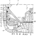
- annular intermediate wall 4 Inside the rotor body there is an annular intermediate wall 4 arranged coaxially with the rotor and connected to this at its centre. Further inside the rotor body there are arranged two axially movable annular slides 5 and 6. The slide 5 is located between the intermediate wall 4 and the upper rotor part 1. At its radially outer edge the slide 5 is an upper position is arranged to sealingly abut against the rotor part 1. Between the rotor part 1 and the slide 5 there is formed a separation chamber 7.
- the rotor part 2 Radially outside the area for the abutment of the slide 5 against the rotor part 1, the rotor part 2 has a number of openings 8 distributed around the circumference of the rotor intended to serve as peripheral outlets from the separation chamber when the slide 5 is located in a lower position and a gap is at hand between the slide 5 and the rotor part 1. Between the slide 5 and the intermediate wall 4 there is formed an annular chamber 9.
- the slide 6 is located between the intermediate wall 4 and the rotor part 2.
- a part of the slide 6 is essentially cylindrical and extends via a space between the rotor part 2 and the radially outermost part of the intermediate wall 4 into the chamber 9.
- the other part of the slide 6 is located in a chamber formed between the rotor part 2 and a radially outer part of the intermediate wall 4.
- the latter part of the slide 6 divides the said chamber into a first compartment 10 between the slide 6 and the intermediate wall 4 and a second compartment 11 between the slide 6 and the rotor part 2.
- the first compartment 10 has a throttled peripheral outlet comprising a channel 12 through the slide 6 and a channel 13 through the rotor part 2.
- the second compartment 11 has an inlet 14 for control liquid intended for axial movement of the slide 6.
- Gaskets 15 and 16 are arranged to seal between the slide 6 and the surrounding part of the rotor part 2.
- a sealing 17 is arranged to seal between the intermediate wall 4 and the surrounding cylindrical part of the slide 6.
- At 18 there is shown a number of radially and axially extending wings connected to the intermediate wall 4. Similar wings are supported by the intermediate wall 4 at 19, 20 and 21 and by the slide 6 at 22.
- the wings 21 are located in a chamber which via a channel 23 communicates with the interior of the driving shaft 3, in which there is maintained a free liquid surface marked with a triangle.
- the intermediate wall 4 has at the radially outer part of the just mentioned space a number of axially through passing bore holes 24. Via the channel 23, the space around the wings 21, and the bore holes 24, the interior of the driving shaft 3 communicates with the annular chamber 9. Via a channel 25, which opens radially inside the liquid surface in the interior of the driving shaft 3, this interior of the driving shaft 3 also communicates directly with the radially innermost part of the chamber 9.
- the rotor body In communication with the control liquid inlet 14 the rotor body forms a radially inwards open groove 26, which can be charged with control liquid from a not shown supplying device.
- the centrifugal rotor shown on the drawing functions in the following manner.
- the liquid surface in the chamber 9 moves an additional bit radially outwards until the slide 6 has reached a lower end position.
- the liquid surface in the chamber 9 is located at a level C.
- the liquid surface in the separation chamber 7 moves radially outwards until the liquid pressure against the slide 5 has become less than the counter directed pressure from the liquid in the chamber 9.
- the slide 5 is then pressed upwards again to its position shown on the drawing and the liquid surface in the chamber 9 is displaced to a level D.
- annular recesses have been formed in oppositively located parts of the intermediate wall 4 and the slide 6. In these recesses the above mentioned wings 19 and 23 are placed.
Abstract
Description
Claims (7)
- A centrifugal separator having a rotor with a rotor body, an annular slide (5) coaxial with the rotor body and axially movable relative thereto to open and close openings (8) at the circumference of the rotor, an annular wall (4) connected to the rotor body and forming together with the slide (5) an annular chamber (9) arranged to receive and upon rotation of the rotor retain a liquid for hydraulic influence on the slide (5), an additional slide (6) axially movable relative to the rotor body and the annular wall (4), the additional slide extending axially into and having an axially directed surface exposed in a radially outer part of the annular chamber (9), and sealing means (15, 17) for sealing the additional slide to the rotor body and to the annular wall, characterised in that the sealing means (15, 17) are arranged to seal constantly the radially outer portion of the annular chamber by sealing constantly the additional slide (6) to the rotor body and to the annular wall (4) whereby the sealing is maintained during axial movement of the additional slide (6), so that upon axial movement in one direction the additional slide causes liquid to be displaced radially inwards in the annular chamber (9) by taking up an increasing part of the volume of the annular chamber, and upon axial movement in the other direction the additional slide causes liquid to be displaced radially outwards in the annular chamber (9) by taking up a decreasing part of the volume of the annular chamber.
- A centrifugal separator according to claim 1, wherein the additional slide (6) is ring shaped and exposes an annular surface in said chamber (9).
- A centrifugal separator according to claim 2, wherein the additional slide (6) has an annular part located radially between a surrounding part (2) of the rotor body and a radially outer part of the annular wall (4), said sealing means (15, 17) being arranged between the annular wall (4) and the additional slide (6) and between the additional slide (6) and said surrounding part (2) of the rotor body.
- A centrifugal separator according to claim 2 or 3, wherein the additional slide (6) forms with the annular wall a first compartment (10) arranged to receive a retain liquid for hydraulic influences on the additional slide (6) in said second direction.
- A centrifugal separator according to claim 4, wherein the additional slide (6) forms with the rotor body a second compartment (11) arranged to receive and to retain liquid for hydraulic influence on the additional slide (6) in said one direction.
- A centrifugal separator according to any of the previous claims wherein a rotor encloses a separation chamber (7) with peripheral outlets (8) for a separated product, and said annular slide (5) is arranged for closing and intermittently opening of said outlets from the separation chamber (7).
- A centrifugal separator according to claim 6, wherein the annular slide (5) forms an essential part of an axially movable end wall in the separation chamber (7).
Applications Claiming Priority (3)
| Application Number | Priority Date | Filing Date | Title |
|---|---|---|---|
| SE8604907A SE457856B (en) | 1986-11-17 | 1986-11-17 | Centrifugal separator with an axially movable annular wear |
| SE8604907 | 1986-11-17 | ||
| PCT/SE1987/000534 WO1988003839A1 (en) | 1986-11-17 | 1987-11-16 | Operating system for centrifugal separator |
Publications (2)
| Publication Number | Publication Date |
|---|---|
| EP0332639A1 EP0332639A1 (en) | 1989-09-20 |
| EP0332639B1 true EP0332639B1 (en) | 1998-01-28 |
Family
ID=20366306
Family Applications (1)
| Application Number | Title | Priority Date | Filing Date |
|---|---|---|---|
| EP87907836A Expired - Lifetime EP0332639B1 (en) | 1986-11-17 | 1987-11-16 | Operating system for centrifugal separator |
Country Status (6)
| Country | Link |
|---|---|
| US (1) | US4925442A (en) |
| EP (1) | EP0332639B1 (en) |
| JP (1) | JPH0822394B2 (en) |
| DE (1) | DE3752166T2 (en) |
| SE (1) | SE457856B (en) |
| WO (1) | WO1988003839A1 (en) |
Families Citing this family (18)
| Publication number | Priority date | Publication date | Assignee | Title |
|---|---|---|---|---|
| SE9700495D0 (en) | 1997-02-12 | 1997-02-12 | Omega Medicinteknik Ab | Method and round bag system and centrifuge for blood treatment |
| SE516321C2 (en) | 1999-05-31 | 2001-12-17 | Gambro Inc | Centrifuge for the treatment of blood and blood components |
| SE517032C2 (en) | 1999-10-26 | 2002-04-02 | Gambro Inc | Method and apparatus for treating blood and blood components |
| US6706180B2 (en) * | 2001-08-13 | 2004-03-16 | Phase Inc. | System for vibration in a centrifuge |
| US20030173274A1 (en) * | 2002-02-01 | 2003-09-18 | Frank Corbin | Blood component separation device, system, and method including filtration |
| CA2642653A1 (en) | 2002-04-16 | 2003-10-30 | Gambro Bct, Inc. | Blood component processing system, apparatus and method |
| DE10220757B4 (en) * | 2002-05-08 | 2004-06-24 | Westfalia Separator Ag | Centrifuge, especially separator |
| US7320750B2 (en) * | 2003-03-11 | 2008-01-22 | Phase Inc. | Centrifuge with controlled discharge of dense material |
| US6971525B2 (en) * | 2003-06-25 | 2005-12-06 | Phase Inc. | Centrifuge with combinations of multiple features |
| EP1663459A4 (en) * | 2003-07-30 | 2007-11-07 | Phase Inc | Filtration system and dynamic fluid separation method |
| WO2005011833A2 (en) * | 2003-07-30 | 2005-02-10 | Phase Inc. | Filtration system with enhanced cleaning and dynamic fluid separation |
| US7282147B2 (en) * | 2003-10-07 | 2007-10-16 | Phase Inc. | Cleaning hollow core membrane fibers using vibration |
| US20060104863A1 (en) * | 2004-11-12 | 2006-05-18 | Bell Michael L | Sample preparation system for a laboratory apparatus |
| RU2529524C2 (en) | 2010-02-25 | 2014-09-27 | Альфа Лаваль Корпорейт Аб | Device and method for exhaust gas cleaning and fluid for gas flushing |
| WO2012012343A1 (en) | 2010-07-19 | 2012-01-26 | Caridianbct, Inc. | A centrifuge for processing blood and blood components |
| EP2774684B1 (en) * | 2013-03-06 | 2018-10-17 | Alfa Laval Corporate AB | A centrifugal separator |
| CN103691581B (en) * | 2013-12-17 | 2015-09-02 | 青岛诺凯达机械制造有限公司 | A kind of Tubular centrifuge drum and control method |
| US10654050B1 (en) * | 2019-05-21 | 2020-05-19 | Empirical Innovations, Inc. | Centrifugal separators and separation methods employing multiple pistons and facilitating intermediate material ejection |
Family Cites Families (8)
| Publication number | Priority date | Publication date | Assignee | Title |
|---|---|---|---|---|
| DE2363741B2 (en) * | 1973-12-21 | 1976-06-16 | CONTROL UNIT FOR A SELF-DRAINING FULL-SLEEVE CENTRIFUGE | |
| DE2521838B2 (en) * | 1975-05-16 | 1979-06-28 | Westfalia Separator Ag, 4740 Oelde | Spin drum of a self-cleaning centrifuge |
| DE2538630C2 (en) * | 1975-08-30 | 1982-09-09 | Westfalia Separator Ag, 4740 Oelde | Self-cleaning centrifuge drum |
| DE3208808C2 (en) * | 1982-03-11 | 1984-11-22 | Westfalia Separator Ag, 4740 Oelde | Centrifuge with a self-cleaning centrifugal drum |
| DE3240998C2 (en) * | 1982-11-06 | 1985-05-30 | Westfalia Separator Ag, 4740 Oelde | Centrifuge with a self-cleaning centrifugal drum |
| SE444652B (en) * | 1984-09-06 | 1986-04-28 | Alfa Laval Separation Ab | CENTRIFUGAL SEAT MANOVER SYSTEM |
| DE3509139C1 (en) * | 1985-03-14 | 1986-04-17 | Westfalia Separator Ag, 4740 Oelde | Centrifuge with a self-draining centrifuge |
| DE3524731C1 (en) * | 1985-07-11 | 1986-11-27 | Westfalia Separator Ag, 4740 Oelde | Centrifuge with a self-draining centrifuge |
-
1986
- 1986-11-17 SE SE8604907A patent/SE457856B/en not_active IP Right Cessation
-
1987
- 1987-11-16 WO PCT/SE1987/000534 patent/WO1988003839A1/en active IP Right Grant
- 1987-11-16 EP EP87907836A patent/EP0332639B1/en not_active Expired - Lifetime
- 1987-11-16 DE DE3752166T patent/DE3752166T2/en not_active Expired - Fee Related
- 1987-11-16 JP JP63500109A patent/JPH0822394B2/en not_active Expired - Lifetime
- 1987-11-16 US US07/346,949 patent/US4925442A/en not_active Expired - Fee Related
Also Published As
| Publication number | Publication date |
|---|---|
| US4925442A (en) | 1990-05-15 |
| DE3752166D1 (en) | 1998-03-05 |
| JPH0822394B2 (en) | 1996-03-06 |
| EP0332639A1 (en) | 1989-09-20 |
| SE8604907L (en) | 1988-05-18 |
| WO1988003839A1 (en) | 1988-06-02 |
| JPH02500497A (en) | 1990-02-22 |
| SE457856B (en) | 1989-02-06 |
| SE8604907D0 (en) | 1986-11-17 |
| DE3752166T2 (en) | 1998-05-14 |
Similar Documents
| Publication | Publication Date | Title |
|---|---|---|
| EP0332639B1 (en) | Operating system for centrifugal separator | |
| US6358193B1 (en) | Regulation device for a centrifugal separator to control discharge from outlets | |
| US3550843A (en) | Sludge centrifuge | |
| US4354632A (en) | Operating system for centrifuges | |
| US4103822A (en) | Centrifugal separator | |
| US4717376A (en) | Centrifuge with a self-emptying drum | |
| US3765599A (en) | Self cleaning centrifuge drum with stepwise variable closing pressure | |
| EP0197063B1 (en) | Centrifugal separator | |
| US2178547A (en) | Centrifugal separator | |
| US4027820A (en) | Self-cleaning centrifugal drum for the periodical removal of a portion of the solids separated from a liquid and collecting in the peripheral part of the interior of the drum | |
| US2723799A (en) | Centrifugal separation | |
| US4151951A (en) | Self-dumping centrifugal separator | |
| JPS6239013B2 (en) | ||
| US4479788A (en) | Centrifuge with a self-emptying drum | |
| US4643708A (en) | Centrifuge operating system | |
| US3085743A (en) | Sludge discharging centrifugal separators | |
| JPS6322868B2 (en) | ||
| US3081028A (en) | Periodic sludge discharging centrifugal drum separators | |
| US3415446A (en) | Hydraulically actuated valve plate for a centrifuge | |
| KR920010883B1 (en) | Maintaining closing-liquid level in centrifuges for operating slide valves | |
| US2551041A (en) | Valve device in centrifugal separators for separating sludge from liquids | |
| US3648926A (en) | Liquid-solid separator | |
| US3985292A (en) | Self-cleaning centrifuge drum with a piston valve defining one side of the sludge chamber | |
| KR830001160B1 (en) | Actuator for centrifuge | |
| JPS5813221B2 (en) | Self-discharging centrifugal drum |
Legal Events
| Date | Code | Title | Description |
|---|---|---|---|
| PUAI | Public reference made under article 153(3) epc to a published international application that has entered the european phase |
Free format text: ORIGINAL CODE: 0009012 |
|
| AK | Designated contracting states |
Kind code of ref document: A1 Designated state(s): DE FR GB IT SE |
|
| 17P | Request for examination filed |
Effective date: 19890508 |
|
| 17Q | First examination report despatched |
Effective date: 19920224 |
|
| APCB | Communication from the board of appeal sent |
Free format text: ORIGINAL CODE: EPIDOS OBAPE |
|
| APAB | Appeal dossier modified |
Free format text: ORIGINAL CODE: EPIDOS NOAPE |
|
| GRAG | Despatch of communication of intention to grant |
Free format text: ORIGINAL CODE: EPIDOS AGRA |
|
| GRAH | Despatch of communication of intention to grant a patent |
Free format text: ORIGINAL CODE: EPIDOS IGRA |
|
| GRAH | Despatch of communication of intention to grant a patent |
Free format text: ORIGINAL CODE: EPIDOS IGRA |
|
| GRAA | (expected) grant |
Free format text: ORIGINAL CODE: 0009210 |
|
| ITF | It: translation for a ep patent filed |
Owner name: BARZANO' E ZANARDO MILANO S.P.A. |
|
| AK | Designated contracting states |
Kind code of ref document: B1 Designated state(s): DE FR GB IT SE |
|
| PG25 | Lapsed in a contracting state [announced via postgrant information from national office to epo] |
Ref country code: FR Free format text: LAPSE BECAUSE OF FAILURE TO SUBMIT A TRANSLATION OF THE DESCRIPTION OR TO PAY THE FEE WITHIN THE PRESCRIBED TIME-LIMIT Effective date: 19980128 |
|
| REF | Corresponds to: |
Ref document number: 3752166 Country of ref document: DE Date of ref document: 19980305 |
|
| PG25 | Lapsed in a contracting state [announced via postgrant information from national office to epo] |
Ref country code: SE Free format text: LAPSE BECAUSE OF FAILURE TO SUBMIT A TRANSLATION OF THE DESCRIPTION OR TO PAY THE FEE WITHIN THE PRESCRIBED TIME-LIMIT Effective date: 19980428 |
|
| EN | Fr: translation not filed | ||
| PG25 | Lapsed in a contracting state [announced via postgrant information from national office to epo] |
Ref country code: GB Free format text: LAPSE BECAUSE OF NON-PAYMENT OF DUE FEES Effective date: 19981116 |
|
| PLBE | No opposition filed within time limit |
Free format text: ORIGINAL CODE: 0009261 |
|
| STAA | Information on the status of an ep patent application or granted ep patent |
Free format text: STATUS: NO OPPOSITION FILED WITHIN TIME LIMIT |
|
| 26N | No opposition filed | ||
| GBPC | Gb: european patent ceased through non-payment of renewal fee |
Effective date: 19981116 |
|
| PGFP | Annual fee paid to national office [announced via postgrant information from national office to epo] |
Ref country code: DE Payment date: 20021121 Year of fee payment: 16 |
|
| PG25 | Lapsed in a contracting state [announced via postgrant information from national office to epo] |
Ref country code: DE Free format text: LAPSE BECAUSE OF NON-PAYMENT OF DUE FEES Effective date: 20040602 |
|
| APAH | Appeal reference modified |
Free format text: ORIGINAL CODE: EPIDOSCREFNO |
|
| PG25 | Lapsed in a contracting state [announced via postgrant information from national office to epo] |
Ref country code: IT Free format text: LAPSE BECAUSE OF NON-PAYMENT OF DUE FEES;WARNING: LAPSES OF ITALIAN PATENTS WITH EFFECTIVE DATE BEFORE 2007 MAY HAVE OCCURRED AT ANY TIME BEFORE 2007. THE CORRECT EFFECTIVE DATE MAY BE DIFFERENT FROM THE ONE RECORDED. Effective date: 20051116 |