EP0332307A2 - Return electrode contact monitor for a HF surgical apparatus - Google Patents
Return electrode contact monitor for a HF surgical apparatus Download PDFInfo
- Publication number
- EP0332307A2 EP0332307A2 EP89301514A EP89301514A EP0332307A2 EP 0332307 A2 EP0332307 A2 EP 0332307A2 EP 89301514 A EP89301514 A EP 89301514A EP 89301514 A EP89301514 A EP 89301514A EP 0332307 A2 EP0332307 A2 EP 0332307A2
- Authority
- EP
- European Patent Office
- Prior art keywords
- return electrode
- resistance
- output
- electrode contact
- voltage
- Prior art date
- Legal status (The legal status is an assumption and is not a legal conclusion. Google has not performed a legal analysis and makes no representation as to the accuracy of the status listed.)
- Granted
Links
Images


Classifications
-
- A—HUMAN NECESSITIES
- A61—MEDICAL OR VETERINARY SCIENCE; HYGIENE
- A61B—DIAGNOSIS; SURGERY; IDENTIFICATION
- A61B18/00—Surgical instruments, devices or methods for transferring non-mechanical forms of energy to or from the body
- A61B18/04—Surgical instruments, devices or methods for transferring non-mechanical forms of energy to or from the body by heating
- A61B18/12—Surgical instruments, devices or methods for transferring non-mechanical forms of energy to or from the body by heating by passing a current through the tissue to be heated, e.g. high-frequency current
- A61B18/14—Probes or electrodes therefor
- A61B18/16—Indifferent or passive electrodes for grounding
-
- Y—GENERAL TAGGING OF NEW TECHNOLOGICAL DEVELOPMENTS; GENERAL TAGGING OF CROSS-SECTIONAL TECHNOLOGIES SPANNING OVER SEVERAL SECTIONS OF THE IPC; TECHNICAL SUBJECTS COVERED BY FORMER USPC CROSS-REFERENCE ART COLLECTIONS [XRACs] AND DIGESTS
- Y10—TECHNICAL SUBJECTS COVERED BY FORMER USPC
- Y10S—TECHNICAL SUBJECTS COVERED BY FORMER USPC CROSS-REFERENCE ART COLLECTIONS [XRACs] AND DIGESTS
- Y10S128/00—Surgery
- Y10S128/908—Patient protection from electric shock
Definitions
- This invention generally relates to electrosurgical apparatus and more particularly to a novel and improved return electrode monitor for electrosurgical apparatus.
- Electrosurgical apparatus which produces high frequency currents for cutting tissue and the coagulation of small blood vessels in electrosurgery are well known.
- the monitoring approach taken by Newton et al. is to use a voltage divider and a synchronous detector along with an automatic rather than a manual operation.
- Newton et al. automatically interprets a safe resistance representative of safe pad contact as the lowest resistance value observed over some period of time and automatically sets the upper limit of resistance as a function of that value.
- the disadvantage of this approach is that the circuit is more complex and therefore more costly and is less safe than a manual operation.
- An automatic operation does not allow the user which is typically the clinical staff to register concurrence that the pad has been properly applied.
- this disclosure does not provide a display of the measured resistance.
- a return electrode contact monitor includes a DC to AC converter providing a substantially DC voltage at its DC input that varies in relation to a resistance at its AC output.
- the resistance being monitored is the resistance of the return part of the patient circuit which is coupled to the output of the DC to AC converter via a high-isolation transformer to isolate the monitor from RF voltages in the patient circuit during surgical operations.
- a preferred DC to AC converter is a constant current fed high-efficiency sinusoidal oscillator.
- An analog to digital converter converts the substantially DC voltage to a corresponding binary digital signal that is input to a programmed microprocessor.
- the microprocessor is responsive to a manually operable set point switch, selected activation requests and can be set for either a single or dual foil mode.
- the microprocessor establishes preselected fixed maximum and minimum resistance value limits beyond which an alarm output is produced as well as a threshold so that upon a preselected fixed deviation of the resistance beyond a resistance value at the instant of the last selected set point switch activation an alarm output is produced.
- the microprocessor produces an output to turn off the RF power source each time an alarm output is produced.
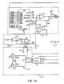
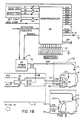
- FIG. 1A and 1B of the drawing there is shown monopolar electrosurgical apparatus which includes a conventional RF power source 11 having its output coupled by a transformer T3 to a patient circuit 12.
- the patient circuit 12 shown in Figure 1B has the active electrode 13 connected to the secondary winding of the transformer T3 via a capacitor C10.
- a dual foil return electrode 14 shown in the patient circuit includes two foils F1 and F2 that are in contact with patient P through which the electrosurgical current passes during surgical operations.
- the resistance across coupling terminals 15 and 16 is the resistance of RL plus both RW's.
- RL represents the resistance of the tissue of patient P connected between the dual foils F1 and F2.
- Foils F1 and F2 are shown connected via wire resistances RW to coupling terminals 15 and 16, respectively.
- Wire resistances RW are generally small in relation to RL and for purposes of analysis can be ignored.
- the resistance of the return part of the patient circuit through which monitoring current flows is RL plus both RW's and this is the resistance across terminals 15 and 16 that is monitored for the dual foil return electrode of Figure 1.
- the circuit through which the electrosurgical current flows during surgical operations includes active electrode 13, the patient, foils F1 and F2, resistors RW, capacitors C7 and C8 connected across the connecting terminals 15 and 16, a capacitor C9 connected to a common connection of capacitors C7 and C8, the secondary winding of transformer T3, and capacitor C10.
- the single foil return electrode 24 shown in Figure 2 consists of a single foil F3 having a patient P in contact therewith together with two wire resistances RW between the foil and connecting terminals 15 and 16.
- the resistance of the return part of the patient circuit for the single foil return electrode 24 is the resistance of both resistances RW.
- a patient plate fault condition and alarm output is produced when the resistance rises above the fixed minimum RMIN for the dual-foil mode of operation described more fully hereinafter.
- the terms return electrode, pad, and plate as used herein are the element that comes into contact with the patient and are synonymous.
- the return electrode contact monitor of the present invention measures the quality of the contact between the return electrode and the patient. More specifically, the return electrode contact monitor, generally stated, includes a DC to AC converter 21 coupled to the return electrode 14 via an isolation transformer T2, an analog to digital converter 22 converting the output of the converter 21 to a corresponding binary digital signal and a programmed microprocessor 25 that receives the binary digital signal, other selected inputs and controls the output of RF power source 11 to the active electrode 13, and provides other selected outputs described hereafter.
- the converter 21 shown includes a push-pull sine wave oscillator 25 and a low pass filter inclusive of inductor L1 and capacitor C3 between the output of the oscillator and the output of a constant current source 26.
- the oscillator is powered by constant current source 26.
- the oscillator includes transistors Q1 and Q2 having emitters connected to ground.
- a resistor R8 connects from the base of transistor Q2 to one side of the primary winding of transformer T1.
- a resistor R9 connects from the base of transistor Q1 to the other side of the primary winding of transformer T1.
- the collector of transistor Q2 connects to the common side of resistor R9 and the primary winding of transformer T1.
- a capacitor C4 is connected across the primary winding of transformer T1.
- a center tap of the primary of transformer T1 connects through the low pass filter of an inductor L1 and capacitor C3 to a voltage terminal VS which is the DC input of converter 21.
- An isolation transformer T2 has a primary winding connected through resistors R10 and R11 across the secondary winding of transformer T1. The center of the primary winding of transformer T2 is connected to ground.
- a capacitor C5 connects from one side of the secondary winding of T1 and ground and a capacitor C6 connects from the other side of the secondary winding of T1 and ground.
- the secondary winding of the isolation transformer is connected to the return pad terminals 15 and 16 of the patient circuit.
- Resistors R10 and R11 serve to establish a minimum resistance appearing across the output of transformer T1. These resistors allow the oscillator to continue operating at close to the normal operating frequency despite a short circuit at the pad terminals 15 and 16.
- the constant current source 26 includes an adjustable voltage regulator U1 which in conjunction with resistor R1 will deliver a substantially constant direct current designated IS.
- a resistor R2 is connected between the output of U1 and ground and serves to absorb the minimum load current from regulator U1 which exceeds the desired value for current IS.
- the constant current, IS, supplied by source 26, powers the oscillator via the filter inductor L1.
- the purpose of filter C3, L1 is to hold IS steady over the full cycle of oscillation of the oscillator 25 despite oscillatory voltage variations on the center tap of transformer T1.
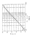
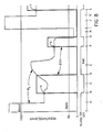
- FIG. 6 there is shown a plot of VS of converter 21 and the resistance RL across terminals 15 and 16 on a logarithm graph.
- Curve M is the actual plot and curve L is the ideal plot which is a straight line. This plot shows that the VS varies in a substantially logarithmic relationship with the return resistance of the patient circuit when the DC input current of converter 21 is constant.
- both transistors Q1 and Q2 will be turned off, and current IS will flow in nearly equal proportions through resistors R8 and R9 into the bases of transistors Q1 and Q2. Because of unavoidable thermal noise and differences in gain, one of the two transistors will begin to conduct collector current more heavily than the other. Say, for example, that Q1 begins conducting more heavily than Q2. The collector voltage of Q1 will be lower than Q2's, so more base current will flow through R9 than through R8. This will cause Q1 to conduct even more heavily and Q2 will be turned off due to lack of base current. Now substantially all of current IS will flow in Q1's collector, whose voltage will be quite low, and the collector voltage on Q2 will rise unimpeded by collector current. Some of IS supplies the base of Q1.
- Capacitors C5 and C6 may be thought of as being transformed to a single capacitor in parallel with C4, forming a parallel resonant LC circuit with the primary magnetizing inductance of transformer T1. Since T1 has a high Q, the voltage on the primary winding of T1 is forced to take on a nearly pure sinusoidal waveshape, gaining its energy from IS. The dominant Q-limiting mechanism is the base resistors R8 and R9. This forces the collector voltage on Q2 to take the form of the positive half-cycle of a sine wave, rising to a peak value VP after 90 degrees and falling toward zero approaching 180 degrees.
- Q1 draws its base current from Q2's collector voltage
- Q1 will cease to conduct when Q2's collector voltage falls below Q1's base-emitter forward voltage of about 0.7 V.
- the primary tank will sustain the sine wave and L1 will sustain current IS
- Q1's collector voltage will begin to rise, and Q2 will now turn on, robbing Q1 of any base current.
- the second half-cycle will now continue, with Q1 and Q2's roles reversed.
- the voltage amplitude of the primary circuit oscillation will progressively rise from cycle to cycle until current IS is only just adequate to sustain the power losses in the oscillator circuit and that in any resistance appearing at the secondary winding of transformer T2.
- the voltage waveform appearing at the center-tap of the primary winding of transformer T1 will take the form of a full-wave rectified sinewave with a peak amplitude of VP/2, since Q1 and Q2 collectors are essentially grounded on alternate half-cycles.
- the DC component of such a signal is 2/Pi or about 0.637 times the peak voltage of the waveform.
- inductor L1 exhibits negligible DC impedance
- the DC value of VS will be identical to that of T1.
- L1 also exhibits a high impedance at the frequency of oscillation, and C3 exhibits a low reactance, so voltage VS will appear as a nearly pure or a substantially DC voltage.
- VS will vary in direct proportion to the amplitude of the AC voltage on T1 primary, plus an offset of about 0.7 volts due to the forward base-emitter voltage of the transistors.
- Transformer T2 serves to isolate the monitor circuitry and specifically the oscillator from the high RF voltages which are applied to the patient circuit and specifically through active electrode 13 during electrosurgery. For the dual foil mode the current splits so that half flows through each of capacitors C7 and C8. Capacitors C9 and C10 serve to minimize low frequency components of the electrosurgical current.
- T1 comprises a TDK H6B RM8A400 core wound with a 79-turn bifilar pair of #32AWG magnet wire for the primary and an 18-turn #22AWG secondary.
- a copper Faraday shield is interposed between the two windings to minimize the effects of electrosurgical output voltages on the operation of the monitor circuit.
- a low-pass filter is formed by resistor R3 and capacitor C1 to further attenuate any high-frequency noise components or voltage appearing on VS.
- An operational amplifier U2 serves as a high-input-impedance buffer, preventing the comparator circuitry from absorbing a portion of IS and thus inducing errors in voltage VS.
- An 8-bit digital-to-analog converter U3 is driven by the microprocessor. Converter U3 generates a DC output voltage in response to data transferred over data bus represented by lines ADO - AD7 when control lines /IDAC and /WR are activated. The output voltage of U3 is compared to the buffered VS by a comparator U4, which incorporates a small amount (about 5mV) of hysteresis on the voltage VS.
- the microprocessor 23 executes a conventional successive approximation algorithm to determine a digital representation of the actual value of voltage VS.
- the microprocessor 23 is programmed to establish a range of resistance between preselected fixed maximum and minimum resistance value limits, RMAX and RMIN, beyond which an alarm output is produced.
- the microprocessor is further programmed to establish a preselected threshold value of resistance RTH whereby upon a preselected deviation of the resistance value at the instant of the last selected set point switch activation an alarm output is produced.
- Push-button switch S1 coupled to the microprocessor allows the user to select between dual- foil and single-foil return electrode modes. The selection is displayed by illumination of either LED I1 or I2.
- bar graph LED display I3 is driven by the microprocessor to indicate the measured resistance. Resistances below the predetermined minimum RMIN result in illumination of none of the LED bars in I3, while resistances exceeding the maximum RMAX result in illumination of all bars. Intermediate resistances are displayed as progressive illumination of I3 bars from left to right as resistance rises from the minimum to the maximum of the range.
- the set point switch S2 is pressed by the user to register satisfactory pad placement. These activations are ignored if the pad resistance lies outside the allowed range or if single-foil mode is selected.
- LED I4 is illuminated by the microprocessor whenever a patient plate fault condition is detected which results in an alarm output. That condition is defined as: In single-foil mode, detected resistance in excess of the allowed minimum RMIN for dual-foil mode, or In dual-foil mode, detected resistance either above RMAX or below RMIN, or In dual-foil mode, the detected resistance having risen by more than a predetermined percentage above the resistance present when the user last pressed set point switch S2, or In dual-foil mode, detected resistance within the allowed range, but not having been registered as valid by the user having activated S2 since the later of: selection of dual-foil mode, or detection plate fault producing an alarm output.
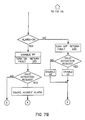
- microprocessor may be further understood with reference to a sequence of events shown in Figure 8 wherein the events are listed as follows:
- RTH KTxRL.
- a single transformer could be used for the oscillator and isolation and a potentiometer could be used for the set point switch as a set point means.
- Vacuum tubes could be used in place of the transistors.
- a circuit could provide current instead of voltage as a measure of the resistance. This could be voltage fed and the DC supply current measured.
Abstract
Description
- This invention generally relates to electrosurgical apparatus and more particularly to a novel and improved return electrode monitor for electrosurgical apparatus.
- Electrosurgical apparatus which produces high frequency currents for cutting tissue and the coagulation of small blood vessels in electrosurgery are well known.
- Recent examples of such apparatus are found in U.S. Patent Nos. 4,569,345, 4,574,801 and 4,617,927.
- Certain conditions of the return electrode may result in a burn to the patient. Some attempts have been made to monitor the return electrode to avoid injury to the patient. The disclosure of U. S. Patent Nos. 4,416,276 and 4,416,277 to Newton et al. are directed to monitoring the return electrode to insure the return electrode is in place and to avoid injury to the patient.
- The monitoring approach taken by Newton et al. is to use a voltage divider and a synchronous detector along with an automatic rather than a manual operation. Newton et al. automatically interprets a safe resistance representative of safe pad contact as the lowest resistance value observed over some period of time and automatically sets the upper limit of resistance as a function of that value. The disadvantage of this approach is that the circuit is more complex and therefore more costly and is less safe than a manual operation. An automatic operation does not allow the user which is typically the clinical staff to register concurrence that the pad has been properly applied. Moreover, this disclosure does not provide a display of the measured resistance.
- A return electrode contact monitor includes a DC to AC converter providing a substantially DC voltage at its DC input that varies in relation to a resistance at its AC output. The resistance being monitored is the resistance of the return part of the patient circuit which is coupled to the output of the DC to AC converter via a high-isolation transformer to isolate the monitor from RF voltages in the patient circuit during surgical operations. A preferred DC to AC converter is a constant current fed high-efficiency sinusoidal oscillator. An analog to digital converter converts the substantially DC voltage to a corresponding binary digital signal that is input to a programmed microprocessor. The microprocessor is responsive to a manually operable set point switch, selected activation requests and can be set for either a single or dual foil mode. The microprocessor establishes preselected fixed maximum and minimum resistance value limits beyond which an alarm output is produced as well as a threshold so that upon a preselected fixed deviation of the resistance beyond a resistance value at the instant of the last selected set point switch activation an alarm output is produced. The microprocessor produces an output to turn off the RF power source each time an alarm output is produced.
- A return electrode contact monitor embodying the invention is now described with reference to the accompanying drawings, in which:-
- Figures 1A and 1B are a circuit diagram of a return electrode monitor embodying features of the present invention with a dual foil return electrode in the patient circuit.
- Figure 2 is a schematic diagram of the single foil return electrode.
- Figure 3 is a graph showing the voltage and current waveforms for transistor Q1.
- Figure 4 is a graph showing the voltage and current waveforms for transistor Q2.
- Figure 5 is a graph showing voltage and current waveforms of the oscillator shown in Figure 1A.
- Figure 6 is a graph showing the relationship of resistance and the substantially DC voltage produced by the DC to AC converter.
- Figures 7A and 7B are a flow chart of the program for the microprocessor of Figure 1B.
- Figure 8 is a graph showing the relationship of resistance at the return part of the patient circuit and a variety of operational events together with the associated on-off positions for the alarm.
- Referring now to Figures 1A and 1B of the drawing, there is shown monopolar electrosurgical apparatus which includes a conventional
RF power source 11 having its output coupled by a transformer T3 to apatient circuit 12. Thepatient circuit 12 shown in Figure 1B has theactive electrode 13 connected to the secondary winding of the transformer T3 via a capacitor C10. A dualfoil return electrode 14 shown in the patient circuit includes two foils F1 and F2 that are in contact with patient P through which the electrosurgical current passes during surgical operations. The resistance acrosscoupling terminals coupling terminals terminals active electrode 13, the patient, foils F1 and F2, resistors RW, capacitors C7 and C8 connected across the connectingterminals - The single
foil return electrode 24 shown in Figure 2 consists of a single foil F3 having a patient P in contact therewith together with two wire resistances RW between the foil and connectingterminals - The resistance of the return part of the patient circuit for the single
foil return electrode 24 is the resistance of both resistances RW. A patient plate fault condition and alarm output is produced when the resistance rises above the fixed minimum RMIN for the dual-foil mode of operation described more fully hereinafter. The terms return electrode, pad, and plate as used herein are the element that comes into contact with the patient and are synonymous. - The return electrode contact monitor of the present invention, generally stated, measures the quality of the contact between the return electrode and the patient. More specifically, the return electrode contact monitor, generally stated, includes a DC to
AC converter 21 coupled to thereturn electrode 14 via an isolation transformer T2, an analog todigital converter 22 converting the output of theconverter 21 to a corresponding binary digital signal and a programmedmicroprocessor 25 that receives the binary digital signal, other selected inputs and controls the output ofRF power source 11 to theactive electrode 13, and provides other selected outputs described hereafter. - The
converter 21 shown includes a push-pullsine wave oscillator 25 and a low pass filter inclusive of inductor L1 and capacitor C3 between the output of the oscillator and the output of a constantcurrent source 26. The oscillator is powered by constantcurrent source 26. The oscillator includes transistors Q1 and Q2 having emitters connected to ground. A resistor R8 connects from the base of transistor Q2 to one side of the primary winding of transformer T1. A resistor R9 connects from the base of transistor Q1 to the other side of the primary winding of transformer T1. The collector of transistor Q2 connects to the common side of resistor R9 and the primary winding of transformer T1. A capacitor C4 is connected across the primary winding of transformer T1. A center tap of the primary of transformer T1 connects through the low pass filter of an inductor L1 and capacitor C3 to a voltage terminal VS which is the DC input ofconverter 21. - An isolation transformer T2 has a primary winding connected through resistors R10 and R11 across the secondary winding of transformer T1. The center of the primary winding of transformer T2 is connected to ground. A capacitor C5 connects from one side of the secondary winding of T1 and ground and a capacitor C6 connects from the other side of the secondary winding of T1 and ground. The secondary winding of the isolation transformer is connected to the
return pad terminals pad terminals - The constant
current source 26 includes an adjustable voltage regulator U1 which in conjunction with resistor R1 will deliver a substantially constant direct current designated IS. A resistor R2 is connected between the output of U1 and ground and serves to absorb the minimum load current from regulator U1 which exceeds the desired value for current IS. The constant current, IS, supplied bysource 26, powers the oscillator via the filter inductor L1. The purpose of filter C3, L1 is to hold IS steady over the full cycle of oscillation of theoscillator 25 despite oscillatory voltage variations on the center tap of transformer T1. - Referring now to Figure 6 there is shown a plot of VS of
converter 21 and the resistance RL acrossterminals converter 21 is constant. - In further explanation of the operation of
oscillator 25 and with particular reference to Figure 3, on startup, both transistors Q1 and Q2 will be turned off, and current IS will flow in nearly equal proportions through resistors R8 and R9 into the bases of transistors Q1 and Q2. Because of unavoidable thermal noise and differences in gain, one of the two transistors will begin to conduct collector current more heavily than the other. Say, for example, that Q1 begins conducting more heavily than Q2. The collector voltage of Q1 will be lower than Q2's, so more base current will flow through R9 than through R8. This will cause Q1 to conduct even more heavily and Q2 will be turned off due to lack of base current. Now substantially all of current IS will flow in Q1's collector, whose voltage will be quite low, and the collector voltage on Q2 will rise unimpeded by collector current. Some of IS supplies the base of Q1. - Capacitors C5 and C6 may be thought of as being transformed to a single capacitor in parallel with C4, forming a parallel resonant LC circuit with the primary magnetizing inductance of transformer T1. Since T1 has a high Q, the voltage on the primary winding of T1 is forced to take on a nearly pure sinusoidal waveshape, gaining its energy from IS. The dominant Q-limiting mechanism is the base resistors R8 and R9. This forces the collector voltage on Q2 to take the form of the positive half-cycle of a sine wave, rising to a peak value VP after 90 degrees and falling toward zero approaching 180 degrees. Since Q1 draws its base current from Q2's collector voltage, Q1 will cease to conduct when Q2's collector voltage falls below Q1's base-emitter forward voltage of about 0.7 V. Because the primary tank will sustain the sine wave and L1 will sustain current IS, Q1's collector voltage will begin to rise, and Q2 will now turn on, robbing Q1 of any base current. The second half-cycle will now continue, with Q1 and Q2's roles reversed. The voltage amplitude of the primary circuit oscillation will progressively rise from cycle to cycle until current IS is only just adequate to sustain the power losses in the oscillator circuit and that in any resistance appearing at the secondary winding of transformer T2.
- The voltage waveform appearing at the center-tap of the primary winding of transformer T1 will take the form of a full-wave rectified sinewave with a peak amplitude of VP/2, since Q1 and Q2 collectors are essentially grounded on alternate half-cycles. The DC component of such a signal is 2/Pi or about 0.637 times the peak voltage of the waveform. Because inductor L1 exhibits negligible DC impedance, the DC value of VS will be identical to that of T1. But L1 also exhibits a high impedance at the frequency of oscillation, and C3 exhibits a low reactance, so voltage VS will appear as a nearly pure or a substantially DC voltage. Thus VS will vary in direct proportion to the amplitude of the AC voltage on T1 primary, plus an offset of about 0.7 volts due to the forward base-emitter voltage of the transistors.
- Any resistive components appearing in parallel with the filter L1, C3 on T1 primary will extract energy from that circuit, causing a drop in the amplitude of the primary AC voltage. This will be reflected as a corresponding drop in VS; if that resistance were to rise, VS would thus rise accordingly. The most significant of those resistive components is RL which is reflected to T1 primary by the inverse square of the product of the turns ratios of T1 and T2. Transformers T1 and T2 may be considered as a single device for purposes of analysis, but their roles are distinct. Transformer T1 serves as a high Q magnetically coupled tuned circuit acting in conjunction with C7 and C8. Transformer T2 serves to isolate the monitor circuitry and specifically the oscillator from the high RF voltages which are applied to the patient circuit and specifically through
active electrode 13 during electrosurgery. For the dual foil mode the current splits so that half flows through each of capacitors C7 and C8. Capacitors C9 and C10 serve to minimize low frequency components of the electrosurgical current. - In a preferred embodiment, T1 comprises a TDK H6B RM8A400 core wound with a 79-turn bifilar pair of #32AWG magnet wire for the primary and an 18-turn #22AWG secondary. A copper Faraday shield is interposed between the two windings to minimize the effects of electrosurgical output voltages on the operation of the monitor circuit.
- A low-pass filter is formed by resistor R3 and capacitor C1 to further attenuate any high-frequency noise components or voltage appearing on VS. An operational amplifier U2 serves as a high-input-impedance buffer, preventing the comparator circuitry from absorbing a portion of IS and thus inducing errors in voltage VS. An 8-bit digital-to-analog converter U3 is driven by the microprocessor. Converter U3 generates a DC output voltage in response to data transferred over data bus represented by lines ADO - AD7 when control lines /IDAC and /WR are activated. The output voltage of U3 is compared to the buffered VS by a comparator U4, which incorporates a small amount (about 5mV) of hysteresis on the voltage VS.
- The
microprocessor 23 executes a conventional successive approximation algorithm to determine a digital representation of the actual value of voltage VS. Themicroprocessor 23 is programmed to establish a range of resistance between preselected fixed maximum and minimum resistance value limits, RMAX and RMIN, beyond which an alarm output is produced. The microprocessor is further programmed to establish a preselected threshold value of resistance RTH whereby upon a preselected deviation of the resistance value at the instant of the last selected set point switch activation an alarm output is produced. - Push-button switch S1 coupled to the microprocessor allows the user to select between dual- foil and single-foil return electrode modes. The selection is displayed by illumination of either LED I1 or I2. When dual-foil operation is selected, bar graph LED display I3 is driven by the microprocessor to indicate the measured resistance. Resistances below the predetermined minimum RMIN result in illumination of none of the LED bars in I3, while resistances exceeding the maximum RMAX result in illumination of all bars. Intermediate resistances are displayed as progressive illumination of I3 bars from left to right as resistance rises from the minimum to the maximum of the range.
- In dual-foil operation, the set point switch S2 is pressed by the user to register satisfactory pad placement. These activations are ignored if the pad resistance lies outside the allowed range or if single-foil mode is selected.
- LED I4 is illuminated by the microprocessor whenever a patient plate fault condition is detected which results in an alarm output. That condition is defined as:
In single-foil mode, detected resistance in excess of the allowed minimum RMIN for dual-foil mode, or
In dual-foil mode, detected resistance either above RMAX or below RMIN, or
In dual-foil mode, the detected resistance having risen by more than a predetermined percentage above the resistance present when the user last pressed set point switch S2, or
In dual-foil mode, detected resistance within the allowed range, but not having been registered as valid by the user having activated S2 since the later of:
selection of dual-foil mode, or
detection plate fault producing an alarm output. - Once a dual foil alarm has been declared, it will remain active until the resistance returns to within the allowable range and the set point is re-established by the user.
- The functions performed by the microprocessor may be further understood with reference to a sequence of events shown in Figure 8 wherein the events are listed as follows:
-
- A. Pad placed on patient and resistance is between RMAX and RMIN values.
- B. Set point switch S2 activated establishing first RTH limits at point a.
- C. Pad pulls loose gradually causing the resistance to increase.
- D. Resistance rises above threshold RTH, alarm goes on, and RF power source is inhibited.
- E. Pad contact restored by user OR staff.
- F. Set point switch S2 activated again to establish new RTH limits at point b.
- G. Pad shorts out dropping resistance below RMIN.
- H. Set point switch S2 activated - alarm continues since resistance is less than RMIN.
- I. Remove defective pad causing resistance to exceed RMAX.
- J. Set point switch S2 activation attempted - still rejected since resistance is greater than RMAX.
- K. Connect and attach new pad to patient.
- L. Activate set point switch S2 establishing new RTH limits at point c.
- By way of illustration only and not by way of limitation, there are listed below devices which have been found suitable for use in the illustrated circuits.
Reference No. Part No. U1 LM317L NATL. SEMICONDUCTOR U2 LM358 NATL. SEMICONDUCTOR U4 LM339 NATL. SEMICONDUCTOR U3 AD558 ANALOG DEVICES 23 8031 INTEL - The Q above described is greater than 200 at 40KHz. KT referred to in Figure 6 is a threshold constant where RTH = KTxRL. A preselected fixed deviation of the resistance value determined by the set point means of 20 to 30% has been shown to reliably indicate pad detachment prior to an unsafe degree of contact being established. In this case KT = 1.2 to 1.3.
- It is understood that a single transformer could be used for the oscillator and isolation and a potentiometer could be used for the set point switch as a set point means. Vacuum tubes could be used in place of the transistors. Moreover a circuit could provide current instead of voltage as a measure of the resistance. This could be voltage fed and the DC supply current measured.
- Although the present invention has been described with a certain degree of particularity, it is understood that the present disclosure has been made by way of example and that changes in details of structure may be made without departing from the spirit thereof.
Claims (17)
first means for producing an electric signal that varies with the resistance of a return part of the patient circuit, and
circuit means responsive to said electric signal, said circuit means establishing a preselected resistance value range beyond which an alarm output is produced, a manually operable set point actuator means, said circuit means including set point means responsive to said actuator means providing a threshold corresponding to the resistance at the last time said actuator means was actuated whereby upon a preselected fixed deviation of said resistance from said threshold and within said range an alarm output is produced.
detector means including a DC to AC converter in the form of a current fed push-pull sine wave oscillator and a low pass filter for producing a substantially DC voltage related to the resistance of the return part of the patient circuit, and
circuit means including an analog to digital converter and a programmed microprocessor, said converter converting said substantially DC voltage to a corresponding binary digital signal that is input to said micro-processor, a manually operable set point switch coupled to said microprocessor, said microprocessor establishing preselected fixed maximum and minimum resistance value limits beyond which an alarm output is produced and said microprocessor further including set point means providing a threshold corresponding to the resistance at the instant of the last set point switch activation whereby upon a preselected fixed deviation of said resistance above said threshold and within said maximum and minimum value limits an alarm output is produced, said microprocessor providing an output to shut off the RF power source each time an alarm output is produced.
Applications Claiming Priority (2)
| Application Number | Priority Date | Filing Date | Title |
|---|---|---|---|
| US156540 | 1988-02-16 | ||
| US07156540 US4848335B1 (en) | 1988-02-16 | 1988-02-16 | Return electrode contact monitor |
Publications (3)
| Publication Number | Publication Date |
|---|---|
| EP0332307A2 true EP0332307A2 (en) | 1989-09-13 |
| EP0332307A3 EP0332307A3 (en) | 1990-08-29 |
| EP0332307B1 EP0332307B1 (en) | 1995-11-29 |
Family
ID=22559984
Family Applications (1)
| Application Number | Title | Priority Date | Filing Date |
|---|---|---|---|
| EP89301514A Expired - Lifetime EP0332307B1 (en) | 1988-02-16 | 1989-02-16 | Return electrode contact monitor for a HF surgical apparatus |
Country Status (3)
| Country | Link |
|---|---|
| US (1) | US4848335B1 (en) |
| EP (1) | EP0332307B1 (en) |
| DE (1) | DE68924918T2 (en) |
Cited By (2)
| Publication number | Priority date | Publication date | Assignee | Title |
|---|---|---|---|---|
| EP0533360A1 (en) * | 1991-09-14 | 1993-03-24 | Smiths Industries Public Limited Company | Electrosurgery apparatus |
| GB2374532A (en) * | 2001-02-23 | 2002-10-23 | Smiths Group Plc | Electrosurgery apparatus monitoring impedance of split-plate return electrode |
Families Citing this family (100)
| Publication number | Priority date | Publication date | Assignee | Title |
|---|---|---|---|---|
| US4961047A (en) * | 1988-11-10 | 1990-10-02 | Smiths Industries Public Limited Company | Electrical power control apparatus and methods |
| US5209230A (en) * | 1990-10-19 | 1993-05-11 | Nellcor Incorporated | Adhesive pulse oximeter sensor with reusable portion |
| US5246003A (en) * | 1991-08-28 | 1993-09-21 | Nellcor Incorporated | Disposable pulse oximeter sensor |
| GB9306637D0 (en) * | 1993-03-30 | 1993-05-26 | Smiths Industries Plc | Electrosurgery monitor and appartus |
| US5695494A (en) * | 1994-12-22 | 1997-12-09 | Valleylab Inc | Rem output stage topology |
| US5797902A (en) * | 1996-05-10 | 1998-08-25 | Minnesota Mining And Manufacturing Company | Biomedical electrode providing early detection of accidental detachment |
| DE19623840A1 (en) * | 1996-06-14 | 1997-12-18 | Berchtold Gmbh & Co Geb | High frequency electrosurgical generator |
| DE19628482A1 (en) * | 1996-07-15 | 1998-01-22 | Berchtold Gmbh & Co Geb | Method for operating a high-frequency surgical device and high-frequency surgical device |
| DE19643127A1 (en) | 1996-10-18 | 1998-04-23 | Berchtold Gmbh & Co Geb | High frequency surgical device and method for its operation |
| CN1213701C (en) | 1997-04-04 | 2005-08-10 | 美国3M公司 | Method and apparatus for controlling contact of biomedical electrodes with patient skin |
| JP3315623B2 (en) * | 1997-06-19 | 2002-08-19 | オリンパス光学工業株式会社 | Return electrode peeling monitor of electrocautery device |
| US6007532A (en) | 1997-08-29 | 1999-12-28 | 3M Innovative Properties Company | Method and apparatus for detecting loss of contact of biomedical electrodes with patient skin |
| US7137980B2 (en) | 1998-10-23 | 2006-11-21 | Sherwood Services Ag | Method and system for controlling output of RF medical generator |
| US7364577B2 (en) | 2002-02-11 | 2008-04-29 | Sherwood Services Ag | Vessel sealing system |
| US7901400B2 (en) | 1998-10-23 | 2011-03-08 | Covidien Ag | Method and system for controlling output of RF medical generator |
| DE10102254A1 (en) * | 2001-01-19 | 2002-08-08 | Celon Ag Medical Instruments | Device for the electrothermal treatment of the human or animal body |
| US6796828B2 (en) * | 2001-06-01 | 2004-09-28 | Sherwood Services Ag | Return pad cable connector |
| ES2290797T3 (en) | 2001-06-01 | 2008-02-16 | Covidien Ag | CABLE CONNECTOR WITH A RETURN PAD. |
| US6676660B2 (en) | 2002-01-23 | 2004-01-13 | Ethicon Endo-Surgery, Inc. | Feedback light apparatus and method for use with an electrosurgical instrument |
| ATE371413T1 (en) | 2002-05-06 | 2007-09-15 | Covidien Ag | BLOOD DETECTOR FOR CHECKING AN ELECTROSURGICAL UNIT |
| US6860881B2 (en) * | 2002-09-25 | 2005-03-01 | Sherwood Services Ag | Multiple RF return pad contact detection system |
| US6948503B2 (en) * | 2002-11-19 | 2005-09-27 | Conmed Corporation | Electrosurgical generator and method for cross-checking output power |
| US6875210B2 (en) * | 2002-11-19 | 2005-04-05 | Conmed Corporation | Electrosurgical generator and method for cross-checking mode functionality |
| US6830569B2 (en) * | 2002-11-19 | 2004-12-14 | Conmed Corporation | Electrosurgical generator and method for detecting output power delivery malfunction |
| US7044948B2 (en) | 2002-12-10 | 2006-05-16 | Sherwood Services Ag | Circuit for controlling arc energy from an electrosurgical generator |
| ATE344637T1 (en) * | 2003-01-09 | 2006-11-15 | Ge Healthcare Finland Oy | SHIELDING ARRANGEMENT FOR ECG CONNECTION WIRES |
| EP1617776B1 (en) | 2003-05-01 | 2015-09-02 | Covidien AG | System for programing and controlling an electrosurgical generator system |
| EP1675499B1 (en) | 2003-10-23 | 2011-10-19 | Covidien AG | Redundant temperature monitoring in electrosurgical systems for safety mitigation |
| WO2005050151A1 (en) | 2003-10-23 | 2005-06-02 | Sherwood Services Ag | Thermocouple measurement circuit |
| US7396336B2 (en) | 2003-10-30 | 2008-07-08 | Sherwood Services Ag | Switched resonant ultrasonic power amplifier system |
| US7131860B2 (en) | 2003-11-20 | 2006-11-07 | Sherwood Services Ag | Connector systems for electrosurgical generator |
| US7300435B2 (en) * | 2003-11-21 | 2007-11-27 | Sherwood Services Ag | Automatic control system for an electrosurgical generator |
| US7766905B2 (en) | 2004-02-12 | 2010-08-03 | Covidien Ag | Method and system for continuity testing of medical electrodes |
| US7780662B2 (en) | 2004-03-02 | 2010-08-24 | Covidien Ag | Vessel sealing system using capacitive RF dielectric heating |
| ATE549989T1 (en) * | 2004-04-16 | 2012-04-15 | Sydney West Area Health Service | BIOMEDICAL RETURN ELECTRODE WITH THERMOCHROME LAYER |
| US7628786B2 (en) | 2004-10-13 | 2009-12-08 | Covidien Ag | Universal foot switch contact port |
| CA2541037A1 (en) * | 2005-03-31 | 2006-09-30 | Sherwood Services Ag | Temperature regulating patient return electrode and return electrode monitoring system |
| US9474564B2 (en) | 2005-03-31 | 2016-10-25 | Covidien Ag | Method and system for compensating for external impedance of an energy carrying component when controlling an electrosurgical generator |
| US7340294B2 (en) * | 2005-08-11 | 2008-03-04 | The General Electric Company | Impedance measurement apparatus for assessment of biomedical electrode interface quality |
| US8734438B2 (en) | 2005-10-21 | 2014-05-27 | Covidien Ag | Circuit and method for reducing stored energy in an electrosurgical generator |
| US7947039B2 (en) | 2005-12-12 | 2011-05-24 | Covidien Ag | Laparoscopic apparatus for performing electrosurgical procedures |
| US7736359B2 (en) | 2006-01-12 | 2010-06-15 | Covidien Ag | RF return pad current detection system |
| US20070167942A1 (en) * | 2006-01-18 | 2007-07-19 | Sherwood Services Ag | RF return pad current distribution system |
| US8216223B2 (en) | 2006-01-24 | 2012-07-10 | Covidien Ag | System and method for tissue sealing |
| US8147485B2 (en) | 2006-01-24 | 2012-04-03 | Covidien Ag | System and method for tissue sealing |
| US9186200B2 (en) | 2006-01-24 | 2015-11-17 | Covidien Ag | System and method for tissue sealing |
| CA2574935A1 (en) | 2006-01-24 | 2007-07-24 | Sherwood Services Ag | A method and system for controlling an output of a radio-frequency medical generator having an impedance based control algorithm |
| CA2574934C (en) | 2006-01-24 | 2015-12-29 | Sherwood Services Ag | System and method for closed loop monitoring of monopolar electrosurgical apparatus |
| US7513896B2 (en) | 2006-01-24 | 2009-04-07 | Covidien Ag | Dual synchro-resonant electrosurgical apparatus with bi-directional magnetic coupling |
| US7972328B2 (en) | 2006-01-24 | 2011-07-05 | Covidien Ag | System and method for tissue sealing |
| US8685016B2 (en) | 2006-01-24 | 2014-04-01 | Covidien Ag | System and method for tissue sealing |
| US7651493B2 (en) | 2006-03-03 | 2010-01-26 | Covidien Ag | System and method for controlling electrosurgical snares |
| US7648499B2 (en) | 2006-03-21 | 2010-01-19 | Covidien Ag | System and method for generating radio frequency energy |
| US7651492B2 (en) | 2006-04-24 | 2010-01-26 | Covidien Ag | Arc based adaptive control system for an electrosurgical unit |
| US8753334B2 (en) | 2006-05-10 | 2014-06-17 | Covidien Ag | System and method for reducing leakage current in an electrosurgical generator |
| US7731717B2 (en) | 2006-08-08 | 2010-06-08 | Covidien Ag | System and method for controlling RF output during tissue sealing |
| US8034049B2 (en) | 2006-08-08 | 2011-10-11 | Covidien Ag | System and method for measuring initial tissue impedance |
| US7722603B2 (en) | 2006-09-28 | 2010-05-25 | Covidien Ag | Smart return electrode pad |
| US7927329B2 (en) | 2006-09-28 | 2011-04-19 | Covidien Ag | Temperature sensing return electrode pad |
| US7794457B2 (en) | 2006-09-28 | 2010-09-14 | Covidien Ag | Transformer for RF voltage sensing |
| US8777940B2 (en) | 2007-04-03 | 2014-07-15 | Covidien Lp | System and method for providing even heat distribution and cooling return pads |
| US8021360B2 (en) | 2007-04-03 | 2011-09-20 | Tyco Healthcare Group Lp | System and method for providing even heat distribution and cooling return pads |
| US8080007B2 (en) | 2007-05-07 | 2011-12-20 | Tyco Healthcare Group Lp | Capacitive electrosurgical return pad with contact quality monitoring |
| US8777941B2 (en) | 2007-05-10 | 2014-07-15 | Covidien Lp | Adjustable impedance electrosurgical electrodes |
| US8388612B2 (en) | 2007-05-11 | 2013-03-05 | Covidien Lp | Temperature monitoring return electrode |
| US8231614B2 (en) | 2007-05-11 | 2012-07-31 | Tyco Healthcare Group Lp | Temperature monitoring return electrode |
| US20080312651A1 (en) * | 2007-06-15 | 2008-12-18 | Karl Pope | Apparatus and methods for selective heating of tissue |
| US7834484B2 (en) | 2007-07-16 | 2010-11-16 | Tyco Healthcare Group Lp | Connection cable and method for activating a voltage-controlled generator |
| US8100898B2 (en) | 2007-08-01 | 2012-01-24 | Tyco Healthcare Group Lp | System and method for return electrode monitoring |
| US8801703B2 (en) | 2007-08-01 | 2014-08-12 | Covidien Lp | System and method for return electrode monitoring |
| US8216220B2 (en) | 2007-09-07 | 2012-07-10 | Tyco Healthcare Group Lp | System and method for transmission of combined data stream |
| US8512332B2 (en) | 2007-09-21 | 2013-08-20 | Covidien Lp | Real-time arc control in electrosurgical generators |
| US20090171344A1 (en) * | 2007-12-26 | 2009-07-02 | George Pontis | Apparatus and methods for monitoring patient-apparatus contact |
| US9987072B2 (en) * | 2008-03-17 | 2018-06-05 | Covidien Lp | System and method for detecting a fault in a capacitive return electrode for use in electrosurgery |
| EP2364662B1 (en) | 2008-03-31 | 2013-10-23 | Applied Medical Resources Corporation | Electrosurgical system with a switching mechanism |
| US8172835B2 (en) | 2008-06-05 | 2012-05-08 | Cutera, Inc. | Subcutaneous electric field distribution system and methods |
| US20090306647A1 (en) * | 2008-06-05 | 2009-12-10 | Greg Leyh | Dynamically controllable multi-electrode apparatus & methods |
| US8226639B2 (en) | 2008-06-10 | 2012-07-24 | Tyco Healthcare Group Lp | System and method for output control of electrosurgical generator |
| US20100022999A1 (en) * | 2008-07-24 | 2010-01-28 | Gollnick David A | Symmetrical rf electrosurgical system and methods |
| US8262652B2 (en) | 2009-01-12 | 2012-09-11 | Tyco Healthcare Group Lp | Imaginary impedance process monitoring and intelligent shut-off |
| US20100211060A1 (en) * | 2009-02-13 | 2010-08-19 | Cutera, Inc. | Radio frequency treatment of subcutaneous fat |
| US8211097B2 (en) | 2009-02-13 | 2012-07-03 | Cutera, Inc. | Optimizing RF power spatial distribution using frequency control |
| US8298225B2 (en) * | 2009-03-19 | 2012-10-30 | Tyco Healthcare Group Lp | System and method for return electrode monitoring |
| US7956620B2 (en) | 2009-08-12 | 2011-06-07 | Tyco Healthcare Group Lp | System and method for augmented impedance sensing |
| US20110190755A1 (en) * | 2010-01-29 | 2011-08-04 | Medtronic Ablation Frontiers Llc | Patient return electrode detection for ablation system |
| EP3332723B1 (en) | 2010-10-01 | 2022-02-16 | Applied Medical Resources Corporation | Electrosurgical instruments and connections thereto |
| PL2537479T3 (en) * | 2011-06-20 | 2014-08-29 | Erbe Elektromedizin | Controlling a medical device depending on neutral electrode impedance |
| US10376301B2 (en) | 2011-09-28 | 2019-08-13 | Covidien Lp | Logarithmic amplifier, electrosurgical generator including same, and method of controlling electrosurgical generator using same |
| US9252743B2 (en) * | 2012-09-28 | 2016-02-02 | Intel Corporation | Distributed polyphase filter |
| US9861425B2 (en) | 2012-10-02 | 2018-01-09 | Covidien Lp | System and method for using resonance phasing for measuring impedance |
| US9872719B2 (en) | 2013-07-24 | 2018-01-23 | Covidien Lp | Systems and methods for generating electrosurgical energy using a multistage power converter |
| US9636165B2 (en) | 2013-07-29 | 2017-05-02 | Covidien Lp | Systems and methods for measuring tissue impedance through an electrosurgical cable |
| EP3142583B1 (en) | 2014-05-16 | 2023-04-12 | Applied Medical Resources Corporation | Electrosurgical system |
| WO2015184446A2 (en) | 2014-05-30 | 2015-12-03 | Applied Medical Resources Corporation | Electrosurgical seal and dissection systems |
| EP3236870B1 (en) | 2014-12-23 | 2019-11-06 | Applied Medical Resources Corporation | Bipolar electrosurgical sealer and divider |
| USD748259S1 (en) | 2014-12-29 | 2016-01-26 | Applied Medical Resources Corporation | Electrosurgical instrument |
| US10646266B2 (en) | 2015-11-13 | 2020-05-12 | Covidien Lp | System and method for return electrode monitoring |
| US20190083162A1 (en) | 2017-09-19 | 2019-03-21 | Biosense Webster (Israel) Ltd. | Electrode disconnect detection |
| WO2020051369A1 (en) | 2018-09-05 | 2020-03-12 | Applied Medical Resources Corporation | Electrosurgical generator control system |
| CA3120182A1 (en) | 2018-11-16 | 2020-05-22 | Applied Medical Resources Corporation | Electrosurgical system |
Citations (3)
| Publication number | Priority date | Publication date | Assignee | Title |
|---|---|---|---|---|
| FR2409487A1 (en) * | 1977-11-17 | 1979-06-15 | Valleylab Inc | APPARATUS AND METHOD FOR MEASURING THE SURFACE OF CONTACT WITH TISSUES OF AN ELECTRODE FOR ELECTROSURGERY AND CRYOSURGERY |
| FR2516782A1 (en) * | 1981-11-20 | 1983-05-27 | Alm | Electric surgical scalpel with HF current source - has active and return electrodes, generator and capacitive impedance monitor |
| US4416276A (en) * | 1981-10-26 | 1983-11-22 | Valleylab, Inc. | Adaptive, return electrode monitoring system |
Family Cites Families (7)
| Publication number | Priority date | Publication date | Assignee | Title |
|---|---|---|---|---|
| DE1139927B (en) * | 1961-01-03 | 1962-11-22 | Friedrich Laber | High-frequency surgical device |
| US3933157A (en) * | 1973-10-23 | 1976-01-20 | Aktiebolaget Stille-Werner | Test and control device for electrosurgical apparatus |
| US4416277A (en) * | 1981-11-03 | 1983-11-22 | Valleylab, Inc. | Return electrode monitoring system for use during electrosurgical activation |
| GB8324442D0 (en) * | 1983-09-13 | 1983-10-12 | Matburn Holdings Ltd | Electrosurgical system |
| US4617927A (en) * | 1984-02-29 | 1986-10-21 | Aspen Laboratories, Inc. | Electrosurgical unit |
| US4574801A (en) * | 1984-02-29 | 1986-03-11 | Aspen Laboratories, Inc. | Electrosurgical unit with regulated output |
| US4569345A (en) * | 1984-02-29 | 1986-02-11 | Aspen Laboratories, Inc. | High output electrosurgical unit |
-
1988
- 1988-02-16 US US07156540 patent/US4848335B1/en not_active Expired - Lifetime
-
1989
- 1989-02-16 DE DE68924918T patent/DE68924918T2/en not_active Expired - Lifetime
- 1989-02-16 EP EP89301514A patent/EP0332307B1/en not_active Expired - Lifetime
Patent Citations (3)
| Publication number | Priority date | Publication date | Assignee | Title |
|---|---|---|---|---|
| FR2409487A1 (en) * | 1977-11-17 | 1979-06-15 | Valleylab Inc | APPARATUS AND METHOD FOR MEASURING THE SURFACE OF CONTACT WITH TISSUES OF AN ELECTRODE FOR ELECTROSURGERY AND CRYOSURGERY |
| US4416276A (en) * | 1981-10-26 | 1983-11-22 | Valleylab, Inc. | Adaptive, return electrode monitoring system |
| FR2516782A1 (en) * | 1981-11-20 | 1983-05-27 | Alm | Electric surgical scalpel with HF current source - has active and return electrodes, generator and capacitive impedance monitor |
Non-Patent Citations (1)
| Title |
|---|
| Hans Sauer, "Relais-Lexikon",2nd edition, Hüthig Verlag Heidelberg, 1985, pages 118 and 119 * |
Cited By (4)
| Publication number | Priority date | Publication date | Assignee | Title |
|---|---|---|---|---|
| EP0533360A1 (en) * | 1991-09-14 | 1993-03-24 | Smiths Industries Public Limited Company | Electrosurgery apparatus |
| US5246439A (en) * | 1991-09-14 | 1993-09-21 | Smiths Industries Public Limited Company | Electrosurgery equipment |
| GB2374532A (en) * | 2001-02-23 | 2002-10-23 | Smiths Group Plc | Electrosurgery apparatus monitoring impedance of split-plate return electrode |
| GB2374532B (en) * | 2001-02-23 | 2004-10-06 | Smiths Group Plc | Electrosurgery apparatus |
Also Published As
| Publication number | Publication date |
|---|---|
| US4848335A (en) | 1989-07-18 |
| DE68924918D1 (en) | 1996-01-11 |
| EP0332307B1 (en) | 1995-11-29 |
| US4848335B1 (en) | 1994-06-07 |
| DE68924918T2 (en) | 1996-06-05 |
| EP0332307A3 (en) | 1990-08-29 |
Similar Documents
| Publication | Publication Date | Title |
|---|---|---|
| EP0332307B1 (en) | Return electrode contact monitor for a HF surgical apparatus | |
| US3875945A (en) | Electrosurgery instrument | |
| US4969885A (en) | High frequency surgery device for cutting and/or coagulating biologic tissue | |
| US5133711A (en) | Electric surgical high-frequency instrument | |
| AU681046B2 (en) | Electrosurgical generator adaptors | |
| US4191188A (en) | Variable crest factor high frequency generator apparatus | |
| US10278763B2 (en) | Electrosurgical medical system and method | |
| US4860745A (en) | High frequency electrosurgical apparatus for thermal coagulation of biologic tissues | |
| US6860881B2 (en) | Multiple RF return pad contact detection system | |
| US4473075A (en) | Electrosurgical generator with improved rapid start capability | |
| US9408664B2 (en) | Electrosurgical medical system and method | |
| US3913583A (en) | Control circuit for electrosurgical units | |
| US4188927A (en) | Multiple source electrosurgical generator | |
| JP4614368B2 (en) | Measuring device for measuring transition impedance between two parts of subdivided neutral electrode | |
| US5445635A (en) | Regulated-current power supply and methods for resistively-heated surgical instruments | |
| AU770848B2 (en) | Automatic activation of electrosurgical generator bipolar output | |
| WO1996019152A1 (en) | Adaptive monitoring for a return electrode consisting of two parts (rem) | |
| JPS636216B2 (en) | ||
| JPH05192347A (en) | Electrosurgical appliance | |
| CN112869869B (en) | High-frequency surgical device | |
| US4100505A (en) | Variable crest factor high frequency generator apparatus | |
| JPH10118093A (en) | High-frequency current curing apparatus | |
| CN217390846U (en) | High-frequency operation circuit with self-checking function | |
| KR200284368Y1 (en) | Ultra frequency power transform plant for surgical operation equipment | |
| KR20230079857A (en) | Electrical surgery device |
Legal Events
| Date | Code | Title | Description |
|---|---|---|---|
| PUAI | Public reference made under article 153(3) epc to a published international application that has entered the european phase |
Free format text: ORIGINAL CODE: 0009012 |
|
| AK | Designated contracting states |
Kind code of ref document: A2 Designated state(s): DE FR GB IT |
|
| PUAL | Search report despatched |
Free format text: ORIGINAL CODE: 0009013 |
|
| AK | Designated contracting states |
Kind code of ref document: A3 Designated state(s): DE FR GB IT |
|
| 17P | Request for examination filed |
Effective date: 19901025 |
|
| RAP1 | Party data changed (applicant data changed or rights of an application transferred) |
Owner name: ASPEN LABORATORIES INC. |
|
| 17Q | First examination report despatched |
Effective date: 19930315 |
|
| RAP3 | Party data changed (applicant data changed or rights of an application transferred) |
Owner name: ASPEN LABORATORIES INC. |
|
| GRAA | (expected) grant |
Free format text: ORIGINAL CODE: 0009210 |
|
| AK | Designated contracting states |
Kind code of ref document: B1 Designated state(s): DE FR GB IT |
|
| REF | Corresponds to: |
Ref document number: 68924918 Country of ref document: DE Date of ref document: 19960111 |
|
| ITF | It: translation for a ep patent filed |
Owner name: UFFICIO TECNICO ING. A. MANNUCCI |
|
| ET | Fr: translation filed | ||
| PLBE | No opposition filed within time limit |
Free format text: ORIGINAL CODE: 0009261 |
|
| STAA | Information on the status of an ep patent application or granted ep patent |
Free format text: STATUS: NO OPPOSITION FILED WITHIN TIME LIMIT |
|
| 26N | No opposition filed | ||
| REG | Reference to a national code |
Ref country code: GB Ref legal event code: IF02 |
|
| PGFP | Annual fee paid to national office [announced via postgrant information from national office to epo] |
Ref country code: IT Payment date: 20080220 Year of fee payment: 20 Ref country code: DE Payment date: 20080229 Year of fee payment: 20 Ref country code: GB Payment date: 20080108 Year of fee payment: 20 |
|
| PGFP | Annual fee paid to national office [announced via postgrant information from national office to epo] |
Ref country code: FR Payment date: 20080212 Year of fee payment: 20 |
|
| REG | Reference to a national code |
Ref country code: GB Ref legal event code: PE20 Expiry date: 20090215 |
|
| PG25 | Lapsed in a contracting state [announced via postgrant information from national office to epo] |
Ref country code: GB Free format text: LAPSE BECAUSE OF EXPIRATION OF PROTECTION Effective date: 20090215 |