EP0331596A2 - Process for the automatic manufacture of containers with coating labels, in particular for circular containers, and a device for carrying out this process - Google Patents
Process for the automatic manufacture of containers with coating labels, in particular for circular containers, and a device for carrying out this process Download PDFInfo
- Publication number
- EP0331596A2 EP0331596A2 EP89440015A EP89440015A EP0331596A2 EP 0331596 A2 EP0331596 A2 EP 0331596A2 EP 89440015 A EP89440015 A EP 89440015A EP 89440015 A EP89440015 A EP 89440015A EP 0331596 A2 EP0331596 A2 EP 0331596A2
- Authority
- EP
- European Patent Office
- Prior art keywords
- labels
- mold
- magazine
- support
- label
- Prior art date
- Legal status (The legal status is an assumption and is not a legal conclusion. Google has not performed a legal analysis and makes no representation as to the accuracy of the status listed.)
- Granted
Links
Images
Classifications
-
- B—PERFORMING OPERATIONS; TRANSPORTING
- B65—CONVEYING; PACKING; STORING; HANDLING THIN OR FILAMENTARY MATERIAL
- B65D—CONTAINERS FOR STORAGE OR TRANSPORT OF ARTICLES OR MATERIALS, e.g. BAGS, BARRELS, BOTTLES, BOXES, CANS, CARTONS, CRATES, DRUMS, JARS, TANKS, HOPPERS, FORWARDING CONTAINERS; ACCESSORIES, CLOSURES, OR FITTINGS THEREFOR; PACKAGING ELEMENTS; PACKAGES
- B65D25/00—Details of other kinds or types of rigid or semi-rigid containers
- B65D25/34—Coverings or external coatings
- B65D25/36—Coverings or external coatings formed by applying sheet material
-
- B—PERFORMING OPERATIONS; TRANSPORTING
- B29—WORKING OF PLASTICS; WORKING OF SUBSTANCES IN A PLASTIC STATE IN GENERAL
- B29C—SHAPING OR JOINING OF PLASTICS; SHAPING OF MATERIAL IN A PLASTIC STATE, NOT OTHERWISE PROVIDED FOR; AFTER-TREATMENT OF THE SHAPED PRODUCTS, e.g. REPAIRING
- B29C45/00—Injection moulding, i.e. forcing the required volume of moulding material through a nozzle into a closed mould; Apparatus therefor
- B29C45/14—Injection moulding, i.e. forcing the required volume of moulding material through a nozzle into a closed mould; Apparatus therefor incorporating preformed parts or layers, e.g. injection moulding around inserts or for coating articles
- B29C45/14008—Inserting articles into the mould
-
- B—PERFORMING OPERATIONS; TRANSPORTING
- B29—WORKING OF PLASTICS; WORKING OF SUBSTANCES IN A PLASTIC STATE IN GENERAL
- B29C—SHAPING OR JOINING OF PLASTICS; SHAPING OF MATERIAL IN A PLASTIC STATE, NOT OTHERWISE PROVIDED FOR; AFTER-TREATMENT OF THE SHAPED PRODUCTS, e.g. REPAIRING
- B29C45/00—Injection moulding, i.e. forcing the required volume of moulding material through a nozzle into a closed mould; Apparatus therefor
- B29C45/14—Injection moulding, i.e. forcing the required volume of moulding material through a nozzle into a closed mould; Apparatus therefor incorporating preformed parts or layers, e.g. injection moulding around inserts or for coating articles
- B29C2045/1486—Details, accessories and auxiliary operations
- B29C2045/14901—Coating a sheet-like insert smaller than the dimensions of the adjacent mould wall
- B29C2045/14918—Coating a sheet-like insert smaller than the dimensions of the adjacent mould wall in-mould-labelling
Definitions
- the present invention relates to the field of the manufacture of containers made of synthetic material intended in particular for the packaging of food products and provided with covering labels, and relates to an automatic manufacturing process for such containers with covering label, in particular cylindrical section containers.
- the invention also relates to a device for implementing this method.
- Containers of the aforementioned type are generally provided with labels bearing the commercial description of their contents as well as the constituents of the latter.
- the positioning of these labels is carried out either after molding, using labeling machines or by printing, or by manual positioning of the labels in the mold, before molding.
- a device for applying a label, or the like, in the die of a mold before injection of a synthetic material for the production of containers using a mandrel frustoconical having a suction surface for said label, which is wound on said mandrel by means of an annex application device comprising rollers mounted movably on a support, the label being brought by a mobile magazine on said support.
- This embodiment of the application device is, however, very complex, in particular with regard to the production of the frustoconical mandrel and the application device.
- the present invention aims to overcome these drawbacks.
- the invention also relates to a device for implementing this method, characterized in that it essentially consists of a store supply of labels, by an arm for removing the labels individually from the store and transferring the latter to two rotary grippers for rolling said labels in the shape of a horn and by a gripper for transferring the labels rolled in the mold of the mold .
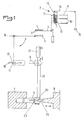
- the process for the automatic manufacture of containers with covering label consists essentially of taking labels 1 individually in a magazine 2 by means of an arm 3 provided with gripping suction cups 4.
- the labels 1 are transferred to two rotary grippers 5 which roll them in the shape of a horn, then the labels thus rolled are gripped by a gripper transfer 6 which inserts them into the matrix 7 of the mold.
- the synthetic material constituting the container is injected into said mold.
- the magazine 2 for receiving the labels 1 essentially consists of a device 9 for guiding the said labels 1 comprising slides 10 for support and lateral support, anterior elastic lateral tabs 11 for retaining the said labels 1 at the extraction end of the device 9 and a means 12 for moving labels 1 under load.
- the means 12 for moving the labels 1 under load is advantageously constituted in the form of a carriage guided on the slides 10 for lateral support and loaded, by means of a cable 14, by a counterweight 15.
- the label package 1 is continuously pressed against the front elastic lateral tabs 11 for holding the labels 1 at the extraction end of the guide device 9.
- the front lateral tabs 11 are preferably formed in the known manner by blades elastic fixed at their upper end on the assembly frame of the slides 10 for lateral support and for label support 1.
- the device is provided with a means 13 for separating the labels when they are removed from the magazine 2 which preferably consists of an air ramp extending transversely above the the extraction end of the magazine 2 and connected to a source of pressurized air.
- a means 13 for separating the labels when they are removed from the magazine 2 which preferably consists of an air ramp extending transversely above the the extraction end of the magazine 2 and connected to a source of pressurized air.
- the arm 3 is provided with gripping suction cups 4 connected to a negative pressure source and is advantageously mounted under the magazine 2 with the possibility of pivoting from a vertical position for extracting the labels 1 from the magazine 2 to a horizontal position for transferring each label flat to the two rotary clamps 5, by actuation by means of a jack 16.
- the rotary clamps 5 are mounted on a support 17 and each actuated, by means of an arm 19, by a rotary actuator 18 integral with said support 17.
- the clamps 5 are arranged eccentrically with respect to the axis rotary actuators of the actuators 18 and effect upon actuation of these last a path in an arc which has the effect of bringing the free ends of the labels 1 in overlap in order to achieve a horn shape.
- the transfer clamp 6 is mounted on a carriage 20, movable by means of a jack 21 on a guide rail 22 between a position opposite the support 17 of the rotary clamps 5 and the die 7 of the mold, said carriage 20 being provided , in addition, of a support 23, for perpendicular movement of the clamp 6 in the direction of the support 17 of the rotary clamps 5, actuated by a jack 24.
- the latter allows movement of the clamp 6 in the direction of the label rolled in horn in order to pinch it at the covering of its ends, then withdraw the support 23 in the starting position before the carriage 20 moves in the direction of the matrix 7 under the action of the jack 21.
- the jack 24 is pressurized again in order to move the clamp 6 with the horn obtained in the direction of the mold matrix and to insert said horn into said matrix 7.
- the different displacements of the arm 3, of the rotary grippers 5 and of the transfer gripper 6, as well as the control of the negative pressurization of the gripping suction cups 4 and of the pressurization of the air ramp forming the means 13 for separating the labels when they are removed from the magazine 2, are commanded and controlled by known detection devices such as probes, photoelectric cells or the like, and the logical succession of these commands and controls is ensured by a programmable automaton.
- the device described above can advantageously be mounted on a chassis (not shown) arranged in the service position above or next to the injection molding machine, retractable by pivoting, by sliding on slides integral with said molding machine, or even by moving away by simple movement on a running gear.
- the die 7 of the mold is provided at its bottom with a peripheral heel 25 for insertion of the corresponding edge of the label 1 .
- the device comprises a number of magazines 2, sampling arms 3, pairs of pliers 5 and transfer pliers 6 corresponding to the number of dies 7 of a multi-cavity mold 8.
- the device comprises a number of magazines 2, sampling arms 3, pairs of pliers 5 and transfer pliers 6 corresponding to the number of dies 7 of a multi-cavity mold 8.
- the labels 1 advantageously have a height at least equal to the height of a container wall between the heel and the heat-sealing area or the first upper shoulder of said container and therefore at less equal to the distance separating the bottom of the peripheral heel from the top of the punch or from the first shoulder of said punch, in the closed position of the mold, the label entirely covering the wall surface of the container.
- the embodiment described above of the matrix 7 and of the labels 1 makes it possible to ensure an application of the lower edge of the label in the bottom of the heel 25 of said matrix 7 and an application of the upper edge against the top of the poin on 26 of the mold or against the first shoulder of the latter, so that an overflow of material during the injection molding of the container towards the outside of the label is prevented with certainty, the upper edge of the label 1 folding back when of said injection outwards against the heat-sealing area or the first shoulder.
- the invention also relates to a container, in particular with a cylindrical section, characterized in that it is provided with a covering label entirely covering its wall from the base to the heat-sealing area or to the first shoulder.
Abstract
Description
La présente invention concerne le domaine de la fabrication de récipients en matière synthétique destinés notamment à l'emballage de produits alimentaires et munis d'étiquettes d'habillage, et a pour objet un procédé de fabrication automatique de tels récipients avec étiquette d'habillage, en particulier des récipients à section cylindrique.The present invention relates to the field of the manufacture of containers made of synthetic material intended in particular for the packaging of food products and provided with covering labels, and relates to an automatic manufacturing process for such containers with covering label, in particular cylindrical section containers.
L invention a également pour objet un dispositif pour la mise en oeuvre de ce procédé.The invention also relates to a device for implementing this method.
Les récipients du type précité sont généralement munis d'étiquettes portant la désignation commerciale de leur contenu ainsi que les constituants de ce dernier.Containers of the aforementioned type are generally provided with labels bearing the commercial description of their contents as well as the constituents of the latter.
Actuellement, la mise en place de ces étiquettes est effectuée, soit, après moulage, au moyen de machines à étiqueter ou par impression, soit par mise en place manuelle des étiquettes dans le moule, avant moulage.Currently, the positioning of these labels is carried out either after molding, using labeling machines or by printing, or by manual positioning of the labels in the mold, before molding.
Dans le premier cas, il est nécessaire de disposer de machines spéciales réalisant l'étiquetage ou l'impression, et une couverture parfaite de toute la surface de la paroi des récipients, qui sont généralement de forme tronconique, est très difficile à obtenir.In the first case, it is necessary to have special machines performing labeling or printing, and perfect coverage of the entire surface of the wall of the containers, which are generally of frustoconical shape, is very difficult to obtain.
Dans le cas d'une mise en place manuelle des étiquettes dans le moule, il existe un important risque d'accident pour l'opérateur réalisant ladite mise en place et le rendement est très faible et incompatible avec une fabrication en grande série.In the case of manual positioning of the labels in the mold, there is a significant risk of accident for the operator carrying out said positioning and the yield is very low and incompatible with mass production.
Il a également été proposé de réaliser une mise en place automatique d'étiquettes dans des moules présentant une forme carrée, rectangulaire ou autre, dans laquelle ladite étiquette comporte une partie de fond et une partie de paroi latérale en plusieurs éléments reliés au fond. Des étiquettes de ce type ne réalisent, cependant, généralement pas une couverture totale de la périphérie de la paroi.It has also been proposed to carry out an automatic placement of labels in molds having a square, rectangular or other shape, in which said label comprises a bottom part and a side wall part made of several elements connected to the bottom. Labels of this type do not, however, generally provide complete coverage of the periphery of the wall.
Enfin, il est également connu par FR-A-2 009 611 un dispositif d'application d'une étiquette, ou analogue, dans la matrice d'un moule, avant injection d'une matière synthétique pour la réalisation de récipients utilisant un mandrin tronconique présentant une surface d'aspiration pour ladite étiquette, qui est enroulée sur ledit mandrin au moyen d un dispositif annexe d'application comportant des rouleaux montés de manière mobile sur un support, l'étiquette étant amenée par un magasin mobile sur ledit support.Finally, it is also known from FR-A-2 009 611 a device for applying a label, or the like, in the die of a mold, before injection of a synthetic material for the production of containers using a mandrel frustoconical having a suction surface for said label, which is wound on said mandrel by means of an annex application device comprising rollers mounted movably on a support, the label being brought by a mobile magazine on said support.
Ce mode de réalisation du dispositif d'application est, cependant, très complexe, notamment en ce qui concerne la réalisation du mandrin tronconique et du dispositif d application.This embodiment of the application device is, however, very complex, in particular with regard to the production of the frustoconical mandrel and the application device.
La présente invention a pour but de pallier ces inconvénients.The present invention aims to overcome these drawbacks.
Elle a, en effet, pour objet un procédé de fabrication automatique de récipients avec étiquette d'habillage, en particulier pour récipients à section cylindrique, caractérisé en ce qu'il consiste essentiellement à prélever des étiquettes individuellement dans un magasin au moyen d'un bras muni de ventouses de préhension, à les transférer à deux pinces rotatives les roulant en forme de cornet, puis à saisir les étiquettes ainsi roulées au moyen d'une pince de transfert les insérant dans la matrice du moule, à fermer le moule de manière à appliquer lesdites étiquettes sur la surface de paroi du moule, puis à injecter la matière synthétique constitutive du récipient dans ce dernier.It has, in fact, for its object a process for the automatic production of containers with a covering label, in particular for cylindrical section containers, characterized in that it essentially consists in picking up labels individually in a store by means of a arm provided with gripping suction cups, to transfer them to two rotary clamps rolling them in the shape of a horn, then to grip the labels thus rolled up by means of a transfer clamp inserting them into the mold of the mold, to close the mold so applying said labels to the wall surface of the mold, then injecting the synthetic material constituting the container into the latter.
L'invention a également pour objet un dispositif pour la mise en oeuvre de ce procédé, caractérisé en ce qu'il est essentiellement constitué par un magasin d'alimentation d'étiquettes, par un bras de prélèvement des étiquettes individuellement hors du magasin et de transfert de ces dernières à deux pinces rotatives de roulage desdites étiquettes en forme de cornet et par une pince de transfert des étiquettes roulées dans la matrice du moule.The invention also relates to a device for implementing this method, characterized in that it essentially consists of a store supply of labels, by an arm for removing the labels individually from the store and transferring the latter to two rotary grippers for rolling said labels in the shape of a horn and by a gripper for transferring the labels rolled in the mold of the mold .
L'invention sera mieux comprise grâce à la description ci-après, qui se rapporte à un mode de réalisation préféré, donné à titre d'exemple non limitatif, et expliqué avec référence aux dessins schématiques annexés, dans lesquels :
- la figure 1 est une vue en élévation latérale du dispositif pour la mise en oeuvre du procédé, et
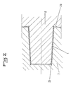
- la figure 2 est une vue en coupe, à plus grande échelle, de la matrice du moule.
- FIG. 1 is a side elevation view of the device for implementing the method, and
- Figure 2 is a sectional view, on a larger scale, of the mold of the mold.
Conformément à l'invention, et comme le montre plus particulièrement, à titre d exemple, la figure 1 des dessins annexés, le procédé de fabrication automatique de récipients avec étiquette d'habillage, en particulier pour récipients à section cylindrique, consiste essentiellement à prélever des étiquettes 1 individuellement dans un magasin 2 au moyen d'un bras 3 muni de ventouses de préhension 4. Les étiquettes 1 sont transférées à deux pinces rotatives 5 qui les roulent en forme de cornet, puis les étiquettes ainsi roulées sont saisies par une pince de transfert 6 qui les insère dans la matrice 7 du moule. Après la fermeture du moule, qui a pour effet d'appliquer les étiquettes 1 sous l'action du poinçon 8 contre la surface de paroi de la matrice 7 du moule, la matière synthétique constitutive du récipient est injectée dans ledit moule.In accordance with the invention, and as shown more particularly, by way of example, FIG. 1 of the appended drawings, the process for the automatic manufacture of containers with covering label, in particular for cylindrical section containers, consists essentially of taking labels 1 individually in a
Le magasin 2 de réception des étiquettes 1 consiste essentiellement en un dispositif 9 de guidage desdites étiquettes 1 comportant des glissières 10 de support et de maintien latéral, des pattes latérales élastiques antérieures 11 de maintien desdites étiquettes 1 à l'extrémité d extraction du dispositif 9 et un moyen 12 de déplacement sous charge des étiquettes 1.The
Le moyen 12 de déplacement sous charge des étiquettes 1 est avantageusement constitué sous forme d'un chariot guidé sur les glissières 10 de maintien latéral et chargé, par l'intermédiaire d'un cable 14, par un contre-poids 15. Ainsi, le paquet d'étiquettes 1 est continuellement pressé contre les pattes latérales élastiques antérieures 11 de maintien des étiquettes 1 à l'extrémité d extraction du dispositif de guidage 9. Les pattes latérales antérieures 11 sont constituées, de préférence, de manière connue, par des lames élastiques fixées à leur extrémité supérieure sur le cadre d'assemblage des glissières 10 de maintien latéral et de support des étiquettes 1.The
Selon une autre caractéristique de l'invention, le dispositif est muni d'un moyen 13 de séparation des étiquettes lors de leur extraction du magasin 2 qui est constitué, de préférence, par une rampe à air s'étendant transversalement au-dessus de l'extrémité d'extraction du magasin 2 et raccordé à une source d'air sous pression. Ainsi, lors de la saisie de l'étiquette d'extrémité au moyen des ventouses 4 du bras 3, l'air, projeté par la rampe formant le moyen 13, favorise le décollement de ladite étiquette 1 du paquet contenu dans le magasin 2.According to another characteristic of the invention, the device is provided with a
Le bras 3 est muni de ventouses de préhension 4 reliées à une source de pression négative et est avantageusement monté sous le magasin 2 avec possibilité de pivotement d'une position verticale d extraction des étiquettes 1 hors du magasin 2 vers une position horizontale de transfert de chaque étiquette à plat vers les deux pinces rotatives 5, par actionnement au moyen d'un vérin 16.The arm 3 is provided with gripping suction cups 4 connected to a negative pressure source and is advantageously mounted under the
Les pinces rotatives 5 sont montées sur un support 17 et actionnées chacune, par l'intermédiaire d'un bras 19, par un vérin rotatif 18 solidaire dudit support 17. Ainsi, les pinces 5 sont disposées de manière excentrée par rapport à l'axe des vérins rotatifs des vérins 18 et effectuent lors de l'actionnement de ces derniers un trajet en arc de cercle qui a pour effet d'amener les extrémités libres des étiquettes 1 en recouvrement afin de réaliser une forme en cornet.The
La pince de transfert 6 est montée sur un chariot 20, déplaçable au moyen d'un vérin 21 sur une glissière de guidage 22 entre une position en face du support 17 des pinces rotatives 5 et la matrice 7 du moule, ledit chariot 20 étant pourvu, en outre, d un support 23, de déplacement perpendiculaire de la pince 6 en direction du support 17 des pinces rotatives 5, actionné par un vérin 24. Ce dernier permet un déplacement de la pince 6 en direction de l'étiquette roulée en cornet afin de réaliser un pincement de celle-ci au niveau du recouvrement de ses extrémités, puis un retrait du support 23 en position de départ avant le déplacement du chariot 20 en direction de la matrice 7 sous l'action du vérin 21. A l'arrivée devant ladite matrice 7, le vérin 24 est remis sous pression afin de déplacer la pince 6 avec le cornet obtenu en direction de la matrice du moule et d'insérer ledit cornet dans ladite matrice 7.The
De manière connue, les différents déplacements du bras 3, des pinces rotatives 5 et de la pince de transfert 6, ainsi que la commande de mise sous pression négative des ventouses de préhension 4 et de mise sous pression de la rampe à air formant le moyen 13 de séparation des étiquettes lors de leur extraction du magasin 2, sont commandés et contrôlés par des dispositifs de détection connus tels que des palpeurs, des cellules photoélectriques ou autres, et la succession logique de cesdits commandes et controles est assurée par un automate programmable.In a known manner, the different displacements of the arm 3, of the
Le dispositif décrit ci-dessus peut avantageusement être monté sur un chassis (non représenté) disposé en position de service au-dessus ou à coté de la machine de moulage par injection, de manière escamotable par pivotement, par coulissement sur des glissières solidaires de ladite machine de moulage, ou encore par éloignement par simple déplacement sur un train de roulement.The device described above can advantageously be mounted on a chassis (not shown) arranged in the service position above or next to the injection molding machine, retractable by pivoting, by sliding on slides integral with said molding machine, or even by moving away by simple movement on a running gear.
Conformément à une autre caractéristique de l'invention, et comme le montre plus particulièrement la figure 2 des dessins annexés, la matrice 7 du moule est pourvue dans son fond d'un talon périphérique 25 d'insertion du bord correspondant de l'étiquette 1.In accordance with another characteristic of the invention, and as shown more particularly in FIG. 2 of the accompanying drawings, the die 7 of the mold is provided at its bottom with a
Selon une variante de réalisation de l'invention, non représentée aux dessins annexés, le dispositif comporte un nombre de magasins 2, de bras de prélèvement 3, de paires de pinces 5 et de pinces de transfert 6 correspondant au nombre de matrices 7 d un moule mult-icavités 8. Ainsi, l'alimentation automatique d'un moule multi-cavités est également rendu possible.According to an alternative embodiment of the invention, not shown in the accompanying drawings, the device comprises a number of
En outre, selon une autre caractéristique de l'invention, les étiquettes 1 présentent avantageusement une hauteur au moins égale à la hauteur d'une paroi de récipient comprise entre le talon et la plage de thermoscellage ou le premier épaulement supérieur dudit récipient et donc au moins égale à la distance séparant le fond du talon périphérique du haut du poin on ou du premier épaulement dudit poinçon, en position de fermeture du moule, l'étiquette recouvrant entièrement la surface de paroi du récipient.In addition, according to another characteristic of the invention, the labels 1 advantageously have a height at least equal to the height of a container wall between the heel and the heat-sealing area or the first upper shoulder of said container and therefore at less equal to the distance separating the bottom of the peripheral heel from the top of the punch or from the first shoulder of said punch, in the closed position of the mold, the label entirely covering the wall surface of the container.
Le mode de réalisation décrit ci-dessus de la matrice 7 et des étiquettes 1 permet d assurer une application du bord inférieur de l'étiquette dans le fond du talon 25 de ladite matrice 7 et une application du bord supérieur contre le haut du poin on 26 du moule ou contre le premier épaulement de ce dernier, de sorte qu'un débordement de matière lors du moulage par injection du récipient vers l'extérieur de l'étiquette est empêché avec certitude, le bord supérieur de l étiquette 1 se repliant lors de ladite injection vers l'extérieur contre la plage de thermoscellage ou le premier épaulement. Ainsi, il est possible d assurer de manière certaine un recouvrement total de la paroi du récipient par l'étiquette 1 jusqu'à la plage de thermoscellage ou jusqu'au premier épaulement.The embodiment described above of the matrix 7 and of the labels 1 makes it possible to ensure an application of the lower edge of the label in the bottom of the
L'invention a également pour objet un récipient, en particulier à section cylindrique, caractérisé en ce qu'il est pourvu d'une étiquette d'habillage recouvrant entièrement sa paroi de la base jusqu'à la plage de thermoscellage ou au premier épaulement.The invention also relates to a container, in particular with a cylindrical section, characterized in that it is provided with a covering label entirely covering its wall from the base to the heat-sealing area or to the first shoulder.
Bien entendu, l'invention n'est pas limitée au mode de réalisation décrit et représenté aux dessins annexés. Des modifications restent possibles, notamment du point de vue de la constitution des divers éléments ou par substitution d'équivalents techniques, sans sortir pour autant du domaine de protection de l'invention.Of course, the invention is not limited to the embodiment described and shown in the accompanying drawings. Modifications remain possible, in particular from the point of view of the constitution of the various elements or by substitution of technical equivalents, without thereby departing from the scope of protection of the invention.
Claims (13)
Applications Claiming Priority (2)
| Application Number | Priority Date | Filing Date | Title |
|---|---|---|---|
| FR8802674 | 1988-02-29 | ||
| FR8802674A FR2627744B1 (en) | 1988-02-29 | 1988-02-29 | METHOD FOR AUTOMATICALLY MANUFACTURING CONTAINERS WITH COVERING LABEL, PARTICULARLY FOR CONTAINERS WITH CYLINDRICAL SECTION AND DEVICE FOR CARRYING OUT SAID METHOD |
Publications (3)
| Publication Number | Publication Date |
|---|---|
| EP0331596A2 true EP0331596A2 (en) | 1989-09-06 |
| EP0331596A3 EP0331596A3 (en) | 1991-01-23 |
| EP0331596B1 EP0331596B1 (en) | 1994-04-06 |
Family
ID=9363860
Family Applications (1)
| Application Number | Title | Priority Date | Filing Date |
|---|---|---|---|
| EP19890440015 Expired - Lifetime EP0331596B1 (en) | 1988-02-29 | 1989-02-22 | Process for the automatic manufacture of containers with coating labels, in particular for circular containers, and a device for carrying out this process |
Country Status (3)
| Country | Link |
|---|---|
| EP (1) | EP0331596B1 (en) |
| DE (2) | DE68914311T2 (en) |
| FR (1) | FR2627744B1 (en) |
Cited By (4)
| Publication number | Priority date | Publication date | Assignee | Title |
|---|---|---|---|---|
| FR2659948A1 (en) * | 1990-03-21 | 1991-09-27 | Tulipia | Device for feeding covering sheets, for a machine for moulding containers |
| FR2762295A1 (en) * | 1997-04-18 | 1998-10-23 | Potier Muller Colette | METHOD AND DEVICE FOR MANUFACTURING A CONTAINER EQUIPPED WITH A LABEL |
| CN100390025C (en) * | 2005-01-31 | 2008-05-28 | 黄胜昌 | Label automatic-conveying device |
| WO2015060713A1 (en) * | 2013-10-25 | 2015-04-30 | Polymac B.V. | Method and device for arranging a label in a mould |
Families Citing this family (3)
| Publication number | Priority date | Publication date | Assignee | Title |
|---|---|---|---|---|
| DE102005004396A1 (en) * | 2005-01-31 | 2006-08-03 | Hekuma Gmbh | Label placement onto inner surface of cylindrical injection molding tool involves alignment of label on holding mandrel then moves to molding tool where label is transferred to tool wall and held in position |
| CN102785804B (en) * | 2012-08-24 | 2015-01-14 | 张家港市天奇自动化机械制造有限公司 | Automatic labeling device |
| CN105501587B (en) * | 2015-12-23 | 2018-07-17 | 惠州市杨森工业机器人有限公司 | In-mold label system |
Citations (4)
| Publication number | Priority date | Publication date | Assignee | Title |
|---|---|---|---|---|
| FR2009611A1 (en) * | 1968-05-29 | 1970-02-06 | Sommer Fritz | |
| CH556728A (en) * | 1970-07-17 | 1974-12-13 | Airfix Ind Ltd | MOLDING MACHINE. |
| CH638718A5 (en) * | 1979-03-28 | 1983-10-14 | Sandherr Max Ag | Process for producing a plastic container |
| US4645193A (en) * | 1984-05-30 | 1987-02-24 | Richard R. Walton | Fabric pickup and the like |
Family Cites Families (1)
| Publication number | Priority date | Publication date | Assignee | Title |
|---|---|---|---|---|
| US3509721A (en) * | 1969-03-28 | 1970-05-05 | John M Crawford | Multiple motor hydraulic drive system |
-
1988
- 1988-02-29 FR FR8802674A patent/FR2627744B1/en not_active Expired - Fee Related
-
1989
- 1989-02-22 DE DE1989614311 patent/DE68914311T2/en not_active Expired - Lifetime
- 1989-02-22 EP EP19890440015 patent/EP0331596B1/en not_active Expired - Lifetime
- 1989-02-22 DE DE1989440015 patent/DE331596T1/en active Pending
Patent Citations (4)
| Publication number | Priority date | Publication date | Assignee | Title |
|---|---|---|---|---|
| FR2009611A1 (en) * | 1968-05-29 | 1970-02-06 | Sommer Fritz | |
| CH556728A (en) * | 1970-07-17 | 1974-12-13 | Airfix Ind Ltd | MOLDING MACHINE. |
| CH638718A5 (en) * | 1979-03-28 | 1983-10-14 | Sandherr Max Ag | Process for producing a plastic container |
| US4645193A (en) * | 1984-05-30 | 1987-02-24 | Richard R. Walton | Fabric pickup and the like |
Cited By (6)
| Publication number | Priority date | Publication date | Assignee | Title |
|---|---|---|---|---|
| FR2659948A1 (en) * | 1990-03-21 | 1991-09-27 | Tulipia | Device for feeding covering sheets, for a machine for moulding containers |
| FR2762295A1 (en) * | 1997-04-18 | 1998-10-23 | Potier Muller Colette | METHOD AND DEVICE FOR MANUFACTURING A CONTAINER EQUIPPED WITH A LABEL |
| WO1998047685A1 (en) * | 1997-04-18 | 1998-10-29 | Potier-Muller, Colette | Method and device for making a container provided with a label |
| US6790400B1 (en) | 1997-04-18 | 2004-09-14 | Paul A. Muller | Method and device for making a container provided with a label |
| CN100390025C (en) * | 2005-01-31 | 2008-05-28 | 黄胜昌 | Label automatic-conveying device |
| WO2015060713A1 (en) * | 2013-10-25 | 2015-04-30 | Polymac B.V. | Method and device for arranging a label in a mould |
Also Published As
| Publication number | Publication date |
|---|---|
| FR2627744B1 (en) | 1991-12-06 |
| FR2627744A1 (en) | 1989-09-01 |
| EP0331596A3 (en) | 1991-01-23 |
| DE68914311T2 (en) | 1994-11-17 |
| DE331596T1 (en) | 1990-05-03 |
| DE68914311D1 (en) | 1994-05-11 |
| EP0331596B1 (en) | 1994-04-06 |
Similar Documents
| Publication | Publication Date | Title |
|---|---|---|
| EP1009610B1 (en) | Method and device for making a container provided with a label | |
| BE1005832A5 (en) | Method and apparatus for thermoforming and extraction of objects equipped with a hollow bottom band from a thermoplastic material. | |
| FR2679818A1 (en) | METHOD AND DEVICE FOR CUTTING PLATES OF FLAT GLASS. | |
| CA1074070A (en) | Apparatus designed for protecting receptades with sectional thermoplastic sheathing | |
| EP0559512B1 (en) | Device for closing receptacles by heat-sealing of covers and plant comprising such a device | |
| EP0331596B1 (en) | Process for the automatic manufacture of containers with coating labels, in particular for circular containers, and a device for carrying out this process | |
| EP0069011B1 (en) | Apparatus for applying and centering a thermoplastics sleeve around an article by means of a vertical member provided with a floating mandrel | |
| EP1523404B1 (en) | Device and method for thermoforming an object having a back draft portion | |
| CH543361A (en) | Device for shaping a sheet and use of this device | |
| EP0373091A1 (en) | Device for and method of bulk-feeding a machine for raising and aligning containers coupled to a bottling line | |
| EP0033670B1 (en) | Method and apparatus for removing soft cheese from a mould | |
| BE1012756A3 (en) | Method and device for the production of brushes. | |
| FR2729376A1 (en) | Pastry or other food tray distributor | |
| EP0249550B1 (en) | Apparatus for preforming and transferring a label in a machine for thermoforming recipients | |
| EP0130092B1 (en) | Method and apparatus for automatically loading and/or unloading bobbins | |
| FR2501624A1 (en) | PROCESS FOR GROUPING, ORIENTATION AND PACKAGING OF OBJECTS AND INSTALLATION FOR CARRYING OUT SAID METHOD | |
| EP0057144A2 (en) | Machine for packaging cylindrically shaped objects in blanks cut from thermoplastic webs | |
| FR2631924A1 (en) | Automatic method for installing a stretchable sleeve tube for labelling plastic or metal packages and device for implementing this method | |
| WO2020254464A1 (en) | Device for gripping products, and method for conveying within an industrial production line | |
| EP0028219B1 (en) | Automatic loader apparatus for loading bags in rotary bag-filling machines | |
| EP0519142B1 (en) | Apparatus for feeding and depositing a flexible label into a mould onto a moulded object | |
| EP0562197B1 (en) | Method and device for palletizing parcels | |
| EP1698585A1 (en) | Automatic machine for applying glass stoppers onto bottles | |
| FR2673922A1 (en) | Method and device for palletising parcels | |
| FR2471851A1 (en) | Appts. for automatic manipulation of tubular packaging film - with cam mechanisms interchangeable to suit different sleeve or pack formats |
Legal Events
| Date | Code | Title | Description |
|---|---|---|---|
| PUAI | Public reference made under article 153(3) epc to a published international application that has entered the european phase |
Free format text: ORIGINAL CODE: 0009012 |
|
| AK | Designated contracting states |
Kind code of ref document: A2 Designated state(s): BE DE GB IT NL |
|
| ITCL | It: translation for ep claims filed |
Representative=s name: ING. FISCHETTI WEBER |
|
| TCNL | Nl: translation of patent claims filed | ||
| GBC | Gb: translation of claims filed (gb section 78(7)/1977) | ||
| DET | De: translation of patent claims | ||
| PUAL | Search report despatched |
Free format text: ORIGINAL CODE: 0009013 |
|
| AK | Designated contracting states |
Kind code of ref document: A3 Designated state(s): BE DE GB IT NL |
|
| 17P | Request for examination filed |
Effective date: 19910311 |
|
| 17Q | First examination report despatched |
Effective date: 19920630 |
|
| RTI1 | Title (correction) | ||
| GRAA | (expected) grant |
Free format text: ORIGINAL CODE: 0009210 |
|
| AK | Designated contracting states |
Kind code of ref document: B1 Designated state(s): BE DE GB IT NL |
|
| PG25 | Lapsed in a contracting state [announced via postgrant information from national office to epo] |
Ref country code: IT Free format text: LAPSE BECAUSE OF FAILURE TO SUBMIT A TRANSLATION OF THE DESCRIPTION OR TO PAY THE FEE WITHIN THE PRESCRIBED TIME-LIMIT;WARNING: LAPSES OF ITALIAN PATENTS WITH EFFECTIVE DATE BEFORE 2007 MAY HAVE OCCURRED AT ANY TIME BEFORE 2007. THE CORRECT EFFECTIVE DATE MAY BE DIFFERENT FROM THE ONE RECORDED. Effective date: 19940406 Ref country code: NL Effective date: 19940406 Ref country code: GB Effective date: 19940406 |
|
| REF | Corresponds to: |
Ref document number: 68914311 Country of ref document: DE Date of ref document: 19940511 |
|
| NLV1 | Nl: lapsed or annulled due to failure to fulfill the requirements of art. 29p and 29m of the patents act | ||
| GBV | Gb: ep patent (uk) treated as always having been void in accordance with gb section 77(7)/1977 [no translation filed] |
Effective date: 19940406 |
|
| PLBE | No opposition filed within time limit |
Free format text: ORIGINAL CODE: 0009261 |
|
| STAA | Information on the status of an ep patent application or granted ep patent |
Free format text: STATUS: NO OPPOSITION FILED WITHIN TIME LIMIT |
|
| PG25 | Lapsed in a contracting state [announced via postgrant information from national office to epo] |
Ref country code: BE Effective date: 19950228 |
|
| 26N | No opposition filed | ||
| BERE | Be: lapsed |
Owner name: GIZEH S.A.R.L. Effective date: 19950228 |
|
| PGFP | Annual fee paid to national office [announced via postgrant information from national office to epo] |
Ref country code: DE Payment date: 19990422 Year of fee payment: 11 |
|
| PG25 | Lapsed in a contracting state [announced via postgrant information from national office to epo] |
Ref country code: DE Free format text: LAPSE BECAUSE OF NON-PAYMENT OF DUE FEES Effective date: 20001201 |