EP0331502A2 - Focus control apparatus and methods - Google Patents
Focus control apparatus and methods Download PDFInfo
- Publication number
- EP0331502A2 EP0331502A2 EP89302118A EP89302118A EP0331502A2 EP 0331502 A2 EP0331502 A2 EP 0331502A2 EP 89302118 A EP89302118 A EP 89302118A EP 89302118 A EP89302118 A EP 89302118A EP 0331502 A2 EP0331502 A2 EP 0331502A2
- Authority
- EP
- European Patent Office
- Prior art keywords
- lens
- signal
- predetermined frequency
- frequency component
- change
- Prior art date
- Legal status (The legal status is an assumption and is not a legal conclusion. Google has not performed a legal analysis and makes no representation as to the accuracy of the status listed.)
- Granted
Links
Images


Classifications
-
- H—ELECTRICITY
- H04—ELECTRIC COMMUNICATION TECHNIQUE
- H04N—PICTORIAL COMMUNICATION, e.g. TELEVISION
- H04N23/00—Cameras or camera modules comprising electronic image sensors; Control thereof
- H04N23/60—Control of cameras or camera modules
- H04N23/67—Focus control based on electronic image sensor signals
- H04N23/673—Focus control based on electronic image sensor signals based on contrast or high frequency components of image signals, e.g. hill climbing method
-
- H—ELECTRICITY
- H04—ELECTRIC COMMUNICATION TECHNIQUE
- H04N—PICTORIAL COMMUNICATION, e.g. TELEVISION
- H04N23/00—Cameras or camera modules comprising electronic image sensors; Control thereof
- H04N23/60—Control of cameras or camera modules
- H04N23/63—Control of cameras or camera modules by using electronic viewfinders
- H04N23/633—Control of cameras or camera modules by using electronic viewfinders for displaying additional information relating to control or operation of the camera
- H04N23/635—Region indicators; Field of view indicators
Definitions
- This invention relates to focus control apparatus and methods, and in particular to focus control apparatus and methods used in contrast detecting systems of video cameras.
- an autofocusing system of the kind used in a video camera a system has been proposed for obtaining a correct focus position that involves what is called peak detecting control.
- One such autofocusing system is based on the finding that selected frequency components in the video signal, excluding the DC component, become a maximum at the correct focus position.
- the frequency components (excluding the DC component) in the video signal are integrated and form so-called evaluation value data, and the lens is then moved to the position at which the evaluation value data is a maximum.
- An example of such a system is described in Japanese Patent Application No. 62-146 628.
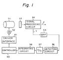
- Figure 1 of the accompanying drawings represents an example of such an autofocusing system, in which a lens 51 is moved by a lens drive motor 52, and an image obtained through the lens 51 is picked up by a CCD image pickup device 53.
- the output of the CCD image pickup device 53 is supplied to a signal processing circuit 54 and a luminance signal Y is extracted.
- the luminance signal Y is fed through a bandpass filter 55 to a detecting circuit 56 whose output is supplied to an analog-to-digital (A/D) converter 57.
- the digital output of the A/D converter 57 is supplied to an integrating circuit 58, in which the output of the A/D converter 57 is integrated over a predetermined area.
- the output of the integrating circuit 58 then constitutes the evaluation value data.
- the evaluation value data is supplied to a controller 60 that produces a drive signal which is supplied to the lens drive motor 52 through a driver interface unit 61.
- the controller 60 controls the position of the lens 51 by moving it to the position at which the evaluation value data, which is the output from the integrating circuit 58, becomes a maximum.
- this is peak detecting control being used in an autofocusing system.
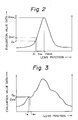
- Such peak detecting control assumes that the relation between the lens position and the evaluation value data can be described by a curve, such as that shown in Figure 2 of the accompanying drawings.
- evaluation value data Dn that is obtained at a lens position ln and evaluation value data Dn+1 that is obtained at a lens position ln+1, which is a subsequent continuous lens position relative to the lens position ln are compared while moving the lens 51 in one direction.
- the lens 51 is moved until the evaluation value data Dn obtained at the lens position ln is smaller than the evaluation value data Dn+1 obtained at the subsequent continuous lens position ln+1.
- the peak detecting control is operated to discriminate whether the evaluation value data at the two continuous lens positions have changed from increasing in value to decreasing in value while moving the lens in one direction, as explained above, there is the distinct possibility that the concave/convex portion, sometimes called a "false peak", will be erroneously thought to be the lens position at which the evaluation value data is a maximum.
- a predetermined threshold value is provided when discriminating whether the evaluation value data at the two successive lens positions changes from increasing to decreasing. In this way, a check is made to determine whether the difference between the evaluation value data at the two lens positions has been reduced by the predetermined threshold value. If such difference exceeds the predetermined threshold value and changes in the decreasing direction, it is determined that the lens has actually passed through the lens position at which the evaluation value data is a maximum.
- the position of the lens at which the evaluation value data is detected as a maximum can overrun or overshoot the actual lens position at which the evaluation value data is the maximum. Therefore, a process must be performed to return the position of the lens by only the overrun amount.
- this overrun amount increases when rotating the lens drive motor 52 of Figure 1 at a high speed. Therefore, with a view to reducing the overrun amount, it is desirable to reduce the speed of rotation of the drive motor when executing peak detecting control; however, when the lens drive motor is operated at a low speed, the control speed and autofocus system response is slow.
- the evaluation value data will be detected as having passed through the maximum value only when the evaluation value data has actually exceeded the maximum value and has decreased to the threshold value or less; consequently, the overrun amount will be greater.
- the focus control apparatus may be characterised by features wherein the predetermined frequency component in the video signal can be sampled at points of at least first to third continuous lens positions and a first gradient indicative of a change in value of the predetermined frequency component in the video signal for a change in lens position between the first and second lens position points is obtained; a second gradient indicative of a change in value of the predetermined frequency component in the video signal for a change in lens position between the second and third lens positions is obtained from the signal containing the predetermined frequency component from the video signal sampled at the second lens position point and the signal of the predetermined frequency component in the video signal sampled at the third lens position point; the longitudinal moving speed of the lens is controlled in accordance with changes in the first and second gradients.
- focus control apparatus for a video camera in which a component of a video signal is maximised for performing focus control, the apparatus comprising: means for extracting a signal having a predetermined frequency component from a video signal; means for moving a position of a lens of the camera; means for sampling the signal of predetermined frequency component extracted from the video signal at continuous, successive at least first, second, and third lens positions; means for determining a first gradient indicative of a change in value of the signal of predetermined frequency component for a change in lens position between said first and second lens positions from the signal of the predetermined frequency component sampled at the first lens position and the signal of predetermined frequency component sampled at the second lens position; means for determining a second gradient indicative of a change in value of the signal of predetermined frequency component for a change in lens position between said second and third lens positions from the signal of the predetermined frequency component sampled at the second lens position and the signal of predetermined frequency component sampled at the third lens position; and means for controlling the speed of movement of
- a method of focus control for a video camera comprising the steps of: detecting the maximum value of a luminance component in an image pickup signal; adjusting the rotational position of a focusing ring of an image pickup lens on the basis of the result of the detection; and when said maximum value is detected, rotating said focusing ring at a low speed for a predetermined time to discriminate an increasing direction of the luminance component from a start point and, thereafter, until said luminance component exceeds a predetermined level, rotating the focusing ring at a high speed, and rotating the focusing ring at a low speed when said level is set to at least the predetermined level.
- a method of focus control for a video camera wherein a video signal level from the camera is maximised by movement of the lens through continuous positions to the in-focus position, the method comprising the steps of: extracting a signal having a predetermined frequency component from the video signal; sampling the extracted signal at at least three successive points corresponding to three respective lens positions; deriving a first gradient indicative of a change in value between said extracted signal at a first sample point and a second sample point; deriving a second gradient indicative of a change in value between said extracted signal at said second sample point and a third sample point; comparing the first and second gradients; and controlling the speed of movement of the lens in response to the comparison.
- a focus control system for automatically setting the lens of a video camera to an in-focus position, the system comprising: an image pickup element for receiving an image through the lens of the video camera and producing an output signal therefrom; a video signal processing circuit for receiving said output signal from said image pickup element and producing a video signal including at least a luminance signal and a chrominance signal; bandpass filter means for receiving said luminance signal and extracting a signal therefrom having predetermined frequency components; means for moving the lens over predetermined lens travel limits; means for sampling the extracted signal at at least three sample points corresponding to three respective continuous lens locations; means for producing a first gradient indicative of a change in value of the sampled extracted signal between a first sample point and a second sample point, and for producing a second gradient indicative of a change in value of the sampled extracted signal between said second sample point and a third sample point; means for comparing said first and second gradients and producing an output indicative of the comparison; and means for controlling the speed of said means for moving the
- the preferred embodiment of the present invention provides a focus control apparatus in which the lens drive motor is driven at a high speed until the evaluation value data approaches a maximum value and, as the evaluation value data approaches the maximum value, the driving motor is driven at a low speed, thereby allowing the control speed to be high and at the same time reducing the amount of lens overshoot.
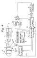
- a lens 1 is mounted for rotation in either of the directions of arrows a and b by a lens drive motor 2 interacting with a focus ring 1a, so that by use of suitable mechanical elements (not shown), the lens 1 is moved longitudinally in either of the directions of arrows c and d , and the focus position is thereby controlled. More specifically, when the lens 1 is rotated in the direction of the arrow a by the drive motor 2, the lens 1 is moved in the direction of the arrow c , and is focused to the near distance. When the lens 1 is rotated in the direction of the arrow b , the lens 1 is moved in the direction of the arrow d and is focused to the far distance.
- the image obtained through the lens 1 is picked up by a CCD image pickup device 3, and an output signal of the CCD image pickup device 3 is supplied to a signal processing circuit 4.
- the signal processing circuit 4 operates on the image signal to extract a luminance signal Y and a chrominance or chroma signal C, and it typically includes a processing circuit, a colour encoder and the like.
- the luminance signal Y extracted by the signal processing circuit 4 is supplied to bandpass filters 5A and 5B.
- the passband frequency of the bandpass filter 5A is set from 100 kHz to 4 MHz
- the passband frequency of the bandpass filter 5B is set from 500 kHz to 4 MHz.
- the switching circuit 6 is controlled in accordance with the image of an object by a switch control signal SC from a controller 10. For example, in the case of an object of strong contrast, the output of the bandpass filter 5B is selected and in the case of an object of weak contrast, the output of the bandpass filter 5A is selected.
- the output of the switching circuit 6 is supplied to a detecting circuit 7 where the level of the output from one of the bandpass filters 5A or 5B is detected.
- the output of the detecting circuit 7 is supplied to an analog-to-digital (A/D) converter 8 wherein the portion of the luminance signal Y having a predetermined level and a predetermined frequency component is digitised.
- A/D analog-to-digital
- the output of the A/D converter 8 is supplied to an integrating circuit 9 that also receives an integration area control signal SA supplied from the controller 10.
- the digital data of known level and predetermined frequency component derived from the luminance signal Y is integrated by the integrating circuit 9 over an area that is designated by the integration area control signal SA and is supplied as evaluation value data D to the controller 10.
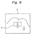
- Figure 9 is a pictorial schematic representation of a typical scene A as might be seen by a video camera, and the area over which the signal is to be integrated is shown at B.
- the controller 10 controls the position of the lens 1 in accordance with the peak detecting control method by using the evaluation value data D from the integrating circuit 9, thereby obtaining the proper focus position of the lens 1.
- the driving signal for the lens drive motor 2 is supplied from the controller 10 and fed through a driver interface 11 to the lens drive motor 2.
- a counter or back electromotive force (EMF) signal is typically generated by the lens drive motor 2 in association with its rotation, and the counter electromotive force signal is supplied to the controller 10 through the driver interface 11 as a frequency generator (FG) signal used by the controller 10 to detect the rate of rotation of the lens drive motor 2.
- the FG signals are counted over a predetermined time and the rotational speed of the lens drive motor 2 is detected based on the count value of the FG signals.
- the detected rotational speed and the derived rotational speed are compared and the driving voltage according to the results of the comparison is provided to the drive motor 2 through the driver interface 11.
- the FG signal can be also obtained by optical means or magnetic means using any of several well-known approaches.
- a potentiometer 12 is mechanically connected to detect the longitudinal position of the lens 1 and the potentiometer 12 is electrically connected to the controller 10.
- a diaphragm or iris opening detecting device 13 detects the extent or degree of the iris opening and a signal representing this is supplied to the controller 10.
- a coefficient for the evaluation value data D is set by the outputs of the potentiometer 12 and the iris opening detecting device 13.
- a reflective film 15 is attached to a part of the outer periphery of the barrel of the lens 1, and a light emitting diode 16 and a photodiode 17 are provided to cooperate with the reflective film 15.
- the output of the photodiode 17 is also supplied to the controller 10.
- the reflective film 15 is arranged to correspond to a region wherein the lens 1 lies within a movable range.
- the region where the lens 1 is out of the movable range corresponds to the remainder of the lens barrel not covered by the light reflective tape 15, an area forming a non-reflective portion 18.
- the lens 1 When the lens 1 lies within the movable range, the output of the light emitting diode 16 is reflected by the reflective film 15, and the reflected light is received by the photodiode 17 and an output signal is produced.
- the lens 1 When the lens 1 is moved so that the edge of the reflective tape 15 is out of view of the light emitting diode 16, the light from the light emitting diode 16 irradiates the non-reflective portion 18 of the lens barrel, so that no output is obtained from the photodiode 17.
- the focusing of the lens 1 can be performed by using the evaluation value data D obtained by integrating the data of the level-limited, predetermined-frequency component of the luminance signal Y over a predetermined area, as shown for example at B in Figure 9. More specifically, when measuring a distribution of the spectrum components and the corresponding intensity in which the focusing state extends from the complete out-of focus state to the in-focus state and back again to the out-of focus state, in the out-of focus state the spectrum component exists on the low-frequency side and its magnitude is small. As the lens approaches the in-focus state, the spectrum component deviates to the high-frequency side and its magnitude also increases. As a result of this, all of the frequency components, excluding the DC component, in the video signal are integrated, and the resultant data can be used as the focus evaluation value data D obtained from the output of the integrating circuit 9.
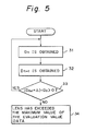
- the lens position at which the evaluation value data D becomes maximum is searched for in accordance with a peak detecting control method, as represented in Figure 5.
- the lens position at which the evaluation value data D becomes maximum is set to be the in-focus position.
- evaluation value data Dn is obtained while moving the lens 1 in one direction by the lens drive motor 2, in a step 31.
- evaluation value data Dn+1 which is continuous to the data Dn, is obtained in a step 32 by continuing to drive the lens in the same direction.
- the difference between the evaluation value data Dn and Dn+1 is calculated in a step 33 and a check is made to determine whether the evaluation value data difference has exceeded a predetermined threshold value ⁇ and has begun to decrease.
- the processing routine returns to the step 31, and the driving of the lens drive motor 2 continues.
- the difference between the evaluation value data Dn and Dn+1 is found to exceed the predetermined threshold value ⁇ and the evaluation value data Dn+1 is smaller than the evaluation value data Dn, it is determined in a step 34 that the lens has gone past the point resulting in the maximum of the evaluation value data.
- the threshold value ⁇ is provided to allow for the case where a so-called concave/convex portion or false peak occurs in the curve of the lens position versus the evaluation value data.
- the rotating speed of the lens drive motor 2 is controlled in accordance with the curve indicative of the relationship between the change in lens position and the change in evaluation value data. That is, when the lens position is distant from the maximum value of the evaluation value data, the lens drive motor 2 is rotated at a high speed. When the lens position approaches the maximum value of the evaluation value data, the speed of rotation of the lens drive motor 2 is slowed.
- the peak detecting control can be performed at a high speed and yet the overrun amount, when it is detected that the lens has assumed a position that exceeds the position that would result in the maximum value of the evaluation value data, can be minimised.
- the motor speed is set on the basis of the FG signal derived as described above. More specifically, according to an embodiment of the present invention, the rotating speed of the lens drive motor 2 has been set on the basis of the ratio of the gradient of the curve plotting the change in the lens position versus the change in evaluation value data at continuous, successive lens positions. When the lens position approaches the maximum value of the evaluation value data, the curve representative of the relation between the change in lens position and the change in evaluation value data gradually becomes flat.
- Figure 7 is a flowchart of a method of performing the arithmetic operation based on the equation (3).
- the differences ⁇ MAX0 and ⁇ MAX1 between the continuous evaluation value data and the movement distances ⁇ step1 and ⁇ step0 are first obtained and n is initialised in a step 41.
- the calculation process of the equation (3) is executed and the value of A is obtained in a step 42.
- a step 43 a check is made to determine whether the value of A is 0 or less, and when the value of A is not 0 or less, n is increased by one in a step 44 and the processing routine returns to the step 42.
- a control voltage for the lens drive motor 2 corresponding to the value of n at that moment is produced in a step 45.
- the lens drive motor 2 is rotated at a low speed as the lens position approaches the maximum value of the evaluation value data, so that the amount of overrun or overshoot of the lens position is effectively reduced.
- the luminance signal Y of the baseband signal extracted by the signal processing circuit 4 from the image pickup signal output from the CCD image pickup device 3 is supplied to the bandpass filter 5A.
- signal components having a frequency falling between 100 kHz and 4MHz are extracted from the luminance signal Y by the bandpass filter 5A.
- the luminance signal components between 100 kHz and 4MHz are converted into digital signals by the A/D converter 8, and the data of all of the focus detecting points of one picture plane are integrated by the integrating circuit 9.
- an integration value y1 is obtained in the controller 10.
- the controller 10 supplies a low-speed drive signal to the lens drive motor 2 upon activation, so that the focusing ring 1a is slightly rotated in both directions at a low speed.
- the controller 10 discriminates whether the integration value increases when the focusing ring 1a is rotated in one of the two directions, and this discriminating operation may be completed in 0.5 s.
- the focusing ring 1a is rotated in the increasing direction of the integration value under the control of the controller 10. In the example of Figure 8, this is in the direction of an arrow U to increase the distance of the focus position.
- a check is performed to determine whether the integration value has exceeded the threshold value Dsp, and the motor rotating speed is controlled accordingly. For instance, in the example of Figure 8, when 0.5 s. has passed from the activation, assuming that the integration value is set to a value y2 lower than the threshold value Dsp, the controller 10 supplies a high speed drive signal to the lens drive motor 2, thereby rotating the focusing ring 1a at a high speed.
- the controller 10 supplies a low speed drive signal to the lens drive motor 2, thereby rotating the focusing ring 1a at a low speed.
- the integration value is set to the maximum value y0 corresponding to the distance of 2 metres.
- the controller 10 determines that the integration value y0 at the distance of 2 metres is the maximum value and it is determined that the position corresponding to 2 metres is the in-focus point. The focusing ring 1a is thus returned to the position corresponding to the distance of 2 metres at a low speed and is then stopped.
- the focusing ring 1a is slightly rotated forwards and backwards at predetermined intervals.
- the integration values y- and y+ of the luminance components at the focus positions just before and after the position of 2 metres less than y0 are detected, thereby confirming that the integration value y0 at the distance of 2 metres is the maximum value. It is thus decided that the in-focus state is continuing.
- the focusing ring 1a is rotated at a low speed.
- the circuit When it is detected by the in-focus discrimination that the lens position is no longer in the in-focus state, the circuit is again actived and the operation to search for the maximum value of the integration value of the luminance components as described above is executed.
- the focusing ring 1a is rotated at a slow speed for 0.5 s. which is necessary to discriminate the correct rotational direction of the focusing ring 1a. Therefore, the switching of the rotational direction upon activation or the like is smoothly executed by the small motion at the low speed. After the lapse of 0.5 s. at the low luminance level in the case of the threshold value Dsp or less where the possibility of the actual in-focus point is low, the focusing ring 1a is rotated at a high speed. Thus, the focus position approaches the in-focus point in a short time.
- the rotation of the focusing ring 1a smoothes out and the focus position approaches the in-focus point in a short time.
- fluctuations of the in-focus point can be tracked more accurately.
- the speed of the lens drive motor is determined based upon the ratio of the gradient of the curve indicative of the relationship between the change in lens position and the change in evaluation value data at the continuous lens positions between the two end positions of the lens.
- the driving motor is rotated at a high speed and when the lens position approaches the maximum value of the evaluation value data, the driving motor is rotated at a low speed.
- peak detecting control can be performed at a high speed. The lens overrun amount when it is detected that the lens position has passed the point corresponding to the maximum value of the evaluation value data can be minimised by the peak detecting control.
- the rotational speed of the focusing ring is controlled to the optimum state on the basis of the result of the detection of the integrated value of the luminance component in the image pickup signal, there are advantages in that the motion of the focusing ring becomes smooth, the focus position approaches the in-focus point in a short time, and the tracking capability for following fluctuations in the in-focus point is improved.
Abstract
Description
- This invention relates to focus control apparatus and methods, and in particular to focus control apparatus and methods used in contrast detecting systems of video cameras.
- In an autofocusing system of the kind used in a video camera, a system has been proposed for obtaining a correct focus position that involves what is called peak detecting control. One such autofocusing system is based on the finding that selected frequency components in the video signal, excluding the DC component, become a maximum at the correct focus position. The frequency components (excluding the DC component) in the video signal are integrated and form so-called evaluation value data, and the lens is then moved to the position at which the evaluation value data is a maximum. An example of such a system is described in Japanese Patent Application No. 62-146 628. In that type of autofocusing system, in order to move the lens to the focus position at which the evaluation value data becomes a maximum, several processes must be executed in which the evaluation value data at the front and rear lens positions are compared and a discrimination made, in order to determine the point at which the evaluation value data changes from increasing to decreasing with change in position; such processes are called peak detecting control.
- Figure 1 of the accompanying drawings represents an example of such an autofocusing system, in which a
lens 51 is moved by alens drive motor 52, and an image obtained through thelens 51 is picked up by a CCDimage pickup device 53. The output of the CCDimage pickup device 53 is supplied to asignal processing circuit 54 and a luminance signal Y is extracted. The luminance signal Y is fed through abandpass filter 55 to a detectingcircuit 56 whose output is supplied to an analog-to-digital (A/D)converter 57. The digital output of the A/D converter 57 is supplied to anintegrating circuit 58, in which the output of the A/D converter 57 is integrated over a predetermined area. The output of the integratingcircuit 58 then constitutes the evaluation value data. The evaluation value data is supplied to acontroller 60 that produces a drive signal which is supplied to thelens drive motor 52 through adriver interface unit 61. - The
controller 60 controls the position of thelens 51 by moving it to the position at which the evaluation value data, which is the output from the integratingcircuit 58, becomes a maximum. As described above, this is peak detecting control being used in an autofocusing system. Such peak detecting control assumes that the relation between the lens position and the evaluation value data can be described by a curve, such as that shown in Figure 2 of the accompanying drawings. In Figure 2, evaluation value data Dn that is obtained at a lens position ln and evaluation value data Dn+1 that is obtained at a lens position ln+1, which is a subsequent continuous lens position relative to the lens position ln, are compared while moving thelens 51 in one direction. Thelens 51 is moved until the evaluation value data Dn obtained at the lens position ln is smaller than the evaluation value data Dn+1 obtained at the subsequent continuous lens position ln+1. - As shown in Figure 2, when the lens position moves to the right, the evaluation value data increases until the lens passes through a lens position indicated as l focus, at which point the evaluation value data reaches a maximum value Dmax. When the lens passes through the lens position l focus, the evaluation value data changes in the decreasing direction. Therefore, by performing the peak detecting control such that a discrimination is made to determine whether the evaluation value data Dn and Dn+1 at the two lens positions ln and ln+1 change from increasing to decreasing directions while moving the lens in one direction, it is possible to determine that the lens has passed through the lens position l focus at which the evaluation value data reaches its maximum value Dmax, so that the correct focus position can be derived.
- Nevertheless, although this method appears to be effective in theory, there is a situation that occurs in practice wherein a concave/convex portion appears in the evaluation value data curve that indicates a variation in the relation between a change in lens position versus a change in evaluation value data. This concave/convex portion of the response curve may be due to noise and/or to the influence of vibrations caused by the person holding the camera, as well as other outside influences on the mechanical structure of the camera and on the electronic components. In the case where such a concave/convex portion occurs in the curve, if the peak detecting control is operated to discriminate whether the evaluation value data at the two continuous lens positions have changed from increasing in value to decreasing in value while moving the lens in one direction, as explained above, there is the distinct possibility that the concave/convex portion, sometimes called a "false peak", will be erroneously thought to be the lens position at which the evaluation value data is a maximum.
- For example, as shown in Figure 3 of the accompanying drawings, when evaluation value data Da derived at a lens position la and evaluation value data Da+1 derived at a lens position la+1 are compared, the evaluation value data Da+1 at the lens position la+1 is found to be smaller than the evaluation value data Da at the lens position la. Therefore, upon determining that the evaluation value data at the two successive lens positions has changed from increasing to decreasing, it will be determined that at this position the lens has passed through the point at which the evaluation value data becomes maximum. An erroneous focus position will have then been found.
- Therefore, a predetermined threshold value is provided when discriminating whether the evaluation value data at the two successive lens positions changes from increasing to decreasing. In this way, a check is made to determine whether the difference between the evaluation value data at the two lens positions has been reduced by the predetermined threshold value. If such difference exceeds the predetermined threshold value and changes in the decreasing direction, it is determined that the lens has actually passed through the lens position at which the evaluation value data is a maximum.
- When using peak detecting control to perform the autofocus operation, the position of the lens at which the evaluation value data is detected as a maximum can overrun or overshoot the actual lens position at which the evaluation value data is the maximum. Therefore, a process must be performed to return the position of the lens by only the overrun amount.
- If the amount of overrun that occurs when detecting the lens position of maximum evaluation value data is large, an undesirable oscillation in focus occurs in the video signal on the screen. Therefore, it is desirable to reduce the amount of lens overrun past the actual focus point.
- As might be assumed, this overrun amount increases when rotating the
lens drive motor 52 of Figure 1 at a high speed. Therefore, with a view to reducing the overrun amount, it is desirable to reduce the speed of rotation of the drive motor when executing peak detecting control; however, when the lens drive motor is operated at a low speed, the control speed and autofocus system response is slow. - On the other hand, as mentioned above, if a predetermined threshold value is provided when discriminating whether the evaluation value data at the two successive lens positions have changed from increasing to decreasing, the evaluation value data will be detected as having passed through the maximum value only when the evaluation value data has actually exceeded the maximum value and has decreased to the threshold value or less; consequently, the overrun amount will be greater.
- According to a first aspect of the present invention, in a focus control apparatus for extracting predetermined frequency components from a video signal and moving a lens to a position at which the predetermined frequency component becomes a maximum, thereby performing focus control, the focus control apparatus may be characterised by features wherein the predetermined frequency component in the video signal can be sampled at points of at least first to third continuous lens positions and a first gradient indicative of a change in value of the predetermined frequency component in the video signal for a change in lens position between the first and second lens position points is obtained; a second gradient indicative of a change in value of the predetermined frequency component in the video signal for a change in lens position between the second and third lens positions is obtained from the signal containing the predetermined frequency component from the video signal sampled at the second lens position point and the signal of the predetermined frequency component in the video signal sampled at the third lens position point; the longitudinal moving speed of the lens is controlled in accordance with changes in the first and second gradients.
- According to a second aspect of the present invention there is provided focus control apparatus for a video camera in which a component of a video signal is maximised for performing focus control, the apparatus comprising:
means for extracting a signal having a predetermined frequency component from a video signal;
means for moving a position of a lens of the camera;
means for sampling the signal of predetermined frequency component extracted from the video signal at continuous, successive at least first, second, and third lens positions;
means for determining a first gradient indicative of a change in value of the signal of predetermined frequency component for a change in lens position between said first and second lens positions from the signal of the predetermined frequency component sampled at the first lens position and the signal of predetermined frequency component sampled at the second lens position;
means for determining a second gradient indicative of a change in value of the signal of predetermined frequency component for a change in lens position between said second and third lens positions from the signal of the predetermined frequency component sampled at the second lens position and the signal of predetermined frequency component sampled at the third lens position; and
means for controlling the speed of movement of the lens in response to a relationship between said first and second gradients. - According to a third aspect of the present invention there is provided a method of focus control for a video camera, the method comprising the steps of:
detecting the maximum value of a luminance component in an image pickup signal;
adjusting the rotational position of a focusing ring of an image pickup lens on the basis of the result of the detection; and
when said maximum value is detected, rotating said focusing ring at a low speed for a predetermined time to discriminate an increasing direction of the luminance component from a start point and, thereafter, until said luminance component exceeds a predetermined level, rotating the focusing ring at a high speed, and rotating the focusing ring at a low speed when said level is set to at least the predetermined level. - According to a fourth aspect of the present invention there is provided a method of focus control for a video camera wherein a video signal level from the camera is maximised by movement of the lens through continuous positions to the in-focus position, the method comprising the steps of:
extracting a signal having a predetermined frequency component from the video signal;
sampling the extracted signal at at least three successive points corresponding to three respective lens positions;
deriving a first gradient indicative of a change in value between said extracted signal at a first sample point and a second sample point;
deriving a second gradient indicative of a change in value between said extracted signal at said second sample point and a third sample point;
comparing the first and second gradients; and
controlling the speed of movement of the lens in response to the comparison. - According to a fifth aspect of the present invention there is provided a focus control system for automatically setting the lens of a video camera to an in-focus position, the system comprising:
an image pickup element for receiving an image through the lens of the video camera and producing an output signal therefrom;
a video signal processing circuit for receiving said output signal from said image pickup element and producing a video signal including at least a luminance signal and a chrominance signal;
bandpass filter means for receiving said luminance signal and extracting a signal therefrom having predetermined frequency components;
means for moving the lens over predetermined lens travel limits;
means for sampling the extracted signal at at least three sample points corresponding to three respective continuous lens locations;
means for producing a first gradient indicative of a change in value of the sampled extracted signal between a first sample point and a second sample point, and for producing a second gradient indicative of a change in value of the sampled extracted signal between said second sample point and a third sample point;
means for comparing said first and second gradients and producing an output indicative of the comparison; and
means for controlling the speed of said means for moving the lens in response to said output of said comparing means. - In a focus control apparatus according to a preferred embodiment of the invention, to be described in greater detail hereinafter, a driving voltage v for the lens drive motor is determined by the following equation:
v = (tan ϑ₁/tanϑ₀).v₀ (1)
where ϑ is the angle or slope between successive data points on the evaluation value data curve. Thus, when the lens position is far from the location corresponding to the maximum of the evaluation value data, the lens drive motor is operated at a high speed, and when the lens position approaches the location corresponding to the maximum evaluation value data, the lens drive motor can be operated at a low speed. - Accordingly, the preferred embodiment of the present invention provides a focus control apparatus in which the lens drive motor is driven at a high speed until the evaluation value data approaches a maximum value and, as the evaluation value data approaches the maximum value, the driving motor is driven at a low speed, thereby allowing the control speed to be high and at the same time reducing the amount of lens overshoot.
- The invention will now be described by way of example with reference to the accompanying drawings, throughout which like parts are referred to by like references, and in which:
- Figure 1 is a schematic in block diagram form of a previously proposed autofocusing system;
- Figure 2 is a graph useful in explaining the ideal operation of the autofocusing system of Figure 1;
- Figure 3 is a graph similar to that of Figure 2 useful in explaining operation in practice of the system of Figure 1;
- Figure 4 is a schematic in block diagram form of an autofocusing system according to an embodiment of the present invention;
- Figure 5 is a flowchart useful in explaining the operation of a peak detecting control portion of the system shown in Figure 4;
- Figure 6 is a graph useful in explaining the operation of the embodiment of Figure 4;
- Figure 7 is a flowchart useful in explaining the operation of the embodiment of Figure 4;
- Figure 8 is a graph useful in explaining another embodiment of the present invention; and
- Figure 9 is a pictorial representation showing the integration area on a typical scene as viewed by a video camera.
- Referring to Figure 4, a
lens 1 is mounted for rotation in either of the directions of arrows a and b by alens drive motor 2 interacting with a focus ring 1a, so that by use of suitable mechanical elements (not shown), thelens 1 is moved longitudinally in either of the directions of arrows c and d, and the focus position is thereby controlled. More specifically, when thelens 1 is rotated in the direction of the arrow a by thedrive motor 2, thelens 1 is moved in the direction of the arrow c, and is focused to the near distance. When thelens 1 is rotated in the direction of the arrow b, thelens 1 is moved in the direction of the arrow d and is focused to the far distance. The image obtained through thelens 1 is picked up by a CCDimage pickup device 3, and an output signal of the CCDimage pickup device 3 is supplied to asignal processing circuit 4. - The
signal processing circuit 4 operates on the image signal to extract a luminance signal Y and a chrominance or chroma signal C, and it typically includes a processing circuit, a colour encoder and the like. The luminance signal Y extracted by thesignal processing circuit 4 is supplied tobandpass filters bandpass filter 5A is set from 100 kHz to 4 MHz, and the passband frequency of thebandpass filter 5B is set from 500 kHz to 4 MHz. Thus, signals with only predetermined frequency components are extracted by thebandpass filters signal processing circuit 4, and are selectively supplied through aswitching circuit 6. - The
switching circuit 6 is controlled in accordance with the image of an object by a switch control signal SC from acontroller 10. For example, in the case of an object of strong contrast, the output of thebandpass filter 5B is selected and in the case of an object of weak contrast, the output of thebandpass filter 5A is selected. - The output of the
switching circuit 6 is supplied to a detectingcircuit 7 where the level of the output from one of thebandpass filters circuit 7 is supplied to an analog-to-digital (A/D)converter 8 wherein the portion of the luminance signal Y having a predetermined level and a predetermined frequency component is digitised. - The output of the A/
D converter 8 is supplied to an integratingcircuit 9 that also receives an integration area control signal SA supplied from thecontroller 10. The digital data of known level and predetermined frequency component derived from the luminance signal Y is integrated by the integratingcircuit 9 over an area that is designated by the integration area control signal SA and is supplied as evaluation value data D to thecontroller 10. - Figure 9 is a pictorial schematic representation of a typical scene A as might be seen by a video camera, and the area over which the signal is to be integrated is shown at B.
- The
controller 10 controls the position of thelens 1 in accordance with the peak detecting control method by using the evaluation value data D from the integratingcircuit 9, thereby obtaining the proper focus position of thelens 1. The driving signal for thelens drive motor 2 is supplied from thecontroller 10 and fed through a driver interface 11 to thelens drive motor 2. - A counter or back electromotive force (EMF) signal is typically generated by the
lens drive motor 2 in association with its rotation, and the counter electromotive force signal is supplied to thecontroller 10 through the driver interface 11 as a frequency generator (FG) signal used by thecontroller 10 to detect the rate of rotation of thelens drive motor 2. The FG signals are counted over a predetermined time and the rotational speed of thelens drive motor 2 is detected based on the count value of the FG signals. The detected rotational speed and the derived rotational speed are compared and the driving voltage according to the results of the comparison is provided to thedrive motor 2 through the driver interface 11. The FG signal can be also obtained by optical means or magnetic means using any of several well-known approaches. - A
potentiometer 12 is mechanically connected to detect the longitudinal position of thelens 1 and thepotentiometer 12 is electrically connected to thecontroller 10. A diaphragm or iris opening detectingdevice 13 detects the extent or degree of the iris opening and a signal representing this is supplied to thecontroller 10. When performing peak detecting control by using the evaluation value data D that is output from the integratingcircuit 9, a coefficient for the evaluation value data D is set by the outputs of thepotentiometer 12 and the irisopening detecting device 13. - A
reflective film 15 is attached to a part of the outer periphery of the barrel of thelens 1, and alight emitting diode 16 and aphotodiode 17 are provided to cooperate with thereflective film 15. The output of thephotodiode 17 is also supplied to thecontroller 10. Thereflective film 15 is arranged to correspond to a region wherein thelens 1 lies within a movable range. The region where thelens 1 is out of the movable range corresponds to the remainder of the lens barrel not covered by the lightreflective tape 15, an area forming anon-reflective portion 18. When thelens 1 lies within the movable range, the output of thelight emitting diode 16 is reflected by thereflective film 15, and the reflected light is received by thephotodiode 17 and an output signal is produced. When thelens 1 is moved so that the edge of thereflective tape 15 is out of view of thelight emitting diode 16, the light from thelight emitting diode 16 irradiates thenon-reflective portion 18 of the lens barrel, so that no output is obtained from thephotodiode 17. - The focusing of the
lens 1 can be performed by using the evaluation value data D obtained by integrating the data of the level-limited, predetermined-frequency component of the luminance signal Y over a predetermined area, as shown for example at B in Figure 9. More specifically, when measuring a distribution of the spectrum components and the corresponding intensity in which the focusing state extends from the complete out-of focus state to the in-focus state and back again to the out-of focus state, in the out-of focus state the spectrum component exists on the low-frequency side and its magnitude is small. As the lens approaches the in-focus state, the spectrum component deviates to the high-frequency side and its magnitude also increases. As a result of this, all of the frequency components, excluding the DC component, in the video signal are integrated, and the resultant data can be used as the focus evaluation value data D obtained from the output of the integratingcircuit 9. - The lens position at which the evaluation value data D becomes maximum is searched for in accordance with a peak detecting control method, as represented in Figure 5. In this manner, the lens position at which the evaluation value data D becomes maximum is set to be the in-focus position. As shown in the flowchart of Figure 5, evaluation value data Dn is obtained while moving the
lens 1 in one direction by thelens drive motor 2, in astep 31. Then, evaluation value data Dn+1, which is continuous to the data Dn, is obtained in astep 32 by continuing to drive the lens in the same direction. The difference between the evaluation value data Dn and Dn+1 is calculated in astep 33 and a check is made to determine whether the evaluation value data difference has exceeded a predetermined threshold value Δ and has begun to decrease. If the evaluation value data Dn+1 is larger than the evaluation value data Dn, the lens has not yet reached the position that would result in the maximum value of the evaluation value data. Therefore, the decision in thestep 33 is YES, the processing routine returns to thestep 31, and the driving of thelens drive motor 2 continues. When the difference between the evaluation value data Dn and Dn+1 is found to exceed the predetermined threshold value Δ and the evaluation value data Dn+1 is smaller than the evaluation value data Dn, it is determined in astep 34 that the lens has gone past the point resulting in the maximum of the evaluation value data. The threshold value Δ is provided to allow for the case where a so-called concave/convex portion or false peak occurs in the curve of the lens position versus the evaluation value data. When it is determined that the lens has been moved past the position that would result in the maximum of the evaluation value data, thelens drive motor 2 is driven back by the amount of such overrun. - In the embodiment of the present invention described above, the rotating speed of the
lens drive motor 2 is controlled in accordance with the curve indicative of the relationship between the change in lens position and the change in evaluation value data. That is, when the lens position is distant from the maximum value of the evaluation value data, thelens drive motor 2 is rotated at a high speed. When the lens position approaches the maximum value of the evaluation value data, the speed of rotation of thelens drive motor 2 is slowed. Using such control, the peak detecting control can be performed at a high speed and yet the overrun amount, when it is detected that the lens has assumed a position that exceeds the position that would result in the maximum value of the evaluation value data, can be minimised. - The motor speed is set on the basis of the FG signal derived as described above. More specifically, according to an embodiment of the present invention, the rotating speed of the
lens drive motor 2 has been set on the basis of the ratio of the gradient of the curve plotting the change in the lens position versus the change in evaluation value data at continuous, successive lens positions. When the lens position approaches the maximum value of the evaluation value data, the curve representative of the relation between the change in lens position and the change in evaluation value data gradually becomes flat. - For example, as shown in Figure 6, assuming that at three continuous, successive lens positions lm, lm+1, and lm+2, a gradient of the evaluation value data between the lens positions lm and lm+1 is ϑ ₀, a gradient of the evaluation value data between the lens positions lm+1 and lm+2 is ϑ₁, and v₀ is a constant voltage, a driving voltage v for the
lens drive motor 2 is determined by the following equation:
v = (tan ϑ₁/tan ϑ₀).v₀ (1) - If it is then assumed that the distance that the lens moves between the positions lm and lm+1 is Δstep₀, and the movement distance between the lens positions lm+1 and lm+2 is Δstep₁, the difference between the evaluation value data at the lens position lm and the evaluation value data at the lens position lm+1 is ΔMAX₀, and the difference between the evaluation value data at the lens position lm+1 and the evaluation value data at the lens position lm+2 isΔMAX₁. In which case, the above equation becomes:

A = ΔMAX₁. Δstep₀ - (n/N)(ΔMAX₀.Δstep₁) (3)
where N is a constant for determining the accuracy, and as N increases the analysis quality also increases. A typical value of N is 100. - Figure 7 is a flowchart of a method of performing the arithmetic operation based on the equation (3). In the equation (3), in the case of obtaining n when A is equal to 0, as shown in Figure 7, the differences ΔMAX₀ and ΔMAX₁ between the continuous evaluation value data and the movement distances Δstep₁ and Δstep₀ are first obtained and n is initialised in a
step 41. The calculation process of the equation (3) is executed and the value of A is obtained in astep 42. In astep 43, a check is made to determine whether the value of A is 0 or less, and when the value of A is not 0 or less, n is increased by one in astep 44 and the processing routine returns to thestep 42. When the value of A is 0 or less, a control voltage for thelens drive motor 2 corresponding to the value of n at that moment is produced in astep 45. - By executing the foregoing processes to set the speed of rotation of the
lens drive motor 2, thelens drive motor 2 is rotated at a low speed as the lens position approaches the maximum value of the evaluation value data, so that the amount of overrun or overshoot of the lens position is effectively reduced. - In another approach to focus control using the system of Figure 4, the luminance signal Y of the baseband signal extracted by the
signal processing circuit 4 from the image pickup signal output from the CCDimage pickup device 3 is supplied to thebandpass filter 5A. Thus, signal components having a frequency falling between 100 kHz and 4MHz are extracted from the luminance signal Y by thebandpass filter 5A. The luminance signal components between 100 kHz and 4MHz are converted into digital signals by the A/D converter 8, and the data of all of the focus detecting points of one picture plane are integrated by the integratingcircuit 9. As an integration value in this case, for instance, assuming that an object to be photographed exists at a distance of 2 metres from the image pickup suface of the video camera and, thus, the in-focus point is 2 metres, as shown in Figure 8, there is obtained a characteristic curve y in which the integration value increases as the focusing ring 1a of thelens 1 approaches the distance of 2m, which is at the apex of the curve. - Now, assuming that the rotary position of the focusing ring 1a is set at a point corresponding to a distance of 1 metre when the control circuit is turned on, an integration value y₁ is obtained in the
controller 10. At this time, thecontroller 10 supplies a low-speed drive signal to thelens drive motor 2 upon activation, so that the focusing ring 1a is slightly rotated in both directions at a low speed. Thecontroller 10 then discriminates whether the integration value increases when the focusing ring 1a is rotated in one of the two directions, and this discriminating operation may be completed in 0.5 s. - After completion of this discrimination operation, the focusing ring 1a is rotated in the increasing direction of the integration value under the control of the
controller 10. In the example of Figure 8, this is in the direction of an arrow U to increase the distance of the focus position. At this time, since 0.5 s. has passed from the activation just after the start of the operation in which the rotating direction was decided, a check is performed to determine whether the integration value has exceeded the threshold value Dsp, and the motor rotating speed is controlled accordingly. For instance, in the example of Figure 8, when 0.5 s. has passed from the activation, assuming that the integration value is set to a value y₂ lower than the threshold value Dsp, thecontroller 10 supplies a high speed drive signal to thelens drive motor 2, thereby rotating the focusing ring 1a at a high speed. - When the focus position approaches 2 metres due to the rotation of the lens, and the integration value exceeds a value y₃ at the threshold value Dsp, the
controller 10 supplies a low speed drive signal to thelens drive motor 2, thereby rotating the focusing ring 1a at a low speed. By such low speed rotation, it is detected that the integration value is set to the maximum value y₀ corresponding to the distance of 2 metres. At this time, by detecting an integration value y+ at which the focusing ring 1a exceeded the distance of 2 metres and which is slightly decreased from the maximum value y₀, thecontroller 10 determines that the integration value y₀ at the distance of 2 metres is the maximum value and it is determined that the position corresponding to 2 metres is the in-focus point. The focusing ring 1a is thus returned to the position corresponding to the distance of 2 metres at a low speed and is then stopped. - After the maximum integration value y₀ has been detected, a check is made to determine whether the in-focus state continues. That is, the focusing ring 1a is slightly rotated forwards and backwards at predetermined intervals. The integration values y- and y+ of the luminance components at the focus positions just before and after the position of 2 metres less than y₀ are detected, thereby confirming that the integration value y₀ at the distance of 2 metres is the maximum value. It is thus decided that the in-focus state is continuing. Even when discriminating the in-focus state, since the integration value of the luminance component has exceeded the threshold value Dsp, the focusing ring 1a is rotated at a low speed.
- When it is detected by the in-focus discrimination that the lens position is no longer in the in-focus state, the circuit is again actived and the operation to search for the maximum value of the integration value of the luminance components as described above is executed.
- According to the focus control circuit in this embodiment of the present invention, the focusing ring 1a is rotated at a slow speed for 0.5 s. which is necessary to discriminate the correct rotational direction of the focusing ring 1a. Therefore, the switching of the rotational direction upon activation or the like is smoothly executed by the small motion at the low speed. After the lapse of 0.5 s. at the low luminance level in the case of the threshold value Dsp or less where the possibility of the actual in-focus point is low, the focusing ring 1a is rotated at a high speed. Thus, the focus position approaches the in-focus point in a short time. At the high luminance level in the case of the threshold value Dsp or more at which the possibility of the in-focus point is high, the rotation of the focusing ring 1a smoothes out and the focus position approaches the in-focus point in a short time. Thus, fluctuations of the in-focus point can be tracked more accurately.
- According to the focus control system as described, the speed of the lens drive motor is determined based upon the ratio of the gradient of the curve indicative of the relationship between the change in lens position and the change in evaluation value data at the continuous lens positions between the two end positions of the lens. Thus, when the lens position is far from the maximum value of the evaluation value data, the driving motor is rotated at a high speed and when the lens position approaches the maximum value of the evaluation value data, the driving motor is rotated at a low speed. By executing such control, peak detecting control can be performed at a high speed. The lens overrun amount when it is detected that the lens position has passed the point corresponding to the maximum value of the evaluation value data can be minimised by the peak detecting control.
- Since the rotational speed of the focusing ring is controlled to the optimum state on the basis of the result of the detection of the integrated value of the luminance component in the image pickup signal, there are advantages in that the motion of the focusing ring becomes smooth, the focus position approaches the in-focus point in a short time, and the tracking capability for following fluctuations in the in-focus point is improved.
Claims (6)
means (5A, 5B) for extracting a signal having a predetermined frequency component from a video signal;
means (2) for moving a position of a lens (1) of the camera;
means (8, 9) for sampling the signal of predetermined frequency component extracted from the video signal at continuous, successive at least first, second, and third lens positions (lm, lm+1, lm+2);
means (10) for determining a first gradient (ϑ₀) indicative of a change in value of the signal of predetermined frequency component for a change in lens position between said first and second lens positions (lm, lm+1) from the signal of the predetermined frequency component sampled at the first lens position (lm) and the signal of predetermined frequency component sampled at the second lens position (lm+1);
means (10) for determining a second gradient (ϑ₁) indicative of a change in value of the signal of predetermined frequency component for a change in lens position between said second and third lens positions (lm+1, lm+2) from the signal of the predetermined frequency component sampled at the second lens position (lm+1) and the signal of predetermined frequency component sampled at the third lens position (lm+2); and
means (11) for controlling the speed of movement of the lens (1) in response to a relationship between said first and second gradients (ϑ₀, ϑ₁).
detecting the maximum value of a luminance component (Y) in an image pickup signal;
adjusting the rotational position of a focusing ring (1a) of an image pickup lens (1) on the basis of the result of the detection; and
when said maximum value is detected, rotating said focusing ring (1a) at a low speed for a predetermined time to discriminate an increasing direction of the luminance component (Y) from a start point and, thereafter, until said luminance component (Y) exceeds a predetermined level, rotating the focusing ring (1a) at a high speed, and rotating the focusing ring (1a) at a low speed when said level is set to at least the predetermined level.
extracting (5A, 5B) a signal having a predetermined frequency component from the video signal;
sampling (8, 9) the extracted signal at at least three successive points corresponding to three respective lens positions (lm, lm+1, lm+2);
deriving (10) a first gradient (ϑ₀) indicative of a change in value between said extracted signal at a first sample point and a second sample point;
deriving (10) a second gradient (ϑ₁) indicative of a change in value between said extracted signal at said second sample point and a third sample point;
comparing the first and second gradients (ϑ₀, ϑ₁); and
controlling the speed of movement of the lens (1) in response to the comparison.
an image pickup element (3) for receiving an image through the lens (1) of the video camera and producing an output signal therefrom;
a video signal processing circuit (4) for receiving said output signal from said image pickup element and producing a video signal including at least a luminance signal (Y) and a chrominance signal (C);
bandpass filter means (5A, 5B) for receiving said luminance signal (Y) and extracting a signal therefrom having predetermined frequency components;
means (2) for moving the lens over predetermined lens travel limits;
means (8, 9) for sampling the extracted signal at at least three sample points corresponding to three respective continuous lens locations (lm, lm+1, lm+2);
means (10) for producing a first gradient (ϑ₀) indicative of a change in value of the sampled extracted signal between a first sample point and a second sample point, and for producing a second gradient (ϑ₁) indicative of a change in value of the sampled extracted signal between said second sample point and a third sample point;
means for comparing said first and second gradients (ϑ₀, ϑ₁) and producing an output indicative of the comparison; and
means for controlling the speed of said means (2) for moving the lens in response to said output of said comparing means.
Applications Claiming Priority (6)
| Application Number | Priority Date | Filing Date | Title |
|---|---|---|---|
| JP51294/88 | 1988-03-04 | ||
| JP51293/88 | 1988-03-04 | ||
| JP63051293A JP2789593B2 (en) | 1988-03-04 | 1988-03-04 | Endpoint detection device |
| JP63051294A JP2759955B2 (en) | 1988-03-04 | 1988-03-04 | Focus control device |
| JP63214360A JP2737945B2 (en) | 1988-08-29 | 1988-08-29 | Focus control device |
| JP214360/88 | 1988-08-29 |
Publications (3)
| Publication Number | Publication Date |
|---|---|
| EP0331502A2 true EP0331502A2 (en) | 1989-09-06 |
| EP0331502A3 EP0331502A3 (en) | 1990-02-21 |
| EP0331502B1 EP0331502B1 (en) | 1995-05-31 |
Family
ID=27294266
Family Applications (1)
| Application Number | Title | Priority Date | Filing Date |
|---|---|---|---|
| EP89302118A Expired - Lifetime EP0331502B1 (en) | 1988-03-04 | 1989-03-03 | Focus control apparatus and methods |
Country Status (4)
| Country | Link |
|---|---|
| US (1) | US5005086A (en) |
| EP (1) | EP0331502B1 (en) |
| DE (1) | DE68922872T2 (en) |
| ES (1) | ES2072894T3 (en) |
Cited By (6)
| Publication number | Priority date | Publication date | Assignee | Title |
|---|---|---|---|---|
| EP0443818A2 (en) * | 1990-02-21 | 1991-08-28 | Sony Corporation | Auto-focus system for video camera |
| EP0507627A2 (en) * | 1991-04-03 | 1992-10-07 | Sharp Kabushiki Kaisha | Automatic focusing device and method |
| US5235428A (en) * | 1990-02-21 | 1993-08-10 | Sony Corporation | Auto-focus system for video camera |
| EP0630153A1 (en) * | 1993-06-17 | 1994-12-21 | SANYO ELECTRIC Co., Ltd. | Automatic focusing apparatus for automatically matching focus in response to video signal |
| NL1001574C2 (en) * | 1994-11-28 | 1998-10-14 | Ricoh Kk | Camera focus steering gear. |
| WO2003063469A1 (en) * | 2002-01-24 | 2003-07-31 | Casio Computer Co., Ltd. | Auto-focusing device, electronic camera, and auto-focusing method |
Families Citing this family (15)
| Publication number | Priority date | Publication date | Assignee | Title |
|---|---|---|---|---|
| JP2974339B2 (en) * | 1989-09-20 | 1999-11-10 | キヤノン株式会社 | Automatic focusing device |
| US5341220A (en) * | 1990-01-08 | 1994-08-23 | Nikon Corporation | Still picture imaging apparatus having an improved automatic exposure control and reduction in power consumption |
| JP2748637B2 (en) * | 1990-03-09 | 1998-05-13 | ソニー株式会社 | Auto focus control device |
| EP0473462B1 (en) * | 1990-08-31 | 1997-01-15 | Victor Company Of Japan, Ltd. | Imaging device with automatic focusing function |
| JP2977979B2 (en) * | 1991-11-28 | 1999-11-15 | キヤノン株式会社 | Automatic focusing device |
| KR950010932B1 (en) * | 1992-02-29 | 1995-09-25 | 삼성전자주식회사 | Auto focusing circuit in a video camera |
| US6095421A (en) * | 1994-06-30 | 2000-08-01 | Symbol Technologies, Inc. | Apparatus and method for scanning a symbol using an intelligent laser focus control |
| US6163340A (en) * | 1995-03-27 | 2000-12-19 | Canon Kabushiki Kaisha | Automatic focus adjusting device |
| US6220513B1 (en) * | 1997-12-31 | 2001-04-24 | Ncr Corporation | Methods and apparatus for determining bar code label location information |
| US7538815B1 (en) * | 2002-01-23 | 2009-05-26 | Marena Systems Corporation | Autofocus system and method using focus measure gradient |
| US8159561B2 (en) * | 2003-10-10 | 2012-04-17 | Nikon Corporation | Digital camera with feature extraction device |
| JP5292175B2 (en) * | 2009-05-15 | 2013-09-18 | 株式会社エルモ社 | Imaging apparatus and focus adjustment method |
| JP5445150B2 (en) * | 2010-01-12 | 2014-03-19 | 株式会社リコー | Automatic focusing control device, electronic imaging device and digital still camera |
| CN108780261B (en) | 2016-04-15 | 2020-11-17 | 深圳市大疆创新科技有限公司 | Contrast detection autofocus using adaptive step size |
| CN107277348B (en) * | 2017-06-16 | 2019-08-16 | Oppo广东移动通信有限公司 | Focusing method, device, computer readable storage medium and mobile terminal |
Citations (1)
| Publication number | Priority date | Publication date | Assignee | Title |
|---|---|---|---|---|
| JPS62146628A (en) | 1985-12-20 | 1987-06-30 | Umimoto Shoten:Kk | Multi-color printer |
Family Cites Families (8)
| Publication number | Priority date | Publication date | Assignee | Title |
|---|---|---|---|---|
| US4342905A (en) * | 1979-08-31 | 1982-08-03 | Nippon Kogaku K.K. | Automatic focusing device of a microscope |
| JPS56116007A (en) * | 1980-02-18 | 1981-09-11 | Olympus Optical Co Ltd | Automatic focusing controller |
| JPS56132315A (en) * | 1980-03-19 | 1981-10-16 | Fuji Photo Film Co Ltd | Automatic focusing method |
| US4484806A (en) * | 1982-04-28 | 1984-11-27 | Matsushita Electric Industrial Co., Ltd. | Automatic focussing apparatus |
| JPS60183876A (en) * | 1984-03-02 | 1985-09-19 | Konishiroku Photo Ind Co Ltd | Auto-focus device of video camera |
| JPS60218613A (en) * | 1984-04-16 | 1985-11-01 | Canon Inc | Automatic focusing device |
| FR2580088B1 (en) * | 1985-04-05 | 1987-05-15 | Trt Telecom Radio Electr | |
| JPS62269913A (en) * | 1987-04-24 | 1987-11-24 | Minolta Camera Co Ltd | Automatic focusing device |
-
1989
- 1989-03-02 US US07/318,138 patent/US5005086A/en not_active Expired - Lifetime
- 1989-03-03 DE DE68922872T patent/DE68922872T2/en not_active Expired - Lifetime
- 1989-03-03 EP EP89302118A patent/EP0331502B1/en not_active Expired - Lifetime
- 1989-03-03 ES ES89302118T patent/ES2072894T3/en not_active Expired - Lifetime
Patent Citations (1)
| Publication number | Priority date | Publication date | Assignee | Title |
|---|---|---|---|---|
| JPS62146628A (en) | 1985-12-20 | 1987-06-30 | Umimoto Shoten:Kk | Multi-color printer |
Cited By (11)
| Publication number | Priority date | Publication date | Assignee | Title |
|---|---|---|---|---|
| EP0443818A2 (en) * | 1990-02-21 | 1991-08-28 | Sony Corporation | Auto-focus system for video camera |
| EP0443818A3 (en) * | 1990-02-21 | 1993-02-24 | Sony Corporation | Auto-focus system for video camera |
| US5235428A (en) * | 1990-02-21 | 1993-08-10 | Sony Corporation | Auto-focus system for video camera |
| EP0507627A2 (en) * | 1991-04-03 | 1992-10-07 | Sharp Kabushiki Kaisha | Automatic focusing device and method |
| EP0507627A3 (en) * | 1991-04-03 | 1993-03-24 | Sharp Kabushiki Kaisha | Automatic focussing device controlled by trend of variation and degree of reliability of a focussing evaluation value signal |
| US5337084A (en) * | 1991-04-03 | 1994-08-09 | Sharp Kabushiki Kaisha | Automatic focusing device utilizing a trend of variation and degree of reliability of a focusing evaluation value signal to improve image focusing |
| EP0630153A1 (en) * | 1993-06-17 | 1994-12-21 | SANYO ELECTRIC Co., Ltd. | Automatic focusing apparatus for automatically matching focus in response to video signal |
| US5574502A (en) * | 1993-06-17 | 1996-11-12 | Sanyo Electric Co., Ltd. | Automatic focusing apparatus which adjusts the speed of focusing based on a change in the rate of the focus evaluating value |
| US5757429A (en) * | 1993-06-17 | 1998-05-26 | Sanyo Electric Co., Ltd. | Automatic focusing apparatus which adjusts the speed of focusing based on a change in the rate of the focus evaluating value |
| NL1001574C2 (en) * | 1994-11-28 | 1998-10-14 | Ricoh Kk | Camera focus steering gear. |
| WO2003063469A1 (en) * | 2002-01-24 | 2003-07-31 | Casio Computer Co., Ltd. | Auto-focusing device, electronic camera, and auto-focusing method |
Also Published As
| Publication number | Publication date |
|---|---|
| EP0331502B1 (en) | 1995-05-31 |
| DE68922872D1 (en) | 1995-07-06 |
| DE68922872T2 (en) | 1995-10-19 |
| ES2072894T3 (en) | 1995-08-01 |
| EP0331502A3 (en) | 1990-02-21 |
| US5005086A (en) | 1991-04-02 |
Similar Documents
| Publication | Publication Date | Title |
|---|---|---|
| EP0331502A2 (en) | Focus control apparatus and methods | |
| EP0573986B1 (en) | Auto focusing device for video camera | |
| EP0447913B1 (en) | Lens control system | |
| KR100423939B1 (en) | Autofocus control apparatus and method | |
| JPH0779434B2 (en) | Focus detection device | |
| US5694168A (en) | Auto focus control device and method including selecting a zone for detecting an evaluative value for focusing in accordance with photographing direction | |
| US5923371A (en) | Automatic focus adjusting apparatus | |
| JP3557222B2 (en) | Automatic focusing device | |
| EP0455535B1 (en) | Video camera apparatus with macro mode and automatic focus adjustment | |
| US5402175A (en) | Automatic focusing device wherein lens movement is controlled in accordance with lens hunting | |
| US6184931B1 (en) | Image pickup device with focusing control | |
| JPH0473628A (en) | Automatic focusing device | |
| CA1332637C (en) | Focus control apparatus | |
| CA1339786C (en) | Focus control apparatus | |
| JPH05236329A (en) | Lens controller | |
| EP0805588A1 (en) | Focus controlling method and video camera device | |
| EP0774863B1 (en) | Focus controlling method and video camera device | |
| JPH0614245A (en) | Video camera | |
| EP0390091A2 (en) | Automatic focus adjusting device | |
| JP3428663B2 (en) | Automatic focusing device | |
| JPH02280579A (en) | Automatic focusing device | |
| JP2810403B2 (en) | Automatic focusing device | |
| JP2773126B2 (en) | Focus control device | |
| JP2721471B2 (en) | Automatic focusing device | |
| JP3195070B2 (en) | Video camera |
Legal Events
| Date | Code | Title | Description |
|---|---|---|---|
| PUAI | Public reference made under article 153(3) epc to a published international application that has entered the european phase |
Free format text: ORIGINAL CODE: 0009012 |
|
| AK | Designated contracting states |
Kind code of ref document: A2 Designated state(s): DE ES FR GB NL |
|
| PUAL | Search report despatched |
Free format text: ORIGINAL CODE: 0009013 |
|
| AK | Designated contracting states |
Kind code of ref document: A3 Designated state(s): DE ES FR GB NL |
|
| 17P | Request for examination filed |
Effective date: 19900806 |
|
| 17Q | First examination report despatched |
Effective date: 19920630 |
|
| GRAA | (expected) grant |
Free format text: ORIGINAL CODE: 0009210 |
|
| AK | Designated contracting states |
Kind code of ref document: B1 Designated state(s): DE ES FR GB NL |
|
| REF | Corresponds to: |
Ref document number: 68922872 Country of ref document: DE Date of ref document: 19950706 |
|
| REG | Reference to a national code |
Ref country code: ES Ref legal event code: FG2A Ref document number: 2072894 Country of ref document: ES Kind code of ref document: T3 |
|
| ET | Fr: translation filed | ||
| PLBE | No opposition filed within time limit |
Free format text: ORIGINAL CODE: 0009261 |
|
| STAA | Information on the status of an ep patent application or granted ep patent |
Free format text: STATUS: NO OPPOSITION FILED WITHIN TIME LIMIT |
|
| 26N | No opposition filed | ||
| REG | Reference to a national code |
Ref country code: GB Ref legal event code: IF02 |
|
| APAH | Appeal reference modified |
Free format text: ORIGINAL CODE: EPIDOSCREFNO |
|
| PGFP | Annual fee paid to national office [announced via postgrant information from national office to epo] |
Ref country code: GB Payment date: 20080227 Year of fee payment: 20 Ref country code: NL Payment date: 20080303 Year of fee payment: 20 |
|
| PGFP | Annual fee paid to national office [announced via postgrant information from national office to epo] |
Ref country code: ES Payment date: 20080418 Year of fee payment: 20 Ref country code: DE Payment date: 20080228 Year of fee payment: 20 Ref country code: FR Payment date: 20080311 Year of fee payment: 20 |
|
| REG | Reference to a national code |
Ref country code: GB Ref legal event code: PE20 Expiry date: 20090302 |
|
| NLV7 | Nl: ceased due to reaching the maximum lifetime of a patent |
Effective date: 20090303 |
|
| REG | Reference to a national code |
Ref country code: ES Ref legal event code: FD2A Effective date: 20090304 |
|
| PG25 | Lapsed in a contracting state [announced via postgrant information from national office to epo] |
Ref country code: NL Free format text: LAPSE BECAUSE OF EXPIRATION OF PROTECTION Effective date: 20090303 |
|
| PG25 | Lapsed in a contracting state [announced via postgrant information from national office to epo] |
Ref country code: GB Free format text: LAPSE BECAUSE OF EXPIRATION OF PROTECTION Effective date: 20090302 |
|
| PG25 | Lapsed in a contracting state [announced via postgrant information from national office to epo] |
Ref country code: ES Free format text: LAPSE BECAUSE OF EXPIRATION OF PROTECTION Effective date: 20090304 |