EP0331064A1 - A ligthing device for illuminating closed environments - Google Patents
A ligthing device for illuminating closed environments Download PDFInfo
- Publication number
- EP0331064A1 EP0331064A1 EP89103373A EP89103373A EP0331064A1 EP 0331064 A1 EP0331064 A1 EP 0331064A1 EP 89103373 A EP89103373 A EP 89103373A EP 89103373 A EP89103373 A EP 89103373A EP 0331064 A1 EP0331064 A1 EP 0331064A1
- Authority
- EP
- European Patent Office
- Prior art keywords
- light
- light source
- lighting device
- glass rod
- environment
- Prior art date
- Legal status (The legal status is an assumption and is not a legal conclusion. Google has not performed a legal analysis and makes no representation as to the accuracy of the status listed.)
- Granted
Links
Images


Classifications
-
- G—PHYSICS
- G02—OPTICS
- G02B—OPTICAL ELEMENTS, SYSTEMS OR APPARATUS
- G02B6/00—Light guides; Structural details of arrangements comprising light guides and other optical elements, e.g. couplings
- G02B6/0001—Light guides; Structural details of arrangements comprising light guides and other optical elements, e.g. couplings specially adapted for lighting devices or systems
- G02B6/0005—Light guides; Structural details of arrangements comprising light guides and other optical elements, e.g. couplings specially adapted for lighting devices or systems the light guides being of the fibre type
-
- G—PHYSICS
- G21—NUCLEAR PHYSICS; NUCLEAR ENGINEERING
- G21F—PROTECTION AGAINST X-RADIATION, GAMMA RADIATION, CORPUSCULAR RADIATION OR PARTICLE BOMBARDMENT; TREATING RADIOACTIVELY CONTAMINATED MATERIAL; DECONTAMINATION ARRANGEMENTS THEREFOR
- G21F7/00—Shielded cells or rooms
- G21F7/04—Shielded glove-boxes
- G21F7/043—Lighting
-
- F—MECHANICAL ENGINEERING; LIGHTING; HEATING; WEAPONS; BLASTING
- F21—LIGHTING
- F21W—INDEXING SCHEME ASSOCIATED WITH SUBCLASSES F21K, F21L, F21S and F21V, RELATING TO USES OR APPLICATIONS OF LIGHTING DEVICES OR SYSTEMS
- F21W2131/00—Use or application of lighting devices or systems not provided for in codes F21W2102/00-F21W2121/00
- F21W2131/40—Lighting for industrial, commercial, recreational or military use
- F21W2131/411—Lighting for industrial, commercial, recreational or military use for inspection of the interior of hollow structures, e.g. vessels, tubes
Definitions
- the invention relates to a lighting device as defined in the preamble of claim 1.
- Hot cells in nuclear plants are good examples because of the radioactive and toxic materials tested therein and because of the high temperatures and the often sophisticated peripheral structures. Most delicate are those cases where the installation of remotely controlled inspection devices and lighting devices associated thereto within the environment is forbidden or extremely undesirable. Such a case is for instance the vacuum plasma chamber of a nuclear fusion test facility such as the circular vessel of a TOKAMAK, the internal geometry of which must not be altered by any stationary structures.
- the design of inspection and lighting devices for this type of application must take into account two specific requirements: - the inspections should affect as little as possible the normal process operations in the environment, and - the maintenance of the device and its components should be very simple and not time-consuming and should not require manipulations inside the environment.
- the present invention refers to a lighting device for the use in hostile, closed environments, which offers a reliable solution to said problems.
- the lighting device for illuminating a closed environment comprising a light source and at least one glass rod which is optically and mechanically coupled thereto and extends through an enclosure wall, and which is provided with a light diffusor at its free end
- the light source and at least one glass rod constitute a mobile unit
- at least one gastight window is interposed between the light source and the glass rod
- an access tube passing straight through the enclosure wall and opening into the environment receives and guides the mobile unit slidingly lodged therein
- at least one cylindrical bellow is coupled in a gastight manner to the access tube as well as to the rim of one of the windows, and that the bellow is dimensioned such as to allow the diffusor to penetrate into the environment and to be retracted therefrom.
- the lighting device is located entirely outside the environment to be inspected, and the only movement executed with the device is a longitudinal displacement through the access tube over a relatively short distance.
- the components subject to maintenance and exposed to failure are accessible from outside the environment.
- the lighting device comprises a light source 1, e.g. a commercial metal vapour arc lamp of some hundred Watts associated with a reflector and a vertical glasss rod 2, surrounded by a metal cladding tube 2a.
- the rod has at its free end a roughened surface which acts as a diffuser 3 for projecting light into the environment 7.
- the light source and the glass rod (light guide) are rigidly coupled through a sleeve 4.
- the light source projects focussed light directly into the glass rod, the angle of the light cone being chosen such that a maximum amount of light is injected into the glass rod.
- the high efficiency of this coupling is also due to the high transparency of the used materials (sapphire glass window and high purity fused silica) and the narrow focussing point of the lamp light.
- Two windows 10, 11 are interposed between the light source 1 and the glass rod 2 and constitute a gastight separation between the atmosphere in the environment 7 to be illuminated and the ambient atmosphere.
- the windows are mounted in a twin-tubular connection member 13 which is locked to the sleeve 4 and tightly connected at its lower rim to the cladding tube 2a.
- the lamp 1, the rod 2 with its cladding tube 2a and its windows 10 and 11 together with the connection member 13 and the coupling sleeve 4 constitute as rigid but mobile unit which is received by and guided in an access tube 5 passing straight through the enclosure wall 6 and ending in the environment 7 to be illuminated.
- the lower portion of the mobile unit including the glass rod in its cladding tube is slidingly lodged in the access tube 5.
- the cladding tube 2a of the glass rod abuts against a shoulder 2b of the rod and is provided with clamping fingers 2c gripping the glass rod below said shoulder. By releasing the fingers, it is possible to extract the glass rod from the cladding tube (and thus form the lighting system), especially for exchange or repair purposes.
- the direction taken by the light emitted by the lamp 1 in the light guide 2 is visualized by the dotted lines 8 in figure 2.
- the light trapped in the guide is reflected internally at the wall of the glass rod and it leaves the rod through the diffusor 3.
- the entire surface of the rod end is roughened, so that the light is shed over 360°.
- the displacement of the lighting device in the access tube 5, which is only longitudinal in both directions, is performed by the drive device 9.
- It comprises a stationary structure 9a, bolted to the enclosure wall 6 (upper part), a spindle shaft 9b rotated by a motor (not shown) and a nut 9c engaging the spindle and connected to a bracket 9d of the drive device.
- the bracket is hinged to the sleeve 4.
- the spindle shaft 9b is mounted in parallel to the axis of the lighting device.
- the windows 10 and 11 are coupled via their twin-tubular connection member 13 by means of bellows 14 and 15 to the access tube 5.
- the provision of two windows and two bellows is made for safety reasons in order to maintain tightness if one window is broken or one bellow leaks.
- the bellows are expanded when the lighting device is in its off-duty position (figure 2) and they are contracted when the device is in its operative position (figure 2).
- the length of the bellows in the expanded position, the penetration depth of the glass rod into the environment 7 to be illuminated and the travelling path of the nut 9c on the spindle shaft 9b are adjusted to each other and determine the course of the lighting device.
- the access tube 5 is laid through a test channel 17 in the enclosure wall 6 and at its lower end, it is gastightly secured to this enclosure wall 6.
- an adapter sleeve 18 is provided for bridging the gap.
- the sleeve is connected with one end to the test channel 17 and with the other end to a short additional bellow 19, which in turn is connected to the access tube 5 in a gastight manner.
- This bellow is only provided for taking over slight movements of the access tube due for instance to thermal expansions or to manufacturing tolerances.
- the free space within the adapter sleeve can be used for mounting a flap valve (not shown) actuated by a weight for closing the opening of the access tube when the diffusor 3 is entirely retracted.
- FIG 3 where the coupling area 16 is more clearly shown, two (out of four) recesses 20 in the housing 21 of the light source can be seen, which cooperate with snap fingers 4a attached to the coupling sleeve 4.
- an annular groove 22 is provided on the outside of the connection member 13 and cooperates with pegs 4b supported by the coupling sleeve. In the coupled position, the pegs 4b are engaged in the annular groove 22 and the snap fingers 4a are engaged in the recesses 20.
- Discoupling of the snap fingers can be performed manually or by a matched tool, for example a sliding sleeve (not shown) movably put over the housing 21 in such a way that, when the sleeve is moved downward or upward, it pushes the elastic fingers 4a into the recesses or makes them come out.
- a sliding sleeve (not shown) movably put over the housing 21 in such a way that, when the sleeve is moved downward or upward, it pushes the elastic fingers 4a into the recesses or makes them come out.
- the lamp 1 can be made easily accessible and its housing can be retracted without affecting the glass rod 2 or the environment 7 to be illuminated.
- the diffusor according to figures 1 and 2 emits light over 360°. If spotlight is desired, only a part of the end portion of the glass rod is roughened, i.e. according to the desired direction of the light beam. In principle, also a rotation of the spotlight would be possible by rotating, for instance, the glass rod assembly. This, however, would imply that this assembly must be conceived in such a way that it can not only slide longitudinally, but can also rotate about its axis. This would complicate the guidance of the assembly in the access tube and increase the danger of movement hazards.
- the bundle is composed of six partial rods each having its own diffusion window 25.
- the light source 26 projects its light cone 27 excentrically on the desired partial rod and the light can be injected into each selected partial rod either by rotatively moving the light source along a circular path, or by tilting the lamp in an inclined position around a tilt point located in the axis of the bundle, or by applying an asymmetrical optical deviator.
- FIG 4 shows the general principle of such a composite light guide.
- the rods 29 have prismatic cross-section together forming a "daisy" design.
- Rings 30 keep the rods in position with respect to the main axis and to the outer cladding (not shown).
- the rings 30 are supported by a metal skeleton comprising a shaft 31, ribs 32 and radial spacers 33 fastened to the rings.
- a cap 34 secures the rods against axial displacement.
- the described lighting device is radiation-resistant up to 10 exp-8 rad, high temperature resistant up to 450°C, and it is vacuum proof.
- the invention is not restricted to the preferred embodiments described above.
- the lighting device may also, if necessary, be mounted in a horizontal or an inclined position. Instead of two windows and two bellows, only one window and one bellow may be provided.
Abstract
Description
- The invention relates to a lighting device as defined in the preamble of
claim 1. - There are closed environments which need regular inspection, but which are exposed to harmful influences or have a contents or structure not allowing for the direct access by man and permitting only remotely operated inspection e.g. by TV cameras.
- Hot cells in nuclear plants are good examples because of the radioactive and toxic materials tested therein and because of the high temperatures and the often sophisticated peripheral structures. Most delicate are those cases where the installation of remotely controlled inspection devices and lighting devices associated thereto within the environment is forbidden or extremely undesirable. Such a case is for instance the vacuum plasma chamber of a nuclear fusion test facility such as the circular vessel of a TOKAMAK, the internal geometry of which must not be altered by any stationary structures. The design of inspection and lighting devices for this type of application must take into account two specific requirements:
- the inspections should affect as little as possible the normal process operations in the environment, and
- the maintenance of the device and its components should be very simple and not time-consuming and should not require manipulations inside the environment. - For reasons of operation security, complicate movements of the device and its components as well as the use of sophisticated components and techniques should be avoided. These limitations should, however, not hamper the efficiency and flexibility of the lighting tasks, which may include spot lighting.
- The present invention refers to a lighting device for the use in hostile, closed environments, which offers a reliable solution to said problems.
- According to the invention, the lighting device for illuminating a closed environment comprising a light source and at least one glass rod which is optically and mechanically coupled thereto and extends through an enclosure wall, and which is provided with a light diffusor at its free end, is characterized in that the light source and at least one glass rod constitute a mobile unit, that at least one gastight window is interposed between the light source and the glass rod, that an access tube passing straight through the enclosure wall and opening into the environment receives and guides the mobile unit slidingly lodged therein, that at least one cylindrical bellow is coupled in a gastight manner to the access tube as well as to the rim of one of the windows, and that the bellow is dimensioned such as to allow the diffusor to penetrate into the environment and to be retracted therefrom.
- Thus, the lighting device is located entirely outside the environment to be inspected, and the only movement executed with the device is a longitudinal displacement through the access tube over a relatively short distance. The components subject to maintenance and exposed to failure are accessible from outside the environment.
- The invention will now be described with reference to the drawings.
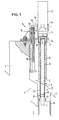
- Figure 1 is a simplified cut view of a first embodiment of the lighting device according to the invention, the light diffusor being retracted from the environment to be inspected.
- Figure 2 is a view similar to figure 1, the light diffusor penetrating into the environment.
- Figure 3 is a partial longitudinal cut view at an enlargened scale of the lighting device according to figure 1, with the light source and the glass rod being discoupled.
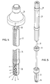
- Figure 4 is a perspective view of a second embodiment of the invention in which several glass rods are provided.
- Figure 5 is a perspective view of an alternative to the embodiment of figure 4.
- Referring to figures 1 and 2, the lighting device according to the invention comprises a
light source 1, e.g. a commercial metal vapour arc lamp of some hundred Watts associated with a reflector and avertical glasss rod 2, surrounded by ametal cladding tube 2a. The rod has at its free end a roughened surface which acts as a diffuser 3 for projecting light into theenvironment 7. The light source and the glass rod (light guide) are rigidly coupled through asleeve 4. The light source projects focussed light directly into the glass rod, the angle of the light cone being chosen such that a maximum amount of light is injected into the glass rod. The high efficiency of this coupling is also due to the high transparency of the used materials (sapphire glass window and high purity fused silica) and the narrow focussing point of the lamp light. - Two
windows light source 1 and theglass rod 2 and constitute a gastight separation between the atmosphere in theenvironment 7 to be illuminated and the ambient atmosphere. The windows are mounted in a twin-tubular connection member 13 which is locked to thesleeve 4 and tightly connected at its lower rim to thecladding tube 2a. Thelamp 1, therod 2 with itscladding tube 2a and itswindows connection member 13 and thecoupling sleeve 4 constitute as rigid but mobile unit which is received by and guided in an access tube 5 passing straight through theenclosure wall 6 and ending in theenvironment 7 to be illuminated. The lower portion of the mobile unit including the glass rod in its cladding tube is slidingly lodged in the access tube 5. Thecladding tube 2a of the glass rod abuts against ashoulder 2b of the rod and is provided with clampingfingers 2c gripping the glass rod below said shoulder. By releasing the fingers, it is possible to extract the glass rod from the cladding tube (and thus form the lighting system), especially for exchange or repair purposes. - The direction taken by the light emitted by the
lamp 1 in thelight guide 2 is visualized by the dotted lines 8 in figure 2. The light trapped in the guide is reflected internally at the wall of the glass rod and it leaves the rod through the diffusor 3. The entire surface of the rod end is roughened, so that the light is shed over 360°. - The displacement of the lighting device in the access tube 5, which is only longitudinal in both directions, is performed by the drive device 9. It comprises a
stationary structure 9a, bolted to the enclosure wall 6 (upper part), aspindle shaft 9b rotated by a motor (not shown) and anut 9c engaging the spindle and connected to abracket 9d of the drive device. The bracket is hinged to thesleeve 4. Thespindle shaft 9b is mounted in parallel to the axis of the lighting device. - In order to ensure the tightness of the
environment 7 between the access tube 5 and theglass rod 2, thewindows tubular connection member 13 by means ofbellows - The bellows are expanded when the lighting device is in its off-duty position (figure 2) and they are contracted when the device is in its operative position (figure 2). The length of the bellows in the expanded position, the penetration depth of the glass rod into the
environment 7 to be illuminated and the travelling path of thenut 9c on thespindle shaft 9b are adjusted to each other and determine the course of the lighting device. - The access tube 5 is laid through a
test channel 17 in theenclosure wall 6 and at its lower end, it is gastightly secured to thisenclosure wall 6. As the diameter of the access tube is smaller than that of the test channel, anadapter sleeve 18 is provided for bridging the gap. The sleeve is connected with one end to thetest channel 17 and with the other end to a shortadditional bellow 19, which in turn is connected to the access tube 5 in a gastight manner. This bellow is only provided for taking over slight movements of the access tube due for instance to thermal expansions or to manufacturing tolerances. The free space within the adapter sleeve can be used for mounting a flap valve (not shown) actuated by a weight for closing the opening of the access tube when the diffusor 3 is entirely retracted. - In figure 3, where the
coupling area 16 is more clearly shown, two (out of four)recesses 20 in thehousing 21 of the light source can be seen, which cooperate withsnap fingers 4a attached to thecoupling sleeve 4. Further, anannular groove 22 is provided on the outside of theconnection member 13 and cooperates withpegs 4b supported by the coupling sleeve. In the coupled position, thepegs 4b are engaged in theannular groove 22 and thesnap fingers 4a are engaged in therecesses 20. Discoupling of the snap fingers can be performed manually or by a matched tool, for example a sliding sleeve (not shown) movably put over thehousing 21 in such a way that, when the sleeve is moved downward or upward, it pushes theelastic fingers 4a into the recesses or makes them come out. Thus, thelamp 1 can be made easily accessible and its housing can be retracted without affecting theglass rod 2 or theenvironment 7 to be illuminated. - As results from the above description, all parts of the lighting device which may cause trouble have been placed outside the
environment 7; they are even disposed outside theenclosure wall 6. Maintenance, replacement and repair can thus be carried out without hindering the operations which are possibly being performed within theenvironment 7. - The diffusor according to figures 1 and 2 emits light over 360°. If spotlight is desired, only a part of the end portion of the glass rod is roughened, i.e. according to the desired direction of the light beam. In principle, also a rotation of the spotlight would be possible by rotating, for instance, the glass rod assembly. This, however, would imply that this assembly must be conceived in such a way that it can not only slide longitudinally, but can also rotate about its axis. This would complicate the guidance of the assembly in the access tube and increase the danger of movement hazards.
- Another solution of the problem to change the direction of a light beam is given by the embodiment of figure 4, showing only the lamp and the glass rod. In this case, the sole glass rod according to figure 1 is replaced by a
bundle 23 ofpartial rods 24, which receive individually light from the light source. - The bundle is composed of six partial rods each having its
own diffusion window 25. Thelight source 26 projects itslight cone 27 excentrically on the desired partial rod and the light can be injected into each selected partial rod either by rotatively moving the light source along a circular path, or by tilting the lamp in an inclined position around a tilt point located in the axis of the bundle, or by applying an asymmetrical optical deviator. - Figure 4 shows the general principle of such a composite light guide. One practical realisation thereof will now be described in accordance with figure 5. The
rods 29 have prismatic cross-section together forming a "daisy" design.Rings 30 keep the rods in position with respect to the main axis and to the outer cladding (not shown). Therings 30 are supported by a metal skeleton comprising ashaft 31,ribs 32 andradial spacers 33 fastened to the rings. Acap 34 secures the rods against axial displacement. - The described lighting device is radiation-resistant up to 10 exp-8 rad, high temperature resistant up to 450°C, and it is vacuum proof.
- If the glass rod were darkened after prolongated radiation emerging from the
environment 7, the light passing through the rod would heat up the rod by energy absorption, which heat would in turn make disappear the darkening, so that finally no decrease of the efficiency of the lighting device would occur. - The invention is not restricted to the preferred embodiments described above. The lighting device may also, if necessary, be mounted in a horizontal or an inclined position. Instead of two windows and two bellows, only one window and one bellow may be provided.
Claims (5)
Applications Claiming Priority (2)
| Application Number | Priority Date | Filing Date | Title |
|---|---|---|---|
| LU87151 | 1988-03-04 | ||
| LU87151A LU87151A1 (en) | 1988-03-04 | 1988-03-04 | LIGHTING DEVICE FOR CLOSED ROOMS |
Publications (2)
| Publication Number | Publication Date |
|---|---|
| EP0331064A1 true EP0331064A1 (en) | 1989-09-06 |
| EP0331064B1 EP0331064B1 (en) | 1993-08-04 |
Family
ID=19731030
Family Applications (1)
| Application Number | Title | Priority Date | Filing Date |
|---|---|---|---|
| EP19890103373 Expired - Lifetime EP0331064B1 (en) | 1988-03-04 | 1989-02-27 | A ligthing device for illuminating closed environments |
Country Status (7)
| Country | Link |
|---|---|
| EP (1) | EP0331064B1 (en) |
| DE (1) | DE68907950T2 (en) |
| DK (1) | DK169007B1 (en) |
| ES (1) | ES2042824T3 (en) |
| IE (1) | IE62209B1 (en) |
| LU (1) | LU87151A1 (en) |
| PT (1) | PT89898B (en) |
Cited By (8)
| Publication number | Priority date | Publication date | Assignee | Title |
|---|---|---|---|---|
| EP0446692A1 (en) * | 1990-03-15 | 1991-09-18 | Eta Ingenieurgesellschaft Für Energietechnik Und Energieanwendung Mbh | Lighting device using lightguides, especially for cold rooms and explosion-proof rooms |
| EP0657685A1 (en) * | 1993-11-12 | 1995-06-14 | General Electric Company | Easy to replace high brightness light source for use with light distribution system |
| WO1998049489A1 (en) * | 1997-04-26 | 1998-11-05 | British Nuclear Fuels Plc | Light assembly |
| WO1998051979A1 (en) * | 1997-05-15 | 1998-11-19 | Celsiustech Electronics Ab | Lighting device and method for mounting the lighting device |
| GB2356921A (en) * | 1999-12-02 | 2001-06-06 | John Clayton Ruddick | A lamp with a fibre optic cable to provide a light output externally of the lamp housing |
| WO2001073341A1 (en) * | 2000-03-25 | 2001-10-04 | Tissuemed Limited | Light source positioning device |
| WO2012126926A1 (en) * | 2011-03-23 | 2012-09-27 | Areva Nc | Sealed installation for handling material in powder form |
| EP3744428A1 (en) * | 2019-05-31 | 2020-12-02 | WEISS UMWELTTECHNIK GmbH | Lighting module and test chamber |
Families Citing this family (1)
| Publication number | Priority date | Publication date | Assignee | Title |
|---|---|---|---|---|
| CN111308730A (en) * | 2018-12-11 | 2020-06-19 | 核工业西南物理研究院 | Electric control movable diaphragm for pollution protection of glass window of fusion device |
Citations (3)
| Publication number | Priority date | Publication date | Assignee | Title |
|---|---|---|---|---|
| US1351562A (en) * | 1919-09-10 | 1920-08-31 | J B Wadman | Illusion apparatus |
| GB1109078A (en) * | 1966-02-23 | 1968-04-10 | Commissariat Energie Atomique | A support system for a lamp for lighting the inside of a hermetic enclosure |
| US3813514A (en) * | 1972-10-16 | 1974-05-28 | J Canty | Light piping unit for supplying radiant energy to the interior of a pressure vessel |
-
1988
- 1988-03-04 LU LU87151A patent/LU87151A1/en unknown
-
1989
- 1989-02-09 DK DK59789A patent/DK169007B1/en not_active IP Right Cessation
- 1989-02-27 EP EP19890103373 patent/EP0331064B1/en not_active Expired - Lifetime
- 1989-02-27 ES ES89103373T patent/ES2042824T3/en not_active Expired - Lifetime
- 1989-02-27 DE DE1989607950 patent/DE68907950T2/en not_active Expired - Fee Related
- 1989-02-27 IE IE61989A patent/IE62209B1/en not_active IP Right Cessation
- 1989-03-03 PT PT8989889A patent/PT89898B/en not_active IP Right Cessation
Patent Citations (3)
| Publication number | Priority date | Publication date | Assignee | Title |
|---|---|---|---|---|
| US1351562A (en) * | 1919-09-10 | 1920-08-31 | J B Wadman | Illusion apparatus |
| GB1109078A (en) * | 1966-02-23 | 1968-04-10 | Commissariat Energie Atomique | A support system for a lamp for lighting the inside of a hermetic enclosure |
| US3813514A (en) * | 1972-10-16 | 1974-05-28 | J Canty | Light piping unit for supplying radiant energy to the interior of a pressure vessel |
Cited By (11)
| Publication number | Priority date | Publication date | Assignee | Title |
|---|---|---|---|---|
| EP0446692A1 (en) * | 1990-03-15 | 1991-09-18 | Eta Ingenieurgesellschaft Für Energietechnik Und Energieanwendung Mbh | Lighting device using lightguides, especially for cold rooms and explosion-proof rooms |
| EP0657685A1 (en) * | 1993-11-12 | 1995-06-14 | General Electric Company | Easy to replace high brightness light source for use with light distribution system |
| WO1998049489A1 (en) * | 1997-04-26 | 1998-11-05 | British Nuclear Fuels Plc | Light assembly |
| US6179435B1 (en) | 1997-04-26 | 2001-01-30 | British Nuclear Fuels Plc | Light assembly |
| WO1998051979A1 (en) * | 1997-05-15 | 1998-11-19 | Celsiustech Electronics Ab | Lighting device and method for mounting the lighting device |
| GB2356921A (en) * | 1999-12-02 | 2001-06-06 | John Clayton Ruddick | A lamp with a fibre optic cable to provide a light output externally of the lamp housing |
| WO2001073341A1 (en) * | 2000-03-25 | 2001-10-04 | Tissuemed Limited | Light source positioning device |
| WO2012126926A1 (en) * | 2011-03-23 | 2012-09-27 | Areva Nc | Sealed installation for handling material in powder form |
| FR2973152A1 (en) * | 2011-03-23 | 2012-09-28 | Areva Nc | SEALED INSTALLATION FOR THE HANDLING OF POWDERED MATERIAL |
| EP3744428A1 (en) * | 2019-05-31 | 2020-12-02 | WEISS UMWELTTECHNIK GmbH | Lighting module and test chamber |
| US11506722B2 (en) | 2019-05-31 | 2022-11-22 | Weiss Technik Gmbh | Illumination device and test chamber |
Also Published As
| Publication number | Publication date |
|---|---|
| DK169007B1 (en) | 1994-07-25 |
| DE68907950D1 (en) | 1993-09-09 |
| EP0331064B1 (en) | 1993-08-04 |
| DK59789D0 (en) | 1989-02-09 |
| PT89898B (en) | 1994-03-31 |
| PT89898A (en) | 1989-11-10 |
| IE890619L (en) | 1989-09-04 |
| LU87151A1 (en) | 1989-10-26 |
| DE68907950T2 (en) | 1993-11-18 |
| IE62209B1 (en) | 1995-01-11 |
| ES2042824T3 (en) | 1993-12-16 |
| DK59789A (en) | 1989-09-05 |
Similar Documents
| Publication | Publication Date | Title |
|---|---|---|
| EP0331064B1 (en) | A ligthing device for illuminating closed environments | |
| KR0158676B1 (en) | Method and apparatus for optically coupling an element analysis system and a laser to liquid metal in a melting vessel | |
| JP2799291B2 (en) | Furnace inspection equipment | |
| KR950003440B1 (en) | Reflector telescope | |
| JP2005515435A (en) | Diffractometer and diffraction analysis method | |
| KR890013493A (en) | Optical beam alignment system and method | |
| US5416319A (en) | Optical scanner with dual rotating wedge mirrors | |
| US4082607A (en) | Fuel subassembly leak test chamber for a nuclear reactor | |
| US5192846A (en) | Equipment for drilling and/or closing off by laser the seal weld hole of a fuel rod | |
| US3737372A (en) | Installation for surveying the displacement of a structure in a nuclear reactor | |
| US4825445A (en) | Flowing gas laser discharge tube structure | |
| US5367407A (en) | Apparatus for supporting an aiming and orienting appliance useful in reflector systems | |
| KR840002381B1 (en) | Transfer and positioning apparatus for the irradiation of targets | |
| JPH08510064A (en) | Equipment used with radiation shielding enclosures | |
| Olthof | Multicolour far infrared photometry of galactic H2 regions | |
| US3485548A (en) | Stereoscopic telescope for the remote viewing of objects placed in a sealed examination cave | |
| JP3335592B2 (en) | Lighting equipment for airtight devices | |
| US4912529A (en) | Apparatus and method to compensate for refraction of radiation | |
| Kamus et al. | Wide-range astronomical telescope | |
| GB2070998A (en) | Welding by laser beam | |
| CN208125598U (en) | A kind of revolving scanning formula pernicious gas laser detector | |
| KR20220061139A (en) | How to install multi-function sights and multi-function sights | |
| White | Welding by laser beam | |
| RU329U1 (en) | Signal light | |
| Geitzholz et al. | Review of laser mega joule target area: Design and processes |
Legal Events
| Date | Code | Title | Description |
|---|---|---|---|
| PUAI | Public reference made under article 153(3) epc to a published international application that has entered the european phase |
Free format text: ORIGINAL CODE: 0009012 |
|
| AK | Designated contracting states |
Kind code of ref document: A1 Designated state(s): BE DE ES FR GB GR IT LU NL |
|
| 17P | Request for examination filed |
Effective date: 19900305 |
|
| 17Q | First examination report despatched |
Effective date: 19921002 |
|
| GRAA | (expected) grant |
Free format text: ORIGINAL CODE: 0009210 |
|
| AK | Designated contracting states |
Kind code of ref document: B1 Designated state(s): BE DE ES FR GB GR IT LU NL |
|
| REF | Corresponds to: |
Ref document number: 68907950 Country of ref document: DE Date of ref document: 19930909 |
|
| ITF | It: translation for a ep patent filed |
Owner name: STUDIO TORTA SOCIETA' SEMPLICE |
|
| ET | Fr: translation filed | ||
| REG | Reference to a national code |
Ref country code: ES Ref legal event code: FG2A Ref document number: 2042824 Country of ref document: ES Kind code of ref document: T3 |
|
| REG | Reference to a national code |
Ref country code: GR Ref legal event code: FG4A Free format text: 3009289 |
|
| EPTA | Lu: last paid annual fee | ||
| PLBE | No opposition filed within time limit |
Free format text: ORIGINAL CODE: 0009261 |
|
| STAA | Information on the status of an ep patent application or granted ep patent |
Free format text: STATUS: NO OPPOSITION FILED WITHIN TIME LIMIT |
|
| 26N | No opposition filed | ||
| PGFP | Annual fee paid to national office [announced via postgrant information from national office to epo] |
Ref country code: LU Payment date: 19961201 Year of fee payment: 9 |
|
| PGFP | Annual fee paid to national office [announced via postgrant information from national office to epo] |
Ref country code: BE Payment date: 19961213 Year of fee payment: 9 |
|
| PGFP | Annual fee paid to national office [announced via postgrant information from national office to epo] |
Ref country code: GR Payment date: 19961220 Year of fee payment: 9 |
|
| PGFP | Annual fee paid to national office [announced via postgrant information from national office to epo] |
Ref country code: GB Payment date: 19970127 Year of fee payment: 9 |
|
| PGFP | Annual fee paid to national office [announced via postgrant information from national office to epo] |
Ref country code: FR Payment date: 19970204 Year of fee payment: 9 |
|
| PGFP | Annual fee paid to national office [announced via postgrant information from national office to epo] |
Ref country code: ES Payment date: 19970214 Year of fee payment: 9 |
|
| PGFP | Annual fee paid to national office [announced via postgrant information from national office to epo] |
Ref country code: NL Payment date: 19970228 Year of fee payment: 9 |
|
| PGFP | Annual fee paid to national office [announced via postgrant information from national office to epo] |
Ref country code: DE Payment date: 19970324 Year of fee payment: 9 |
|
| PG25 | Lapsed in a contracting state [announced via postgrant information from national office to epo] |
Ref country code: LU Free format text: LAPSE BECAUSE OF NON-PAYMENT OF DUE FEES Effective date: 19980227 Ref country code: GB Free format text: LAPSE BECAUSE OF NON-PAYMENT OF DUE FEES Effective date: 19980227 |
|
| PG25 | Lapsed in a contracting state [announced via postgrant information from national office to epo] |
Ref country code: GR Free format text: LAPSE BECAUSE OF NON-PAYMENT OF DUE FEES Effective date: 19980228 Ref country code: FR Free format text: THE PATENT HAS BEEN ANNULLED BY A DECISION OF A NATIONAL AUTHORITY Effective date: 19980228 Ref country code: ES Free format text: LAPSE BECAUSE OF NON-PAYMENT OF DUE FEES Effective date: 19980228 Ref country code: BE Free format text: LAPSE BECAUSE OF NON-PAYMENT OF DUE FEES Effective date: 19980228 |
|
| BERE | Be: lapsed |
Owner name: EUROPEAN ATOMIC ENERGY COMMUNITY EURATOM Effective date: 19980228 |
|
| PG25 | Lapsed in a contracting state [announced via postgrant information from national office to epo] |
Ref country code: NL Free format text: LAPSE BECAUSE OF NON-PAYMENT OF DUE FEES Effective date: 19980901 |
|
| GBPC | Gb: european patent ceased through non-payment of renewal fee |
Effective date: 19980227 |
|
| NLV4 | Nl: lapsed or anulled due to non-payment of the annual fee |
Effective date: 19980901 |
|
| PG25 | Lapsed in a contracting state [announced via postgrant information from national office to epo] |
Ref country code: DE Free format text: LAPSE BECAUSE OF NON-PAYMENT OF DUE FEES Effective date: 19981103 |
|
| REG | Reference to a national code |
Ref country code: FR Ref legal event code: ST |
|
| REG | Reference to a national code |
Ref country code: ES Ref legal event code: FD2A Effective date: 20000403 |
|
| PG25 | Lapsed in a contracting state [announced via postgrant information from national office to epo] |
Ref country code: IT Free format text: LAPSE BECAUSE OF NON-PAYMENT OF DUE FEES;WARNING: LAPSES OF ITALIAN PATENTS WITH EFFECTIVE DATE BEFORE 2007 MAY HAVE OCCURRED AT ANY TIME BEFORE 2007. THE CORRECT EFFECTIVE DATE MAY BE DIFFERENT FROM THE ONE RECORDED. Effective date: 20050227 |