EP0329402B1 - Systems and markers using magnetic or spin resonance phenomena - Google Patents
Systems and markers using magnetic or spin resonance phenomena Download PDFInfo
- Publication number
- EP0329402B1 EP0329402B1 EP89301425A EP89301425A EP0329402B1 EP 0329402 B1 EP0329402 B1 EP 0329402B1 EP 89301425 A EP89301425 A EP 89301425A EP 89301425 A EP89301425 A EP 89301425A EP 0329402 B1 EP0329402 B1 EP 0329402B1
- Authority
- EP
- European Patent Office
- Prior art keywords
- marker
- magnetic
- resonance
- resonant
- resonant material
- Prior art date
- Legal status (The legal status is an assumption and is not a legal conclusion. Google has not performed a legal analysis and makes no representation as to the accuracy of the status listed.)
- Expired - Lifetime
Links
Images


Classifications
-
- G—PHYSICS
- G01—MEASURING; TESTING
- G01R—MEASURING ELECTRIC VARIABLES; MEASURING MAGNETIC VARIABLES
- G01R33/00—Arrangements or instruments for measuring magnetic variables
- G01R33/20—Arrangements or instruments for measuring magnetic variables involving magnetic resonance
- G01R33/44—Arrangements or instruments for measuring magnetic variables involving magnetic resonance using nuclear magnetic resonance [NMR]
- G01R33/441—Nuclear Quadrupole Resonance [NQR] Spectroscopy and Imaging
-
- G—PHYSICS
- G01—MEASURING; TESTING
- G01R—MEASURING ELECTRIC VARIABLES; MEASURING MAGNETIC VARIABLES
- G01R33/00—Arrangements or instruments for measuring magnetic variables
- G01R33/20—Arrangements or instruments for measuring magnetic variables involving magnetic resonance
- G01R33/28—Details of apparatus provided for in groups G01R33/44 - G01R33/64
- G01R33/281—Means for the use of in vitro contrast agents
-
- G—PHYSICS
- G01—MEASURING; TESTING
- G01R—MEASURING ELECTRIC VARIABLES; MEASURING MAGNETIC VARIABLES
- G01R33/00—Arrangements or instruments for measuring magnetic variables
- G01R33/20—Arrangements or instruments for measuring magnetic variables involving magnetic resonance
- G01R33/44—Arrangements or instruments for measuring magnetic variables involving magnetic resonance using nuclear magnetic resonance [NMR]
- G01R33/48—NMR imaging systems
- G01R33/58—Calibration of imaging systems, e.g. using test probes, Phantoms; Calibration objects or fiducial markers such as active or passive RF coils surrounding an MR active material
-
- G—PHYSICS
- G01—MEASURING; TESTING
- G01V—GEOPHYSICS; GRAVITATIONAL MEASUREMENTS; DETECTING MASSES OR OBJECTS; TAGS
- G01V3/00—Electric or magnetic prospecting or detecting; Measuring magnetic field characteristics of the earth, e.g. declination, deviation
- G01V3/14—Electric or magnetic prospecting or detecting; Measuring magnetic field characteristics of the earth, e.g. declination, deviation operating with electron or nuclear magnetic resonance
Definitions
- This invention relates to systems and markers using magnetic or spin resonance phenomena for practical purposes. More particularly, but not exclusively, it is concerned with the use of magnetic resonance, spin resonance and spin-echo phenomena in systems for the surveillance, recognition, detection, sorting or monitoring of articles, stock or personnel.
- the applications of such systems include electronic article surveillance (theft prevention) and personnel verification.
- the magnetic resonance phenomena are associated with nuclear, electron, atomic or molecular magnetic dipole moments acting individually or cooperatively in the presence of magnetic fields to give nuclear magnetic resonance (NMR), nuclear quadrupole resonance (NQR), electron spin resonance or electron paramagnetic resonance (ESR, EPR), ferromagnetic resonance, ferrimagnetic resonance, antiferromagnetic resonance, domain wall resonance, spin-wave resonance or spin-echoes.
- NMR nuclear magnetic resonance
- NQR nuclear quadrupole resonance
- ESR electron paramagnetic resonance
- ferromagnetic resonance ferrimagnetic resonance
- antiferromagnetic resonance domain wall resonance
- spin-wave resonance or spin-echoes ferromagnetic resonance
- the magnetic resonance is exhibited when the dipole moments precessing in the magnetic fields absorb and re-radiate microwave or radio frequency electromagnetic radiation at or very close to the precession frequency.
- EP 0 228 692 discloses a skin marker for use in medical diagnosis by means of both X-ray tomography and nuclear magnetic resonance imaging.
- This skin marker is used for steric correlation of an X-ray image of a part of a patient's body with an NMR image of the same region of the patient's body. It is necessary for the marker to be free of ferromagnetic materials, as these interfere with the NMR imaging. Furthermore, there is no suggestion of selecting the magnetic characteristics of such a marker so as to generate an individually identifiable frequency response and thereby to distinguish between and identify different markers.
- a variety of electronic article surveillance or personnel detection systems currently exist. They involve detection of macroscopic magnetic properties or macroscopic resonances associated with LC electrical circuit resonances, or with bulk mechanical vibrational resonances, or with non-linear electrical transponders or with high-permeability magnetically saturating soft magnetic elements.
- EP 0 096 182 An example of a detection system employing magnetostrictive resonance is disclosed in EP 0 096 182.
- This type of system employs a marker for article surveillance comprising elongated strips of a magnetostrictive material arranged to undergo macroscopic physical resonance at a frequency of around 15 kHz when subjected to an oscillating magnetic field in a detection zone.
- a ferromagnetic element disposed adjacent to each of the strips of magnetostrictive material is adapted, upon being magnetized, to magnetically bias the strips and thereby arm them to resonate at their preselected frequencies.
- EP-A-0 215 605 discloses a detection system which includes a marker containing an inductive-capacitive resonant circuit.
- the marker is made reversibly deactivatable and reactivatable by the addition of a piece of magnetic material that forms a magnetic circuit enclosing the inductive component, and by means, such as a piece of permanently magnetizable material, for controllably magnetically biasing the magnetic material.
- the detection system further includes an interrogation zone in an exit-way comprising antennas for generating and receiving radio frequency signals. Upon passage within the zone of an object to which is affixed a marker, the marker, when in its sensitized state, will be excited to produce oscillations at its resonance frequency.
- Materials exhibiting the atomic resonance phenomena described above can be used in accordance with this invention for article recognition and/or detection and for security surveillance. Such use is possible because they can have extremely sharply defined resonant frequencies, which may be used to indicate their presence or identity. This can be achieved in a preferred embodiment of the invention by the use of a microwave or radio frequency emitting interrogation system which also detects an increase in the absorption of the interrogating electromagnetic energy or re-emission of electromagnetic energy by the marker at the resonant frequency.
- a method of electronic article or personnel surveillance which comprises monitoring, recognising or detecting the location of an article, or sorting or selecting an article from a plurality of articles, or personnel identification, wherein said article or personnel is tagged with a marker comprising a material which supports a predetermined resonance property which serves to identify said article or personnel, which method is characterised in that said resonance is magnetic resonance and in that the method comprises the steps of:
- a marker for use in the method of the invention will be provided with means whereby the marker can be attached to an article or body (e.g. a person) the location of which is to be monitored, recognised or detected or which is to be sorted or selected from a plurality of articles or bodies.
- an article or body e.g. a person
- a marker for use in the method of the first aspect which marker comprises a substrate which supports internally or externally a plurality of magnetically active regions, of which at least one region comprises a material selected to support a predetermined magnetic resonance property, and of which at least one other region comprises a permanent or semi-permanent magnet, wherein said material is electrically non-conductive and said magnetic resonance is electron spin resonance (ESR).
- ESR electron spin resonance
- a marker for use in the method of the first aspect which marker comprises a substrate which supports internally or externally a plurality of magnetically active regions, of which at least one region comprises a material selected to support a predetermined magnetic resonance property, and of which at least one other region comprises a permanent or semi-permanent magnet, wherein said material is electrically non-conductive and said magnetic resonance is nuclear magnetic resonance (NMR).
- NMR nuclear magnetic resonance
- a marker in the method of the first aspect, which marker comprises a substrate which supports internally or externally a plurality of magnetically active regions, of which at least one region comprises a material selected to support a predetermined magnetic resonance property, and of which at least one other region comprises a permanent or semi-permanent magnet, wherein said material is electrically non-conductive.
- the preferred magnetic resonance phenomena for the purposes of the present invention are ESR and spin echoes.
- the invention will be described hereinafter with particular reference to these phenomena, although it is to be understood that the invention is not restricted to systems or articles which make use only of these phenomena.
- the modifications necessary to practise the invention using other magnetic resonance phenomena, e.g. NMR or ferrimagnetic resonance, will be apparent to those skilled in the art.
- the magnetic field required to produce defined resonances can be supplied either as a large field over the entire interrogation volume, or by a small permanent or semi-permanent magnet placed close to the resonant material and carried round with it and the article.
- a permanent or semi-permanent magnet and the resonant material are fabricated as a unit which constitutes the detectable marker.
- This can be a d.c. field to counteract, for example, the Earth's field.
- a small a.c. field operating at a low frequency, typically of a few kHz can be used to scan repeatedly across resonance at this identifiable second frequency.
- Markers in accordance with the present invention are distinct and identifiable (and different markers may be fabricated so as to have a unique magnetic resonance signature) since the combination of the resonating material and an established magnetic field is sufficiently unique to give a resonance which will not occur with everyday objects (or with other markers in accordance with this invention).
- the resonant material may be a solid, or a solid solution, or a solid/liquid solution, or a liquid/liquid solution.
- a detection system including a marker as defined above, which system comprises a gate which, in use, will be located at a point of sale location or between a point of sale location and an exit from the premises containing said point of sale location, wherein said gate comprises means for emitting radiation in the microwave or radiofrequency waveband; and means for detecting radiation emitted by the marker in response to a magnetic field in conjunction with said microwave or radiofrequency radiation.
- a detection system in the method of the first aspect, including the use of a marker as defined above, which system comprises a gate which, in use, will be located at a point of sale location or between a point of sale location and an exit from the premises containing said point of sale location, wherein said gate comprises means for emitting radiation in the microwave or radiofrequency waveband; and means for detecting radiation emitted by the marker in response to a magnetic field in conjunction with said microwave or radiofrequency radiation.
- the microwave radiation is preferably pulsed so that absorption by the marker is time-differentiated from emission of radiation from the active atoms within the marker due to decay of the excited ESR or NMR state. Detection of emitted radiation thus indicates presence of a marker which has not been removed by an assistant at the point of sale.
- Examples of materials which can be used for ESR detection include paramagnetic salts - i.e. salts containing paramagnetic ions, for example Cu2+, Mn2+, Fe3+, Gd3+, Cr3+, Tb3+, Er3+ - in particular transition group metal ions of the iron group, the palladium group, the platinum group, and the actinide group.
- certain organic molecules or stable free radicals have an unpaired electron and are paramagnetic - examples are naphthalene, nitroxides, diphenyl picryl hydrazyl, and triphenyl methyl. Crystalline solids containing ionic impurities are also suitable, as well as certain naturally occuring minerals exemplified by ultramarine.
- the active paramagnetic moieties in the magnetically resonant material are preferably spaced apart from one another on the atomic scale in order to minimise coupling between neighbouring paramagnetic ions and hence give a more sharply defined resonance.
- salts containing paramagnetic metal ions are advantageously used in dilute form, for example dispersed to 1% dilution (by weight) in a diamagnetic salt or medium, for example in magnesium oxide.
- nuclei with a net nuclear spin such as hydrogen, carbon, nitrogen, chlorine, phosphorus, magnesium and calcium
- NMR detection can all be used for NMR detection. Isotopes with low natural abundance will give improved discrimination against false alarms.
- the magnetic material is advantageously a crystalline metal, an amorphous metal, or a crystalline or powdered ferrite-type material such as that used in magnetic recording media.
- the magnet may be a permanent magnet - i.e. have very high coercivity; or a semi-permanent, switchable magnet - preferably one with coercivity between 100Am ⁇ 1 and 50,000Am ⁇ 1.
- the magnetic material may also be a composite of materials of differing properties designed to produce a high intensity, uniform field.
- the marker may comprise a magnet in the form of a sheet of material placed over or underneath the resonant material or, preferably, the resonant material and the magnet may be substantially co-planar.
- the resonant material is adjacent to the tips or edges of a strip or sheet of the magnetic material, or placed in a small gap in an annulus or toroid of the magnetic material.
- a magnetic material is intimately mixed with the resonant material to form a magnetic matrix around it, or the magnetic material is used to encapsulate the resonant material.
- marker there is a plurality of magnetically active regions arranged physically so as to generate a unique magnetic resonance signal when the marker is interrogated with a predetermined magnetic field.
- the marker in such a way that the magnetic field from the magnetic material is of high amplitude and very uniform across the sample of the resonant material. This keeps the resonant signal sharp - i.e. narrow and of maximum amplitude. Further embodiments with this advantageous property will be obvious to those skilled in the design of magnetic systems.
- the resonance frequency shown by the resonant material depends, amongst other parameters, on the strength of the magnetic field in which it is placed. If a magnetic field of non-uniform spatial distribution is applied to the material, then different regions of the material will have different resonance frequencies. In another embodiment of this invention this spread of frequencies is used to compensate for any manufacturing variations in the marker of this invention, or in a detection system for identifying such a marker; the same effect can also compensate for any unknown or unpredictable external magnetic field (for example the Earth's field) which might affect the magnetic field which is deliberately applied by the detection system to generate a specific resonance in the marker.
- any unknown or unpredictable external magnetic field for example the Earth's field
- the magnetic element in the marker or the detection system may be arranged to generate a diverging magnetic field in order to increase the number of different orientations at which magnetic field lines intersect the marker.
- the marker carrying a plurality of magnetically active regions (which may, for example, comprise soft magnetic regions, semi-hard magnetic regions and hard magnetic regions as well as the magnetically resonant material) is used in conjunction with a suitable detection system, whereby the magnetic field generated within the marker by the field applied by the detection system is inhomogeneous and has a specific and characteristic form.
- a suitable detection system whereby the magnetic field generated within the marker by the field applied by the detection system is inhomogeneous and has a specific and characteristic form.
- This result may be achieved by using, in the marker, portions of resonant material positioned so that when subjected to the applied field of the detection system, they are located at points or regions having a different field gradient.
- the same result may also be achieved with a marker including several small ferromagnetic elements between a major magnetically active region (e.g.
- the range and frequencies of the resonant responses from the marker can be used as information representing a code which is a further distinguishing feature of the identity of the resonant element or of the article or body carrying the marker.
- This coding may be altered by positioning samples of the resonant material at various distances from a magnetic element or plurality of elements of fixed magnetisation. If a plurality of resonant elements is used to generate a plurality of distinguishable resonances, then various combinations of position and hence of resonances will represent different identifier codes.
- the positions of the resonant elements are fixed, but they are placed close to a plurality of magnetically switchable semi-permanent magnetic elements so that the magnetic environment of the resonant elements can be altered in a non-contact fashion by changes in an external, applied magnetic field.
- the identifier codes may be altered by this method in a controlled manner.
- Magnetic resonant materials can also exhibit echo phenomena such as spin echoes or ferromagnetic echoes under certain conditions.
- One class of these echo phenomema rely on non-linear coupling mechanisms between energy storage modes in the materials, and the amplitude of the echo is sensitive to a number of parameters such as strain in the material, the shape of the sample, the homogeneity of the magnetic field in the sample, and the time delay for excitation of the echo.
- the echo is manifested as a microwave echo emitted by the sample in response to a microwave pulse or train of pulses incident on the material, usually following a specific time after the final incident pulse.
- the spin echo relies upon magnetoelastic (or magnetostrictive) coupling of energy to mechanical vibrations of the detectable marker, and the spin-echo delay time can be made to depend upon the dimensions of the marker.
- the echo delay time may depend upon the shape of a sample or crystal of the material, with a randomly-shaped crystal showing a number of echo delays or echo resonances with a variety of amplitudes. These can be used to distinguish an individual crystal of the material. It is a characteristic of one class of spin echo that the echo is enhanced by irregular shape of the crystal and by an inhomogenous magnetic field. This type of echo is particularly suited to implementation in manufactured detectable markers, where inhomogeneity and irregularity are likely to occur.
- a unique identifier code can be generated. This can be used to identify an individual person or article which carries the crystal in a security system.
- An example of the production of a crystal of unique shape is to shatter a very small crystal, and then use individual random shards. The shards can be interrogated remotely by microwaves, and very small volumes can be detected under resonant echo excitation.
- the spin echoes are excited by two shorter bursts of electromagnetic energy at the resonant frequency separated by a time t1.
- a third, echo response results at the same time interval t1 after the second burst as a result of the evolution of the magnetisation resulting from constructive interference of precessing magnetic spins induced by the two interrogation pulses in the spin system.
- the time t1 is carefully chosen with reference to the spin relaxation times of the magnetically resonant moiety in order to maximise the amplitude of the echo which indicates the presence of the marker material.
- the excitation pulse duration t p is short compared to one cycle time t r of the resonant frequency, and furthermore if both t p and t1 are much shorter than the spin relaxation or decay times for the aligned spin system. Maximal spin echo amplitude is observed if t p /t r is approximately 1/3.
- the echo delay time may be several microseconds, with the shape and amplitude of the echo as a function of time dependent on the input signal shape. Both of these characteristics may be used as identifiers of the presence of the spin-echo material.
- Phenomena which can be used for this application include ferromagnetic echoes, ferrimagnetic echoes, spin wave echoes and antiferromagnetic echoes.
- the materials which exhibit these phenomena may be crystalline, amorphous, multiphase or composite manufactured materials. Particular examples of materials which show these echo phenomena are yttrium iron garnet and yttrium aluminium garnet.
- the extreme sharpness of the resonance exhibited by certain substances exhibiting magnetic resonances can be exploited to advantage in two embodiments of the invention.
- the narrow resonance indicates a low damping or loss in the oscillating spin systems, which may also be expressed as a high oscillatory quality factor, or Q-factor. This in turn may be viewed as a high effective gain, leading to an anomalously high absorption of energy from the interrogating electromagnetic field at or near to resonance.
- This sharp resonant absorption is highly characteristic of the marker material. In one embodiment of the invention, this absorption, from a continuously applied interrogating field, is detected to indicate the presence of the marker.
- the high Q-factor is also manifested as a prolonged emission of electromagnetic energy from the marker at a characteristic frequency (the resonant frequency) or frequencies after the interrogating elctromagnetic field has been switched off.
- the interrogation field is pulsed on for short periods of time and then switched off.
- the characteristic emission from the marker continues after the excitation has been stopped, and is detected a few microseconds or even milliseconds later.
- Particular uniqueness associated with the marker can also be derived from measuring the phase of this emission and/or the specific way in which the amplitude and phase evolves in time. This latter embodiment is particularly useful where the dynamic range in the detection system limits the ability to detect small amounts of absorption from a continuously applied interrogation field.
- a seventh aspect of this invention there is provided a method of electronic article or personnel surveillance as defined above, further characterised in that said marker may be deactivated by a predetermined alteration of the magnetic resonance properties of said magnetically resonant material.
- the means for deactivating the resonant material may be a deactivation zone provided on or in the marker itself; or it may be an element which responds directly or indirectly to an externally applied force so as to alter the chemical, crystallographic, or physical nature of the detectable marker.
- the resonance frequency is altered by inducing a chemical or crystallographic change in the resonant material. These changes alter the local atomic environments of the magnetic dipoles and hence their effective magnetic moments.
- the change in resonance frequency leads either to the marker not being detected in the expected bandwidth of the detection system, or to the altered frequency being recognized as characteristic of disarmed markers.
- Chemical or physical changes can also be used in a similar fashion to lower the quality factor of the resonant species, i.e. to destroy the resonance, sufficiently for the marker to be no longer detectable, and hence to deactivate it. Suitable techniques to induce these changes are heating by an electromagnetic or particle beam, or by friction, cooling, release of a reactive chemical agent onto the resonant material, dissolving in a solvent, or physically breaking up the material.
- the deactivation is carried out by changes to the magnetic field of the magnetic element. This is achieved by a degaussing magnetic field, by heating or mechanical working or a combination of the two, by physically breaking up the configuration of the magnetic material, or by changing the direction or amplitude of the magnetisation in the magnetic element in the region of the resonant material by applying an external field to the element or to secondary elements close to the main element. Even small changes in the magnetic field at the resonant material will lead to detectable changes in the resonant frequency, and hence to an indication of deactivation.
- a resonant material 1 and a magnetising material 2 are substantially planar.
- the detectable marker may have a variety of configurations.
- material 1 is contained in the gap in an annulus of material 2, the magnetic material preferentially being magnetised circumferentially to generate a high magnetic field across the gap.
- Figure 1b small samples of the resonant material 1 are placed at the tips of a sheet or strip of the magnetic material 2, which is preferentially magnetised longitudinally to produce a high magnetic field across the resonant material.
- these configurations may equally well be implemented as substantially 3-dimensional structures - i.e. as toroids or rods or blocks. However, laminar structures are preferred since they are more easily incorporated into inobtrusive markers.
- the resonant material 1 is incorporated, mixed, or encapsulated with the magnetic material 2 in order to improve the magnetic field coupling to material 1.
- the magnetic field 3 generated by the magnetic material 2 is shown schematically to be diverging over the region of the resonant material 1. This may be exploited in the manner described hereinbefore to give a variety of resonant conditions within a single sample of material 1, both as regards orientation of the magnetic moments with respect to the detection apparatus, and as regards the exact value of the resonant frequency.
- Figure 4 shows how diverging fields of the type shown in Figure 3 may be further exploited by placing a plurality of elements 1 of resonant material in positions which are either magnetically equivalent or magnetically different around the magnetising material 2. It will be clear that the plurality of elements 1 may also be implemented as a single extended element. With careful positioning of a plurality of elements, a number of relatively discrete resonance conditions may be established. This multiplicity of different resonances may be used as described hereinbefore to generate a unique identifier code attributable to a single article, person, or group of articles or people.
- Figure 5 shows the time evolution of electromagnetic energy during generation of a spin-echo pulse.
- the height of the pulses represents the amplitude of the electromagnetic field, and the horizontal axis shows time.
- Pulse 1 and pulse 2 are applied by the pulsed external radiofrequency or microwave source at a time interval t1.
- the resonant material produces a discrete response pulse at a time t1 after the second pulse, and this response pulse is detected to indicate the presence of the detectable marker.
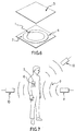
- Figure 6 shows how a detectable marker of the type shown in Figure 1 may be incorporated into an antipilferage tag or an identifying marker.
- the components 1 and 2 comprising the marker are placed onto a substrate 4, or manufactured by direct deposition on the substrate.
- the substrate 4 may be a sheet of paper or polymer or other flexible material, or a non-flexible sheet or block of supporting material.
- the underside of the substrate may be covered in a layer of glue or other fixing agent or mechanism to secure it to the object to be marked or protected.
- a face covering or face paper 5 may be laminated to the marker.
- Figure 7 shows a schematic of the identification or detection of the passage of a concealed marker 6 which is attached to some protected article 7.
- a microwave or radiofrequency source emits electromagnetic radiation 9.
- the absorption of energy due to the presence of the marker or the re-emission of energy by the marker is detected by one or more microwave or radiofrequency receivers 10.
- LPF represents a low-pass filter
- PSD represents a phase sensitive detector
- 'Amp' represents signal amplifier.
- the gates are electronic switches to rapidly switch the transmission or reception on or off, to enable the system to work in a pulsed mode.
- the switch timing is controlled by the timing generator, and may be implemented either by PIN diodes or by a combination of circulators and PIN switches to give extremely fast switching times (less than 0.2ns).
- the limiter is necessary to protect the first amplifier (preferably a low noise amplifier) from residual leakage of transmit signal through the receiver gate in its off condition.
- phase sensitive detectors in quadrature allows full measurement of the phase of the signal.
- the phase and amplitude characteristics of the signal are analysed by the computer or processing unit to assess if a marker is present.
- the electronic gates in the circuit are not necessary.
- the local oscillator may be swept frequency oscillator, producing an interrogation frequency which sweeps across the expected range of the marker resonance frequency.
- This Example describes the construction of an antipilferage marker comprising a magnetic material and a resonant material, assembled onto a substrate.
- the magnetic material is a semi-permanent magnet made from Vacozet, a proprietary material produced by Vacuumschmeltze of West Germany. This material has a high remanent magnetization and is manufactured with a variety of coercive forces. In the chosen embodiment, material with a coercive force of 3,000Am ⁇ 1 was used, although this choice is not critical - a coercive force of over 10,000Am ⁇ 1 can be used. Alternatively, other magnetic materials such as nickel or magnetic stainless steels may be used in this embodiment as the magnetic element.
- An annulus of thickness 40 ⁇ m, diameter 10mm, and track width 3mm is punched from a sheet of the material and stuck to a substrate of paper coated with a pressure-sensitive glue.
- Approximately 1mg of a powder in the form of an impermeable resin containing small crystals of diphenyl picryl hydrazyl of diameter approximately 100 ⁇ m is then placed centrally in the gap in the magnetic annulus, and the marker is then covered with a protective layer of paper.
- the composite is then cut to a square label of dimensions 12mm X 12mm.
- the resonant material experiences a magnetic field of approximately 30mT, and has an electron spin resonant frequency of approximately 1GHz with a resonance half width less than 1MHz, indicating a decay time after excitation of more than 1 microsecond.
- the magnetic material in this Example was chosen so that a degaussing field of maximum amplitude of the order of 10,000 A/m could be used to deactivate the marker (by altering the resonant properties of the resonant material).
- Example 2 is similar to Example 1 in that the magnetizing element is constructed in the same manner.
- the resonant material in this Example consists of small spheres, 100 ⁇ m in diameter, of yttrium iron garnet.
- the material shows a ferromagnetic resonance at 1GHz with a quality factor of approximately 5,000 giving a decay time, again, of more than 1 microsecond.
- the resonant material is the same as in Example 1 or Example 2, but the magnetic material is replaced by a permanent magnetic material.
- Alcomax is a suitable proprietary material, as is Ferroba, a barium ferrite. These materials are deposited in the form of a powder slurry mixed with a thermosetting resin, and printed in a layer approximately 100 ⁇ m thick. The material is magnetized by placing it close to a permanent magnet or by a pulsed current in a coil adjacent to or threading the annulus. Finally the slurry is set by gentle heating of the glue, to fix the direction of magnetization.
Abstract
Description
- This invention relates to systems and markers using magnetic or spin resonance phenomena for practical purposes. More particularly, but not exclusively, it is concerned with the use of magnetic resonance, spin resonance and spin-echo phenomena in systems for the surveillance, recognition, detection, sorting or monitoring of articles, stock or personnel. The applications of such systems include electronic article surveillance (theft prevention) and personnel verification.
- The magnetic resonance phenomena are associated with nuclear, electron, atomic or molecular magnetic dipole moments acting individually or cooperatively in the presence of magnetic fields to give nuclear magnetic resonance (NMR), nuclear quadrupole resonance (NQR), electron spin resonance or electron paramagnetic resonance (ESR, EPR), ferromagnetic resonance, ferrimagnetic resonance, antiferromagnetic resonance, domain wall resonance, spin-wave resonance or spin-echoes. For convenience, the term 'magnetic resonance' will be used herein to include all of these magnetic and spin phenomena. The magnetic resonance is exhibited when the dipole moments precessing in the magnetic fields absorb and re-radiate microwave or radio frequency electromagnetic radiation at or very close to the precession frequency.
- It is known from Electro Conference Record, 24th-26th April, 1979, vol. 4, J.R. Gonano: "Nuclear Magnetic Resonance and Nuclear Quadrupole Resonance for Bomb Detection" pp. 1-5 to use NMR and NQR techniques to detect explosives in suitcases. The suitcases are carried through a magnetic field on a conveyor belt, and subjected to NMR and/or NQR scans in order to determine the presence or absence of explosives in the suitcases.
- EP 0 228 692 discloses a skin marker for use in medical diagnosis by means of both X-ray tomography and nuclear magnetic resonance imaging. This skin marker is used for steric correlation of an X-ray image of a part of a patient's body with an NMR image of the same region of the patient's body. It is necessary for the marker to be free of ferromagnetic materials, as these interfere with the NMR imaging. Furthermore, there is no suggestion of selecting the magnetic characteristics of such a marker so as to generate an individually identifiable frequency response and thereby to distinguish between and identify different markers.
- A variety of electronic article surveillance or personnel detection systems currently exist. They involve detection of macroscopic magnetic properties or macroscopic resonances associated with LC electrical circuit resonances, or with bulk mechanical vibrational resonances, or with non-linear electrical transponders or with high-permeability magnetically saturating soft magnetic elements.
- An example of a detection system employing magnetostrictive resonance is disclosed in EP 0 096 182. This type of system employs a marker for article surveillance comprising elongated strips of a magnetostrictive material arranged to undergo macroscopic physical resonance at a frequency of around 15 kHz when subjected to an oscillating magnetic field in a detection zone. A ferromagnetic element disposed adjacent to each of the strips of magnetostrictive material is adapted, upon being magnetized, to magnetically bias the strips and thereby arm them to resonate at their preselected frequencies.
- EP-A-0 215 605 discloses a detection system which includes a marker containing an inductive-capacitive resonant circuit. The marker is made reversibly deactivatable and reactivatable by the addition of a piece of magnetic material that forms a magnetic circuit enclosing the inductive component, and by means, such as a piece of permanently magnetizable material, for controllably magnetically biasing the magnetic material. The detection system further includes an interrogation zone in an exit-way comprising antennas for generating and receiving radio frequency signals. Upon passage within the zone of an object to which is affixed a marker, the marker, when in its sensitized state, will be excited to produce oscillations at its resonance frequency.
- Materials exhibiting the atomic resonance phenomena described above can be used in accordance with this invention for article recognition and/or detection and for security surveillance. Such use is possible because they can have extremely sharply defined resonant frequencies, which may be used to indicate their presence or identity. This can be achieved in a preferred embodiment of the invention by the use of a microwave or radio frequency emitting interrogation system which also detects an increase in the absorption of the interrogating electromagnetic energy or re-emission of electromagnetic energy by the marker at the resonant frequency.
- According to one aspect of this invention, there is provided a method of electronic article or personnel surveillance which comprises monitoring, recognising or detecting the location of an article, or sorting or selecting an article from a plurality of articles, or personnel identification, wherein said article or personnel is tagged with a marker comprising a material which supports a predetermined resonance property which serves to identify said article or personnel, which method is characterised in that said resonance is magnetic resonance and in that the method comprises the steps of:
- i) subjecting said magnetically resonant material simultaneously to a static magnetic field and to electromagnetic radiation;
- ii) observing a magnetic resonance property by detecting the absorption or reemission of said electromagnetic radiation by said marker at characteristic magnetic resonance frequencies; and
- iii) correlating said observed magnetic resonance property with said predetermined magnetic resonance property in order to identify said article or personnel.
- Generally, a marker for use in the method of the invention will be provided with means whereby the marker can be attached to an article or body (e.g. a person) the location of which is to be monitored, recognised or detected or which is to be sorted or selected from a plurality of articles or bodies.
- According to a second aspect of the present invention, there is provided a marker for use in the method of the first aspect, which marker comprises a substrate which supports internally or externally a plurality of magnetically active regions, of which at least one region comprises a material selected to support a predetermined magnetic resonance property, and of which at least one other region comprises a permanent or semi-permanent magnet, wherein said material is electrically non-conductive and said magnetic resonance is electron spin resonance (ESR).
- According to a third aspect of the present invention, there is provided a marker for use in the method of the first aspect, which marker comprises a substrate which supports internally or externally a plurality of magnetically active regions, of which at least one region comprises a material selected to support a predetermined magnetic resonance property, and of which at least one other region comprises a permanent or semi-permanent magnet, wherein said material is electrically non-conductive and said magnetic resonance is nuclear magnetic resonance (NMR).
- According to a fourth aspect of the present invention, there is provided the use of a marker in the method of the first aspect, which marker comprises a substrate which supports internally or externally a plurality of magnetically active regions, of which at least one region comprises a material selected to support a predetermined magnetic resonance property, and of which at least one other region comprises a permanent or semi-permanent magnet, wherein said material is electrically non-conductive.
- The preferred magnetic resonance phenomena for the purposes of the present invention are ESR and spin echoes. The invention will be described hereinafter with particular reference to these phenomena, although it is to be understood that the invention is not restricted to systems or articles which make use only of these phenomena. The modifications necessary to practise the invention using other magnetic resonance phenomena, e.g. NMR or ferrimagnetic resonance, will be apparent to those skilled in the art.
- The magnetic field required to produce defined resonances can be supplied either as a large field over the entire interrogation volume, or by a small permanent or semi-permanent magnet placed close to the resonant material and carried round with it and the article. Thus in one embodiment a permanent or semi-permanent magnet and the resonant material are fabricated as a unit which constitutes the detectable marker. In this embodiment it may still be advantageous to impose a small externally-generated magnetic field. This can be a d.c. field to counteract, for example, the Earth's field. Alternatively a small a.c. field operating at a low frequency, typically of a few kHz, can be used to scan repeatedly across resonance at this identifiable second frequency.
- Markers in accordance with the present invention are distinct and identifiable (and different markers may be fabricated so as to have a unique magnetic resonance signature) since the combination of the resonating material and an established magnetic field is sufficiently unique to give a resonance which will not occur with everyday objects (or with other markers in accordance with this invention).
- The resonant material may be a solid, or a solid solution, or a solid/liquid solution, or a liquid/liquid solution.
- According to a fifth aspect of the present invention, there is provided a detection system including a marker as defined above, which system comprises a gate which, in use, will be located at a point of sale location or between a point of sale location and an exit from the premises containing said point of sale location, wherein said gate comprises means for emitting radiation in the microwave or radiofrequency waveband; and means for detecting radiation emitted by the marker in response to a magnetic field in conjunction with said microwave or radiofrequency radiation.
- According to a sixth aspect of the present invention, there is provided the use of a detection system in the method of the first aspect, including the use of a marker as defined above, which system comprises a gate which, in use, will be located at a point of sale location or between a point of sale location and an exit from the premises containing said point of sale location, wherein said gate comprises means for emitting radiation in the microwave or radiofrequency waveband; and means for detecting radiation emitted by the marker in response to a magnetic field in conjunction with said microwave or radiofrequency radiation.
- The microwave radiation is preferably pulsed so that absorption by the marker is time-differentiated from emission of radiation from the active atoms within the marker due to decay of the excited ESR or NMR state. Detection of emitted radiation thus indicates presence of a marker which has not been removed by an assistant at the point of sale.
- Examples of materials which can be used for ESR detection include paramagnetic salts - i.e. salts containing paramagnetic ions, for example Cu²⁺, Mn²⁺, Fe³⁺, Gd³⁺, Cr³⁺, Tb³⁺, Er³⁺ - in particular transition group metal ions of the iron group, the palladium group, the platinum group, and the actinide group. In addition, certain organic molecules or stable free radicals have an unpaired electron and are paramagnetic - examples are naphthalene, nitroxides, diphenyl picryl hydrazyl, and triphenyl methyl. Crystalline solids containing ionic impurities are also suitable, as well as certain naturally occuring minerals exemplified by ultramarine.
- The active paramagnetic moieties in the magnetically resonant material are preferably spaced apart from one another on the atomic scale in order to minimise coupling between neighbouring paramagnetic ions and hence give a more sharply defined resonance. Thus salts containing paramagnetic metal ions are advantageously used in dilute form, for example dispersed to 1% dilution (by weight) in a diamagnetic salt or medium, for example in magnesium oxide.
- Compounds containing nuclei with a net nuclear spin, such as hydrogen, carbon, nitrogen, chlorine, phosphorus, magnesium and calcium, can all be used for NMR detection. Isotopes with low natural abundance will give improved discrimination against false alarms.
- When the marker comprises a resonant material attached to or adjacent to a permanent or semi-permanent magnet, the magnetic material is advantageously a crystalline metal, an amorphous metal, or a crystalline or powdered ferrite-type material such as that used in magnetic recording media. The magnet may be a permanent magnet - i.e. have very high coercivity; or a semi-permanent, switchable magnet - preferably one with coercivity between 100Am⁻¹ and 50,000Am⁻¹. The magnetic material may also be a composite of materials of differing properties designed to produce a high intensity, uniform field.
- The marker may comprise a magnet in the form of a sheet of material placed over or underneath the resonant material or, preferably, the resonant material and the magnet may be substantially co-planar. In one preferred embodiment, the resonant material is adjacent to the tips or edges of a strip or sheet of the magnetic material, or placed in a small gap in an annulus or toroid of the magnetic material.
- In further embodiments of the marker, a magnetic material is intimately mixed with the resonant material to form a magnetic matrix around it, or the magnetic material is used to encapsulate the resonant material.
- In one embodiment of marker, there is a plurality of magnetically active regions arranged physically so as to generate a unique magnetic resonance signal when the marker is interrogated with a predetermined magnetic field.
- In certain embodiments it is advantageous to assemble the marker in such a way that the magnetic field from the magnetic material is of high amplitude and very uniform across the sample of the resonant material. This keeps the resonant signal sharp - i.e. narrow and of maximum amplitude. Further embodiments with this advantageous property will be obvious to those skilled in the design of magnetic systems.
- The resonance frequency shown by the resonant material depends, amongst other parameters, on the strength of the magnetic field in which it is placed. If a magnetic field of non-uniform spatial distribution is applied to the material, then different regions of the material will have different resonance frequencies. In another embodiment of this invention this spread of frequencies is used to compensate for any manufacturing variations in the marker of this invention, or in a detection system for identifying such a marker; the same effect can also compensate for any unknown or unpredictable external magnetic field (for example the Earth's field) which might affect the magnetic field which is deliberately applied by the detection system to generate a specific resonance in the marker.
- In such instances of resonance where the orientations of the magnetic field with respect to the microwave radiation or the interrogation apparatus is critical to the amplitude of the resonance, the magnetic element in the marker or the detection system may be arranged to generate a diverging magnetic field in order to increase the number of different orientations at which magnetic field lines intersect the marker.
- In one embodiment of the second aspect of this invention as defined above, the marker carrying a plurality of magnetically active regions (which may, for example, comprise soft magnetic regions, semi-hard magnetic regions and hard magnetic regions as well as the magnetically resonant material) is used in conjunction with a suitable detection system, whereby the magnetic field generated within the marker by the field applied by the detection system is inhomogeneous and has a specific and characteristic form. This result may be achieved by using, in the marker, portions of resonant material positioned so that when subjected to the applied field of the detection system, they are located at points or regions having a different field gradient. The same result may also be achieved with a marker including several small ferromagnetic elements between a major magnetically active region (e.g. a strip of a magnetically soft material) and the resonant material. The result in such cases is that the range and frequencies of the resonant responses from the marker can be used as information representing a code which is a further distinguishing feature of the identity of the resonant element or of the article or body carrying the marker. This allows markers of this invention to be used for article coding. In one embodiment this coding may be altered by positioning samples of the resonant material at various distances from a magnetic element or plurality of elements of fixed magnetisation. If a plurality of resonant elements is used to generate a plurality of distinguishable resonances, then various combinations of position and hence of resonances will represent different identifier codes.
- In another embodiment the positions of the resonant elements are fixed, but they are placed close to a plurality of magnetically switchable semi-permanent magnetic elements so that the magnetic environment of the resonant elements can be altered in a non-contact fashion by changes in an external, applied magnetic field. With a variety of magnetic elements of different coercivities, the identifier codes may be altered by this method in a controlled manner.
- Magnetic resonant materials can also exhibit echo phenomena such as spin echoes or ferromagnetic echoes under certain conditions. One class of these echo phenomema rely on non-linear coupling mechanisms between energy storage modes in the materials, and the amplitude of the echo is sensitive to a number of parameters such as strain in the material, the shape of the sample, the homogeneity of the magnetic field in the sample, and the time delay for excitation of the echo.
- These materials can be used as parametric amplifiers dependent on any of these properties, and this characteristic can be used in security or identification systems. The echo is manifested as a microwave echo emitted by the sample in response to a microwave pulse or train of pulses incident on the material, usually following a specific time after the final incident pulse. In one embodiment, the spin echo relies upon magnetoelastic (or magnetostrictive) coupling of energy to mechanical vibrations of the detectable marker, and the spin-echo delay time can be made to depend upon the dimensions of the marker.
- As a further example, the echo delay time may depend upon the shape of a sample or crystal of the material, with a randomly-shaped crystal showing a number of echo delays or echo resonances with a variety of amplitudes. These can be used to distinguish an individual crystal of the material. It is a characteristic of one class of spin echo that the echo is enhanced by irregular shape of the crystal and by an inhomogenous magnetic field. This type of echo is particularly suited to implementation in manufactured detectable markers, where inhomogeneity and irregularity are likely to occur.
- If the crystal is produced in a way which is difficult to reproduce, then a unique identifier code can be generated. This can be used to identify an individual person or article which carries the crystal in a security system. An example of the production of a crystal of unique shape is to shatter a very small crystal, and then use individual random shards. The shards can be interrogated remotely by microwaves, and very small volumes can be detected under resonant echo excitation.
- In another embodiment, the spin echoes are excited by two shorter bursts of electromagnetic energy at the resonant frequency separated by a time t₁. A third, echo response results at the same time interval t₁ after the second burst as a result of the evolution of the magnetisation resulting from constructive interference of precessing magnetic spins induced by the two interrogation pulses in the spin system. The time t₁ is carefully chosen with reference to the spin relaxation times of the magnetically resonant moiety in order to maximise the amplitude of the echo which indicates the presence of the marker material. In order to generate a strong echo signal it is advantageous if the excitation pulse duration tp is short compared to one cycle time tr of the resonant frequency, and furthermore if both tp and t₁ are much shorter than the spin relaxation or decay times for the aligned spin system. Maximal spin echo amplitude is observed if tp/tr is approximately 1/3.
- The echo delay time may be several microseconds, with the shape and amplitude of the echo as a function of time dependent on the input signal shape. Both of these characteristics may be used as identifiers of the presence of the spin-echo material. Phenomena which can be used for this application include ferromagnetic echoes, ferrimagnetic echoes, spin wave echoes and antiferromagnetic echoes. The materials which exhibit these phenomena may be crystalline, amorphous, multiphase or composite manufactured materials. Particular examples of materials which show these echo phenomena are yttrium iron garnet and yttrium aluminium garnet.
- The extreme sharpness of the resonance exhibited by certain substances exhibiting magnetic resonances can be exploited to advantage in two embodiments of the invention. The narrow resonance indicates a low damping or loss in the oscillating spin systems, which may also be expressed as a high oscillatory quality factor, or Q-factor. This in turn may be viewed as a high effective gain, leading to an anomalously high absorption of energy from the interrogating electromagnetic field at or near to resonance. This sharp resonant absorption is highly characteristic of the marker material. In one embodiment of the invention, this absorption, from a continuously applied interrogating field, is detected to indicate the presence of the marker.
- The high Q-factor is also manifested as a prolonged emission of electromagnetic energy from the marker at a characteristic frequency (the resonant frequency) or frequencies after the interrogating elctromagnetic field has been switched off. According to another preferred embodiment, the interrogation field is pulsed on for short periods of time and then switched off. The characteristic emission from the marker continues after the excitation has been stopped, and is detected a few microseconds or even milliseconds later. Particular uniqueness associated with the marker can also be derived from measuring the phase of this emission and/or the specific way in which the amplitude and phase evolves in time. This latter embodiment is particularly useful where the dynamic range in the detection system limits the ability to detect small amounts of absorption from a continuously applied interrogation field. It will be clear to those skilled in the art that the spin echo phenomema described above can be exploited in accordance with this invention by the use of interrogation fields which are pulsed in an appropriate manner, and where detection is carried out some time after the interrogation pulses. Methods for implementing these embodiments, such as detection of a phase shift during absorption, use of bridged detectors, and pulsing techniques, are well known in the art, and will not be described in detail.
- It is usually of advantage in theft-prevention systems and other systems in accordance with this invention to be able to leave the detectable marker on the protected object or person when it is legitimately purchased or otherwise legitimately moved through the detection zone. Because of this it is desirable to have a means for deactivating or disarming the detectable marker.
- According to a seventh aspect of this invention there is provided a method of electronic article or personnel surveillance as defined above, further characterised in that said marker may be deactivated by a predetermined alteration of the magnetic resonance properties of said magnetically resonant material. The means for deactivating the resonant material may be a deactivation zone provided on or in the marker itself; or it may be an element which responds directly or indirectly to an externally applied force so as to alter the chemical, crystallographic, or physical nature of the detectable marker. In one embodiment the resonance frequency is altered by inducing a chemical or crystallographic change in the resonant material. These changes alter the local atomic environments of the magnetic dipoles and hence their effective magnetic moments. The change in resonance frequency leads either to the marker not being detected in the expected bandwidth of the detection system, or to the altered frequency being recognized as characteristic of disarmed markers. Chemical or physical changes can also be used in a similar fashion to lower the quality factor of the resonant species, i.e. to destroy the resonance, sufficiently for the marker to be no longer detectable, and hence to deactivate it. Suitable techniques to induce these changes are heating by an electromagnetic or particle beam, or by friction, cooling, release of a reactive chemical agent onto the resonant material, dissolving in a solvent, or physically breaking up the material.
- In another embodiment, the deactivation is carried out by changes to the magnetic field of the magnetic element. This is achieved by a degaussing magnetic field, by heating or mechanical working or a combination of the two, by physically breaking up the configuration of the magnetic material, or by changing the direction or amplitude of the magnetisation in the magnetic element in the region of the resonant material by applying an external field to the element or to secondary elements close to the main element. Even small changes in the magnetic field at the resonant material will lead to detectable changes in the resonant frequency, and hence to an indication of deactivation.
- The selection of appropriate marker materials and of suitable deactivation regimes for the selected material will be made so as to be congruent with the intended application. Thus for antipilferage tags intended for use in retail establishments, a thermal or magnetic deactivation system will generally be used in preference to one requiring the use of reactive chemicals.
- For a better understanding of the present invention, preferred embodiments will now be described by way of example, with reference to the accompanying drawings in which:
- Figures 1 and 2 show examples of configurations of a detectable marker;
- Figure 3 shows a schematic diagram illustrating the configuration of magnetic field lines in one embodiment of detectable marker;
- Figure 4 shows further examples of detectable marker configuration;
- Figure 5 shows a schematic diagram of the generation of a spin-echo pulse of electromagnetic radiation;
- Figure 6 shows an exploded view of a detectable marker incorporated into an antipilferage tag;
- Figure 7 shows schematically a system for detecting a concealed detectable marker; and
- Figure 8 shows a schematic representation of a radiofrequency or microwave system suitable for generation and detection of characteristic "identity" signals emanating from a detectable marker of this invention.
- Referring first to Figure 1, a
resonant material 1 and amagnetising material 2 are substantially planar. The detectable marker may have a variety of configurations. In Figure 1a,material 1 is contained in the gap in an annulus ofmaterial 2, the magnetic material preferentially being magnetised circumferentially to generate a high magnetic field across the gap. In Figure 1b, small samples of theresonant material 1 are placed at the tips of a sheet or strip of themagnetic material 2, which is preferentially magnetised longitudinally to produce a high magnetic field across the resonant material. It will be clear that these configurations may equally well be implemented as substantially 3-dimensional structures - i.e. as toroids or rods or blocks. However, laminar structures are preferred since they are more easily incorporated into inobtrusive markers. - Referring to Figure 2, the
resonant material 1 is incorporated, mixed, or encapsulated with themagnetic material 2 in order to improve the magnetic field coupling tomaterial 1. In this and in other embodiments it is advantageous to use circular, spherical, elliptical, or generally ellipsoidal shaped samples of the resonant material in order to improve the uniformity of the magnetic field across the sample. - Referring next to Figure 3, the magnetic field 3 generated by the
magnetic material 2 is shown schematically to be diverging over the region of theresonant material 1. This may be exploited in the manner described hereinbefore to give a variety of resonant conditions within a single sample ofmaterial 1, both as regards orientation of the magnetic moments with respect to the detection apparatus, and as regards the exact value of the resonant frequency. - Figure 4 shows how diverging fields of the type shown in Figure 3 may be further exploited by placing a plurality of
elements 1 of resonant material in positions which are either magnetically equivalent or magnetically different around themagnetising material 2. It will be clear that the plurality ofelements 1 may also be implemented as a single extended element. With careful positioning of a plurality of elements, a number of relatively discrete resonance conditions may be established. This multiplicity of different resonances may be used as described hereinbefore to generate a unique identifier code attributable to a single article, person, or group of articles or people. - Figure 5 shows the time evolution of electromagnetic energy during generation of a spin-echo pulse. The height of the pulses represents the amplitude of the electromagnetic field, and the horizontal axis shows time.
Pulse 1 andpulse 2, each of width tp, are applied by the pulsed external radiofrequency or microwave source at a time interval t₁. The resonant material produces a discrete response pulse at a time t₁ after the second pulse, and this response pulse is detected to indicate the presence of the detectable marker. - Figure 6 shows how a detectable marker of the type shown in Figure 1 may be incorporated into an antipilferage tag or an identifying marker. The
components - Figure 7 shows a schematic of the identification or detection of the passage of a concealed marker 6 which is attached to some protected article 7. A microwave or radiofrequency source emits
electromagnetic radiation 9. The absorption of energy due to the presence of the marker or the re-emission of energy by the marker is detected by one or more microwave orradiofrequency receivers 10. - Referring to Figure 8, LPF represents a low-pass filter, PSD represents a phase sensitive detector, and 'Amp' represents signal amplifier. The gates are electronic switches to rapidly switch the transmission or reception on or off, to enable the system to work in a pulsed mode. The switch timing is controlled by the timing generator, and may be implemented either by PIN diodes or by a combination of circulators and PIN switches to give extremely fast switching times (less than 0.2ns).
- In the receive circuit, the limiter is necessary to protect the first amplifier (preferably a low noise amplifier) from residual leakage of transmit signal through the receiver gate in its off condition.
- The combination of two phase sensitive detectors in quadrature allows full measurement of the phase of the signal. The phase and amplitude characteristics of the signal are analysed by the computer or processing unit to assess if a marker is present.
- For continuous, rather than pulsed, operation, the electronic gates in the circuit are not necessary. In this case the local oscillator may be swept frequency oscillator, producing an interrogation frequency which sweeps across the expected range of the marker resonance frequency.
- The invention will be illustrated further in non-limiting fashion by the following Examples.
- This Example describes the construction of an antipilferage marker comprising a magnetic material and a resonant material, assembled onto a substrate. The magnetic material is a semi-permanent magnet made from Vacozet, a proprietary material produced by Vacuumschmeltze of West Germany. This material has a high remanent magnetization and is manufactured with a variety of coercive forces. In the chosen embodiment, material with a coercive force of 3,000Am⁻¹ was used, although this choice is not critical - a coercive force of over 10,000Am⁻¹ can be used. Alternatively, other magnetic materials such as nickel or magnetic stainless steels may be used in this embodiment as the magnetic element. An annulus of thickness 40 µm, diameter 10mm, and track width 3mm is punched from a sheet of the material and stuck to a substrate of paper coated with a pressure-sensitive glue. Approximately 1mg of a powder in the form of an impermeable resin containing small crystals of diphenyl picryl hydrazyl of diameter approximately 100 µm is then placed centrally in the gap in the magnetic annulus, and the marker is then covered with a protective layer of paper. The composite is then cut to a square label of dimensions 12mm X 12mm. The resonant material experiences a magnetic field of approximately 30mT, and has an electron spin resonant frequency of approximately 1GHz with a resonance half width less than 1MHz, indicating a decay time after excitation of more than 1 microsecond. The magnetic material in this Example was chosen so that a degaussing field of maximum amplitude of the order of 10,000 A/m could be used to deactivate the marker (by altering the resonant properties of the resonant material).
- This Example is similar to Example 1 in that the magnetizing element is constructed in the same manner. However, the resonant material in this Example consists of small spheres, 100 µm in diameter, of yttrium iron garnet. In this case the material shows a ferromagnetic resonance at 1GHz with a quality factor of approximately 5,000 giving a decay time, again, of more than 1 microsecond.
- In this Example, the resonant material is the same as in Example 1 or Example 2, but the magnetic material is replaced by a permanent magnetic material. Alcomax is a suitable proprietary material, as is Ferroba, a barium ferrite. These materials are deposited in the form of a powder slurry mixed with a thermosetting resin, and printed in a layer approximately 100 µm thick. The material is magnetized by placing it close to a permanent magnet or by a pulsed current in a coil adjacent to or threading the annulus. Finally the slurry is set by gentle heating of the glue, to fix the direction of magnetization.
Claims (34)
- A method of electronic article or personnel surveillance which comprises monitoring, recognising or detecting the location of an article, or sorting or selecting an article from a plurality of articles, or personnel identification, wherein said article or personnel is tagged with a marker (6) comprising a material (1) which supports a predetermined resonance property which serves to identify said article or personnel, which method is characterised in that said resonance is magnetic resonance and in that the method comprises the steps of:i) subjecting said magnetically resonant material simultaneously to a static magnetic field and to electromagnetic radiation (9);ii) observing a magnetic resonance property by detecting the absorption or reemission of said electromagnetic radiation by said marker at characteristic magnetic resonance frequencies; andiii) correlating said observed magnetic resonance property with said predetermined magnetic resonance property in order to identify said article or personnel.
- A marker for use in the method of claim 1, which marker comprises a substrate (4) which supports internally or externally a plurality of magnetically active regions, of which at least one region comprises a material (1) selected to support a predetermined magnetic resonance property, and of which at least one other region comprises a permanent or semi-permanent magnet (2), wherein said material (1) is electrically non-conductive and said magnetic resonance is electron spin resonance (ESR).
- A marker for use in the method of claim 1, which marker comprises a substrate (4) which supports internally or externally a plurality of magnetically active regions, of which at least one region comprises a material (1) selected to support a predetermined magnetic resonance property, and of which at least one other region comprises a permanent or semi-permanent magnet (2), wherein said material (1) is electrically non-conductive and said magnetic resonance is nuclear magnetic resonance (NMR).
- A marker as claimed in claim 2, wherein said material (1) is a salt including paramagnetic ion.
- A marker as claimed in claim 4, wherein said paramagnetic ion is Cu²⁺, Mn²⁺, Fe³⁺, Gd³⁺, Cr³⁺, Tb³⁺, Er³⁺.
- A marker as claimed in claim 4 or 5, wherein said paramagnetic ion is used in dilute form, dispersed in a diamagnetic medium.
- A marker as claimed in claim 6, wherein said diamagnetic medium is magnesium oxide.
- A marker as claimed in claim 2, wherein the resonant material is an organic molecule or a stable free radical.
- A marker as claimed in claim 2, wherein the resonant material is a crystalline solid containing ionic impurities.
- A marker as claimed in claim 8, wherein said resonant material is naphthalene, a nitroxide, diphenyl picryl hydrazyl, or triphenyl methyl.
- A marker as claimed in claim 2, wherein said magnetic resonance is ferromagnetic resonance, ferrimagnetic resonance, antiferromagnetic resonance or domain wall resonance.
- A marker as claimed in claim 2, wherein said magnetic resonance is spin-echoes.
- A marker as claimed in claim 2, wherein said magnetic resonance is spin-wave resonance.
- A marker as claimed in any of claims 2 to 13, wherein the marker is fabricated as a laminar item.
- A marker as claimed in any of claims 2 to 14, wherein the marker includes a semi-permanent, switchable magnet with a coercivity in the range 100 A/m to 50,000 A/m.
- A marker as claimed in any of claims 2 to 15, wherein the resonant material (1) is located adjacent to the tips or edges of the magnetic material (2).
- A marker as claimed in any of claims 2 to 15, wherein the resonant material (1) is located in a gap in an annulus or toroid of magnetic material (2).
- A marker as claimed in any of claims 2 to 15, wherein the resonant material (1) is located within the bulk of the magnetic material (2).
- A marker as claimed in any of claims 2 to 18, wherein the configuration of magnetic material (2) and resonant material (1) is such as to provide a substantially uniform magnetic field throughout the resonant material.
- A marker as claimed in claim 19, wherein the resonant material (1) is a circular, spherical, elliptical or generally ellipsoidal shaped sample.
- A marker as claimed in any one of claims 14 to 18, wherein the configuration of magnetic material (2) and resonant material (1) is such as to provide a substantially divergent magnetic field (3) across the resonant material.
- A marker as claimed in claim 2, 3 or 4, wherein the plurality of magnetically active regions is arranged physically so as to generate a unique magnetic resonance signal when the marker is interrogated with a predetermined magnetic field and electromagnetic radiation.
- A marker as claimed in claim 12, wherein the resonant material (1) is arranged to undergo magnetostrictive coupling with mechanical vibrations of the marker.
- A marker as claimed in claim 23, wherein the resonant material (1) is a crystal of irregular shape.
- A detection system including a marker (6) as claimed in any one of claims 2 to 24, which system comprises a gate which, in use, will be located at a point of sale location or between a point of sale location and an exit from the premises containing said point of sale location, wherein said gate comprises means (8) for emitting radiation (9) in the microwave or radiofrequency waveband; and means (10) for detecting radiation emitted by the marker (6) in response to a magnetic field in conjunction with said microwave or radiofrequency radiation (9).
- A detection system as claimed in claim 25, wherein said means (8) for emitting microwave or radiofrequency radiation (9) is arranged to emit pulses of radiation.
- A detection system as claimed in claim 26, which further includes means for detecting the waveform of radiation emitted by the marker (6) in response to microwave or radiofrequency radiation (9).
- A detection system as claimed in claims 25, 26 and 27, wherein said gate further comprises means for producing a gate-generated magnetic field across the gate; and means for detecting the resonance response of the marker (6) to said microwave or radiofrequency radiation (9) in conjunction with said gate-generated magnetic field.
- A method according to claim 1, further characterised in that said marker (6) may be deactivated by a predetermined alteration of the magnetic resonance properties of said magnetically resonant material (1).
- A method according to claim 29, wherein said predetermined alteration comprises inducing a chemical or crystallographic change in said magnetically resonant material (1) in order to change said resonance properties.
- A method according to claim 29, wherein said predetermined alteration comprises inducing a chemical or physical change in said magnetically resonant material (1) in order to lower the quality factor of said magnetically resonant material (1).
- A method according to claims 29, 30 or 31, wherein said changes are induced through heating by an electromagnetic or particle beam, or by friction, cooling, release of a reactive chemical agent onto said magnetically resonant material (1), dissolving said magnetically resonant material (1) in a solvent, or physically breaking up said magnetically resonant material (1).
- A method according to claim 29, wherein said predetermined alteration comprises inducing a change in the magnetic field to which said magnetically resonant material (1) is subjected.
- A method according to claim 33, wherein said change is induced by applying a degaussing magnetic field to, by heating and/or mechanically working, by physically breaking up, or by applying an external magnetic field to a permanent or semi-permanent magnet (2) which is provided in or on said marker (6) in addition to said magnetically resonant material (1).
Applications Claiming Priority (6)
| Application Number | Priority Date | Filing Date | Title |
|---|---|---|---|
| GB8803415 | 1988-02-15 | ||
| GB888803415A GB8803415D0 (en) | 1988-02-15 | 1988-02-15 | Security markers |
| GB888819176A GB8819176D0 (en) | 1988-08-12 | 1988-08-12 | Magnetic resonant sensors |
| GB8819176 | 1988-08-12 | ||
| GB8819179 | 1988-08-12 | ||
| GB888819179A GB8819179D0 (en) | 1988-08-12 | 1988-08-12 | Magnetic resonance & detection systems |
Publications (2)
| Publication Number | Publication Date |
|---|---|
| EP0329402A1 EP0329402A1 (en) | 1989-08-23 |
| EP0329402B1 true EP0329402B1 (en) | 1994-12-07 |
Family
ID=27263787
Family Applications (1)
| Application Number | Title | Priority Date | Filing Date |
|---|---|---|---|
| EP89301425A Expired - Lifetime EP0329402B1 (en) | 1988-02-15 | 1989-02-15 | Systems and markers using magnetic or spin resonance phenomena |
Country Status (8)
| Country | Link |
|---|---|
| US (1) | US5175499A (en) |
| EP (1) | EP0329402B1 (en) |
| JP (1) | JPH03501303A (en) |
| AT (1) | ATE115293T1 (en) |
| BR (1) | BR8905995A (en) |
| DE (1) | DE68919722T2 (en) |
| DK (1) | DK510889A (en) |
| WO (1) | WO1989007769A1 (en) |
Cited By (4)
| Publication number | Priority date | Publication date | Assignee | Title |
|---|---|---|---|---|
| US6783072B2 (en) | 2002-02-01 | 2004-08-31 | Psc Scanning, Inc. | Combined data reader and electronic article surveillance (EAS) system |
| US7132947B2 (en) | 2002-02-01 | 2006-11-07 | Psc Scanning, Inc. | Systems and methods for data reading and EAS tag sensing and deactivating at retail checkout |
| US7527198B2 (en) | 2002-03-18 | 2009-05-05 | Datalogic Scanning, Inc. | Operation monitoring and enhanced host communications in systems employing electronic article surveillance and RFID tags |
| US7619527B2 (en) | 2005-02-08 | 2009-11-17 | Datalogic Scanning, Inc. | Integrated data reader and electronic article surveillance (EAS) system |
Families Citing this family (25)
| Publication number | Priority date | Publication date | Assignee | Title |
|---|---|---|---|---|
| US5368948A (en) * | 1989-01-09 | 1994-11-29 | Esselte Meto International Produktions | Magnetic materials for security applications |
| GB2233456A (en) * | 1989-06-21 | 1991-01-09 | Gen Electric Co Plc | Material detection. |
| GB9125883D0 (en) * | 1991-12-05 | 1992-02-05 | Nat Res Dev | Improvements in nqr testing |
| US5555884A (en) * | 1992-12-16 | 1996-09-17 | Kabushiki Kaisha Egawa | Measuring method by using resonance of a resonance medium |
| EP0705271B1 (en) * | 1993-06-25 | 2002-11-13 | Affymetrix, Inc. (a Delaware Corporation) | Hybridization and sequencing of nucleic acids |
| GB9319921D0 (en) | 1993-09-27 | 1998-03-18 | British Tech Group | Method of and apparatus for testing a sample |
| IL110597A (en) * | 1994-08-09 | 2002-11-10 | Micro Tag Temed Ltd | Method for labeling, verification and/or identifying an object and device for implementing said method |
| US5554974A (en) * | 1994-11-23 | 1996-09-10 | International Business Machines Corporation | Encodable tag with radio frequency readout |
| GB9617976D0 (en) * | 1996-08-28 | 1996-10-09 | British Tech Group | Method of and apparatus for nuclear quadrupole resonance testing a sample |
| US6535128B2 (en) * | 1999-02-18 | 2003-03-18 | Daniel H. Richman | Method and apparatus for identification of objects |
| US6963200B2 (en) * | 2003-01-06 | 2005-11-08 | Brk Wireless Company, Inc. | NMR imaging system with conical permanent magnet |
| GB0323349D0 (en) * | 2003-10-06 | 2003-11-05 | Linksure Ltd | Verification means |
| US20050236113A1 (en) * | 2004-04-23 | 2005-10-27 | Kazuo Tani | Label issuing apparatus |
| JP4525242B2 (en) * | 2004-08-23 | 2010-08-18 | 富士ゼロックス株式会社 | Medium provided with magnetic substance and magnetic substance detection device |
| US8647191B2 (en) | 2006-09-26 | 2014-02-11 | Bally Gaming, Inc. | Resonant gaming chip identification system and method |
| WO2008138355A1 (en) * | 2007-05-11 | 2008-11-20 | Raidenil Ltd. | A method for manufacturing of a smart packaging material |
| US9613487B2 (en) | 2007-11-02 | 2017-04-04 | Bally Gaming, Inc. | Game related systems, methods, and articles that combine virtual and physical elements |
| US8058872B2 (en) | 2009-05-29 | 2011-11-15 | The Invention Science Fund I, Llc | Systems, devices, methods, and compositions including functionalized ferromagnetic structures |
| US8106655B2 (en) * | 2009-05-29 | 2012-01-31 | The Invention Science Fund I, Llc | Multiplex imaging systems, devices, methods, and compositions including ferromagnetic structures |
| US20100303733A1 (en) * | 2009-05-29 | 2010-12-02 | Searete Llc, A Limited Liability Corporation Of The State Of Delaware | Systems, devices, methods, and compositions including ferromagnetic structures |
| US8063636B2 (en) * | 2009-05-29 | 2011-11-22 | The Invention Science Fund I, Llc | Systems, devices, methods, and compositions including targeted ferromagnetic structures |
| US8154285B1 (en) | 2009-05-29 | 2012-04-10 | The Invention Science Fund I, Llc | Non-external static magnetic field imaging systems, devices, methods, and compositions |
| IL225219A (en) | 2013-03-14 | 2017-08-31 | Micro Tag Temed Ltd | Magnetic resonance apparatus for fast and reliable detection and recognition of minute quantities of specific substances |
| CN106019393B (en) * | 2016-07-04 | 2018-02-09 | 吉林大学 | A kind of unknown Larmor frequency carries out ground nuclear-magnetism off resonance detection method |
| EP4260101A1 (en) * | 2020-12-08 | 2023-10-18 | Sensormatic Electronics LLC | Methods and apparatuses for determining tag information |
Citations (2)
| Publication number | Priority date | Publication date | Assignee | Title |
|---|---|---|---|---|
| EP0215605A2 (en) * | 1985-09-09 | 1987-03-25 | Minnesota Mining And Manufacturing Company | RF reactivatable marker |
| EP0295085A1 (en) * | 1987-06-08 | 1988-12-14 | Esselte Meto International GmbH | Article detection and/or recognition using magnetic devices |
Family Cites Families (11)
| Publication number | Priority date | Publication date | Assignee | Title |
|---|---|---|---|---|
| US4510490A (en) * | 1982-04-29 | 1985-04-09 | Allied Corporation | Coded surveillance system having magnetomechanical marker |
| JPS58219677A (en) * | 1982-06-03 | 1983-12-21 | アイデンテイテツク コ−ポレ−シヨン | Coded monitor system with magnetomechanical marker |
| GB2121545B (en) * | 1982-06-09 | 1985-09-25 | Picker Int Ltd | Nuclear magnetic resonance method and apparatus |
| US4514691A (en) * | 1983-04-15 | 1985-04-30 | Southwest Research Institute | Baggage inspection apparatus and method for determining presences of explosives |
| US4581524A (en) * | 1983-04-26 | 1986-04-08 | Minnesota Mining And Manufacturing Company | Flexible ferromagnetic marker for the detection of objects having markers secured thereto |
| US4593284A (en) * | 1984-03-14 | 1986-06-03 | Medtronic, Inc. | Analog and digital signal transmitter |
| US4647917A (en) * | 1984-03-26 | 1987-03-03 | Allied Corporation | Article control system having coded magnetomechanical marker |
| US4593248A (en) * | 1984-03-27 | 1986-06-03 | The Medical College Of Wisconsin, Inc. | Oxymeter |
| US4644276A (en) * | 1984-09-17 | 1987-02-17 | General Electric Company | Three-dimensional nuclear magnetic resonance phantom |
| GB8527021D0 (en) * | 1985-11-01 | 1985-12-04 | Picker Int Ltd | Nuclear magnetic resonance imaging |
| JPS62153229A (en) * | 1985-12-27 | 1987-07-08 | Nippon Oil Co Ltd | Skin marker |
-
1989
- 1989-02-15 DE DE68919722T patent/DE68919722T2/en not_active Expired - Fee Related
- 1989-02-15 EP EP89301425A patent/EP0329402B1/en not_active Expired - Lifetime
- 1989-02-15 AT AT89301425T patent/ATE115293T1/en active
- 1989-02-15 JP JP1502735A patent/JPH03501303A/en active Pending
- 1989-02-15 WO PCT/GB1989/000136 patent/WO1989007769A1/en unknown
- 1989-02-15 BR BR898905995A patent/BR8905995A/en unknown
- 1989-10-13 DK DK510889A patent/DK510889A/en not_active Application Discontinuation
- 1989-10-13 US US07/421,191 patent/US5175499A/en not_active Expired - Fee Related
Patent Citations (2)
| Publication number | Priority date | Publication date | Assignee | Title |
|---|---|---|---|---|
| EP0215605A2 (en) * | 1985-09-09 | 1987-03-25 | Minnesota Mining And Manufacturing Company | RF reactivatable marker |
| EP0295085A1 (en) * | 1987-06-08 | 1988-12-14 | Esselte Meto International GmbH | Article detection and/or recognition using magnetic devices |
Non-Patent Citations (1)
| Title |
|---|
| Electro Conference Record, 24th-26th April 1979, vol. 4, J.R.Gonano:"Nuclear Magnetic Resonance and Nuclear Quadrupole Resonance for Bomb Detection", pages 1-5 * |
Cited By (10)
| Publication number | Priority date | Publication date | Assignee | Title |
|---|---|---|---|---|
| US6783072B2 (en) | 2002-02-01 | 2004-08-31 | Psc Scanning, Inc. | Combined data reader and electronic article surveillance (EAS) system |
| US7132947B2 (en) | 2002-02-01 | 2006-11-07 | Psc Scanning, Inc. | Systems and methods for data reading and EAS tag sensing and deactivating at retail checkout |
| US7172123B2 (en) | 2002-02-01 | 2007-02-06 | Psc Scanning, Inc. | Combined data reader and electronic article surveillance (EAS) system |
| US7374092B2 (en) | 2002-02-01 | 2008-05-20 | Datalogic Scanning, Inc. | Combined data reader and electronic article surveillance (EAS) system |
| US7495564B2 (en) | 2002-02-01 | 2009-02-24 | Datalogic Scanning, Inc. | Systems and methods for data reading and EAS tag sensing and deactivating at retail checkout |
| US8011579B2 (en) | 2002-02-01 | 2011-09-06 | Datalogic Scanning, Inc. | Combined data reader and electronic article surveillance (EAS) system |
| US7527198B2 (en) | 2002-03-18 | 2009-05-05 | Datalogic Scanning, Inc. | Operation monitoring and enhanced host communications in systems employing electronic article surveillance and RFID tags |
| US8006904B2 (en) | 2002-03-18 | 2011-08-30 | Datalogic Scanning, Inc. | Operation monitoring and enhanced host communications in systems employing electronic article surveillance and RFID tags |
| US7619527B2 (en) | 2005-02-08 | 2009-11-17 | Datalogic Scanning, Inc. | Integrated data reader and electronic article surveillance (EAS) system |
| US8358211B2 (en) | 2005-02-08 | 2013-01-22 | Datalogic ADC, Inc. | Integrated data reader and electronic article surveillance (EAS) system |
Also Published As
| Publication number | Publication date |
|---|---|
| WO1989007769A1 (en) | 1989-08-24 |
| DK510889D0 (en) | 1989-10-13 |
| DE68919722D1 (en) | 1995-01-19 |
| DK510889A (en) | 1989-10-13 |
| JPH03501303A (en) | 1991-03-22 |
| US5175499A (en) | 1992-12-29 |
| EP0329402A1 (en) | 1989-08-23 |
| BR8905995A (en) | 1990-11-20 |
| DE68919722T2 (en) | 1995-04-20 |
| ATE115293T1 (en) | 1994-12-15 |
Similar Documents
| Publication | Publication Date | Title |
|---|---|---|
| EP0329402B1 (en) | Systems and markers using magnetic or spin resonance phenomena | |
| US5986550A (en) | Method for labeling, verification and/or identifying and device for implementing the method | |
| US8018345B2 (en) | RFID tags having ferromagnetic patches | |
| EP0834091B1 (en) | Spatial magnetic interrogation | |
| US4622543A (en) | Surveillance system having acoustic magnetomechanical marker | |
| US6411208B1 (en) | Method and apparatus for detecting a target material in a sample by pre-screening the sample for piezoelectric resonance | |
| US20040207528A1 (en) | Miniature magnetomechanical marker for electronic article surveillance system | |
| US6011474A (en) | Multiple-use deactivation device for electronic article surveillance markers | |
| WO2000042584A1 (en) | Resonant eas marker with sideband generator | |
| JPS6214873B2 (en) | ||
| US4151405A (en) | Ferromagnetic marker pairs for detecting objects having marker secured thereto, and method and system for activating, deactivating and using same | |
| EP1774486A2 (en) | Detection of articles having substantially rectangular cross-sections | |
| WO2005022199A1 (en) | Nuclear quadrupole resonance method and apparatus | |
| US7132942B1 (en) | Method and apparatus for detecting a target material in a sample by pre-screening the sample for piezoelectric resonance | |
| US6784796B2 (en) | Magnetic vector field tag and seal | |
| US6693540B2 (en) | Wireless monitoring and identification using spatially inhomogeneous structures | |
| US6396455B1 (en) | Antenna with reduced magnetic far field for EAS marker activation and deactivation | |
| AU624365B2 (en) | Systems and markers using magnetic or spin resonance phenomena | |
| GB2322049A (en) | Magnetic Tags | |
| CA2320669C (en) | Device for reading magnetic tags |
Legal Events
| Date | Code | Title | Description |
|---|---|---|---|
| PUAI | Public reference made under article 153(3) epc to a published international application that has entered the european phase |
Free format text: ORIGINAL CODE: 0009012 |
|
| AK | Designated contracting states |
Kind code of ref document: A1 Designated state(s): AT BE CH DE ES FR GB IT LI NL SE |
|
| 17P | Request for examination filed |
Effective date: 19900208 |
|
| 17Q | First examination report despatched |
Effective date: 19920408 |
|
| RAP1 | Party data changed (applicant data changed or rights of an application transferred) |
Owner name: ESSELTE METO INTERNATIONAL PRODUKTIONS GMBH |
|
| RAP1 | Party data changed (applicant data changed or rights of an application transferred) |
Owner name: ESSELTE METO INTERNATIONAL GMBH |
|
| GRAA | (expected) grant |
Free format text: ORIGINAL CODE: 0009210 |
|
| AK | Designated contracting states |
Kind code of ref document: B1 Designated state(s): AT BE CH DE ES FR GB IT LI NL SE |
|
| PG25 | Lapsed in a contracting state [announced via postgrant information from national office to epo] |
Ref country code: IT Free format text: LAPSE BECAUSE OF FAILURE TO SUBMIT A TRANSLATION OF THE DESCRIPTION OR TO PAY THE FEE WITHIN THE PRESCRIBED TIME-LIMIT;WARNING: LAPSES OF ITALIAN PATENTS WITH EFFECTIVE DATE BEFORE 2007 MAY HAVE OCCURRED AT ANY TIME BEFORE 2007. THE CORRECT EFFECTIVE DATE MAY BE DIFFERENT FROM THE ONE RECORDED. Effective date: 19941207 Ref country code: ES Free format text: THE PATENT HAS BEEN ANNULLED BY A DECISION OF A NATIONAL AUTHORITY Effective date: 19941207 Ref country code: AT Effective date: 19941207 Ref country code: BE Effective date: 19941207 |
|
| REF | Corresponds to: |
Ref document number: 115293 Country of ref document: AT Date of ref document: 19941215 Kind code of ref document: T |
|
| REF | Corresponds to: |
Ref document number: 68919722 Country of ref document: DE Date of ref document: 19950119 |
|
| ET | Fr: translation filed | ||
| PG25 | Lapsed in a contracting state [announced via postgrant information from national office to epo] |
Ref country code: GB Effective date: 19950307 Ref country code: SE Effective date: 19950307 |
|
| PLBE | No opposition filed within time limit |
Free format text: ORIGINAL CODE: 0009261 |
|
| STAA | Information on the status of an ep patent application or granted ep patent |
Free format text: STATUS: NO OPPOSITION FILED WITHIN TIME LIMIT |
|
| GBPC | Gb: european patent ceased through non-payment of renewal fee |
Effective date: 19950307 |
|
| 26N | No opposition filed | ||
| PGFP | Annual fee paid to national office [announced via postgrant information from national office to epo] |
Ref country code: DE Payment date: 19960122 Year of fee payment: 8 |
|
| PGFP | Annual fee paid to national office [announced via postgrant information from national office to epo] |
Ref country code: FR Payment date: 19960125 Year of fee payment: 8 |
|
| PGFP | Annual fee paid to national office [announced via postgrant information from national office to epo] |
Ref country code: NL Payment date: 19960229 Year of fee payment: 8 |
|
| PGFP | Annual fee paid to national office [announced via postgrant information from national office to epo] |
Ref country code: CH Payment date: 19960308 Year of fee payment: 8 |
|
| PG25 | Lapsed in a contracting state [announced via postgrant information from national office to epo] |
Ref country code: LI Effective date: 19970228 Ref country code: CH Effective date: 19970228 |
|
| PG25 | Lapsed in a contracting state [announced via postgrant information from national office to epo] |
Ref country code: NL Effective date: 19970901 |
|
| REG | Reference to a national code |
Ref country code: CH Ref legal event code: PL |
|
| PG25 | Lapsed in a contracting state [announced via postgrant information from national office to epo] |
Ref country code: FR Effective date: 19971030 |
|
| PG25 | Lapsed in a contracting state [announced via postgrant information from national office to epo] |
Ref country code: DE Effective date: 19971101 |
|
| NLV4 | Nl: lapsed or anulled due to non-payment of the annual fee |
Effective date: 19970901 |
|
| REG | Reference to a national code |
Ref country code: FR Ref legal event code: ST |