EP0329145A2 - Apparatus for driving image bearing member - Google Patents
Apparatus for driving image bearing member Download PDFInfo
- Publication number
- EP0329145A2 EP0329145A2 EP89102695A EP89102695A EP0329145A2 EP 0329145 A2 EP0329145 A2 EP 0329145A2 EP 89102695 A EP89102695 A EP 89102695A EP 89102695 A EP89102695 A EP 89102695A EP 0329145 A2 EP0329145 A2 EP 0329145A2
- Authority
- EP
- European Patent Office
- Prior art keywords
- driving
- torque limiter
- support shaft
- gear
- photosensitive drum
- Prior art date
- Legal status (The legal status is an assumption and is not a legal conclusion. Google has not performed a legal analysis and makes no representation as to the accuracy of the status listed.)
- Granted
Links
Images

Classifications
-
- G—PHYSICS
- G03—PHOTOGRAPHY; CINEMATOGRAPHY; ANALOGOUS TECHNIQUES USING WAVES OTHER THAN OPTICAL WAVES; ELECTROGRAPHY; HOLOGRAPHY
- G03G—ELECTROGRAPHY; ELECTROPHOTOGRAPHY; MAGNETOGRAPHY
- G03G15/00—Apparatus for electrographic processes using a charge pattern
- G03G15/75—Details relating to xerographic drum, band or plate, e.g. replacing, testing
- G03G15/757—Drive mechanisms for photosensitive medium, e.g. gears
Definitions
- the present invention relates to an image forming apparatus such as a copying machine, printer and the like, in which an image is formed through a predetermined processes by forming a latent image on an image bearing member such as a photosensitive drum, by visualizing the latent image by using a developer in a developing device, by transferring the visualized image from the image bearing member onto a transfer member and then by fixing the transferred image. More particularly, the present invention relates to an image forming apparatus which can prematurely detect abnormity in driving apparatuses for driving an image bearing member such as a photosensitive drum and a developing device to effectively prevent damage or destruction of the image forming apparatus and which includes a compact driving apparatus adapted to drive such image bearing member and the like.
- an image forming apparatus such as a copying machine, printer and the like, in which an image is formed through a predetermined processes by forming a latent image on an image bearing member such as a photosensitive drum, by visualizing the latent image by using a developer in a developing device, by transferring the visualized image from the image bearing member onto a transfer member, by fixing the tranferred image, and by cleaning the residual developer on the image bearing member by means of a cleaner
- the above-mentioned predetermined processes such as the latent image forming process, image visualizing process, image transferring process and the like necessary to form the image were carried out by rotating image bearing member such as the photosensitive drum constituted by an endless belt or a rotatable drum.
- the driving apparatuses for driving or rotating the image forming member such as the photosensitive drum (hereinafter, referring to the driving apparatuses associated with the photosensitive drum), a mechanism comprising a gear fixed to a flange of the photosensitive drum and a gear connected to a driving source so that the photosensitive drum is rotated by the driving source, or a mechanism wherein a photosensitive drum driving plate arranged coaxially with a support shaft for the photosensitive drum is rotated in such a manner that a pin fixed to the driving plate engages with and entrains a flange of the photosensitive drum to rotate the latter have been used. Further, the developing device used in the image visualizing process was driven through the gear fixed to the flange of the photosensitive drum or by means of a discrete driving mechanism for driving the developing device.
- driving apparatuses had a torque limiter for limiting an upper limit of a driving torque to prevent the damage of the image forming apparatus when abnormity occurred in load torques regarding the photosensitive drum, developing device, cleaner and the like.
- driving apparatus was used in a container for receiving a waste or exhaust toner to prevent the damage of a toner discharging member provided in the container, which would be caused during the rotation of the toner discharging member when the container was filled with the toner.
- the torque limiter for detecting the abnormity in the load torque when the torque limiter for detecting the abnormity in the load torque is arranged upstream of the driving system for the photosensitive drum, the torque limiter cannot detect the abnormity in the load torques unless the capacity of the torque limiter is set to be larger than all of the load torques in the downstream side of the photosensitive drum, thus increasing an error regarding the operating torque of the limiter.
- the torque limiter if the abnormity in the load torques is detected by using such larger operating torque, for example, when the abnormity occurs in a cleaner having the toner discharging member, upon the detection of the abnormity, there will be greater possibility of occurring of serious or critical damage of the cleaner, with the result that, in the worst case, the cleaner unit must be replaced.
- the cleaner unit and the like are previously constructed more strongly for providing against such abnormity; however, such countermeasure is not desirable from the view point of the available space in the image forming apparatus, the cost of the constructural parts and the like.
- the abnormity in the cleaner can be positively detected; however, in this case, since the abnormity in the cleaner is signaled to an operator only by an abnormal noise, if the operator continues a copying operation without being aware of the abnormity, the toner will overflow out of the cleaner to smear the interior of the image forming apparatus.
- the above-mentioned drawback can be eliminated by arranging the torque limiter upstream of the driving system for the photosensitive drum; however, in this case, since the discrete driving mechanism is added, there arose a problem that the number of the constructural parts of the image forming apparatus is increased and that the apparatus cannot be easily compacted.
- It is an object of the present invention is to provide an image forming apparatus including a driving apparatus wherein a torque value of a torque limiter can be set to detect, with high sensitivity, abnormity in even lower load torque of an image bearing member such as a photosensitive drum when the image bearing member is driven by the driving apparatus having the torque limiter.
- It is another object of the present invention is to provide an image forming apparatus including a driving apparatus which can drive a plurality of elements such as a developing device, a waste toner discharging member and the like, as well as an image bearing member such as a photosensitive drum by a compact driving means including a torque limiter to form an image, and wherein a torque value of the torque limiter can be set to positively detect abnormity in even lower load torque.
- a driving apparatus which can drive a plurality of elements such as a developing device, a waste toner discharging member and the like, as well as an image bearing member such as a photosensitive drum by a compact driving means including a torque limiter to form an image, and wherein a torque value of the torque limiter can be set to positively detect abnormity in even lower load torque.
- a driving apparatus adapted to be used with an image forming apparatus which can form an image on an image bearing member through predetermined image forming processes, and capable of drivingly rotating the image bearing member by means of a driving means including a torque limiter arranged coaxially with a shaft for supporting the image bearing member.
- the driving apparatus includes a driving means for directly trasmitting a driving force from a driving source in order to directly drive a developing device used in the predetermined image forming processes.
- the driving means including the torque limiter arranged coaxially with the support shaft for supporting the image bearing member, and by arranging, in parallel with said driving means, the discrete driving means for directly transmitting the driving force from the driving source in order to drive the developing device, it is possible to positively perform the operation of the torque limiter and to set the value of the torque limiter in high response to the photosensitive drum and to provide a compact construction. Further, by stopping the rotation of the photosensitive drum as the image bearing member when the torque limiter is operated, it is possible to positively signal the abnormity to the operator.
- Fig. 1 shows a preferred embodiment of an image forming apparatus according to the present invention.
- the image forming apparatus shown in Fig. 1 comprises an electrophotographic photosensitive drum 1 as an image bearing member, which is formed in a cylindrical shape and is rotated in a direction shown by an arrow in Fig. 1.
- a charging device 2 for uniformly charging a peripheral surface of the photosensitive drum 1
- a known developing device 6 for visualizing the latent image by applying a toner as a developer to the latent image formed on the photosensitive drum 1
- a transfer charging device 8 for transferring the visualized image from the photosensitive drum 1 onto a transfer sheet P such as a paper
- a known fixing device 10 for fixing the image transferred to the transfer sheet P
- a cleaning device 12 for cleaning the residual toner on the photosensitive drum 1.
- the cleaning device 12 includes a to
- Image forming processes carried out by the image forming apparatus having the construction mentioned above are well known in the art; and, thus, the detailed explanation regarding the image forming processes will be omitted here.
- the photosensitive drum 1 has a flange 14 fixed thereto, on an outer peripheral surface of which a gear 14a for transmitting a driving force to the toner discharging member 13 is formed.
- the flange 14 is rotatably supported, at its central portion, by a support shaft 16 rotatably mounted on a frame 15 of the image forming apparatus. Accordingly, the photosensitive drum 1 is freely rotatably supported by the frame 15 through the support shaft 16.
- a substantially cylindrical gear 17 acting as a driving means is fixed to the support shaft 16 coaxially therewith.
- a coil spring 18, a ring-shaped limiter plate 19 and a substantially circular driving plate 20 having a step are incorporated in the gear 17 in a predetermined position, which elements 18-20 constitute a torque limiter 17A as a whole.
- a pin 20a protruded from the driving plate 20 of the torque limiter 17A toward the flange 14 can engage by one of ribs 14b (Fig. 4) formed in the flange 14.
- the gear 14a formed on the peripheral surface of the flange 14 meshes with an idler gear 21 having a small gear 21a fixed thereto, which meshes with a driving gear 23 for driving the toner discharging member 13.
- a gear portion 17a formed on an outer peripheral surface of the gear 17 meshes with a sleeve gear 25 fixed to a developing sleeve 24.
- three grooves 17b are formed in an inner peripheral surface of the substantially cylindrical gear 17 acting as the driving means in predetermined positions, and these grooves 17a are engaged by corresponding pawls 19b formed on an outer periphery of the limiter plate 19 in predetermined positions; thus, when assembled, the limiter plate 19 can be slidably moved along a central axis of the gear 17 while engaging by the grooves 17b.
- three trapezoidal projections 19a are formed on an outer side surface of the limiter plate 19 in predetermined positions, which projections are engaged by corresponding trapezoidal recesses 20b formed in an inner side surface of the driving plate 20.
- the driving plate 20 has an outer diameter that the driving plate is fitted in the gear 17.
- the limiter plate 19 cannot escape from the recesses 20b and thus transmits the rotational force to the driving plate 20.
- a torque value for creating the operation condition of the torque limiter 17A can be properly set by appropriately selecting an angle of the inclined surface of the projection (and recess), coefficient of friction between the projection and recess, and the force of the coil spring 18.
- the driving force is transmitted to the coil spring 18, limiter plate 19, driving plate 20 and pin 20a in order, with the result that the pin 20a drivingly rotates the flange 14 and the photosensitive drum 1 through the engagement between the pin 20a and the rib 14b (Fig. 4) of the flange 14.
- the gear 14a formed on the outer periphery of the flange 14 meshes with the idler gear 21, the driving gear 23 for driving the toner discharging member 13 for conveying the residual toner removed by the cleaner to the predetermined collection position is also rotated through the idler gear 21 and its small gear 21a. Accordingly, in this case, the load torques form the photosensitive drum 1 and the toner discharging member 13 are applied to the pin 20a of the torque limiter 17A.
- the load torque of the photosensitive drum 1 and the toner discharging member 13 is 4 ⁇ 0.5 kg ⁇ cm
- the load torque of the developing device 6 is 4 ⁇ 1.5 kg ⁇ cm
- the load torques created when the toner container is filled with the toner can be detected by the torque limiter having the set torque value of 5 ⁇ 0.5 kg ⁇ cm.
- the torque limiter having the set torque value of 5 ⁇ 0.5 kg ⁇ cm.
- it is possible to detect the abnormity with a maximum error of 2 kg ⁇ cm ((5.5 - 3.5)kg ⁇ cm).
- the torque value of the torque limiter used must be set to 11 ⁇ 1.1 kg ⁇ cm.
- the present invention is not limited to the illustrated embodiment wherein the torque limiter is assembled in the substantially cylindrical gear.
- the torque limiter may be assembled in the flange 14 of the photosensitive drum 1.
- the torque limiter does not depend upon the type thereof, but depends upon only the installation position thereof.
- the effect obtainable from the present invention does not depend upon the configuration of the photosensitive drum (image bearing member). For example, as shown in Fig. 5, even when an electrophotographic photosensitive belt 1a entrained around a flange 26 (in place of the flange 14 of the drum) on which the torque limiter acts is used, a satisfactory effect can be obtained.
- the photosensitive drum as the image bearing member is driven by the gear acting as the driving means having the torque limiter arranged coaxially with the support shaft for the photosensitive drum and the driving gear for directly transmitting the driving force from the driving source in order to drive the developing device is associated with the first-mentioned gear, it is possible to set the torque value of the torque limiter in higher response to the photosensitive drum than in the conventional case, whereby the abnormity in the load torque of the photosensitive drum can be prematurely detected and can be signaled to the operator positively. Further, since the photosensitive drum and the developing device can be driven by the single driving mechanism, the whole dimension of the image forming apparatus can be considerably reduced.
- This invention relates to a driving mechanism for driving an electrophotographic photosensitive body operated through a torque limiter.
- the torque limiter is arranged on a support shaft for supporting the photosensitive body, thereby making the mechanism compact; and a driving gear for driving process means is arranged coaxially with the torque limiter independently of the latter, thereby reducing the load applied to the torque limiter, thus improving the ability of the torque limiter.
Abstract
Description
- The present invention relates to an image forming apparatus such as a copying machine, printer and the like, in which an image is formed through a predetermined processes by forming a latent image on an image bearing member such as a photosensitive drum, by visualizing the latent image by using a developer in a developing device, by transferring the visualized image from the image bearing member onto a transfer member and then by fixing the transferred image. More particularly, the present invention relates to an image forming apparatus which can prematurely detect abnormity in driving apparatuses for driving an image bearing member such as a photosensitive drum and a developing device to effectively prevent damage or destruction of the image forming apparatus and which includes a compact driving apparatus adapted to drive such image bearing member and the like.
- Conventionally, in an image forming apparatus such as a copying machine, printer and the like, in which an image is formed through a predetermined processes by forming a latent image on an image bearing member such as a photosensitive drum, by visualizing the latent image by using a developer in a developing device, by transferring the visualized image from the image bearing member onto a transfer member, by fixing the tranferred image, and by cleaning the residual developer on the image bearing member by means of a cleaner, the above-mentioned predetermined processes such as the latent image forming process, image visualizing process, image transferring process and the like necessary to form the image were carried out by rotating image bearing member such as the photosensitive drum constituted by an endless belt or a rotatable drum.
- In this case, as the driving apparatuses for driving or rotating the image forming member such as the photosensitive drum (hereinafter, referring to the driving apparatuses associated with the photosensitive drum), a mechanism comprising a gear fixed to a flange of the photosensitive drum and a gear connected to a driving source so that the photosensitive drum is rotated by the driving source, or a mechanism wherein a photosensitive drum driving plate arranged coaxially with a support shaft for the photosensitive drum is rotated in such a manner that a pin fixed to the driving plate engages with and entrains a flange of the photosensitive drum to rotate the latter have been used. Further, the developing device used in the image visualizing process was driven through the gear fixed to the flange of the photosensitive drum or by means of a discrete driving mechanism for driving the developing device.
- Some of these driving apparatuses had a torque limiter for limiting an upper limit of a driving torque to prevent the damage of the image forming apparatus when abnormity occurred in load torques regarding the photosensitive drum, developing device, cleaner and the like. In some cases, such driving apparatus was used in a container for receiving a waste or exhaust toner to prevent the damage of a toner discharging member provided in the container, which would be caused during the rotation of the toner discharging member when the container was filled with the toner. However, in the conventional driving apparatus of the type that the developing device and the toner discharging member are simultaneously driven by drivingly rotating the gear provided on the flange of the photosensitive drum, when the torque limiter for detecting the abnormity in the load torque is arranged upstream of the driving system for the photosensitive drum, the torque limiter cannot detect the abnormity in the load torques unless the capacity of the torque limiter is set to be larger than all of the load torques in the downstream side of the photosensitive drum, thus increasing an error regarding the operating torque of the limiter.
- More particularly, for example, if it is assumed that the operating torque of the photosensitive drum is 4 ± 0.5 kg·cm, the operating torque of the toner discharging member in the container is 2 ± 0.2 kg·cm, the operating torque of the developing device is 8 ± 1 kg·cm and the tolerance of the torque limiter itself is ± 10%, the set value of the operating torque of the torque limiter will be larger as in the order of 17.5 ± 1.8 kg·cm for the total operating torque of 14 ± 1.7 kg·cm, with the result that the torque limiter can not detect the abnormity unless the torque of 7.0 kg·cm (=(17.5 + 1.8) - (14 - 1.7)), at the most, is generated in the abnormity condition.
- In the torque limiter, if the abnormity in the load torques is detected by using such larger operating torque, for example, when the abnormity occurs in a cleaner having the toner discharging member, upon the detection of the abnormity, there will be greater possibility of occurring of serious or critical damage of the cleaner, with the result that, in the worst case, the cleaner unit must be replaced. Of course, it is possible that the cleaner unit and the like are previously constructed more strongly for providing against such abnormity; however, such countermeasure is not desirable from the view point of the available space in the image forming apparatus, the cost of the constructural parts and the like.
- Further, in the conventional driving apparatus in which an additional or discrete torque limiter is provided regarding the toner discharging member for treating the waste toner removed in the cleaning operation and stored in the container in the cleaner to detect premature abnormity in the cleaner, the abnormity in the cleaner can be positively detected; however, in this case, since the abnormity in the cleaner is signaled to an operator only by an abnormal noise, if the operator continues a copying operation without being aware of the abnormity, the toner will overflow out of the cleaner to smear the interior of the image forming apparatus.
- In addition, in the conventional driving apparatus in which the developing device is driven by a discrete driving mechanism, the above-mentioned drawback can be eliminated by arranging the torque limiter upstream of the driving system for the photosensitive drum; however, in this case, since the discrete driving mechanism is added, there arose a problem that the number of the constructural parts of the image forming apparatus is increased and that the apparatus cannot be easily compacted.
- It is an object of the present invention is to provide an image forming apparatus including a driving apparatus wherein a torque value of a torque limiter can be set to detect, with high sensitivity, abnormity in even lower load torque of an image bearing member such as a photosensitive drum when the image bearing member is driven by the driving apparatus having the torque limiter.
- It is another object of the present invention is to provide an image forming apparatus including a driving apparatus which can drive a plurality of elements such as a developing device, a waste toner discharging member and the like, as well as an image bearing member such as a photosensitive drum by a compact driving means including a torque limiter to form an image, and wherein a torque value of the torque limiter can be set to positively detect abnormity in even lower load torque.
- The above objects can be achieved by the present invention. In brief, according to the present invention, there is provided a driving apparatus adapted to be used with an image forming apparatus which can form an image on an image bearing member through predetermined image forming processes, and capable of drivingly rotating the image bearing member by means of a driving means including a torque limiter arranged coaxially with a shaft for supporting the image bearing member.
- According to a preferred embodiment of the present invention, the driving apparatus includes a driving means for directly trasmitting a driving force from a driving source in order to directly drive a developing device used in the predetermined image forming processes.
- Accordingly, in the present invention, by directly driving the image bearing member such as the photosensitive drum by means of the driving means including the torque limiter arranged coaxially with the support shaft for supporting the image bearing member, and by arranging, in parallel with said driving means, the discrete driving means for directly transmitting the driving force from the driving source in order to drive the developing device, it is possible to positively perform the operation of the torque limiter and to set the value of the torque limiter in high response to the photosensitive drum and to provide a compact construction. Further, by stopping the rotation of the photosensitive drum as the image bearing member when the torque limiter is operated, it is possible to positively signal the abnormity to the operator.
-
- Fig. 1 is a schematic sectional side view of an image forming apparatus according to a preferred embodiment of the present invention;
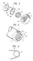
- Fig. 2 is a longitudinal sectional view showing the details of a photosensitive drum of Fig. 1;
- Fig. 3 is an exploded perspective view of a torque limiter incorporated into a gear as a driving means used with the photosensitive drum of Fig. 2;
- Fig. 4 is a perspective view of a flange portion of the photosensitive drum of Fig. 1; and
- Fig. 5 is a partial side view of a photosensitive belt according to another embodiment of an image bearing member.
- The present invention will now be explained in connection with preferred embodiments thereof with reference to the accompanying drawings.
- Fig. 1 shows a preferred embodiment of an image forming apparatus according to the present invention.
- The image forming apparatus shown in Fig. 1 comprises an electrophotographic
photosensitive drum 1 as an image bearing member, which is formed in a cylindrical shape and is rotated in a direction shown by an arrow in Fig. 1. Around the photosensitive drum, along the direction of rotation thereof, there are, in order, acharging device 2 for uniformly charging a peripheral surface of thephotosensitive drum 1; an information light beam 4 emitted from an exposure device (not shown) for performing an exposing operation in response to an image information, for example, by means of a laser optical system to form a latent image on thephotosensitive drum 1; a known developingdevice 6 for visualizing the latent image by applying a toner as a developer to the latent image formed on thephotosensitive drum 1; atransfer charging device 8 for transferring the visualized image from thephotosensitive drum 1 onto a transfer sheet P such as a paper; a knownfixing device 10 for fixing the image transferred to the transfer sheet P; and acleaning device 12 for cleaning the residual toner on thephotosensitive drum 1. Thecleaning device 12 includes atoner discharging member 13 for conveying the removed residual toner toward one end of thecleaning device 12, which member comprises, for example, a screw member. - Image forming processes carried out by the image forming apparatus having the construction mentioned above are well known in the art; and, thus, the detailed explanation regarding the image forming processes will be omitted here.
- Now, referring to Fig. 2 showing the details of a part of the
photosensitive drum 1, thephotosensitive drum 1 has aflange 14 fixed thereto, on an outer peripheral surface of which agear 14a for transmitting a driving force to thetoner discharging member 13 is formed. Theflange 14 is rotatably supported, at its central portion, by asupport shaft 16 rotatably mounted on aframe 15 of the image forming apparatus. Accordingly, thephotosensitive drum 1 is freely rotatably supported by theframe 15 through thesupport shaft 16. - Further, a substantially
cylindrical gear 17 acting as a driving means is fixed to thesupport shaft 16 coaxially therewith. As shown, acoil spring 18, a ring-shaped limiter plate 19 and a substantiallycircular driving plate 20 having a step (see Fig. 3) are incorporated in thegear 17 in a predetermined position, which elements 18-20 constitute atorque limiter 17A as a whole. Apin 20a protruded from thedriving plate 20 of thetorque limiter 17A toward theflange 14 can engage by one ofribs 14b (Fig. 4) formed in theflange 14. Thegear 14a formed on the peripheral surface of theflange 14 meshes with anidler gear 21 having asmall gear 21a fixed thereto, which meshes with adriving gear 23 for driving thetoner discharging member 13. - In addition, a
gear portion 17a formed on an outer peripheral surface of thegear 17 meshes with asleeve gear 25 fixed to a developingsleeve 24. - Now, the concrete construction of the
torque limiter 17A will be further explained. - As shown in Fig. 3, three
grooves 17b are formed in an inner peripheral surface of the substantiallycylindrical gear 17 acting as the driving means in predetermined positions, and thesegrooves 17a are engaged bycorresponding pawls 19b formed on an outer periphery of thelimiter plate 19 in predetermined positions; thus, when assembled, thelimiter plate 19 can be slidably moved along a central axis of thegear 17 while engaging by thegrooves 17b. Further, threetrapezoidal projections 19a are formed on an outer side surface of thelimiter plate 19 in predetermined positions, which projections are engaged by correspondingtrapezoidal recesses 20b formed in an inner side surface of thedriving plate 20. Thedriving plate 20 has an outer diameter that the driving plate is fitted in thegear 17. - With this construction, in the assembled condition (Fig. 2) that the
driving plate 20,limiter plate 19 andcoil spring 18 are positioned in place in thegear 17, when thegear 17 is drivingly rotated, thelimiter plate 19 tends to rotate against the load applied to thepin 20a of thedriving plate 20. In this case, since the rotational force from thelimiter plate 19 is transmitted to thedriving plate 20 through the engagement between theprojections 19a of thelimiter plate 19 and therecesses 20b of thedriving plate 20, an escaping force tending to escape thelimiter plate 19 along the inclined surfaces of thetrapezoidal recesses 20b of the driving plate is created. In this case, as long as the escaping force is smaller than a resultant force comprised of a friction force between thecoil spring 18 and thelimiter plate 19 and of a friction force between thetrapezoidal projections 19a and therecesses 20b, thelimiter plate 19 cannot escape from therecesses 20b and thus transmits the rotational force to thedriving plate 20. However, when the load applied to thepin 20a of thedriving plate 20 becomes larger, the escaping force will also become larger accordingly, and, consequently, if the escaping force exceeds the resultant force comprised of a friction force between thecoil spring 18 and thelimiter plate 19 and of a friction force between thetrapezoidal projections 19a and therecesses 20b, thelimiter plate 19 will escape from thetrapezoidal recesses 20b to slide inwardly along thegrooves 17b of thegear 17, thus not transmitting the rotational force to thedriving plate 20. This is the operating condition of thetorque limiter 17A. Of course, it should be noted that a torque value for creating the operation condition of thetorque limiter 17A can be properly set by appropriately selecting an angle of the inclined surface of the projection (and recess), coefficient of friction between the projection and recess, and the force of thecoil spring 18. - With the construction mentioned above, when the
support shaft 16 is rotated by the driving source (not shown), thegear 17 as the driving means is also rotated together with theshaft 16, thus driving the developingsleeve 24 in the developingdevice 6 and anagitating mechanism 6a (Fig. 1) in the developingdevice 6 through thesleeve gear 25. - Further, upon the rotation of the
gear 17, as shown in Figs. 2 and 3, the driving force is transmitted to thecoil spring 18,limiter plate 19,driving plate 20 andpin 20a in order, with the result that thepin 20a drivingly rotates theflange 14 and thephotosensitive drum 1 through the engagement between thepin 20a and therib 14b (Fig. 4) of theflange 14. In addition, since thegear 14a formed on the outer periphery of theflange 14 meshes with theidler gear 21, thedriving gear 23 for driving thetoner discharging member 13 for conveying the residual toner removed by the cleaner to the predetermined collection position is also rotated through theidler gear 21 and itssmall gear 21a. Accordingly, in this case, the load torques form thephotosensitive drum 1 and thetoner discharging member 13 are applied to thepin 20a of thetorque limiter 17A. - In this way, according to the illustrated embodiment of the present invention, since the
photosensitive drum 1 and the tonerdischarging member 13 are directly driven through the medium of thegear 17 acting as the driving means having the torque limiter of the above-mentioned construction, it is possible to set the torque value for initiating the operation of the torque limiter in high response to the abnormity in even the smaller load in the driving portions. - Further, as mentioned above, in the illustrated embodiment, it is possible to drive the developing
device 6 through the medium of thegear portion 17a formed on the outer periphery of thegear 17 acting as the driving means having thetorque limiter 17A, thus reducing the installation space of the driving mechanism and accordingly reducing the whole dimension of the image forming apparatus. - Now, as a numerical example, when the image forming apparatus according to the above-mentioned embodiment is used, if the load torque of the
photosensitive drum 1 and thetoner discharging member 13 is 4 ± 0.5 kg·cm, and the load torque of the developingdevice 6 is 4 ± 1.5 kg·cm, the load torques created when the toner container is filled with the toner can be detected by the torque limiter having the set torque value of 5 ± 0.5 kg·cm. In this case, it is possible to detect the abnormity with a maximum error of 2 kg·cm = ((5.5 - 3.5)kg·cm). - On the other hand, in the above-mentioned conventional image forming apparatus, the torque value of the torque limiter used must be set to 11 ± 1.1 kg· cm. In this case, the maximum error will be 6.1 kg·cm (=12.1 - 6)kg·cm, and therefore, the abnormity cannot be detected unless the load torque is increased by about 6 kg·cm due to the abnormity.
- In addition, with the above-mentioned construction of the illustrated embodiment, since the
photosensitive drum 1 is stopped immediately after the torque limiter is operated, when the torque limiter is operated (i.e., when the abnormity occurs), the image will be intermittently formed on the copying sheet, which clearly signals the abnormity to the operator. - It should be noted that the present invention is not limited to the illustrated embodiment wherein the torque limiter is assembled in the substantially cylindrical gear. For example, as an alternation, the torque limiter may be assembled in the
flange 14 of thephotosensitive drum 1. - Further, it is apparent that, in the present invention, the torque limiter does not depend upon the type thereof, but depends upon only the installation position thereof.
- Furthermore, the effect obtainable from the present invention does not depend upon the configuration of the photosensitive drum (image bearing member). For example, as shown in Fig. 5, even when an electrophotographic
photosensitive belt 1a entrained around a flange 26 (in place of theflange 14 of the drum) on which the torque limiter acts is used, a satisfactory effect can be obtained. - As mentioned above, according to the present invention, since the photosensitive drum as the image bearing member is driven by the gear acting as the driving means having the torque limiter arranged coaxially with the support shaft for the photosensitive drum and the driving gear for directly transmitting the driving force from the driving source in order to drive the developing device is associated with the first-mentioned gear, it is possible to set the torque value of the torque limiter in higher response to the photosensitive drum than in the conventional case, whereby the abnormity in the load torque of the photosensitive drum can be prematurely detected and can be signaled to the operator positively. Further, since the photosensitive drum and the developing device can be driven by the single driving mechanism, the whole dimension of the image forming apparatus can be considerably reduced.
- This invention relates to a driving mechanism for driving an electrophotographic photosensitive body operated through a torque limiter. The torque limiter is arranged on a support shaft for supporting the photosensitive body, thereby making the mechanism compact; and a driving gear for driving process means is arranged coaxially with the torque limiter independently of the latter, thereby reducing the load applied to the torque limiter, thus improving the ability of the torque limiter.
Claims (14)
a support shaft for rotatably supporting an image bearing member;
a driving source for drivingly rotating said support shaft;
a torque limiter mechanism driven by rotation of said support shaft; and
said image bearing member receiving a rotatable output portion of said torque limiter in the vicinity of said support shaft.
a support shaft for rotatably supporting an electrophotographic photosensitive body as an image bearing member;
a torque limiter mechanism provided between a driving source and a photosensitive drum constituting said photosensitive body and coaxially with said support shaft, for transmitting a rotational force from said driving source to said photosensitive drum; and
said photosensitive body including a driving force receiving portion for receiving an output of said torque limiter mechanism in the vicinity of said support shaft.
a support shaft for rotatably supporting an electrophotographic photosensitive body as an image bearing member;
a driving source for drivingly rotating said support shaft;
a first gear driven together with the rotation of said support shaft;
a torque limiter mechanism driven together with the rotation of said support shaft; and
said photosensitive body including a driving force receiving portion for receiving an output of said torque limiter mechanism in the vicinity of said support shaft.
Applications Claiming Priority (2)
| Application Number | Priority Date | Filing Date | Title |
|---|---|---|---|
| JP63038320A JP2711334B2 (en) | 1988-02-19 | 1988-02-19 | Image forming device |
| JP38320/88 | 1988-02-19 |
Publications (3)
| Publication Number | Publication Date |
|---|---|
| EP0329145A2 true EP0329145A2 (en) | 1989-08-23 |
| EP0329145A3 EP0329145A3 (en) | 1989-12-06 |
| EP0329145B1 EP0329145B1 (en) | 1994-12-07 |
Family
ID=12521994
Family Applications (1)
| Application Number | Title | Priority Date | Filing Date |
|---|---|---|---|
| EP89102695A Expired - Lifetime EP0329145B1 (en) | 1988-02-19 | 1989-02-16 | Apparatus for driving image bearing member |
Country Status (4)
| Country | Link |
|---|---|
| EP (1) | EP0329145B1 (en) |
| JP (1) | JP2711334B2 (en) |
| DE (1) | DE68919721T2 (en) |
| IT (1) | IT1230821B (en) |
Cited By (5)
| Publication number | Priority date | Publication date | Assignee | Title |
|---|---|---|---|---|
| EP0443461A2 (en) * | 1990-02-17 | 1991-08-28 | Canon Kabushiki Kaisha | Process cartridge and image forming apparatus usable with same |
| EP0538479A1 (en) * | 1991-04-10 | 1993-04-28 | Canon Kabushiki Kaisha | Process cartridge and method of assembling the process cartridge |
| EP0586033A2 (en) * | 1992-06-30 | 1994-03-09 | Canon Kabushiki Kaisha | Photosensitive drum, process cartridge, image forming apparatus and image forming system |
| EP0798602A2 (en) * | 1996-03-29 | 1997-10-01 | Xerox Corporation | Web feed printer drive system |
| US20190094796A1 (en) * | 2017-09-28 | 2019-03-28 | Canon Kabushiki Kaisha | Image forming apparatus |
Families Citing this family (2)
| Publication number | Priority date | Publication date | Assignee | Title |
|---|---|---|---|---|
| JPH0440244U (en) * | 1990-07-30 | 1992-04-06 | ||
| KR100544456B1 (en) | 2003-10-20 | 2006-01-24 | 삼성전자주식회사 | A gear assembly and a opc unit therewith |
Citations (2)
| Publication number | Priority date | Publication date | Assignee | Title |
|---|---|---|---|---|
| US4327992A (en) * | 1980-07-10 | 1982-05-04 | Apeco Corporation | Driving arrangement for photocopy machine |
| JPS60188627A (en) * | 1984-03-05 | 1985-09-26 | Konishiroku Photo Ind Co Ltd | Drive transmitting device for copying machine or the like |
Family Cites Families (3)
| Publication number | Priority date | Publication date | Assignee | Title |
|---|---|---|---|---|
| JPS60150567U (en) * | 1984-03-14 | 1985-10-05 | シャープ株式会社 | Toner amount detection device |
| JPS60247279A (en) * | 1984-05-22 | 1985-12-06 | Sanyo Electric Co Ltd | Electrophotographic copying machine |
| JPS62279355A (en) * | 1986-05-28 | 1987-12-04 | Konica Corp | Color image forming device |
-
1988
- 1988-02-19 JP JP63038320A patent/JP2711334B2/en not_active Expired - Fee Related
-
1989
- 1989-02-16 EP EP89102695A patent/EP0329145B1/en not_active Expired - Lifetime
- 1989-02-16 DE DE68919721T patent/DE68919721T2/en not_active Expired - Fee Related
- 1989-02-17 IT IT8947663A patent/IT1230821B/en active
Patent Citations (2)
| Publication number | Priority date | Publication date | Assignee | Title |
|---|---|---|---|---|
| US4327992A (en) * | 1980-07-10 | 1982-05-04 | Apeco Corporation | Driving arrangement for photocopy machine |
| JPS60188627A (en) * | 1984-03-05 | 1985-09-26 | Konishiroku Photo Ind Co Ltd | Drive transmitting device for copying machine or the like |
Non-Patent Citations (1)
| Title |
|---|
| PATENT ABSTRACTS OF JAPAN, vol. 10, no. 33 (M-452)(2090) 8 February 1986; & JP-A-60 188 627 (KONISHIROKU SHASHIN KOGYO K.K.) 26-09-1985 * |
Cited By (16)
| Publication number | Priority date | Publication date | Assignee | Title |
|---|---|---|---|---|
| EP0443461A3 (en) * | 1990-02-17 | 1992-05-20 | Canon Kabushiki Kaisha | Process cartridge and image forming apparatus usable with same |
| EP0443461A2 (en) * | 1990-02-17 | 1991-08-28 | Canon Kabushiki Kaisha | Process cartridge and image forming apparatus usable with same |
| US5581328A (en) * | 1991-04-10 | 1996-12-03 | Canon Kabushiki Kaisha | Process cartridge having connectable first and second frames and a recording apparatus using such a process cartridge |
| EP0538479A1 (en) * | 1991-04-10 | 1993-04-28 | Canon Kabushiki Kaisha | Process cartridge and method of assembling the process cartridge |
| EP0538479A4 (en) * | 1991-04-10 | 1994-02-16 | Canon Kabushiki Kaisha | |
| US5745824A (en) * | 1991-04-10 | 1998-04-28 | Canon Kabushiki Kaisha | Connecting part feature for a process cartridge |
| US5450166A (en) * | 1991-04-10 | 1995-09-12 | Canon Kabushiki Kaisha | Process cartridge, recording apparatus, and method for assembling process cartridge |
| US5602623A (en) * | 1992-06-30 | 1997-02-11 | Canon Kabushiki Kaisha | Photosensitive drum provided in an image forming apparatus including gears disposed at an end of drum |
| EP0586033A3 (en) * | 1992-06-30 | 1994-04-06 | Canon Kabushiki Kaisha | Photosensitive drum, process cartridge, image forming apparatus and image forming system |
| EP0813119A1 (en) * | 1992-06-30 | 1997-12-17 | Canon Kabushiki Kaisha | Photosensitive drum, process cartridge, image forming apparatus and image forming system |
| EP0586033A2 (en) * | 1992-06-30 | 1994-03-09 | Canon Kabushiki Kaisha | Photosensitive drum, process cartridge, image forming apparatus and image forming system |
| US5926672A (en) * | 1992-06-30 | 1999-07-20 | Canon Kabushiki Kaisha | Photosensitive drum provided in an image forming apparatus including helical gears disposed at an end of the drum |
| EP0798602A2 (en) * | 1996-03-29 | 1997-10-01 | Xerox Corporation | Web feed printer drive system |
| EP0798602A3 (en) * | 1996-03-29 | 1998-06-03 | Xerox Corporation | Web feed printer drive system |
| US20190094796A1 (en) * | 2017-09-28 | 2019-03-28 | Canon Kabushiki Kaisha | Image forming apparatus |
| US10571858B2 (en) * | 2017-09-28 | 2020-02-25 | Canon Kabushiki Kaisha | Image forming apparatus and configuration of cartridge unit |
Also Published As
| Publication number | Publication date |
|---|---|
| DE68919721D1 (en) | 1995-01-19 |
| DE68919721T2 (en) | 1995-05-18 |
| JPH01211773A (en) | 1989-08-24 |
| JP2711334B2 (en) | 1998-02-10 |
| IT1230821B (en) | 1991-11-07 |
| EP0329145A3 (en) | 1989-12-06 |
| EP0329145B1 (en) | 1994-12-07 |
| IT8947663A0 (en) | 1989-02-17 |
Similar Documents
| Publication | Publication Date | Title |
|---|---|---|
| US7103308B2 (en) | Developer cartridge and image forming apparatus | |
| US5303004A (en) | Apparatus for driving image bearing member via torque limiter | |
| EP0331324B1 (en) | Image forming apparatus usable with process cartridge detachably mountable thereto | |
| EP0564793B1 (en) | Image-forming machine | |
| CN108241274B (en) | Clutch device, process cartridge, and image forming apparatus | |
| JP2593315Y2 (en) | Developing device | |
| EP0329145B1 (en) | Apparatus for driving image bearing member | |
| US4586813A (en) | Image forming apparatus | |
| US5280224A (en) | Process cartridge drive mechanism and image forming apparatus | |
| JP2000162945A (en) | Processing cartridge and image forming device | |
| JP2000066556A (en) | Waste toner carrying device and image forming device | |
| JP3512862B2 (en) | Gearing | |
| US4330198A (en) | Magnetic brush developing device for electrostatic copying apparatus | |
| JP3673642B2 (en) | Fixing device | |
| KR100202410B1 (en) | Agitator driving method | |
| JPS62228715A (en) | Drive transmission device of recording device or the like | |
| JPH0545949A (en) | Image forming device | |
| KR100260430B1 (en) | Driving gear for developing in electrophotographic processor | |
| JPS6320992Y2 (en) | ||
| JP3935630B2 (en) | Image forming apparatus | |
| JPH07117801B2 (en) | Toner transport mechanism and process cartridge | |
| JPS61141475A (en) | Image forming device | |
| JPS62127785A (en) | Mounting method for photosensitive drum | |
| JP2005128137A (en) | Image forming apparatus | |
| JPH0580651A (en) | Image forming device and process cartridge |
Legal Events
| Date | Code | Title | Description |
|---|---|---|---|
| PUAI | Public reference made under article 153(3) epc to a published international application that has entered the european phase |
Free format text: ORIGINAL CODE: 0009012 |
|
| AK | Designated contracting states |
Kind code of ref document: A2 Designated state(s): DE FR GB |
|
| PUAL | Search report despatched |
Free format text: ORIGINAL CODE: 0009013 |
|
| AK | Designated contracting states |
Kind code of ref document: A3 Designated state(s): DE FR GB |
|
| 17P | Request for examination filed |
Effective date: 19900423 |
|
| 17Q | First examination report despatched |
Effective date: 19920629 |
|
| GRAA | (expected) grant |
Free format text: ORIGINAL CODE: 0009210 |
|
| AK | Designated contracting states |
Kind code of ref document: B1 Designated state(s): DE FR GB |
|
| REF | Corresponds to: |
Ref document number: 68919721 Country of ref document: DE Date of ref document: 19950119 |
|
| ET | Fr: translation filed | ||
| PLBE | No opposition filed within time limit |
Free format text: ORIGINAL CODE: 0009261 |
|
| STAA | Information on the status of an ep patent application or granted ep patent |
Free format text: STATUS: NO OPPOSITION FILED WITHIN TIME LIMIT |
|
| 26N | No opposition filed | ||
| REG | Reference to a national code |
Ref country code: GB Ref legal event code: IF02 |
|
| PGFP | Annual fee paid to national office [announced via postgrant information from national office to epo] |
Ref country code: DE Payment date: 20070208 Year of fee payment: 19 |
|
| PGFP | Annual fee paid to national office [announced via postgrant information from national office to epo] |
Ref country code: GB Payment date: 20070214 Year of fee payment: 19 |
|
| PGFP | Annual fee paid to national office [announced via postgrant information from national office to epo] |
Ref country code: FR Payment date: 20070208 Year of fee payment: 19 |
|
| GBPC | Gb: european patent ceased through non-payment of renewal fee |
Effective date: 20080216 |
|
| REG | Reference to a national code |
Ref country code: FR Ref legal event code: ST Effective date: 20081031 |
|
| PG25 | Lapsed in a contracting state [announced via postgrant information from national office to epo] |
Ref country code: DE Free format text: LAPSE BECAUSE OF NON-PAYMENT OF DUE FEES Effective date: 20080902 |
|
| PG25 | Lapsed in a contracting state [announced via postgrant information from national office to epo] |
Ref country code: FR Free format text: LAPSE BECAUSE OF NON-PAYMENT OF DUE FEES Effective date: 20080229 |
|
| PG25 | Lapsed in a contracting state [announced via postgrant information from national office to epo] |
Ref country code: GB Free format text: LAPSE BECAUSE OF NON-PAYMENT OF DUE FEES Effective date: 20080216 |