EP0327249A2 - Apparatus for knee prosthesis - Google Patents
Apparatus for knee prosthesis Download PDFInfo
- Publication number
- EP0327249A2 EP0327249A2 EP89300706A EP89300706A EP0327249A2 EP 0327249 A2 EP0327249 A2 EP 0327249A2 EP 89300706 A EP89300706 A EP 89300706A EP 89300706 A EP89300706 A EP 89300706A EP 0327249 A2 EP0327249 A2 EP 0327249A2
- Authority
- EP
- European Patent Office
- Prior art keywords
- arm
- cutting
- distal
- femoral
- guide
- Prior art date
- Legal status (The legal status is an assumption and is not a legal conclusion. Google has not performed a legal analysis and makes no representation as to the accuracy of the status listed.)
- Granted
Links
Images


Classifications
-
- A—HUMAN NECESSITIES
- A61—MEDICAL OR VETERINARY SCIENCE; HYGIENE
- A61B—DIAGNOSIS; SURGERY; IDENTIFICATION
- A61B17/00—Surgical instruments, devices or methods, e.g. tourniquets
- A61B17/16—Bone cutting, breaking or removal means other than saws, e.g. Osteoclasts; Drills or chisels for bones; Trepans
- A61B17/1662—Bone cutting, breaking or removal means other than saws, e.g. Osteoclasts; Drills or chisels for bones; Trepans for particular parts of the body
- A61B17/1675—Bone cutting, breaking or removal means other than saws, e.g. Osteoclasts; Drills or chisels for bones; Trepans for particular parts of the body for the knee
- A61B17/1677—Bone cutting, breaking or removal means other than saws, e.g. Osteoclasts; Drills or chisels for bones; Trepans for particular parts of the body for the knee for the patella
-
- A—HUMAN NECESSITIES
- A61—MEDICAL OR VETERINARY SCIENCE; HYGIENE
- A61B—DIAGNOSIS; SURGERY; IDENTIFICATION
- A61B17/00—Surgical instruments, devices or methods, e.g. tourniquets
- A61B17/14—Surgical saws ; Accessories therefor
- A61B17/15—Guides therefor
- A61B17/154—Guides therefor for preparing bone for knee prosthesis
-
- A—HUMAN NECESSITIES
- A61—MEDICAL OR VETERINARY SCIENCE; HYGIENE
- A61B—DIAGNOSIS; SURGERY; IDENTIFICATION
- A61B17/00—Surgical instruments, devices or methods, e.g. tourniquets
- A61B17/16—Bone cutting, breaking or removal means other than saws, e.g. Osteoclasts; Drills or chisels for bones; Trepans
- A61B17/17—Guides or aligning means for drills, mills, pins or wires
- A61B17/1739—Guides or aligning means for drills, mills, pins or wires specially adapted for particular parts of the body
- A61B17/1764—Guides or aligning means for drills, mills, pins or wires specially adapted for particular parts of the body for the knee
- A61B17/1767—Guides or aligning means for drills, mills, pins or wires specially adapted for particular parts of the body for the knee for the patella
-
- A—HUMAN NECESSITIES
- A61—MEDICAL OR VETERINARY SCIENCE; HYGIENE
- A61F—FILTERS IMPLANTABLE INTO BLOOD VESSELS; PROSTHESES; DEVICES PROVIDING PATENCY TO, OR PREVENTING COLLAPSING OF, TUBULAR STRUCTURES OF THE BODY, e.g. STENTS; ORTHOPAEDIC, NURSING OR CONTRACEPTIVE DEVICES; FOMENTATION; TREATMENT OR PROTECTION OF EYES OR EARS; BANDAGES, DRESSINGS OR ABSORBENT PADS; FIRST-AID KITS
- A61F2/00—Filters implantable into blood vessels; Prostheses, i.e. artificial substitutes or replacements for parts of the body; Appliances for connecting them with the body; Devices providing patency to, or preventing collapsing of, tubular structures of the body, e.g. stents
- A61F2/02—Prostheses implantable into the body
- A61F2/30—Joints
- A61F2/46—Special tools or methods for implanting or extracting artificial joints, accessories, bone grafts or substitutes, or particular adaptations therefor
- A61F2/4603—Special tools or methods for implanting or extracting artificial joints, accessories, bone grafts or substitutes, or particular adaptations therefor for insertion or extraction of endoprosthetic joints or of accessories thereof
- A61F2/461—Special tools or methods for implanting or extracting artificial joints, accessories, bone grafts or substitutes, or particular adaptations therefor for insertion or extraction of endoprosthetic joints or of accessories thereof of knees
-
- A—HUMAN NECESSITIES
- A61—MEDICAL OR VETERINARY SCIENCE; HYGIENE
- A61B—DIAGNOSIS; SURGERY; IDENTIFICATION
- A61B17/00—Surgical instruments, devices or methods, e.g. tourniquets
- A61B17/02—Surgical instruments, devices or methods, e.g. tourniquets for holding wounds open; Tractors
- A61B17/025—Joint distractors
-
- A—HUMAN NECESSITIES
- A61—MEDICAL OR VETERINARY SCIENCE; HYGIENE
- A61B—DIAGNOSIS; SURGERY; IDENTIFICATION
- A61B17/00—Surgical instruments, devices or methods, e.g. tourniquets
- A61B17/14—Surgical saws ; Accessories therefor
- A61B17/15—Guides therefor
- A61B17/154—Guides therefor for preparing bone for knee prosthesis
- A61B17/155—Cutting femur
-
- A—HUMAN NECESSITIES
- A61—MEDICAL OR VETERINARY SCIENCE; HYGIENE
- A61B—DIAGNOSIS; SURGERY; IDENTIFICATION
- A61B17/00—Surgical instruments, devices or methods, e.g. tourniquets
- A61B17/14—Surgical saws ; Accessories therefor
- A61B17/15—Guides therefor
- A61B17/154—Guides therefor for preparing bone for knee prosthesis
- A61B17/157—Cutting tibia
-
- A—HUMAN NECESSITIES
- A61—MEDICAL OR VETERINARY SCIENCE; HYGIENE
- A61B—DIAGNOSIS; SURGERY; IDENTIFICATION
- A61B17/00—Surgical instruments, devices or methods, e.g. tourniquets
- A61B17/14—Surgical saws ; Accessories therefor
- A61B17/15—Guides therefor
- A61B17/154—Guides therefor for preparing bone for knee prosthesis
- A61B17/158—Cutting patella
-
- A—HUMAN NECESSITIES
- A61—MEDICAL OR VETERINARY SCIENCE; HYGIENE
- A61B—DIAGNOSIS; SURGERY; IDENTIFICATION
- A61B17/00—Surgical instruments, devices or methods, e.g. tourniquets
- A61B17/16—Bone cutting, breaking or removal means other than saws, e.g. Osteoclasts; Drills or chisels for bones; Trepans
- A61B17/1604—Chisels; Rongeurs; Punches; Stamps
- A61B17/1606—Chisels; Rongeurs; Punches; Stamps of forceps type, i.e. having two jaw elements moving relative to each other
-
- A—HUMAN NECESSITIES
- A61—MEDICAL OR VETERINARY SCIENCE; HYGIENE
- A61B—DIAGNOSIS; SURGERY; IDENTIFICATION
- A61B17/00—Surgical instruments, devices or methods, e.g. tourniquets
- A61B17/56—Surgical instruments or methods for treatment of bones or joints; Devices specially adapted therefor
- A61B17/58—Surgical instruments or methods for treatment of bones or joints; Devices specially adapted therefor for osteosynthesis, e.g. bone plates, screws, setting implements or the like
- A61B17/88—Osteosynthesis instruments; Methods or means for implanting or extracting internal or external fixation devices
- A61B17/885—Tools for expanding or compacting bones or discs or cavities therein
-
- A—HUMAN NECESSITIES
- A61—MEDICAL OR VETERINARY SCIENCE; HYGIENE
- A61B—DIAGNOSIS; SURGERY; IDENTIFICATION
- A61B17/00—Surgical instruments, devices or methods, e.g. tourniquets
- A61B17/02—Surgical instruments, devices or methods, e.g. tourniquets for holding wounds open; Tractors
- A61B17/025—Joint distractors
- A61B2017/0268—Joint distractors for the knee
-
- A—HUMAN NECESSITIES
- A61—MEDICAL OR VETERINARY SCIENCE; HYGIENE
- A61B—DIAGNOSIS; SURGERY; IDENTIFICATION
- A61B17/00—Surgical instruments, devices or methods, e.g. tourniquets
- A61B17/16—Bone cutting, breaking or removal means other than saws, e.g. Osteoclasts; Drills or chisels for bones; Trepans
- A61B2017/1602—Mills
-
- A—HUMAN NECESSITIES
- A61—MEDICAL OR VETERINARY SCIENCE; HYGIENE
- A61F—FILTERS IMPLANTABLE INTO BLOOD VESSELS; PROSTHESES; DEVICES PROVIDING PATENCY TO, OR PREVENTING COLLAPSING OF, TUBULAR STRUCTURES OF THE BODY, e.g. STENTS; ORTHOPAEDIC, NURSING OR CONTRACEPTIVE DEVICES; FOMENTATION; TREATMENT OR PROTECTION OF EYES OR EARS; BANDAGES, DRESSINGS OR ABSORBENT PADS; FIRST-AID KITS
- A61F2/00—Filters implantable into blood vessels; Prostheses, i.e. artificial substitutes or replacements for parts of the body; Appliances for connecting them with the body; Devices providing patency to, or preventing collapsing of, tubular structures of the body, e.g. stents
- A61F2/02—Prostheses implantable into the body
- A61F2/30—Joints
- A61F2/30721—Accessories
- A61F2/30723—Plugs or restrictors for sealing a cement-receiving space
-
- A—HUMAN NECESSITIES
- A61—MEDICAL OR VETERINARY SCIENCE; HYGIENE
- A61F—FILTERS IMPLANTABLE INTO BLOOD VESSELS; PROSTHESES; DEVICES PROVIDING PATENCY TO, OR PREVENTING COLLAPSING OF, TUBULAR STRUCTURES OF THE BODY, e.g. STENTS; ORTHOPAEDIC, NURSING OR CONTRACEPTIVE DEVICES; FOMENTATION; TREATMENT OR PROTECTION OF EYES OR EARS; BANDAGES, DRESSINGS OR ABSORBENT PADS; FIRST-AID KITS
- A61F2/00—Filters implantable into blood vessels; Prostheses, i.e. artificial substitutes or replacements for parts of the body; Appliances for connecting them with the body; Devices providing patency to, or preventing collapsing of, tubular structures of the body, e.g. stents
- A61F2/02—Prostheses implantable into the body
- A61F2/30—Joints
- A61F2/38—Joints for elbows or knees
- A61F2/3877—Patellae or trochleae
-
- A—HUMAN NECESSITIES
- A61—MEDICAL OR VETERINARY SCIENCE; HYGIENE
- A61F—FILTERS IMPLANTABLE INTO BLOOD VESSELS; PROSTHESES; DEVICES PROVIDING PATENCY TO, OR PREVENTING COLLAPSING OF, TUBULAR STRUCTURES OF THE BODY, e.g. STENTS; ORTHOPAEDIC, NURSING OR CONTRACEPTIVE DEVICES; FOMENTATION; TREATMENT OR PROTECTION OF EYES OR EARS; BANDAGES, DRESSINGS OR ABSORBENT PADS; FIRST-AID KITS
- A61F2/00—Filters implantable into blood vessels; Prostheses, i.e. artificial substitutes or replacements for parts of the body; Appliances for connecting them with the body; Devices providing patency to, or preventing collapsing of, tubular structures of the body, e.g. stents
- A61F2/02—Prostheses implantable into the body
- A61F2/30—Joints
- A61F2/46—Special tools or methods for implanting or extracting artificial joints, accessories, bone grafts or substitutes, or particular adaptations therefor
- A61F2/4603—Special tools or methods for implanting or extracting artificial joints, accessories, bone grafts or substitutes, or particular adaptations therefor for insertion or extraction of endoprosthetic joints or of accessories thereof
- A61F2/4614—Special tools or methods for implanting or extracting artificial joints, accessories, bone grafts or substitutes, or particular adaptations therefor for insertion or extraction of endoprosthetic joints or of accessories thereof of plugs for sealing a cement-receiving space
-
- A—HUMAN NECESSITIES
- A61—MEDICAL OR VETERINARY SCIENCE; HYGIENE
- A61F—FILTERS IMPLANTABLE INTO BLOOD VESSELS; PROSTHESES; DEVICES PROVIDING PATENCY TO, OR PREVENTING COLLAPSING OF, TUBULAR STRUCTURES OF THE BODY, e.g. STENTS; ORTHOPAEDIC, NURSING OR CONTRACEPTIVE DEVICES; FOMENTATION; TREATMENT OR PROTECTION OF EYES OR EARS; BANDAGES, DRESSINGS OR ABSORBENT PADS; FIRST-AID KITS
- A61F2/00—Filters implantable into blood vessels; Prostheses, i.e. artificial substitutes or replacements for parts of the body; Appliances for connecting them with the body; Devices providing patency to, or preventing collapsing of, tubular structures of the body, e.g. stents
- A61F2/02—Prostheses implantable into the body
- A61F2/28—Bones
- A61F2002/2835—Bone graft implants for filling a bony defect or an endoprosthesis cavity, e.g. by synthetic material or biological material
- A61F2002/2839—Bone plugs or bone graft dowels
-
- A—HUMAN NECESSITIES
- A61—MEDICAL OR VETERINARY SCIENCE; HYGIENE
- A61F—FILTERS IMPLANTABLE INTO BLOOD VESSELS; PROSTHESES; DEVICES PROVIDING PATENCY TO, OR PREVENTING COLLAPSING OF, TUBULAR STRUCTURES OF THE BODY, e.g. STENTS; ORTHOPAEDIC, NURSING OR CONTRACEPTIVE DEVICES; FOMENTATION; TREATMENT OR PROTECTION OF EYES OR EARS; BANDAGES, DRESSINGS OR ABSORBENT PADS; FIRST-AID KITS
- A61F2/00—Filters implantable into blood vessels; Prostheses, i.e. artificial substitutes or replacements for parts of the body; Appliances for connecting them with the body; Devices providing patency to, or preventing collapsing of, tubular structures of the body, e.g. stents
- A61F2/02—Prostheses implantable into the body
- A61F2/30—Joints
- A61F2/46—Special tools or methods for implanting or extracting artificial joints, accessories, bone grafts or substitutes, or particular adaptations therefor
- A61F2/4603—Special tools or methods for implanting or extracting artificial joints, accessories, bone grafts or substitutes, or particular adaptations therefor for insertion or extraction of endoprosthetic joints or of accessories thereof
- A61F2002/4622—Special tools or methods for implanting or extracting artificial joints, accessories, bone grafts or substitutes, or particular adaptations therefor for insertion or extraction of endoprosthetic joints or of accessories thereof having the shape of a forceps or a clamp
Definitions
- the present invention relates to apparatus for a knee prosthesis. More particularly the invention is concerned with a modular apparatus for use in the preparation of bone surfaces and the implantation of a modular total knee prosthesis.
- the human knee joint is subject to greater stress than any joint in the body. This is because it must bear the full weight of the body, often at disadvantageous leverage ratios. Consequently, there is a premium on the design of a prosthesis for replacement of the knee joint.
- the implantation of a prosthesis should avoid resection of any more of the joint than is strictly necessary. This is especially true of the knee which includes ligaments within the joint, i.e., the cruciate ligaments which are important for the future functioning of the joint, and, therefore, in the design of the prosthesis it is important to keep the thickness of the prosthesis to a minimum so as to avoid resection, but yet to do so without sacrificing consistent and long term adequate performance.
- knee prosthesis Other factors to be considered in the design of a knee prosthesis include the need to anchor it against the forces of shear, tipping, and torque to which the knee joint is particularly susceptible.
- Application Serial No. 52033 provides a tibial component and application Serial No. 97286 provides, in combination, a femoral component and tibial plateau.
- the disclosures in both these applications are incorporated herein by reference.
- the present invention is concerned with improved instrumentation to facilitate implantation of a total knee prosthesis such as disclosed in (but not limited to) the aforementioned applications.
- a modular apparatus for use in the preparation of bone surfaces and the implantation of a modular total knee prosthesis in a patient which apparatus comprises:
- the total apparatus defined above is a novel and unique combination of numerous elements some of which are novel per se and some of which are modified and improved versions of instruments which performed similar functions in the prior art.
- the overall effect of the present novel combination apparatus is to facilitate bone preparation and prosthesis implantation and also provide a degree of modularity hitherto unknown.
- the apparatus is particularly adapted for use with the improved prostheses disclosed in the copending applications acknowledged hereinabove and the invention will be more particularly described with reference to the implantation of preferred embodiments of such prostheses.
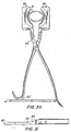
- Figure 1 illustrates an instrument for the correct alignment of a cutting surface to facilitate the resection of a tibial plateau 43 (see Figure 43) to receive a tibial implant, which instrument comprises an extendable rod 10′ having a hollow distal portion 2 and a solid proximal portion 3, said distal portion comprising a hollow cylindrical tube 2 and said proximal portion comprising a solid cylindrical rod 3 which slidably fits within said hollow cylindrical tube and means for locking the slidable rod within said tube when the desired overall length is achieved.
- an extendable rod 10′ having a hollow distal portion 2 and a solid proximal portion 3, said distal portion comprising a hollow cylindrical tube 2 and said proximal portion comprising a solid cylindrical rod 3 which slidably fits within said hollow cylindrical tube and means for locking the slidable rod within said tube when the desired overall length is achieved.
- said means for locking the slidable solid rod 3 within the hollow cylindrical tube 2 comprises a locking screw 4 which tightens within a groove 5 extending longitudinally along said solid rod, the locking preventing both rotational and longitudinal movement.
- the proximal end of the solid rod has a predetermined radius of curvature R and terminates in an integral cutting platform 6 defining a flat cutting surface 1.
- the distal end of said hollow cylindrical tube terminates in a bearing 7 which slides radially along a rail 8 extending substantially perpendicularly from a flat plate 9 located in a groove 10 within which said plate may slide laterally, said groove being integral with a pair of tension spring clamping jaws 11, said radial and lateral sliding movement providing means for correctly aligning said cutting platform close to the tibial plateau.
- Each of the jaws 11 open and close about a pivot 12 at the end of an arm 13 and is held in a gripping position by a tension spring 14.
- the cutting platform 6 has an improved slim configuration and an inner curved profile 15 adapted to fit against the tibia. It also has a central hole 16 adapted to accept the peg 17 of a stylus holder ( Figure 5) and holes 18 to accept location pins.
- the distal portion of the instrument illustrated in Figure 1 also carries a solid site guide 19 having a 5° site for correctly aligning the instrument relative to the tibia of a patient.
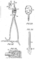
- Figure 5 illustrates an adjustable stylus 20 for use in combination with the cutting platform 6 of the instrument illustrated in Figures 1-3, which comprises a solid base portion 21 having an extending peg adapted to be located in a cooperating hole in said cutting platform 6 to mount said base portion upon said cutting platform, an arm 22 extending upwardly and at an angle from said base, said arm having a distal end with a female screw thread 23 therein, and a stylus arm 20 having a distal end and a proximal end with a male screw thread 24, said male screw thread of the stylus arm being mated with the female screw thread of the upwardly extending arm, so that when the distal end of the stylus arm touches the tibial plateau 43 the cutting platform may be locked in its correct alignment for resection of the plateau and the stylus arm may then be withdrawn by unscrewing at its proximal end without disturbing the alignment of the cutting platform.
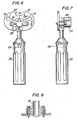
- Figures 6 to 8 illustrate a modular stem/fin template 25 for determining the peripheral size of a resected proximal tibia comprising a handle 26 carrying the template.
- the handle has a hole 26′ which enables it to be slidably mounted on an alignment rod (see Figures 44 and 45).
- the template which may come in different sizes according to size of the tibia has a cut out portion 27 to accommodate the cruciate ligaments, and comprises a solid flat plate 25 defining the periphery of the resected proximal tibia, a raised cylindrical hollow tube 28 comprising a circular hole 29 to accept a stem punch ( Figure 9) and slots 30 radiating from said hole to accept a fin punch for aligning a stem/fin punch and also including an enlarged circular hole 31 for a drill around the end of each fin slot distal from said stem hole.
- Figures 9 and 10 illustrate a stem/fin punch 32 comprising a central hollow cylindrical tube 33 with a distal chisel edge 34 and two fins 35 extending radially from said tube at a predetermined angle and each having a distal chisel edge.
- the proximal end of the punch terminates in a circular plate 37 adapted to be struck by a surgeon's mallet for punching out the bone to receive the stem and fins of a tibial implant.
- the side of the cylindrical tube has a slot 38 into which a projecting peg 39 ( Figure 7) in the raised cylindrical hollow tube of the template may key thereby ensuring proper alignment of the punch within the template.
- Figure 11 illustrates a solid push rod 40 which fits into the hollow cylindrical tube of the stem/fin punch.
- Figures 12 to 14 illustrate an alignment fork 41 attached to an intramedullary rod 42 adapted to be introduced into a medullary canal of the patient;
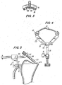
- Figures 15 to 17 illustrate a femoral distractor comprising a handle 44 having a vertical hole 45 there through for accomodating an alignment rod (not shown) a rail 47 adapted to slide onto an alignment fork, a lateral arm 48 and a medial arm 49.
- Each arm may be separately raised or lowered by a rack and pinion mechanism 50, operated by a turn key 51.
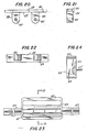
- Figures 18 and 19 illustrate a drill guide 52 having a bottom groove 53 adapted to slide along the rail of the femoral distractor and having a plurality of holes 54 for accepting locating pins (not shown).
- Figures 20 to 22 illustrate a distal cutting guide comprising a flat plate 55 having a top cutting surface 56 and a bottom surface 57 and integral flanges 58 extending from said bottom surface and each being inset 59 from one edge thereof, each of said flanges having a locating hole 60 extending therethrough.
- Figures 23 and 24 illustrate a modular cutting guide for guiding a saw blade to make cuts required for a femoral component of a total knee prosthesis, comprising a substantially rectangular frame 61 having a top wall whose outer surface provides a flat top cutting surface 62 and a bottom wall whose outer surface provides a flat bottom cutting surface 63 and, located between said top surface and said bottom surface, an intermediate solid block 64 having an angled top surface 65 and an angled bottom surface 66, each of said angled surfaces providing a guide for making a chamfer cut.
- the open gaps 64′ between the angled top surface 65 and the inner surface of the top wall and between the angled bottom surface 66 and the inner surface of the bottom wall providing windows which enable the surgeon to have a clear view of the surfaces being cut.
- the intermediate solid cutting block carries pegs 67′ for locating the guide in predrilled holes on the femur. The guide is held by handles 67 projecting from the sides of the block.
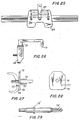
- Figures 25 and 26 illustrate a femoral sizer for determining the size of a patient's femur to prepare it for resection to receive a modular femoral prosthesis comprising a body portion 68 having locating holes, a central tubular orifice 69 for accepting a feeler element 70 and indicating means for indicating the depth of the feeler element within said orifice when the sizer 71 is located on the patient's femur, thereby providing a determination of the size required for a modular cutting guide.
- Figures 27 and 28 illustrate a reamer guide for correct location of a reamer (Figure 29) for preparing a cavity to locate a femoral prosthesis peg, which reamer guide comprises a flat plate 72 having a top surface 73 and a bottom surface 74, a hole 75 extending through the plate, a tubular bushing 76 extending from said top surface and lined up with said hole and locating pegs 77 extending from said bottom surface.
- Figure 29 illustrates a reamer having cutting edges 78 for reaming a cavity to accept the stem of a femoral component prosthesis.
- Figures 30 and 31 illustrate a patella resection guide comprising a scissor-type clamp 79 having distal gripping arms 80, each of said arms defining a cutting surface and gripping teeth 81, said gripping teeth being inset 82 below the plane 83 of the associated cutting surface.
- the proximal end of the device has a ratchet arm 84′ to prevent the clamp from slipping.
- FIGS 32, 33, 35, 36 and 37 illustrate a patella handling instrument having an interchangeable modular template and clamp, comprising a scissor-type member 84 having a first pivotal arm 85 with a distal end and a second pivotal arm 86 with a distal end, said first arm having a swivable platform 87 located at its distal end, the surface 88 of said platform facing inwardly toward said second arm and said second arm having means 89 to interchangeably grip and hold either:- (i) a modular patella template 90 having holes to accept drills, or (ii) a clamp-member 91 adapted to clamp a patella prosthesis to a resected patella.
- the preferred means for interchanging the template and the clamp member is a quick-connect device illustrated in detail in Figure 35.
- the quick connect device comprises a compression spring 92, a ball 93, a coupling 94 and a retaining ring 95.
- Figure 34 illustrates a drill bit 96 with a chisel edge 97 and a stop 98 for drill holes in a patella using the template illustrated in figure 33.
- Figures 38 to 40 illustrate a femoral stabilizer box chisel for excavating a bone to accept a posterior stabilized femoral component which comprises a handle 99, a anterior skid 100 extending from said handle and a box chisel 101 extending parallel to said locator housing and having a cutting profile for cutting the required cavity to accept the peg of the stabilized component.
- the patient's knee is flexed past 90° and the tibia is drawn forward.
- the lower clamp arms 11 of the upper tibial cutting guide 6 are opened and clamped around the ankle joint proximal to the medial malleolas.
- the distal end has two adjustments, one each for anterior/posterior (A/P) and medial/lateral (M/L).
- the alignment tube 2 may be shifted about 2.5 mm. to compensate for the presence of the fibula.
- the tube is slid along the A/P rail 8 to a specified mark to establish a 3°-5° posterior slope.
- the site guide 19 on the anterior surface of the tube serves as a visual aid.
- the level of the cutting platform is positioned relative to the lowest point on the tibial plateau using the tibial stylus as a guide. Two 1/8" pins are used to fix the cutting platform to the proximal tibia so that accurate bone cuts can be made.
- the curvature R in the rod which connects the cutting platform to the alignment tube mimics the posterior angulation of the proximal tibia. This positions the cutting platform close to the tibial plateau and will allow a standard sized saw blade to cut the entire surface of the proximal tibia.
- the cutting platform is contoured to match the curvature of the anterior tibial plateau.
- the peripheral size of the resected proximal tibia is determined using the stem/fin punch templates ( Figures 44 and 45). The size which best covers the peripheral cortical rim is chosen.
- rotational alignment of the template is established by lining up the alignment rod and tibial shaft in the frontal plane. The two captured pins are tapped into the proximal tibia to secure the template.
- the appropriate sized stem/fin punch is chosen and introduced into the cylindrical projection on the template. Rotational orientation of the punch is established by engaging the wings within the slots in the cylinder. Using a mallet the punch is driven into the tibia until the driving platform bottoms on the top of the cylinder.
- the lateral anterior prominence is resected from the distal femur for better seating of the distal femoral cutting block to be used later.
- a 5/16" (8 mm) starter hole is drilled in line with the medullary canal.
- the location of the drill hole should be midway between the medial and lateral femoral condyles just anterior to the origin of the posterior cruciate.
- the direction of the drill bit should be in line with the longitudinaly axis of the femur in both planes.
- the right or left alignment fork is introduced into the medullary canal ( Figures 46).
- the femoral distractor is slid onto the alignment fork and the leg extended ( Figure 47).
- the distractor is now keyed to the femur at the appropriate angle of valgus from the mechanical axis in the frontal plane and perpendicular in the sagittal plane.
- the hole for the central stem is prepared once the trial is in place by inserting the peg reamer through the central hole in the pegreamer guide which is positioned on the femoral trial, see Figure 53, and reaming to the appropriate depth which is determined by a marking, for example a stop 78′, on the reamer.
- the bone must be excavated to prepare a site for the stabilizer box.
- Choose the appropriate size stabilizer chisel (Figure 40). Rest the anterior skid 100 on the cut anterior femur and position the chisel midway between the femoral condyles ( Figure 54). With a mallet blow, impact the chisel to its full depth to remove the appropriate amount of bone.
- the patella resection guide is used to grip the patella and serves as a guide for the oscillating saw.
- the jaws of the resection guide clamp the medial/lateral edges of the patella at the level of the proximal quadriceps and distal patellar tendon insertions.
- the top of the jaws are broad and flat and will guide the oscillating saw, making a flat cut.
- the size of the patella surface is assessed using the patella template 90 which includes 3 sizes in one. Once the appropriate size is determined, holes to accept the three lugs are drilled into the patella surface by inserting the patella drill through the holes on the patella template, and drilling to an appropriate depth.
- the femoral inserter keys into the slots on the outside edges of the femoral condyles. Varying femoral sizes are accomodated by a gearing mechanism within the inserter. A push pad is forced against the intercondylar region, and locks the prosthesis to the inserter. It can now be impacted onto the bone.
- the tibial inserter keys and locks into under cuts provided on the tibial baseplate, a sliding mechanism is used to accommodate varying prosthetic sizes.
- the patella forceps clamp ( Figure 36) is used to press the patella button into position, and maintain this position while the bone cement is setting.
- An important feature of the implant system is its modularity and the fact that it has been designed for both cemented use and cementless press-fit applications utilizing the same prosthetic components.
- All bone contact surfaces of both the femoral components and tibial baseplates are generally broad and flat and contain no depressions, historically used as a reservoir for excess bone cement. Rather, these bone contact surfaces are roughened by a blasting operation which is ideal, both for adhering to bone cement and for bone ingrowth in the absence of cement.
- fixation pegs On the femoral component, fixation pegs have been removed from the condyles where they are most often found and have been replaced by one central stem. This allows for minimal disturbance of the distal condyles to enhance loud transmission in a press-fit mode.
- the tibial baseplates have a unique stem/fin configuration.
- the wings extend outwardly and angle posteriorly. This positions the tabs in the area of the strongest cancellous bone on the proximal tibial plateau, providing restraint against rotational forces.
- the wings sweep upward as they near the central stem allowing for a uniform, uninterrupted cement mantle in a cemented mode.
- the patella prosthesis is suitable for cemented fixation only.
- the modularity of the system is a result of extensive interchangeability of the different components. This modularity allows for precise fitting of individual patient anatomy and accomondates varying degrees of necessary prosthetic stability.
- the tibial baseplates have been designed with undercuts, which allow both styles (PC/TC and stabilizer) of inserts to be assembled to them at the time of surgery.
- Each insert is designed to accept three sizes of corresponding femoral components and are offered in varying thicknesses.
- the PC/TC inserts can be used when the posterior cruciate ligament is either present or absent.
- patella flanges of both the primary and stabilizer femoral components are designed to accept any size patella prosthesis.
- the prosthetic system is also applicable when the patient has bone stock deficiencies.
- Metallic bone wedges for both the tibial baseplate and femoral components are provided. They are directly attached to the implant components via bone cement to fill voids in the host bone cite.
- the wedges have the same roughened texture as the tibial and femoral components, this surface is ideal for cement adhesion at both the wedge/prosthesis and wedge/bone interface.
- the wedges are offered in sizes which correspond to the tibial and femoral component sizes.
- the Posterior Cruciate Total Condylar Knee System consists of femoral, patellar and tibial components in varying sizes to accommodate differences in patient anatomy.
- This component made from cast Vitallium ® alloy is symmetrical about the vertical axis so as to be suited for replacement of the bearing surface of either the left or right femur and is designed with a neutral patellar groove.
- the internal surfaces of the component are flat, containing no depressions and are roughened (by grit blasting) to allow cement bonding.
- a central tapered stem is located at the base of the anterior chamfer and extends vertically, perpendicular to the distal surface.
- the articulating surfaces of the device - two femoral condyles and a patellar flange - are highly polished.
- the broad femoral condyles present a large medial-lateral radius to evenly distribute stresses to the tibial component.
- the patellar flange is deep and is designed to mate with the patellar prosthesis or the natural bone.
- Each femoral component size is designed to mate with either its similar size tibial insert or one size larger or smaller.
- the tibial prosthesis is a two piece design consisting of a cast Vitallium ® tray and UHMW Polyethylene inserts which are assembled to the tray at the time of surgery.
- the baseplates are offered in varying sizes to optimally fit the peripheral shape of the tibial plateau.
- the UHMW Polyethylene inserts mate with the corresponding size tibial baseplate and are offered in varying thicknesses to compensate for degrees of ligament laxity.
- the tibial baseplate consists of a central stem (available in varying lengths) with supporting ribs which flare outwardly and posteriorly in the medial and lateral direction.
- the undersurface of the tray and stem are grit blasted, to provide a roughened surface for cement adhesion.
- the articulating surface geometry of the tibial inserts are designed to provide anatomic rollback, flexion-extension and axial rotation.
- the anterior portion of the insert is raised superiorly to provide resistance to subluxation should the posterior cruciate ligament be resected. Provision is made to allow clearance for the posterior cruciate ligament should it remain intact.
- the interlocking mechanism of the tibial component operates by means of a snap fit between the metal baseplate and the UHMW Polyethylene insert.
- the metal baseplate is designed with two undercuts at the posteriro margins on either side of the posterior cruciate ligament cutout.
- the anterior portion is equipped with a raised element which contains an undercut rim.
- the plastic insert has two elongated tabs which, when slid into position from anterior to posterior, engage the posterior undercuts on the metal baseplate. When fully engaged a downward force is applied to the anterior portion of the plastic insert which causes a relieved plastic tab to flex back and under th anterior undercut rim on the baseplate. (An audible "Snap" may be heard as the components are fully engaged). This action mechanically secures the plastic insert within the confines of the metal baseplate.
- Patellar Component
- the patellar component is manufactured from UHMW Polyethylene and is offered in varying sizes to fit the peripheral shape of the resected patella.
- the bearing surface geometry is asymmetric about the proximal/distal axis to provide a left or right orientation. This asymmetry allows for anatomic tracking against the highly polished surface of the femoral components's patellar flange.
- the undersurface consists of three lugs and a central depression which provides interlock for bone cement to securely fix the prosthesis to the resected patella.
- the Stabilizer Total Knee System consists of femoral, tibial and patellar components in varying sizes to accommodate differences in patient anatomy.
- This component made from cast Vitallium alloy is symmetrical about the vertical axis so as to be suited for replacement of the bearing surface of either the left or right femur and is designed with a neutral patellar groove.
- the internal surfaces of the component contain no depressions and are roughened (by grit blasting) to enhance cement bonding.
- the articulating surfaces of the device - two femoral condyles, intercondylar cavity, and a patellar flange - are highly polished.
- the broad femoral condyles present a large medial - lateral radius to evenly distribute stresses to the tibial component.
- the patellar flange is deep and is designed to mate with the patellar prosthesis or the natural bone.
- the intercondylar cavity is designed to mate with an element of the tibial insert described below.
- Each component size is designed to mate with either its similar size tibial insert or one size larger or smaller.
- the tibial prosthesis is a two-piece design consisting of a cast Vitallium tray and UHMW Polyethylene inserts which are assembled to the tray at the time of surgery.
- the baseplates are offered in varying sizes to optimally fit the peripheral shape of the tibial plateau.
- the UHMW Polyethylene inserts mate with the coreesponding size tibial baseplate and are offered in varying thicknesses to accommodate differences in patient anatomy.
- the tibial baseplate consists of a central stem (available in varying lengths) with supporting ribs which flare outwardly and posteriorly in the medial and lateral direction.
- the undersurface of the tray and stem are grit blasted, to provide a roughened surface for cement adhesion.
- the articulating surface of the tibial insert contains medial and lateral depressions which are designed to articulate with the condyles of the femoral component allowing anatomic flexion-extension and internal-external rotation.
- a post extending proximally, is positioned between the medial and lateral articulating surfaces.
- the anterior face is angled posteriorly to avoid infringement of the patella.
- the posterior surface is angled anteriorly to present a sloping surface on which the curved portion of the femoral intercondylar cavity may articulate against.
Abstract
Description
- The present invention relates to apparatus for a knee prosthesis. More particularly the invention is concerned with a modular apparatus for use in the preparation of bone surfaces and the implantation of a modular total knee prosthesis.
- The human knee joint is subject to greater stress than any joint in the body. This is because it must bear the full weight of the body, often at disadvantageous leverage ratios. Consequently, there is a premium on the design of a prosthesis for replacement of the knee joint.
- Additionally, the implantation of a prosthesis should avoid resection of any more of the joint than is strictly necessary. This is especially true of the knee which includes ligaments within the joint, i.e., the cruciate ligaments which are important for the future functioning of the joint, and, therefore, in the design of the prosthesis it is important to keep the thickness of the prosthesis to a minimum so as to avoid resection, but yet to do so without sacrificing consistent and long term adequate performance.
- Other factors to be considered in the design of a knee prosthesis include the need to anchor it against the forces of shear, tipping, and torque to which the knee joint is particularly susceptible.
- Furthermore, it is desirable to standardize the manner in which the prosthesis is implanted and to provide instrumentation by which the tibial plateau and femur are resected in such a way as to make the excisions fit with the components to be applied to the plateau.
- An improved modular total knee prosthesis which meets the challenge of restoring a natural, individual knee motion pattern and derived from substantial-clinical experience, detailed anthopometric data and state-of-the-art computer graphic stimulations is described and claimed in copending applications Serial No. 52033 and Serial No. 97286.
- Application Serial No. 52033 provides a tibial component and application Serial No. 97286 provides, in combination, a femoral component and tibial plateau. The disclosures in both these applications are incorporated herein by reference.
- The present invention is concerned with improved instrumentation to facilitate implantation of a total knee prosthesis such as disclosed in (but not limited to) the aforementioned applications.
- In accordance with the present invention there is provided a modular apparatus for use in the preparation of bone surfaces and the implantation of a modular total knee prosthesis in a patient, which apparatus comprises:
- (a) an extendable rod having a distal end and a proximal end, means for adjusting the length of the rod, means for adjusting the lateral alignment and angular orientation of the proximal end of the rod, clamp means associated with the distal end of said rod for clamping said distal end to the ankle region of the patient's leg and combination fixing means and cutting platform associated with proximal end of the rod for attaching said proximal end to the upper end of the patient's tibia while aligning the cutting platform close to the tibial plateau;
- (b) an adjustable stylus for aligning said cutting platform at the correct level for resecting the tibial plateau;
- (c) a modular stem/fin template for determining the peripheral size of the resected proximal tibia and including a raised cylindrical hollow tube for aligning a stem/fin punch;
- (d) a stem/fin punch comprising a central hollow cylindrical tube with a distal chisel edge and two fins extending radially from said tube at a predetermined angle and each having a distal chisel edge;
- (e) a push rod which fits into said hollow cylindrical tube of said stem/fin punch;
- (f) an alignment fork attached to an intramedullary rod adapted to be introduced into a medullary canal of the patient;
- (g) a femoral distractor comprising a handle, a rail adapted to slide onto the alignment fork, a lateral arm and a medial arm, each of which has associated means for separately raising and lowering each arm;
- (h) a drill guide adapted to slide along the rail of the femoral distractor and having a plurality of holes for accepting locating pins;
- (i) a distal cutting guide comprising a flat plate having a top surface and a bottom surface and integral flanges extending from said bottom surface and each being inset from one edge of said surface, each of said flanges having a locating hole extending therethrough;
- (j) a modular cutting guide for guiding a saw blade to make cuts required for a femoral component prosthesis, comprising a substantially rectangular frame having a top wall and a bottom wall, each of said walls being defined by substantially parallel planar outer and inner surfaces, wherein outer surface provides a flat cutting plane and the inner surfaces define an open window within which is located an intermediate solid block having an angled top surface and an angled bottom surface, each of said angled surfaces providing a guide for making a chamfer cut; said angled top surface being spaced apart from the top inner surface of said window and said angled bottom surface being spaced apart from the bottom inner surface of said window by gaps which provide a surgeon with a clear view of the surfaces being cut.
- (k) a femoral size for determining the size of the patient's femur, comprising a body portion having locating holes, a central tubular orifice for accepting a feeler element and indicating means for indicating the depth of the feeler element within said orifice when the sizer is located on the patient's femur, thereby providing a determination of the sizer required for a modular cutting guide;
- (l) a reamer guide for correct location of a reamer for preparing a cavity to locate a femoral prosthesis peg, which reamer guide comprises a flat plate having a top surface and a bottom surface, a hole extending through the plate, a tubular bushing extending from said top surface and lined up with said hole and locating pegs extending from said bottom surface;
- (m) a patella resection guide comprising a scissor-type clamp having distal gripping arms, each of said arms defining a cutting surface and gripping teeth, said gripping teeth being inset below the plane of the associated cutting surface;
- (n) a patella handling instrument providing alternative template and clamping functions comprising a scissor-type member having a fist pivotal arm with a distal end and a second pivotal arm with a distal end; the first arm having a swivable platform located at its distal end, the surface of said platform facing inwardly toward said second arm and said second arm having means to interchangeably grip and hold either: - (i) a modular patella template having holes to accept drills, or (ii) a clamp member adapted to clamp a patella prosthesis to a resected patella.
- The total apparatus defined above is a novel and unique combination of numerous elements some of which are novel per se and some of which are modified and improved versions of instruments which performed similar functions in the prior art. However, the overall effect of the present novel combination apparatus is to facilitate bone preparation and prosthesis implantation and also provide a degree of modularity hitherto unknown.
- The apparatus is particularly adapted for use with the improved prostheses disclosed in the copending applications acknowledged hereinabove and the invention will be more particularly described with reference to the implantation of preferred embodiments of such prostheses.
- Preferred embodiments of the various elements of the present apparatus are illustrated in the accompanying drawings in which:-
- Figure 1 is a side elevation of a combination extendable rod, integral cutting platform and ankle clamp according to the invention;
- Figure 2 is a side elevation of the solid extendable rod and cutting platform of Figure 1;
- Figure 3 is a bottom plan view of the cutting platform of Figure 1;
- Figure 4, is a top plan view of the ankle clamp and extension rail of the alignment instrument of Figure 1;
- Figure 5 is a side elevation of an adjustable stylus according to the invention;
- Figure 6 is a top plan view of a modular stem/fin template;
- Figure 7 is a side elevation of the template of Figure 6;
- Figure 8 is an end elevation of the template of Figure 6;
- Figure 9 is a side of elevation of a stem/fin punch;
- Figure 10 is a plan view of the stem/fin punch of Figure 9;
- Figure 11 is a side elevation of a push rod;
- Figure 12 is a side elevation of an intramedullary rod and alignment fork;
- Figure 13 is an end elevation of the rod of Figure 12, showing the alignment fork.
- Figure 14 is another side elevation of the rod of Figure 12 showing the angulation of the rod relative to the fork;
- Figure 15 is a side elevation of a femoral distractor;
- Figure 16 is an end elevation of the distractor of Figure 15;
- Figure 17 is a bottom plan view of the distractor of Figure 15;
- Figure 18 is an end elevation of a modular drill guide;
- Figure 19 is a bottom plan view of the drill guide of Figure 18;
- Figure 20 is a side elevation of a distal cutting guide or distal femoral resection guide;
- Figure 21 is an end elevation of the guide of Figure 20;
- Figure 22 is a bottom plan view of the guide of Figure 20;
- Figure 23 is a front elevation of a modular cutting guide incorporating an anterior/posterior and chamfer resection guide;
- Figure 24 is a cross-section through B-B of Figure 23;
- Figure 25 is a front elevation of a femoral sizer;
- Figure 26 is a side elevation of the sizer of Figure 25;
- Figure 27 is a side elevation of a reamer guide positioned against a femoral template.
- Figure 28 is an end elevation of the reamer guide of Figure 27
- Figure 29 is a side elevation of a reamer for reaming the cavity to accomodate a femoral peg;
- Figure 30 is a plan view of a patella resection guide and clamp;
- Figure 31 is a partial side elevation of one of the jaws of the patella resection guide of Figure 30;
- Figure 32 is a side elevation of a patella handling instrument holding a patella template;
- Figure 33 is a plan view of a modular patella template for use with the instrument of Figure 32;
- Figure 34 is a side elevation of patella drill with stop for use with the template of Figure 33;
- Figure 35 is an enlarged sectional view of a quick-connect device for interchanging and retaining elements of the instrument of Figure 32;
- Figure 36 is a side elevation of an instrument of Figure 32 but with a clamp member in place of the patella template;
- Figure 37 is a plan view of the clamp element of Figure 36;
- Figure 38 is a side elevation of a femoral stabilizer box chisel;
- Figure 39 is a top plan view of the chisel of Figure 38; and
- Figure 40 is an end elevation of the chisel of Figure 38.
- Figures 41 to 55 are schematic representations illustrating the manner in which the instrumentation illustrated in the above-described drawings is utilized to prepare bone surfaces and the procedures illustrated in these schematic drawings will be described in more detail hereinafter.
- Referring to the embodiments illustrated in the drawings, Figure 1 illustrates an instrument for the correct alignment of a cutting surface to facilitate the resection of a tibial plateau 43 (see Figure 43) to receive a tibial implant, which instrument comprises an
extendable rod 10′ having a hollowdistal portion 2 and a solidproximal portion 3, said distal portion comprising a hollowcylindrical tube 2 and said proximal portion comprising a solidcylindrical rod 3 which slidably fits within said hollow cylindrical tube and means for locking the slidable rod within said tube when the desired overall length is achieved. In the preferred embodiment said means for locking the slidablesolid rod 3 within the hollowcylindrical tube 2 comprises a lockingscrew 4 which tightens within agroove 5 extending longitudinally along said solid rod, the locking preventing both rotational and longitudinal movement. The proximal end of the solid rod has a predetermined radius of curvature R and terminates in anintegral cutting platform 6 defining a flat cutting surface 1. The distal end of said hollow cylindrical tube terminates in abearing 7 which slides radially along arail 8 extending substantially perpendicularly from aflat plate 9 located in agroove 10 within which said plate may slide laterally, said groove being integral with a pair of tensionspring clamping jaws 11, said radial and lateral sliding movement providing means for correctly aligning said cutting platform close to the tibial plateau. - Each of the
jaws 11 open and close about apivot 12 at the end of anarm 13 and is held in a gripping position by atension spring 14. - As shown in Figure 3, the
cutting platform 6 has an improved slim configuration and an inner curved profile 15 adapted to fit against the tibia. It also has acentral hole 16 adapted to accept thepeg 17 of a stylus holder (Figure 5) and holes 18 to accept location pins. - The distal portion of the instrument illustrated in Figure 1 also carries a
solid site guide 19 having a 5° site for correctly aligning the instrument relative to the tibia of a patient. - Figure 5 illustrates an
adjustable stylus 20 for use in combination with thecutting platform 6 of the instrument illustrated in Figures 1-3, which comprises asolid base portion 21 having an extending peg adapted to be located in a cooperating hole in saidcutting platform 6 to mount said base portion upon said cutting platform, anarm 22 extending upwardly and at an angle from said base, said arm having a distal end with afemale screw thread 23 therein, and astylus arm 20 having a distal end and a proximal end with amale screw thread 24, said male screw thread of the stylus arm being mated with the female screw thread of the upwardly extending arm, so that when the distal end of the stylus arm touches thetibial plateau 43 the cutting platform may be locked in its correct alignment for resection of the plateau and the stylus arm may then be withdrawn by unscrewing at its proximal end without disturbing the alignment of the cutting platform. - Figures 6 to 8 illustrate a modular stem/
fin template 25 for determining the peripheral size of a resected proximal tibia comprising ahandle 26 carrying the template. The handle has ahole 26′ which enables it to be slidably mounted on an alignment rod (see Figures 44 and 45). The template, which may come in different sizes according to size of the tibia has a cut outportion 27 to accommodate the cruciate ligaments, and comprises a solidflat plate 25 defining the periphery of the resected proximal tibia, a raised cylindricalhollow tube 28 comprising acircular hole 29 to accept a stem punch (Figure 9) andslots 30 radiating from said hole to accept a fin punch for aligning a stem/fin punch and also including an enlargedcircular hole 31 for a drill around the end of each fin slot distal from said stem hole. - Figures 9 and 10 illustrate a stem/
fin punch 32 comprising a central hollow cylindrical tube 33 with adistal chisel edge 34 and twofins 35 extending radially from said tube at a predetermined angle and each having a distal chisel edge. The proximal end of the punch terminates in acircular plate 37 adapted to be struck by a surgeon's mallet for punching out the bone to receive the stem and fins of a tibial implant. - The side of the cylindrical tube has a
slot 38 into which a projecting peg 39 (Figure 7) in the raised cylindrical hollow tube of the template may key thereby ensuring proper alignment of the punch within the template. - Figure 11 illustrates a
solid push rod 40 which fits into the hollow cylindrical tube of the stem/fin punch. - Figures 12 to 14 illustrate an
alignment fork 41 attached to anintramedullary rod 42 adapted to be introduced into a medullary canal of the patient; - Figures 15 to 17 illustrate a femoral distractor comprising a
handle 44 having avertical hole 45 there through for accomodating an alignment rod (not shown) arail 47 adapted to slide onto an alignment fork, alateral arm 48 and a medial arm 49. Each arm may be separately raised or lowered by a rack andpinion mechanism 50, operated by aturn key 51. - Figures 18 and 19 illustrate a
drill guide 52 having abottom groove 53 adapted to slide along the rail of the femoral distractor and having a plurality ofholes 54 for accepting locating pins (not shown). - Figures 20 to 22 illustrate a distal cutting guide comprising a
flat plate 55 having atop cutting surface 56 and abottom surface 57 andintegral flanges 58 extending from said bottom surface and each being inset 59 from one edge thereof, each of said flanges having a locatinghole 60 extending therethrough. - Figures 23 and 24 illustrate a modular cutting guide for guiding a saw blade to make cuts required for a femoral component of a total knee prosthesis, comprising a substantially
rectangular frame 61 having a top wall whose outer surface provides a flattop cutting surface 62 and a bottom wall whose outer surface provides a flatbottom cutting surface 63 and, located between said top surface and said bottom surface, an intermediatesolid block 64 having an angledtop surface 65 and anangled bottom surface 66, each of said angled surfaces providing a guide for making a chamfer cut. Theopen gaps 64′ between the angledtop surface 65 and the inner surface of the top wall and between theangled bottom surface 66 and the inner surface of the bottom wall providing windows which enable the surgeon to have a clear view of the surfaces being cut. The intermediate solid cutting block carries pegs 67′ for locating the guide in predrilled holes on the femur. The guide is held byhandles 67 projecting from the sides of the block. - Figures 25 and 26 illustrate a femoral sizer for determining the size of a patient's femur to prepare it for resection to receive a modular femoral prosthesis comprising a
body portion 68 having locating holes, a centraltubular orifice 69 for accepting afeeler element 70 and indicating means for indicating the depth of the feeler element within said orifice when thesizer 71 is located on the patient's femur, thereby providing a determination of the size required for a modular cutting guide. - Figures 27 and 28 illustrate a reamer guide for correct location of a reamer (Figure 29) for preparing a cavity to locate a femoral prosthesis peg, which reamer guide comprises a
flat plate 72 having atop surface 73 and abottom surface 74, ahole 75 extending through the plate, atubular bushing 76 extending from said top surface and lined up with said hole and locatingpegs 77 extending from said bottom surface. - Figure 29 illustrates a reamer having
cutting edges 78 for reaming a cavity to accept the stem of a femoral component prosthesis. - Figures 30 and 31 illustrate a patella resection guide comprising a scissor-
type clamp 79 having distalgripping arms 80, each of said arms defining a cutting surface andgripping teeth 81, said gripping teeth being inset 82 below theplane 83 of the associated cutting surface. - The proximal end of the device has a
ratchet arm 84′ to prevent the clamp from slipping. - Figures 32, 33, 35, 36 and 37 illustrate a patella handling instrument having an interchangeable modular template and clamp, comprising a scissor-
type member 84 having a firstpivotal arm 85 with a distal end and a secondpivotal arm 86 with a distal end, said first arm having aswivable platform 87 located at its distal end, thesurface 88 of said platform facing inwardly toward said second arm and said second arm having means 89 to interchangeably grip and hold either:- (i) amodular patella template 90 having holes to accept drills, or (ii) a clamp-member 91 adapted to clamp a patella prosthesis to a resected patella. - The preferred means for interchanging the template and the clamp member is a quick-connect device illustrated in detail in Figure 35.
- The quick connect device comprises a
compression spring 92, aball 93, acoupling 94 and a retainingring 95. - Figure 34 illustrates a
drill bit 96 with achisel edge 97 and astop 98 for drill holes in a patella using the template illustrated in figure 33. - Figures 38 to 40 illustrate a femoral stabilizer box chisel for excavating a bone to accept a posterior stabilized femoral component which comprises a
handle 99, aanterior skid 100 extending from said handle and abox chisel 101 extending parallel to said locator housing and having a cutting profile for cutting the required cavity to accept the peg of the stabilized component. - The surgical procedure for utilizing the instrumentation of the present invention will now be described with reference to the schematic drawings of Figures 41 to 55.
- The patient's knee is flexed past 90° and the tibia is drawn forward. As shown in Figure 41 the
lower clamp arms 11 of the uppertibial cutting guide 6 are opened and clamped around the ankle joint proximal to the medial malleolas. The distal end has two adjustments, one each for anterior/posterior (A/P) and medial/lateral (M/L). - The
alignment tube 2 may be shifted about 2.5 mm. to compensate for the presence of the fibula. The tube is slid along the A/P rail 8 to a specified mark to establish a 3°-5° posterior slope. The site guide 19 on the anterior surface of the tube serves as a visual aid. The level of the cutting platform is positioned relative to the lowest point on the tibial plateau using the tibial stylus as a guide. Two 1/8" pins are used to fix the cutting platform to the proximal tibia so that accurate bone cuts can be made. - The curvature R in the rod which connects the cutting platform to the alignment tube mimics the posterior angulation of the proximal tibia. This positions the cutting platform close to the tibial plateau and will allow a standard sized saw blade to cut the entire surface of the proximal tibia. The cutting platform is contoured to match the curvature of the anterior tibial plateau.
- The peripheral size of the resected proximal tibia is determined using the stem/fin punch templates (Figures 44 and 45). The size which best covers the peripheral cortical rim is chosen. Using the alignment rod through the hole in the handle, rotational alignment of the template is established by lining up the alignment rod and tibial shaft in the frontal plane. The two captured pins are tapped into the proximal tibia to secure the template. The appropriate sized stem/fin punch is chosen and introduced into the cylindrical projection on the template. Rotational orientation of the punch is established by engaging the wings within the slots in the cylinder. Using a mallet the punch is driven into the tibia until the driving platform bottoms on the top of the cylinder. Because the stem portion of the punch is hollow, cut bone will fill this space. Choose the appropriate
size plug pusher 40 and drive it into the bone of the punch stem (Figures 11 and 45). This will force the bone which occupies the space distally, compacting it. This bone will serve as a cement restrictor in the event that bone cement is utilized in the fixation of the tibial baseplate. When bone cement is used, twoholes 31 are drilled in the medial and lateral plateaus, using theholes 31 in the template as a guide for thedrill bits 102 which have been marked with an appropriate depth stop (Figure 44). - The lateral anterior prominence is resected from the distal femur for better seating of the distal femoral cutting block to be used later. A 5/16" (8 mm) starter hole is drilled in line with the medullary canal. The location of the drill hole should be midway between the medial and lateral femoral condyles just anterior to the origin of the posterior cruciate. The direction of the drill bit should be in line with the longitudinaly axis of the femur in both planes. The right or left alignment fork is introduced into the medullary canal (Figures 46).
- The femoral distractor is slid onto the alignment fork and the leg extended (Figure 47). The distractor is now keyed to the femur at the appropriate angle of valgus from the mechanical axis in the frontal plane and perpendicular in the sagittal plane.
- Care is taken that the femoral distractor is sitting flush on the cut proximal tibia. Distract the lateral and medial arms of the distractor up to the femoral condyles with the knee in full extension. If the lateral and medial ligaments are imbalanced, carry out appropriate soft tissue releases at this time. Overall leg alignment can be further checked with the long alignment rod through the handle of the distractor. The alignment rod should bisect the malleoli distally and be one inch medial to the anterior-superior spine proximally. Read off the tibial thickness markings as seen in Figure 47, and select the lower value between lateral and medial.
- Slide the drill guide up to the anterior femur and tap two 3 mm pins through the holes corresponding to the just selected tibial thickness (Figure 48).
- Slide the drill guide off, leaving the pins in place. Release the tension on the distractor and remove. Flex the knee to 90° and remove the alignment fork. Slide the distal cutting guide onto the pins. The block is stepped to allow the cutting surface to sit close to the surface to be cut. Using an oscillating saw, resect the distal femoral condyles. The cut should be perpendicular to the long axis of the femur in the sagittal plane, and in the appropriate degree of valgus (Figure 49).
- Maintain the leg in 90° of flexion and insert the distractor so that it rests flat on the cut proximal tibia. Distract to the same amount as in extension, or slightly less if a more lax posterior cruciate ligament is preferred. Slide the drill guide flush with the cut distal surface and tap two 3 mm pins thru the previously selected holed (Figure 50). Slide the drill guide off, release tension, and remove the distractor.
- Slide the body of the A-P sizer onto the pins (Figure 51) and engage the feeler into the hole in the body. Lower and rotate the feeler until it touches the high point of the anterior cortex. Read the appropriate femoral size by sighting the level of the hash mark. Remove the instrument and pins.
- Select the appropriate size A-P/chamfer combo block (Figure 52) and engage the fixed pins in the undersized holes in the distal femur. Tap the block until it sits flush against the distal femur. With this block in place, all femoral cuts can be made. The A-P cuts are made using the top and bottom surfaces of the outer box. The chamfer block is inset allowing visibility of the bone surfaces to be cut.
- The hole for the central stem is prepared once the trial is in place by inserting the peg reamer through the central hole in the pegreamer guide which is positioned on the femoral trial, see Figure 53, and reaming to the appropriate depth which is determined by a marking, for example a
stop 78′, on the reamer. - If a stabilizer femoral component is used, the bone must be excavated to prepare a site for the stabilizer box. Choose the appropriate size stabilizer chisel (Figure 40). Rest the
anterior skid 100 on the cut anterior femur and position the chisel midway between the femoral condyles (Figure 54). With a mallet blow, impact the chisel to its full depth to remove the appropriate amount of bone. - The patella resection guide is used to grip the patella and serves as a guide for the oscillating saw. The jaws of the resection guide clamp the medial/lateral edges of the patella at the level of the proximal quadriceps and distal patellar tendon insertions. The top of the jaws are broad and flat and will guide the oscillating saw, making a flat cut.
- The size of the patella surface is assessed using the
patella template 90 which includes 3 sizes in one. Once the appropriate size is determined, holes to accept the three lugs are drilled into the patella surface by inserting the patella drill through the holes on the patella template, and drilling to an appropriate depth. - At this point, all bone surfaces have been prepared to accept the prosthetic components. Each prosthesis is inserted with its dedicated insertional tool.
- The femoral inserter keys into the slots on the outside edges of the femoral condyles. Varying femoral sizes are accomodated by a gearing mechanism within the inserter. A push pad is forced against the intercondylar region, and locks the prosthesis to the inserter. It can now be impacted onto the bone.
- The tibial inserter keys and locks into under cuts provided on the tibial baseplate, a sliding mechanism is used to accommodate varying prosthetic sizes.
- The patella forceps clamp (Figure 36) is used to press the patella button into position, and maintain this position while the bone cement is setting.
- An important feature of the implant system is its modularity and the fact that it has been designed for both cemented use and cementless press-fit applications utilizing the same prosthetic components.
- All bone contact surfaces of both the femoral components and tibial baseplates are generally broad and flat and contain no depressions, historically used as a reservoir for excess bone cement. Rather, these bone contact surfaces are roughened by a blasting operation which is ideal, both for adhering to bone cement and for bone ingrowth in the absence of cement.
- On the femoral component, fixation pegs have been removed from the condyles where they are most often found and have been replaced by one central stem. This allows for minimal disturbance of the distal condyles to enhance loud transmission in a press-fit mode.
- The tibial baseplates have a unique stem/fin configuration. The wings extend outwardly and angle posteriorly. This positions the tabs in the area of the strongest cancellous bone on the proximal tibial plateau, providing restraint against rotational forces. The wings sweep upward as they near the central stem allowing for a uniform, uninterrupted cement mantle in a cemented mode.
- The patella prosthesis is suitable for cemented fixation only.
- The modularity of the system is a result of extensive interchangeability of the different components. This modularity allows for precise fitting of individual patient anatomy and accomondates varying degrees of necessary prosthetic stability. The tibial baseplates have been designed with undercuts, which allow both styles (PC/TC and stabilizer) of inserts to be assembled to them at the time of surgery.
- Each insert is designed to accept three sizes of corresponding femoral components and are offered in varying thicknesses. The PC/TC inserts can be used when the posterior cruciate ligament is either present or absent.
- The patella flanges of both the primary and stabilizer femoral components are designed to accept any size patella prosthesis.
- The prosthetic system is also applicable when the patient has bone stock deficiencies. Metallic bone wedges for both the tibial baseplate and femoral components are provided. They are directly attached to the implant components via bone cement to fill voids in the host bone cite.
- The wedges have the same roughened texture as the tibial and femoral components, this surface is ideal for cement adhesion at both the wedge/prosthesis and wedge/bone interface.
- The wedges are offered in sizes which correspond to the tibial and femoral component sizes.
- The Posterior Cruciate Total Condylar Knee System consists of femoral, patellar and tibial components in varying sizes to accommodate differences in patient anatomy.
- This component made from cast Vitallium ® alloy is symmetrical about the vertical axis so as to be suited for replacement of the bearing surface of either the left or right femur and is designed with a neutral patellar groove. The internal surfaces of the component are flat, containing no depressions and are roughened (by grit blasting) to allow cement bonding. A central tapered stem is located at the base of the anterior chamfer and extends vertically, perpendicular to the distal surface.
- The articulating surfaces of the device - two femoral condyles and a patellar flange - are highly polished. The broad femoral condyles present a large medial-lateral radius to evenly distribute stresses to the tibial component. The patellar flange is deep and is designed to mate with the patellar prosthesis or the natural bone.
- Each femoral component size is designed to mate with either its similar size tibial insert or one size larger or smaller.
- The tibial prosthesis is a two piece design consisting of a cast Vitallium ® tray and UHMW Polyethylene inserts which are assembled to the tray at the time of surgery. The baseplates are offered in varying sizes to optimally fit the peripheral shape of the tibial plateau. The UHMW Polyethylene inserts mate with the corresponding size tibial baseplate and are offered in varying thicknesses to compensate for degrees of ligament laxity.
- The tibial baseplate consists of a central stem (available in varying lengths) with supporting ribs which flare outwardly and posteriorly in the medial and lateral direction. The undersurface of the tray and stem are grit blasted, to provide a roughened surface for cement adhesion.
- The articulating surface geometry of the tibial inserts are designed to provide anatomic rollback, flexion-extension and axial rotation. The anterior portion of the insert is raised superiorly to provide resistance to subluxation should the posterior cruciate ligament be resected. Provision is made to allow clearance for the posterior cruciate ligament should it remain intact.
- The interlocking mechanism of the tibial component operates by means of a snap fit between the metal baseplate and the UHMW Polyethylene insert. The metal baseplate is designed with two undercuts at the posteriro margins on either side of the posterior cruciate ligament cutout. The anterior portion is equipped with a raised element which contains an undercut rim. The plastic insert has two elongated tabs which, when slid into position from anterior to posterior, engage the posterior undercuts on the metal baseplate. When fully engaged a downward force is applied to the anterior portion of the plastic insert which causes a relieved plastic tab to flex back and under th anterior undercut rim on the baseplate. (An audible "Snap" may be heard as the components are fully engaged). This action mechanically secures the plastic insert within the confines of the metal baseplate.
- The patellar component is manufactured from UHMW Polyethylene and is offered in varying sizes to fit the peripheral shape of the resected patella.
- The bearing surface geometry is asymmetric about the proximal/distal axis to provide a left or right orientation. This asymmetry allows for anatomic tracking against the highly polished surface of the femoral components's patellar flange.
- The undersurface consists of three lugs and a central depression which provides interlock for bone cement to securely fix the prosthesis to the resected patella.
- The Stabilizer Total Knee System consists of femoral, tibial and patellar components in varying sizes to accommodate differences in patient anatomy.
- This component made from cast Vitallium alloy is symmetrical about the vertical axis so as to be suited for replacement of the bearing surface of either the left or right femur and is designed with a neutral patellar groove. The internal surfaces of the component contain no depressions and are roughened (by grit blasting) to enhance cement bonding.
- The articulating surfaces of the device - two femoral condyles, intercondylar cavity, and a patellar flange - are highly polished. The broad femoral condyles present a large medial - lateral radius to evenly distribute stresses to the tibial component. The patellar flange is deep and is designed to mate with the patellar prosthesis or the natural bone. The intercondylar cavity is designed to mate with an element of the tibial insert described below.
- Each component size is designed to mate with either its similar size tibial insert or one size larger or smaller.
- The tibial prosthesis is a two-piece design consisting of a cast Vitallium tray and UHMW Polyethylene inserts which are assembled to the tray at the time of surgery. The baseplates are offered in varying sizes to optimally fit the peripheral shape of the tibial plateau. The UHMW Polyethylene inserts mate with the coreesponding size tibial baseplate and are offered in varying thicknesses to accommodate differences in patient anatomy.
- The tibial baseplate consists of a central stem (available in varying lengths) with supporting ribs which flare outwardly and posteriorly in the medial and lateral direction. The undersurface of the tray and stem are grit blasted, to provide a roughened surface for cement adhesion.
- The articulating surface of the tibial insert contains medial and lateral depressions which are designed to articulate with the condyles of the femoral component allowing anatomic flexion-extension and internal-external rotation. A post, extending proximally, is positioned between the medial and lateral articulating surfaces. The anterior face is angled posteriorly to avoid infringement of the patella.
- The posterior surface is angled anteriorly to present a sloping surface on which the curved portion of the femoral intercondylar cavity may articulate against. When the knee flexes in the absence of the posterior cruciate ligament this articulation produces posterior rollback of the femur as in natural knee motion.
Claims (14)
(i) a modular patella template 90 having holes to accept drills, or (ii) a clamp member 91 adapted to clamp a patella prosthesis to a resected patella.
Priority Applications (2)
| Application Number | Priority Date | Filing Date | Title |
|---|---|---|---|
| AT89300706T ATE75592T1 (en) | 1988-02-03 | 1989-01-25 | APPARATUS FOR KNEE JOINT PROSTHESIS. |
| EP91202728A EP0474320B1 (en) | 1988-02-03 | 1989-01-25 | Femoral distractor |
Applications Claiming Priority (2)
| Application Number | Priority Date | Filing Date | Title |
|---|---|---|---|
| US151734 | 1988-02-03 | ||
| US07/151,734 US5002547A (en) | 1987-02-07 | 1988-02-03 | Apparatus for knee prosthesis |
Related Child Applications (1)
| Application Number | Title | Priority Date | Filing Date |
|---|---|---|---|
| EP91202728.1 Division-Into | 1991-10-21 |
Publications (3)
| Publication Number | Publication Date |
|---|---|
| EP0327249A2 true EP0327249A2 (en) | 1989-08-09 |
| EP0327249A3 EP0327249A3 (en) | 1990-04-04 |
| EP0327249B1 EP0327249B1 (en) | 1992-05-06 |
Family
ID=22540031
Family Applications (2)
| Application Number | Title | Priority Date | Filing Date |
|---|---|---|---|
| EP89300706A Expired - Lifetime EP0327249B1 (en) | 1988-02-03 | 1989-01-25 | Apparatus for knee prosthesis |
| EP91202728A Expired - Lifetime EP0474320B1 (en) | 1988-02-03 | 1989-01-25 | Femoral distractor |
Family Applications After (1)
| Application Number | Title | Priority Date | Filing Date |
|---|---|---|---|
| EP91202728A Expired - Lifetime EP0474320B1 (en) | 1988-02-03 | 1989-01-25 | Femoral distractor |
Country Status (6)
| Country | Link |
|---|---|
| US (1) | US5002547A (en) |
| EP (2) | EP0327249B1 (en) |
| JP (1) | JPH01250250A (en) |
| AT (2) | ATE125140T1 (en) |
| CA (1) | CA1324548C (en) |
| DE (3) | DE68901386D1 (en) |
Cited By (26)
| Publication number | Priority date | Publication date | Assignee | Title |
|---|---|---|---|---|
| US5052614A (en) * | 1990-10-09 | 1991-10-01 | Jialuo Xuan | Straw and straw hole structure |
| US5129908A (en) * | 1990-01-23 | 1992-07-14 | Petersen Thomas D | Method and instruments for resection of the patella |
| FR2679766A1 (en) * | 1991-07-30 | 1993-02-05 | Sophia Med | Device for fitting a knee prosthesis |
| FR2681779A1 (en) * | 1991-10-01 | 1993-04-02 | Impact | ANCILLARY FOR THE PLACEMENT OF A PROSTHESIS OF TIBIAL PLATE. |
| GB2261604A (en) * | 1991-11-06 | 1993-05-26 | Stephen Frederick Attfield | Surgical apparatus for use in knee surgery |
| WO1996017552A1 (en) * | 1994-12-05 | 1996-06-13 | Intermedics Orthopedics, Inc. | Knee distractor device |
| EP0749724A1 (en) * | 1995-06-23 | 1996-12-27 | Aesculap Ag | Surgical retractor |
| EP0754439A2 (en) * | 1995-07-05 | 1997-01-22 | Michael J. Pappas | Spacer for establishing prosthetic gap and ligamentous tension |
| WO1998025526A1 (en) | 1996-12-10 | 1998-06-18 | Memento S.A. | Ancillary equipment for preparing the setting of a knee prosthesis |
| EP1348382A2 (en) * | 2002-03-29 | 2003-10-01 | DePuy Orthopaedics, Inc. | Instruments for flexion gap adjustment of a knee prosthesis |
| ITMI20091342A1 (en) * | 2009-07-28 | 2011-01-29 | Alberto Agueci | DISTRACTOR DEVICE FOR JOINTS |
| US7922771B2 (en) | 2002-12-20 | 2011-04-12 | Smith & Nephew, Inc. | High performance knee prostheses |
| US7935118B2 (en) | 2002-06-21 | 2011-05-03 | Depuy Products, Inc. | Prosthesis removal cutting guide, cutting tool and method |
| US7935151B2 (en) | 2001-03-05 | 2011-05-03 | Hudson Surgical Design, Inc. | Femoral prosthetic implant |
| WO2011063281A1 (en) | 2009-11-20 | 2011-05-26 | Knee Creations, Llc | Navigation and positioning instruments for joint repair |
| US7967822B2 (en) | 1994-09-02 | 2011-06-28 | Hudson Surgical Design, Inc. | Methods and apparatus for orthopedic implants |
| US8211113B2 (en) | 2002-06-21 | 2012-07-03 | Depuy Products, Inc. | Prosthesis cutting guide, cutting tool and method |
| US8491596B2 (en) | 2002-06-21 | 2013-07-23 | Depuy Products, Inc. | Method for removal of bone |
| US9668748B2 (en) | 2009-05-29 | 2017-06-06 | Smith & Nephew, Inc. | Methods and apparatus for performing knee arthroplasty |
| US9675332B2 (en) | 2012-01-13 | 2017-06-13 | Aesculap Ag | Surgical retractor |
| US9730799B2 (en) | 2006-06-30 | 2017-08-15 | Smith & Nephew, Inc. | Anatomical motion hinged prosthesis |
| US9730712B2 (en) | 2012-10-18 | 2017-08-15 | Smith & Nephew, Inc. | Alignment devices and methods |
| US9814539B2 (en) | 2004-01-14 | 2017-11-14 | Puget Bioventures Llc | Methods and apparatus for conformable prosthetic implants |
| US9872676B2 (en) | 2013-03-21 | 2018-01-23 | Aesculap Ag | Surgical retractor |
| US10271883B2 (en) | 2009-11-20 | 2019-04-30 | Zimmer Knee Creations, Inc. | Method for treating joint pain and associated instruments |
| US11723677B2 (en) | 2020-10-16 | 2023-08-15 | Howmedica Osteonics Corp. | Patella resection guide with independent adjustment |
Families Citing this family (176)
| Publication number | Priority date | Publication date | Assignee | Title |
|---|---|---|---|---|
| US5171244A (en) * | 1990-01-08 | 1992-12-15 | Caspari Richard B | Methods and apparatus for arthroscopic prosthetic knee replacement |
| US5217463A (en) * | 1990-04-11 | 1993-06-08 | Mikhail W F Michael | Method for performing knee surgery and retractors for use therein |
| US5129907A (en) * | 1990-12-10 | 1992-07-14 | Zimmer, Inc. | Patellar clamp and reamer with adjustable stop |
| US5180384A (en) * | 1991-02-08 | 1993-01-19 | Mikhail Michael W E | Method for implanting a patellar prosthesis |
| GB9123555D0 (en) * | 1991-11-06 | 1992-01-02 | Attfield Stephen F | Tensile balancer |
| US5514143A (en) * | 1991-11-27 | 1996-05-07 | Apogee Medical Products, Inc. | Apparatus and method for use during surgery |
| EP0551572B1 (en) * | 1991-12-10 | 1998-12-30 | Bristol-Myers Squibb Company | Tibial resector guide |
| US5213112A (en) * | 1992-01-29 | 1993-05-25 | Pfizer Hospital Products Group, Inc. | Tension meter for orthopedic surgery |
| US5282866A (en) * | 1992-02-12 | 1994-02-01 | Osteonics Corp. | Prosthetic knee tibial component with axially ribbed keel and apparatus for effecting implant |
| US5197944A (en) * | 1992-03-30 | 1993-03-30 | Smith & Nephew Richards Inc. | Ankle clamp |
| US5312409A (en) * | 1992-06-01 | 1994-05-17 | Mclaughlin Robert E | Drill alignment guide |
| GB9221257D0 (en) * | 1992-10-09 | 1992-11-25 | Minnesota Mining & Mfg | Glenoid alignment guide |
| DE69331586T2 (en) * | 1992-11-20 | 2002-10-24 | Dennis W Burke | IMPROVED FEMORAL CUFF IMPLANT |
| US5350382A (en) * | 1993-01-05 | 1994-09-27 | Armstrong Jerrold E A | Surgical cutting guide |
| US5370699A (en) * | 1993-01-21 | 1994-12-06 | Orthomet, Inc. | Modular knee joint prosthesis |
| WO1995014433A1 (en) * | 1993-11-24 | 1995-06-01 | Orthopaedic Innovations, Inc. | Cannulated instrumentation for total joint arthroplasty and method of use |
| US5908424A (en) * | 1994-05-16 | 1999-06-01 | Zimmer, Inc, By Said Stalcup, Dietz, Bays And Vanlaningham | Tibial milling guide system |
| US5616146A (en) * | 1994-05-16 | 1997-04-01 | Murray; William M. | Method and apparatus for machining bone to fit an orthopedic surgical implant |
| DE4423717C1 (en) * | 1994-07-08 | 1996-01-04 | Eska Medical Gmbh & Co | Device for determining resection surfaces on the femur and on the tibia for preparing an implantation of a total knee joint endoprosthesis |
| US8603095B2 (en) | 1994-09-02 | 2013-12-10 | Puget Bio Ventures LLC | Apparatuses for femoral and tibial resection |
| US5540696A (en) * | 1995-01-06 | 1996-07-30 | Zimmer, Inc. | Instrumentation for use in orthopaedic surgery |
| US5613970A (en) * | 1995-07-06 | 1997-03-25 | Zimmer, Inc. | Orthopaedic instrumentation assembly having an offset bushing |
| US5634927A (en) * | 1995-07-06 | 1997-06-03 | Zimmer, Inc. | Sizing plate and drill guide assembly for orthopaedic knee instrumentation |
| US5649929A (en) * | 1995-07-10 | 1997-07-22 | Callaway; George Hadley | Knee joint flexion-gap distraction device |
| US5968051A (en) * | 1995-07-27 | 1999-10-19 | Johnson & Johnson Professional, Inc. | Patella clamping device |
| US5733292A (en) * | 1995-09-15 | 1998-03-31 | Midwest Orthopaedic Research Foundation | Arthroplasty trial prosthesis alignment devices and associated methods |
| US5733290A (en) * | 1995-12-21 | 1998-03-31 | Johnson & Johnson Professional, Inc. | Quick-release tibial alignment handle |
| CA2193451C (en) * | 1995-12-21 | 2005-11-01 | Diana F. Mccue | Instrument system for knee prosthesis implantation with universal handle or slap hammer |
| US5690636A (en) * | 1995-12-21 | 1997-11-25 | Johnson & Johnson Professional, Inc. | Punch system for tibial prosthesis |
| WO1997030648A1 (en) * | 1996-02-23 | 1997-08-28 | Midwest Orthopedic Research Foundation | Device and method for distal femur cutting and prothesis measuring |
| US5667512A (en) * | 1996-05-03 | 1997-09-16 | Metagen, Llc | Patellar resection guide |
| US5830216A (en) * | 1996-10-30 | 1998-11-03 | Bristol-Myers Squibb Company | Apparatus and method for knee implantation |
| US7618451B2 (en) * | 2001-05-25 | 2009-11-17 | Conformis, Inc. | Patient selectable joint arthroplasty devices and surgical tools facilitating increased accuracy, speed and simplicity in performing total and partial joint arthroplasty |
| US8083745B2 (en) | 2001-05-25 | 2011-12-27 | Conformis, Inc. | Surgical tools for arthroplasty |
| US7468075B2 (en) | 2001-05-25 | 2008-12-23 | Conformis, Inc. | Methods and compositions for articular repair |
| US7534263B2 (en) | 2001-05-25 | 2009-05-19 | Conformis, Inc. | Surgical tools facilitating increased accuracy, speed and simplicity in performing joint arthroplasty |
| US6090114A (en) * | 1997-02-10 | 2000-07-18 | Stryker Howmedica Osteonics Corp. | Tibial plateau resection guide |
| US5916219A (en) * | 1997-02-10 | 1999-06-29 | Matsuno; Shigeo | Tibial plateau resection guide |
| FR2770766B1 (en) * | 1997-11-10 | 2000-01-07 | Biomicron Sa | MULTIPLE ANCILLARY INSTRUMENT FOR KNEE PROSTHESIS |
| US5976143A (en) * | 1997-12-23 | 1999-11-02 | Johnson & Johnson Professional, Inc. | Orthopedic reaming instrument |
| US6258095B1 (en) * | 1998-03-28 | 2001-07-10 | Stryker Technologies Corporation | Methods and tools for femoral intermedullary revision surgery |
| US6010509A (en) * | 1998-07-01 | 2000-01-04 | The Dana Center For Orthopaedic Implants | Patella resection drill and prosthesis implantation device |
| US6159216A (en) * | 1998-09-09 | 2000-12-12 | Sulzer Orthopedics Inc. | Combination tibial preparation instrumentation |
| ATE439806T1 (en) * | 1998-09-14 | 2009-09-15 | Univ Leland Stanford Junior | DETERMINING THE CONDITION OF A JOINT AND PREVENTING DAMAGE |
| US7184814B2 (en) * | 1998-09-14 | 2007-02-27 | The Board Of Trustees Of The Leland Stanford Junior University | Assessing the condition of a joint and assessing cartilage loss |
| US9289153B2 (en) * | 1998-09-14 | 2016-03-22 | The Board Of Trustees Of The Leland Stanford Junior University | Joint and cartilage diagnosis, assessment and modeling |
| US7239908B1 (en) * | 1998-09-14 | 2007-07-03 | The Board Of Trustees Of The Leland Stanford Junior University | Assessing the condition of a joint and devising treatment |
| US6221035B1 (en) * | 1998-11-16 | 2001-04-24 | Richard J. Kana | Automatic ankle clamp |
| US7635390B1 (en) | 2000-01-14 | 2009-12-22 | Marctec, Llc | Joint replacement component having a modular articulating surface |
| DE10013331A1 (en) * | 2000-03-09 | 2001-09-20 | Biomet Merck Deutschland Gmbh | Surgical holder for body joint has clamping elements, pressure element, drive mechanism and three-sided space. |
| US8114163B2 (en) | 2000-04-10 | 2012-02-14 | Biomet Manufacturing Corp. | Method and apparatus for adjusting height and angle for a radial head |
| US8535382B2 (en) | 2000-04-10 | 2013-09-17 | Biomet Manufacturing, Llc | Modular radial head prostheses |
| US8920509B2 (en) | 2000-04-10 | 2014-12-30 | Biomet Manufacturing, Llc | Modular radial head prosthesis |
| US6379364B1 (en) | 2000-04-28 | 2002-04-30 | Synthes (Usa) | Dual drill guide for a locking bone plate |
| US6342057B1 (en) | 2000-04-28 | 2002-01-29 | Synthes (Usa) | Remotely aligned surgical drill guide |
| ATE426357T1 (en) | 2000-09-14 | 2009-04-15 | Univ Leland Stanford Junior | ASSESSING THE CONDITION OF A JOINT AND PLANNING TREATMENT |
| US6595997B2 (en) | 2001-02-28 | 2003-07-22 | Howmedica Osteonics Corp. | Methods used in performing femoral and tibial resection in knee surgery |
| US6685711B2 (en) | 2001-02-28 | 2004-02-03 | Howmedica Osteonics Corp. | Apparatus used in performing femoral and tibial resection in knee surgery |
| US7909831B2 (en) | 2001-02-28 | 2011-03-22 | Howmedica Osteonics Corp. | Systems used in performing femoral and tibial resection in knee surgery |
| US8439926B2 (en) | 2001-05-25 | 2013-05-14 | Conformis, Inc. | Patient selectable joint arthroplasty devices and surgical tools |
| JP2005504563A (en) | 2001-05-25 | 2005-02-17 | イメージング セラピューティクス,インコーポレーテッド | Methods and compositions for resurfacing joints |
| US8951260B2 (en) * | 2001-05-25 | 2015-02-10 | Conformis, Inc. | Surgical cutting guide |
| US7708741B1 (en) | 2001-08-28 | 2010-05-04 | Marctec, Llc | Method of preparing bones for knee replacement surgery |
| US7618421B2 (en) * | 2001-10-10 | 2009-11-17 | Howmedica Osteonics Corp. | Tools for femoral resection in knee surgery |
| US7311711B2 (en) * | 2001-12-21 | 2007-12-25 | Cole J Dean | Surgical distractor frame |
| WO2003071961A1 (en) * | 2002-02-26 | 2003-09-04 | Nemcomed Ltd. | Patella resection guide |
| US7172596B2 (en) * | 2002-03-05 | 2007-02-06 | Coon Thomas M | Minimally invasive total knee arthroplasty method and instrumentation |
| US6866667B2 (en) * | 2002-09-03 | 2005-03-15 | Symmetry Medical, Inc. | Patellar milling clamp |
| AU2003287190A1 (en) * | 2002-10-23 | 2004-05-13 | Alastair J. T. Clemow | Modular femoral component for a total knee joint replacement for minimally invasive implantation |
| US7094241B2 (en) * | 2002-11-27 | 2006-08-22 | Zimmer Technology, Inc. | Method and apparatus for achieving correct limb alignment in unicondylar knee arthroplasty |
| US7029477B2 (en) * | 2002-12-20 | 2006-04-18 | Zimmer Technology, Inc. | Surgical instrument and positioning method |
| US20040172044A1 (en) * | 2002-12-20 | 2004-09-02 | Grimm James E. | Surgical instrument and method of positioning same |
| US20070282347A9 (en) * | 2002-12-20 | 2007-12-06 | Grimm James E | Navigated orthopaedic guide and method |
| US20040153066A1 (en) * | 2003-02-03 | 2004-08-05 | Coon Thomas M. | Apparatus for knee surgery and method of use |
| ATE327715T1 (en) * | 2003-04-25 | 2006-06-15 | Zimmer Gmbh | DEVICE FOR PREPARING A FEMURAL CONDYLE |
| JP4231813B2 (en) | 2003-05-06 | 2009-03-04 | ツィマー ゲーエムベーハー | Traction equipment |
| US8057482B2 (en) * | 2003-06-09 | 2011-11-15 | OrthAlign, Inc. | Surgical orientation device and method |
| US7559931B2 (en) | 2003-06-09 | 2009-07-14 | OrthAlign, Inc. | Surgical orientation system and method |
| DE50300339D1 (en) * | 2003-09-15 | 2005-04-07 | Zimmer Gmbh Winterthur | adjustment |
| US7338497B2 (en) * | 2003-12-05 | 2008-03-04 | Mis-Tka Group, Llc | Femoral impactor-extractor |
| US7641661B2 (en) * | 2003-12-26 | 2010-01-05 | Zimmer Technology, Inc. | Adjustable resection guide |
| US7335206B2 (en) * | 2003-12-26 | 2008-02-26 | Zimmer Technology, Inc. | Adjustable resection guide |
| US8114083B2 (en) * | 2004-01-14 | 2012-02-14 | Hudson Surgical Design, Inc. | Methods and apparatus for improved drilling and milling tools for resection |
| US8021368B2 (en) * | 2004-01-14 | 2011-09-20 | Hudson Surgical Design, Inc. | Methods and apparatus for improved cutting tools for resection |
| US7857814B2 (en) * | 2004-01-14 | 2010-12-28 | Hudson Surgical Design, Inc. | Methods and apparatus for minimally invasive arthroplasty |
| US20060030854A1 (en) * | 2004-02-02 | 2006-02-09 | Haines Timothy G | Methods and apparatus for wireplasty bone resection |
| US7815645B2 (en) * | 2004-01-14 | 2010-10-19 | Hudson Surgical Design, Inc. | Methods and apparatus for pinplasty bone resection |
| US7033361B2 (en) | 2004-02-19 | 2006-04-25 | Howmedica Osteonics Corp. | Tibial cutting guide having variable adjustment |
| US8114086B2 (en) * | 2004-03-08 | 2012-02-14 | Zimmer Technology, Inc. | Navigated cut guide locator |
| US7993341B2 (en) * | 2004-03-08 | 2011-08-09 | Zimmer Technology, Inc. | Navigated orthopaedic guide and method |
| US20050245934A1 (en) * | 2004-03-09 | 2005-11-03 | Finsbury (Development) Limited | Tool |
| US20050245936A1 (en) * | 2004-04-20 | 2005-11-03 | Finsbury (Development) Limited | Tool |
| US8167888B2 (en) | 2004-08-06 | 2012-05-01 | Zimmer Technology, Inc. | Tibial spacer blocks and femoral cutting guide |
| US7686533B2 (en) * | 2004-10-22 | 2010-03-30 | Howmedia Osteonics Corp. | Universal coupler |
| US7776044B2 (en) * | 2004-12-21 | 2010-08-17 | Zimmer Technology, Inc. | Tibial tray inserter |
| US20060155293A1 (en) * | 2005-01-07 | 2006-07-13 | Zimmer Technology | External rotation cut guide |
| US7909825B2 (en) * | 2006-11-22 | 2011-03-22 | Sonoma Orthepedic Products, Inc. | Fracture fixation device, tools and methods |
| US20060264951A1 (en) * | 2005-05-18 | 2006-11-23 | Nelson Charles L | Minimally Invasive Actuable Bone Fixation Devices Having a Retractable Interdigitation Process |
| US8287539B2 (en) * | 2005-05-18 | 2012-10-16 | Sonoma Orthopedic Products, Inc. | Fracture fixation device, tools and methods |
| US9060820B2 (en) | 2005-05-18 | 2015-06-23 | Sonoma Orthopedic Products, Inc. | Segmented intramedullary fracture fixation devices and methods |
| US8961516B2 (en) | 2005-05-18 | 2015-02-24 | Sonoma Orthopedic Products, Inc. | Straight intramedullary fracture fixation devices and methods |
| GB0521173D0 (en) * | 2005-10-18 | 2005-11-23 | Finsbury Dev Ltd | Tool |
| US20070149977A1 (en) * | 2005-11-28 | 2007-06-28 | Zimmer Technology, Inc. | Surgical component positioner |
| US7520880B2 (en) * | 2006-01-09 | 2009-04-21 | Zimmer Technology, Inc. | Adjustable surgical support base with integral hinge |
| US7744600B2 (en) * | 2006-01-10 | 2010-06-29 | Zimmer Technology, Inc. | Bone resection guide and method |
| EP3549553A3 (en) | 2006-01-23 | 2020-01-08 | Smith & Nephew, Inc | Patellar components |
| US7780671B2 (en) * | 2006-01-23 | 2010-08-24 | Zimmer Technology, Inc. | Bone resection apparatus and method for knee surgery |
| WO2007092841A2 (en) * | 2006-02-06 | 2007-08-16 | Conformis, Inc. | Patient selectable joint arthroplasty devices and surgical tools |
| US8623026B2 (en) | 2006-02-06 | 2014-01-07 | Conformis, Inc. | Patient selectable joint arthroplasty devices and surgical tools incorporating anatomical relief |
| US20080097450A1 (en) * | 2006-09-14 | 2008-04-24 | Zimmer Technology, Inc. | Patella clamp |
| WO2008043380A1 (en) * | 2006-10-11 | 2008-04-17 | Ignace Ghijselings | Device and method for installing femoral prosthetic knee joint |
| EP2094163A2 (en) * | 2006-11-22 | 2009-09-02 | Sonoma Orthopedic Products, Inc. | Curved orthopedic tool |
| US20080149115A1 (en) * | 2006-11-22 | 2008-06-26 | Sonoma Orthopedic Products, Inc. | Surgical station for orthopedic reconstruction surgery |
| GB2447702A (en) | 2007-03-23 | 2008-09-24 | Univ Leeds | Surgical bone cutting template |
| US8197489B2 (en) | 2008-06-27 | 2012-06-12 | Depuy Products, Inc. | Knee ligament balancer |
| AU2009273863B2 (en) * | 2008-07-24 | 2014-12-18 | OrthAlign, Inc. | Systems and methods for joint replacement |
| EP2358310B1 (en) | 2008-09-10 | 2019-07-31 | OrthAlign, Inc. | Hip surgery systems |
| CA2738478A1 (en) | 2008-09-26 | 2010-04-01 | Sonoma Orthopedic Products, Inc. | Bone fixation device, tools and methods |
| JP5404342B2 (en) * | 2009-01-06 | 2014-01-29 | キヤノン株式会社 | Optical scanning device and image forming apparatus using the same |
| US8808303B2 (en) | 2009-02-24 | 2014-08-19 | Microport Orthopedics Holdings Inc. | Orthopedic surgical guide |
| US9017334B2 (en) | 2009-02-24 | 2015-04-28 | Microport Orthopedics Holdings Inc. | Patient specific surgical guide locator and mount |
| US8808297B2 (en) | 2009-02-24 | 2014-08-19 | Microport Orthopedics Holdings Inc. | Orthopedic surgical guide |
| US8828012B2 (en) * | 2009-03-02 | 2014-09-09 | Zimmer, Inc. | Anterior cortex referencing extramedullary femoral cut guide |
| US8556830B2 (en) | 2009-03-31 | 2013-10-15 | Depuy | Device and method for displaying joint force data |
| US8551023B2 (en) * | 2009-03-31 | 2013-10-08 | Depuy (Ireland) | Device and method for determining force of a knee joint |
| US8740817B2 (en) | 2009-03-31 | 2014-06-03 | Depuy (Ireland) | Device and method for determining forces of a patient's joint |
| US8597210B2 (en) | 2009-03-31 | 2013-12-03 | Depuy (Ireland) | System and method for displaying joint force data |
| US8721568B2 (en) | 2009-03-31 | 2014-05-13 | Depuy (Ireland) | Method for performing an orthopaedic surgical procedure |
| SG175229A1 (en) | 2009-04-16 | 2011-11-28 | Conformis Inc | Patient-specific joint arthroplasty devices for ligament repair |
| US9339226B2 (en) * | 2010-01-21 | 2016-05-17 | OrthAlign, Inc. | Systems and methods for joint replacement |
| US8118815B2 (en) | 2009-07-24 | 2012-02-21 | OrthAlign, Inc. | Systems and methods for joint replacement |
| US10869771B2 (en) | 2009-07-24 | 2020-12-22 | OrthAlign, Inc. | Systems and methods for joint replacement |
| BR112013003254A2 (en) | 2010-08-12 | 2016-05-17 | Smith & Nephew Inc | structures for use in orthopedic implant fixation and methods for bone installation |
| US8821501B2 (en) | 2010-09-24 | 2014-09-02 | Depuy (Ireland) | Patella resectioning guide and assembly |
| US8747410B2 (en) | 2010-10-26 | 2014-06-10 | Zimmer, Inc. | Patellar resection instrument with variable depth guide |
| US20180078264A1 (en) | 2014-03-03 | 2018-03-22 | Biomet Uk Healthcare Limited | Rotary mill |
| GB2487562B (en) * | 2011-01-27 | 2017-04-26 | Biomet Uk Healthcare Ltd | Rotary mill |
| US8672946B2 (en) * | 2011-02-11 | 2014-03-18 | Biomet Manfacturing, LLC | Method and apparatus for performing knee arthroplasty |
| US8945135B2 (en) | 2011-02-14 | 2015-02-03 | Michael D. Ries | Patellar prostheses and instrumentation |
| US9675399B2 (en) | 2011-02-14 | 2017-06-13 | Michael D. Ries | Patient specific implants and instrumentation for patellar prostheses |
| US8986306B2 (en) | 2011-06-30 | 2015-03-24 | Depuy (Ireland) | Patella orthopaedic surgical method |
| USD666720S1 (en) * | 2011-06-30 | 2012-09-04 | Depuy Products, Inc. | Patella resection guide |
| CN103841908B (en) | 2011-06-30 | 2016-08-17 | 德普伊(爱尔兰)有限公司 | Patella fixture and brill guider surgical instruments |
| US8968321B2 (en) | 2011-06-30 | 2015-03-03 | Depuy (Ireland) | Patella resection guide with locating features and method of using the same |
| US8979854B2 (en) | 2011-06-30 | 2015-03-17 | Depuy (Ireland) | Patella orthopaedic surgical instrument assembly |
| GB201115411D0 (en) | 2011-09-07 | 2011-10-19 | Depuy Ireland | Surgical instrument |
| US9078676B2 (en) | 2011-09-28 | 2015-07-14 | Depuy (Ireland) | Patella drilling system |
| US8998912B2 (en) | 2011-09-28 | 2015-04-07 | Depuy (Ireland) | Clamping patella drill guide |
| US8998913B2 (en) | 2011-09-28 | 2015-04-07 | Depuy (Ireland) | Patella resection assembly |
| US8915923B2 (en) | 2011-09-28 | 2014-12-23 | Depuy (Ireland) | Patella resection assembly |
| US9078772B2 (en) | 2011-09-28 | 2015-07-14 | Depuy (Ireland) | Rotatable patella drill guide |
| US9381011B2 (en) | 2012-03-29 | 2016-07-05 | Depuy (Ireland) | Orthopedic surgical instrument for knee surgery |
| US9545459B2 (en) | 2012-03-31 | 2017-01-17 | Depuy Ireland Unlimited Company | Container for surgical instruments and system including same |
| US10206792B2 (en) | 2012-03-31 | 2019-02-19 | Depuy Ireland Unlimited Company | Orthopaedic surgical system for determining joint forces of a patients knee joint |
| US10070973B2 (en) | 2012-03-31 | 2018-09-11 | Depuy Ireland Unlimited Company | Orthopaedic sensor module and system for determining joint forces of a patient's knee joint |
| US10098761B2 (en) | 2012-03-31 | 2018-10-16 | DePuy Synthes Products, Inc. | System and method for validating an orthopaedic surgical plan |
| US9486226B2 (en) | 2012-04-18 | 2016-11-08 | Conformis, Inc. | Tibial guides, tools, and techniques for resecting the tibial plateau |
| WO2013173700A1 (en) | 2012-05-18 | 2013-11-21 | OrthAlign, Inc. | Devices and methods for knee arthroplasty |
| US9675471B2 (en) | 2012-06-11 | 2017-06-13 | Conformis, Inc. | Devices, techniques and methods for assessing joint spacing, balancing soft tissues and obtaining desired kinematics for joint implant components |
| US9649160B2 (en) | 2012-08-14 | 2017-05-16 | OrthAlign, Inc. | Hip replacement navigation system and method |
| US10085758B2 (en) | 2012-09-28 | 2018-10-02 | Depuy Ireland Unlimited Company | Patella drill guide and trial surgical instrument having an alignment bore formed therein and method of using the same |
| US9700330B2 (en) * | 2012-09-28 | 2017-07-11 | Depuy Ireland Unlimited Company | Method for surgically implanting a prosthetic patella component |
| US9770272B2 (en) | 2012-12-12 | 2017-09-26 | Wright Medical Technology, Inc. | Orthopedic compression/distraction device |
| US10335163B2 (en) | 2013-03-05 | 2019-07-02 | Depuy Ireland Unlimited Company | Polymer 4-in-2 femoral cutting instrument having separable A/P and chamfer cutting blocks |
| GB2518891B (en) | 2013-10-07 | 2020-03-18 | Biomet Uk Healthcare Ltd | Rotary mill |
| US9770278B2 (en) | 2014-01-17 | 2017-09-26 | Arthrex, Inc. | Dual tip guide wire |
| US9814499B2 (en) | 2014-09-30 | 2017-11-14 | Arthrex, Inc. | Intramedullary fracture fixation devices and methods |
| US10363149B2 (en) | 2015-02-20 | 2019-07-30 | OrthAlign, Inc. | Hip replacement navigation system and method |
| EP3072462B1 (en) * | 2015-03-27 | 2017-10-04 | DePuy Ireland Unlimited Company | Orthopaedic surgical instrument system |
| FR3047889B1 (en) * | 2016-02-24 | 2018-02-16 | Fournitures Hospitalieres Industrie | ANCILLARY FOR THE BONE PREPARATION OF A BALL FOR RECEIVING A ROTULAR IMPLANT |
| EP3547967A4 (en) * | 2016-11-30 | 2021-01-06 | G. Lynn Rasmussen | Systems and methods for providing a tibial baseplate |
| AU2018236205B2 (en) | 2017-03-14 | 2023-10-12 | OrthAlign, Inc. | Soft tissue measurement and balancing systems and methods |
| JP2020511231A (en) | 2017-03-14 | 2020-04-16 | オースアライン・インコーポレイテッド | Hip replacement navigation system and method |
| DE102018130117A1 (en) * | 2018-11-28 | 2020-05-28 | Aesculap Ag | Fixing bracket and alignment device |
| DE102018130119A1 (en) | 2018-11-28 | 2020-05-28 | Aesculap Ag | Fixation system and alignment device |
| JP7207985B2 (en) * | 2018-12-11 | 2023-01-18 | 京セラ株式会社 | surgical instruments |
Citations (5)
| Publication number | Priority date | Publication date | Assignee | Title |
|---|---|---|---|---|
| US4524766A (en) * | 1982-01-07 | 1985-06-25 | Petersen Thomas D | Surgical knee alignment method and system |
| EP0189253A2 (en) * | 1985-01-18 | 1986-07-30 | Pfizer Hospital Products Group, Inc. | Press fit knee prosthesis and instrumentation |
| US4633862A (en) * | 1985-05-30 | 1987-01-06 | Petersen Thomas D | Patellar resection sawguide |
| US4718413A (en) * | 1986-12-24 | 1988-01-12 | Orthomet, Inc. | Bone cutting guide and methods for using same |
| US4759350A (en) * | 1986-10-17 | 1988-07-26 | Dunn Harold K | Instruments for shaping distal femoral and proximal tibial surfaces |
Family Cites Families (17)
| Publication number | Priority date | Publication date | Assignee | Title |
|---|---|---|---|---|
| US2460470A (en) * | 1946-11-27 | 1949-02-01 | Rogers Samuel Perry | Holding tool |
| US2583896A (en) * | 1949-09-06 | 1952-01-29 | Siebrandt Inc | Bone clamp |
| GB1551707A (en) * | 1975-04-28 | 1979-08-30 | Downs Surgical Ltd | Surgical instrument |
| US4009712A (en) * | 1975-08-07 | 1977-03-01 | The Sampson Corporation | Fluted hip nail implant system for orthopaedic surgery |
| SU787015A1 (en) * | 1979-02-05 | 1980-12-15 | Калининский Государственный Медицинский Институт | Forceps |
| SU825049A1 (en) * | 1979-08-03 | 1981-04-30 | Butenko Ivan S | Forceps |
| DE3018491A1 (en) * | 1980-05-14 | 1981-11-19 | Gerhard 8170 Bad Tölz Dawidowski | Bone cement removal boring tool - has bone holder with slewing and tilting support plate and adjustable chuck |
| SE8101317L (en) * | 1981-02-27 | 1982-08-28 | Mo Och Domsjoe Ab | SURGICAL INSTRUMENTS |
| GB2104392B (en) * | 1981-08-26 | 1984-09-05 | South African Inventions | Wire threading device |
| US4567885A (en) * | 1981-11-03 | 1986-02-04 | Androphy Gary W | Triplanar knee resection system |
| US4646729A (en) * | 1982-02-18 | 1987-03-03 | Howmedica, Inc. | Prosthetic knee implantation |
| US4501266A (en) * | 1983-03-04 | 1985-02-26 | Biomet, Inc. | Knee distraction device |
| US4502483A (en) * | 1983-03-09 | 1985-03-05 | Dow Corning Corporation | Method and apparatus for shaping a distal femoral surface |
| DE3538654A1 (en) * | 1985-10-28 | 1987-04-30 | Mecron Med Prod Gmbh | DRILLING SYSTEM CONTAINING A DRILL GUIDE FOR THE INSERTION OF AN ENDOPROTHESIS AND RELATED PROSTHESIS |
| FR2590159A1 (en) * | 1985-11-15 | 1987-05-22 | Aubaniac Jean | APPARATUS FOR PLACING KNEE PROSTHESES IN PARTICULAR INTERNAL AND / OR EXTERNAL SINGLE-COMPARTMENT, INTERNAL OR EXTERNAL TROCHLEO-CONDYLIENNES |
| US4703751A (en) * | 1986-03-27 | 1987-11-03 | Pohl Kenneth P | Method and apparatus for resecting a distal femoral surface |
| DE8702208U1 (en) * | 1987-02-13 | 1987-06-04 | Howmedica Gmbh, 2314 Schoenkirchen, De |
-
1988
- 1988-02-03 US US07/151,734 patent/US5002547A/en not_active Expired - Lifetime
-
1989
- 1989-01-25 EP EP89300706A patent/EP0327249B1/en not_active Expired - Lifetime
- 1989-01-25 DE DE8989300706T patent/DE68901386D1/en not_active Expired - Lifetime
- 1989-01-25 AT AT91202728T patent/ATE125140T1/en not_active IP Right Cessation
- 1989-01-25 AT AT89300706T patent/ATE75592T1/en not_active IP Right Cessation
- 1989-01-25 EP EP91202728A patent/EP0474320B1/en not_active Expired - Lifetime
- 1989-01-25 DE DE68923566T patent/DE68923566T2/en not_active Expired - Fee Related
- 1989-02-01 JP JP1023659A patent/JPH01250250A/en active Granted
- 1989-02-01 CA CA000589770A patent/CA1324548C/en not_active Expired - Fee Related
- 1989-02-01 DE DE8901069U patent/DE8901069U1/de not_active Expired
Patent Citations (5)
| Publication number | Priority date | Publication date | Assignee | Title |
|---|---|---|---|---|
| US4524766A (en) * | 1982-01-07 | 1985-06-25 | Petersen Thomas D | Surgical knee alignment method and system |
| EP0189253A2 (en) * | 1985-01-18 | 1986-07-30 | Pfizer Hospital Products Group, Inc. | Press fit knee prosthesis and instrumentation |
| US4633862A (en) * | 1985-05-30 | 1987-01-06 | Petersen Thomas D | Patellar resection sawguide |
| US4759350A (en) * | 1986-10-17 | 1988-07-26 | Dunn Harold K | Instruments for shaping distal femoral and proximal tibial surfaces |
| US4718413A (en) * | 1986-12-24 | 1988-01-12 | Orthomet, Inc. | Bone cutting guide and methods for using same |
Cited By (56)
| Publication number | Priority date | Publication date | Assignee | Title |
|---|---|---|---|---|
| US5129908A (en) * | 1990-01-23 | 1992-07-14 | Petersen Thomas D | Method and instruments for resection of the patella |
| US5052614A (en) * | 1990-10-09 | 1991-10-01 | Jialuo Xuan | Straw and straw hole structure |
| FR2679766A1 (en) * | 1991-07-30 | 1993-02-05 | Sophia Med | Device for fitting a knee prosthesis |
| FR2681779A1 (en) * | 1991-10-01 | 1993-04-02 | Impact | ANCILLARY FOR THE PLACEMENT OF A PROSTHESIS OF TIBIAL PLATE. |
| EP0538152A1 (en) * | 1991-10-01 | 1993-04-21 | Impact | Ancillary equipment for implanting a prosthetic tibial plateau |
| GB2261604A (en) * | 1991-11-06 | 1993-05-26 | Stephen Frederick Attfield | Surgical apparatus for use in knee surgery |
| GB2261604B (en) * | 1991-11-06 | 1995-08-30 | Stephen Frederick Attfield | A distractor for use in bone surgery |
| US9066804B2 (en) | 1994-09-02 | 2015-06-30 | Puget Bioventures Llc | Method and apparatus for femoral and tibial resection |
| US7967822B2 (en) | 1994-09-02 | 2011-06-28 | Hudson Surgical Design, Inc. | Methods and apparatus for orthopedic implants |
| WO1996017552A1 (en) * | 1994-12-05 | 1996-06-13 | Intermedics Orthopedics, Inc. | Knee distractor device |
| EP0749724A1 (en) * | 1995-06-23 | 1996-12-27 | Aesculap Ag | Surgical retractor |
| US5728046A (en) * | 1995-06-23 | 1998-03-17 | Aesculap Ag | Surgical retractor |
| EP0754439A3 (en) * | 1995-07-05 | 2000-03-15 | Michael J. Pappas | Spacer for establishing prosthetic gap and ligamentous tension |
| EP0754439A2 (en) * | 1995-07-05 | 1997-01-22 | Michael J. Pappas | Spacer for establishing prosthetic gap and ligamentous tension |
| WO1998025526A1 (en) | 1996-12-10 | 1998-06-18 | Memento S.A. | Ancillary equipment for preparing the setting of a knee prosthesis |
| BE1010738A5 (en) * | 1996-12-10 | 1998-12-01 | Memento S A | Material for the preparation of the installation of knee prosthesis femoral. |
| AU746310B2 (en) * | 1996-12-10 | 2002-04-18 | Depuy International Limited | Ancillary equipment for preparing the setting of a knee prosthesis |
| US8088167B2 (en) | 2001-03-05 | 2012-01-03 | Hudson Surgical Design, Inc. | Femoral prosthetic implant |
| US9192391B2 (en) | 2001-03-05 | 2015-11-24 | Puget Bioventures Llc | Method for minimally invasive total knee arthroplasty |
| US9421022B2 (en) | 2001-03-05 | 2016-08-23 | Puget Bioventures Llc | Method and apparatus for total knee arthroplasty |
| US8430932B2 (en) | 2001-03-05 | 2013-04-30 | Puget Bio Ventures LLC | Femoral prosthetic implant |
| US8062377B2 (en) | 2001-03-05 | 2011-11-22 | Hudson Surgical Design, Inc. | Methods and apparatus for knee arthroplasty |
| US7935151B2 (en) | 2001-03-05 | 2011-05-03 | Hudson Surgical Design, Inc. | Femoral prosthetic implant |
| AU2009213053B2 (en) * | 2002-03-29 | 2010-12-16 | Depuy Orthopaedics, Inc. | Instruments and methods for flexion gap adjustment |
| AU2003203554B2 (en) * | 2002-03-29 | 2009-06-18 | Depuy Orthopaedics, Inc. | Instruments and methods for flexion gap adjustment |
| US6758850B2 (en) | 2002-03-29 | 2004-07-06 | Depuy Orthopaedics, Inc. | Instruments and methods for flexion gap adjustment |
| EP1348382A2 (en) * | 2002-03-29 | 2003-10-01 | DePuy Orthopaedics, Inc. | Instruments for flexion gap adjustment of a knee prosthesis |
| EP1348382A3 (en) * | 2002-03-29 | 2003-10-08 | DePuy Orthopaedics, Inc. | Instruments for flexion gap adjustment of a knee prosthesis |
| US7935118B2 (en) | 2002-06-21 | 2011-05-03 | Depuy Products, Inc. | Prosthesis removal cutting guide, cutting tool and method |
| US8211113B2 (en) | 2002-06-21 | 2012-07-03 | Depuy Products, Inc. | Prosthesis cutting guide, cutting tool and method |
| US8491596B2 (en) | 2002-06-21 | 2013-07-23 | Depuy Products, Inc. | Method for removal of bone |
| US10149768B2 (en) | 2002-12-20 | 2018-12-11 | Smith & Nephew, Inc. | High performance knee prostheses |
| US9707087B2 (en) | 2002-12-20 | 2017-07-18 | Smith & Nephew, Inc. | High performance knee prosthesis |
| US11369477B2 (en) | 2002-12-20 | 2022-06-28 | Smith & Nephew, Inc. | High performance knee prostheses |
| US7922771B2 (en) | 2002-12-20 | 2011-04-12 | Smith & Nephew, Inc. | High performance knee prostheses |
| US9814539B2 (en) | 2004-01-14 | 2017-11-14 | Puget Bioventures Llc | Methods and apparatus for conformable prosthetic implants |
| US10779949B2 (en) | 2006-06-30 | 2020-09-22 | Smith & Nephew, Inc. | Anatomical motion hinged prosthesis |
| US9730799B2 (en) | 2006-06-30 | 2017-08-15 | Smith & Nephew, Inc. | Anatomical motion hinged prosthesis |
| US10743889B2 (en) | 2009-05-29 | 2020-08-18 | Smith & Nephew, Inc. | Methods and apparatus for performing knee arthroplasty |
| US9848888B2 (en) | 2009-05-29 | 2017-12-26 | Smith & Nephew, Inc. | Methods and apparatus for performing knee arthroplasty |
| US9668748B2 (en) | 2009-05-29 | 2017-06-06 | Smith & Nephew, Inc. | Methods and apparatus for performing knee arthroplasty |
| US9044217B2 (en) | 2009-07-28 | 2015-06-02 | Alberto AGUECI | Distractor device for joints |
| ITMI20091342A1 (en) * | 2009-07-28 | 2011-01-29 | Alberto Agueci | DISTRACTOR DEVICE FOR JOINTS |
| AU2010277731B2 (en) * | 2009-07-28 | 2014-04-03 | Italorthopedics S.A.S. Di Intermediazioni Commerciali S.R.L. | Distractor device for joints |
| CN102905628A (en) * | 2009-07-28 | 2013-01-30 | 伊塔洛托朋迪克斯商业经济责任有限公司 | Distractor device for joints |
| WO2011012533A1 (en) | 2009-07-28 | 2011-02-03 | Italorthopedics S.A.S. Di Intermediazioni Commerciali S.R.L. | Distractor device for joints |
| US10271883B2 (en) | 2009-11-20 | 2019-04-30 | Zimmer Knee Creations, Inc. | Method for treating joint pain and associated instruments |
| EP2501303A4 (en) * | 2009-11-20 | 2017-05-10 | Zimmer Knee Creations, Inc. | Navigation and positioning instruments for joint repair |
| WO2011063281A1 (en) | 2009-11-20 | 2011-05-26 | Knee Creations, Llc | Navigation and positioning instruments for joint repair |
| US11006992B2 (en) | 2009-11-20 | 2021-05-18 | Zimmer Knee Creations, Inc. | Method for treating joint pain and associated instruments |
| US9675332B2 (en) | 2012-01-13 | 2017-06-13 | Aesculap Ag | Surgical retractor |
| US10499933B2 (en) | 2012-10-18 | 2019-12-10 | Smith & Nephew, Inc. | Alignment devices and methods |
| US9730712B2 (en) | 2012-10-18 | 2017-08-15 | Smith & Nephew, Inc. | Alignment devices and methods |
| US11707286B2 (en) | 2012-10-18 | 2023-07-25 | Smith & Nephew, Inc. | Alignment devices and methods |
| US9872676B2 (en) | 2013-03-21 | 2018-01-23 | Aesculap Ag | Surgical retractor |
| US11723677B2 (en) | 2020-10-16 | 2023-08-15 | Howmedica Osteonics Corp. | Patella resection guide with independent adjustment |
Also Published As
| Publication number | Publication date |
|---|---|
| ATE75592T1 (en) | 1992-05-15 |
| JPH0548699B2 (en) | 1993-07-22 |
| US5002547A (en) | 1991-03-26 |
| ATE125140T1 (en) | 1995-08-15 |
| DE68923566T2 (en) | 1996-01-04 |
| EP0474320A1 (en) | 1992-03-11 |
| EP0327249A3 (en) | 1990-04-04 |
| DE8901069U1 (en) | 1989-08-10 |
| EP0327249B1 (en) | 1992-05-06 |
| DE68901386D1 (en) | 1992-06-11 |
| DE68923566D1 (en) | 1995-08-24 |
| JPH01250250A (en) | 1989-10-05 |
| CA1324548C (en) | 1993-11-23 |
| EP0474320B1 (en) | 1995-07-19 |
Similar Documents
| Publication | Publication Date | Title |
|---|---|---|
| EP0327249B1 (en) | Apparatus for knee prosthesis | |
| US5250050A (en) | Apparatus for knee prosthesis | |
| US5116338A (en) | Apparatus for knee prosthesis | |
| EP0993807B1 (en) | Tibial intramedullary revision surgery components and tools | |
| US6258095B1 (en) | Methods and tools for femoral intermedullary revision surgery | |
| US8052692B2 (en) | Cutting guide apparatus and surgical method for use in knee arthroplasty | |
| US5122144A (en) | Method and instrumentation for unicompartmental total knee arthroplasty | |
| US5234433A (en) | Method and instrumentation for unicompartmental total knee arthroplasty | |
| JP5466647B2 (en) | Artificial knee joint system and implant method | |
| AU595265B2 (en) | Femoral surface shaping apparatus for posterior- stabilized knee implants | |
| US8430932B2 (en) | Femoral prosthetic implant | |
| US8523869B2 (en) | Patello-femoral joint implant and instrumentation | |
| US6645215B1 (en) | Tibial rotation guide | |
| EP0384562A1 (en) | Tibial surface shaping guide for knee implants | |
| EP0378294A1 (en) | Femoral surface shaping guide for knee implants | |
| US6629978B2 (en) | Valgus adapter | |
| US20210100568A1 (en) | Cutting and drilling template for unicondylar knee arthroplasty | |
| Hofmann et al. | Total knee resurfacing with an asymmetric tibial tray and a deep trochlear grooved femoral component |
Legal Events
| Date | Code | Title | Description |
|---|---|---|---|
| PUAI | Public reference made under article 153(3) epc to a published international application that has entered the european phase |
Free format text: ORIGINAL CODE: 0009012 |
|
| 17P | Request for examination filed |
Effective date: 19890131 |
|
| AK | Designated contracting states |
Kind code of ref document: A2 Designated state(s): AT CH DE FR GB IT LI |
|
| PUAL | Search report despatched |
Free format text: ORIGINAL CODE: 0009013 |
|
| AK | Designated contracting states |
Kind code of ref document: A3 Designated state(s): AT CH DE FR GB IT LI |
|
| 17Q | First examination report despatched |
Effective date: 19910523 |
|
| GRAA | (expected) grant |
Free format text: ORIGINAL CODE: 0009210 |
|
| AK | Designated contracting states |
Kind code of ref document: B1 Designated state(s): AT CH DE FR GB IT LI |
|
| REF | Corresponds to: |
Ref document number: 75592 Country of ref document: AT Date of ref document: 19920515 Kind code of ref document: T |
|
| XX | Miscellaneous (additional remarks) |
Free format text: TEILANMELDUNG 91202728.1 EINGEREICHT AM 25/01/89. |
|
| REF | Corresponds to: |
Ref document number: 68901386 Country of ref document: DE Date of ref document: 19920611 |
|
| ITF | It: translation for a ep patent filed |
Owner name: MODIANO & ASSOCIATI S.R.L. |
|
| ET | Fr: translation filed | ||
| ITPR | It: changes in ownership of a european patent |
Owner name: CAMBIO RAGIONE SOCIALE;HOWMEDICA INC. |
|
| REG | Reference to a national code |
Ref country code: FR Ref legal event code: CD |
|
| REG | Reference to a national code |
Ref country code: CH Ref legal event code: PFA Free format text: HOWMEDICA, INC. |
|
| PLBE | No opposition filed within time limit |
Free format text: ORIGINAL CODE: 0009261 |
|
| STAA | Information on the status of an ep patent application or granted ep patent |
Free format text: STATUS: NO OPPOSITION FILED WITHIN TIME LIMIT |
|
| 26N | No opposition filed | ||
| PGFP | Annual fee paid to national office [announced via postgrant information from national office to epo] |
Ref country code: AT Payment date: 19990112 Year of fee payment: 11 |
|
| PGFP | Annual fee paid to national office [announced via postgrant information from national office to epo] |
Ref country code: CH Payment date: 19990210 Year of fee payment: 11 |
|
| REG | Reference to a national code |
Ref country code: CH Ref legal event code: PUE Owner name: MTG DIVESTITURES INC. TRANSFER- STRYKER TECHNOLOGI Ref country code: CH Ref legal event code: PFA Free format text: HOWMEDICA, INC. TRANSFER- MTG DIVESTITURES INC. |
|
| PG25 | Lapsed in a contracting state [announced via postgrant information from national office to epo] |
Ref country code: AT Free format text: LAPSE BECAUSE OF NON-PAYMENT OF DUE FEES Effective date: 20000125 |
|
| PG25 | Lapsed in a contracting state [announced via postgrant information from national office to epo] |
Ref country code: LI Free format text: LAPSE BECAUSE OF NON-PAYMENT OF DUE FEES Effective date: 20000131 Ref country code: CH Free format text: LAPSE BECAUSE OF NON-PAYMENT OF DUE FEES Effective date: 20000131 |
|
| REG | Reference to a national code |
Ref country code: GB Ref legal event code: 732E |
|
| REG | Reference to a national code |
Ref country code: CH Ref legal event code: PL |
|
| REG | Reference to a national code |
Ref country code: FR Ref legal event code: TP Ref country code: FR Ref legal event code: CD |
|
| PGFP | Annual fee paid to national office [announced via postgrant information from national office to epo] |
Ref country code: GB Payment date: 20001211 Year of fee payment: 13 |
|
| REG | Reference to a national code |
Ref country code: GB Ref legal event code: IF02 |
|
| PG25 | Lapsed in a contracting state [announced via postgrant information from national office to epo] |
Ref country code: GB Free format text: LAPSE BECAUSE OF NON-PAYMENT OF DUE FEES Effective date: 20020125 |
|
| GBPC | Gb: european patent ceased through non-payment of renewal fee |
Effective date: 20020125 |
|
| PGFP | Annual fee paid to national office [announced via postgrant information from national office to epo] |
Ref country code: FR Payment date: 20050105 Year of fee payment: 17 |
|
| PG25 | Lapsed in a contracting state [announced via postgrant information from national office to epo] |
Ref country code: IT Free format text: LAPSE BECAUSE OF NON-PAYMENT OF DUE FEES;WARNING: LAPSES OF ITALIAN PATENTS WITH EFFECTIVE DATE BEFORE 2007 MAY HAVE OCCURRED AT ANY TIME BEFORE 2007. THE CORRECT EFFECTIVE DATE MAY BE DIFFERENT FROM THE ONE RECORDED. Effective date: 20050125 |
|
| PGFP | Annual fee paid to national office [announced via postgrant information from national office to epo] |
Ref country code: DE Payment date: 20050131 Year of fee payment: 17 |
|
| PG25 | Lapsed in a contracting state [announced via postgrant information from national office to epo] |
Ref country code: FR Free format text: LAPSE BECAUSE OF NON-PAYMENT OF DUE FEES Effective date: 20060131 |
|
| PG25 | Lapsed in a contracting state [announced via postgrant information from national office to epo] |
Ref country code: DE Free format text: LAPSE BECAUSE OF NON-PAYMENT OF DUE FEES Effective date: 20060801 |
|
| REG | Reference to a national code |
Ref country code: FR Ref legal event code: ST Effective date: 20060929 |