EP0327029A2 - Fire control device - Google Patents
Fire control device Download PDFInfo
- Publication number
- EP0327029A2 EP0327029A2 EP89101648A EP89101648A EP0327029A2 EP 0327029 A2 EP0327029 A2 EP 0327029A2 EP 89101648 A EP89101648 A EP 89101648A EP 89101648 A EP89101648 A EP 89101648A EP 0327029 A2 EP0327029 A2 EP 0327029A2
- Authority
- EP
- European Patent Office
- Prior art keywords
- frame
- control
- interface
- slide
- fire control
- Prior art date
- Legal status (The legal status is an assumption and is not a legal conclusion. Google has not performed a legal analysis and makes no representation as to the accuracy of the status listed.)
- Withdrawn
Links
Images


Classifications
-
- F—MECHANICAL ENGINEERING; LIGHTING; HEATING; WEAPONS; BLASTING
- F41—WEAPONS
- F41G—WEAPON SIGHTS; AIMING
- F41G5/00—Elevating or traversing control systems for guns
- F41G5/14—Elevating or traversing control systems for guns for vehicle-borne guns
-
- F—MECHANICAL ENGINEERING; LIGHTING; HEATING; WEAPONS; BLASTING
- F41—WEAPONS
- F41G—WEAPON SIGHTS; AIMING
- F41G3/00—Aiming or laying means
- F41G3/04—Aiming or laying means for dispersing fire from a battery ; for controlling spread of shots; for coordinating fire from spaced weapons
Definitions
- the invention relates to a fire control system with at least two operator stations. These operator stations can be that of the gunner, that of the commander and, if applicable, that of the loader. Fire control systems of this type are primarily common in appropriately armed land vehicles, even if an appropriate use of the fire control system appears conceivable in air and water vehicles.
- connection unit of the fire control system is assigned an electronics unit specific for this connection unit.
- the gyro stabilization for the main weapon is controlled by a special electronics unit, as is the gyro stabilization of the rifle target's rangefinder and, if necessary, the gyro stabilization of the commander's telescope.
- a special electronics unit is again provided for the ballistic fire control calculation. Disadvantageous This concept is based on the large number of required components of the electronic units of the fire control system at the various operator stations that differ in terms of structure and function. This results in logistical problems as well as maintenance problems and comparatively little flexibility with regard to changing the fire control system.
- the object of the invention is to provide a largely standardized fire control system in which the most important functions are still provided even if individual system parts fail.
- a fire control system which achieves this object and has at least two operator stations - one slide-in frame with electronic assemblies per control station, at least one functional assembly per frame, in particular a stabilization assembly for the main weapon or a target device or main supply assembly, - at least one interface and control module per frame, - a bus line to which the interfaces and control modules of all frames are connected, at least some of the functional assemblies being formed by essentially identical standard assemblies, wherein the overall control of the fire control system is preferably carried out by a predetermined first interface and control module and, if it fails, a predetermined second interface and control module, and preferably also if the bus line fails, the interface and control module of the slide-in frame assigned to the main weapon is the automatic one Control of the modules of this rack.
- connection units to be connected to the fire control system differ, even if they perform related functions.
- the gyro stabilization units used for the targeting devices and weapons are often different on the one hand in structure and, on the other hand, also differ in their reaction to changes in the position of the vehicle due to the greatly differing masses involved. Accordingly, the assembly group responsible for the gyro stabilization device can only work correctly if it is provided with the adaptation parameters of the connected connection unit required for the correct control or regulation of the tracking drives.
- the standard assembly is designed with a data record memory, in which adaptation parameter data records are stored for all of the possible differently equipped operating stations, and that each insertion frame is provided with a data record selection device, which causes the selection of the respective data record.
- the standard groups with the same hardware are also equipped with the same software, with the possible adjustment parameter data records being stored from the outset.
- the required selection is made by the slide-in frame.
- the slide-in frame is provided with a spatial code, in particular a pin code, which causes the selection of the respective data record when the standard assembly is inserted.
- the standard main group is provided with a self-optimizing, adaptive control circuit for automatic adaptation to the respectively connected devices.
- the standard module therefore "learns" at the beginning of operation from the reactions of the connected connection unit in an optimization process which adaptation parameters are to be used.
- one adaptation module is provided per frame with a data record memory for the adaptation parameters relevant for this frame.
- the standard modules only receive the relevant adaptation parameter set on the spot in the slide-in frame from the adaptation module. In extreme cases, this is the only one in each case Slide-in frame, ie assembly adapted to the respective connection unit of the slide-in frame.
- one of the frames prefferably be provided with a main data memory in which adaptation parameter data records of all the insertion frames are stored, and for the interface and control module of this frame to transmit the respective adaptation parameter data records via the bus to the individual insertion frames initiated (initialization).
- This solution saves the adaptation module or the data set selection device for the individual slide-in frames.
- program memories are also provided in the central memory with the computer programs assigned to the individual standard modules, and that the associated interface and control module causes the transfer of these programs to the individual standard modules (initialization).
- the overall control of the system and the interface and control module can advantageously take on at least one of the following functions: bus control, operating mode selection, e.g. priority control during operation by the commander, fire control calculation (ballistic calculation if necessary taking into account signals from connected sensors such as vertical sensor, temperature sensor, cross wind, etc .; guiding and tracking target devices and weapon systems; fault detection and fault location within the fire control system; system adjustment, in particular parallelism of gyro axes or the like.
- the fire control system to be described in its various versions is characterized by a simple modular structure with a high degree of standardization. It requires little testing effort, easy error localization and a high degree of flexibility. As a result, additional devices or sensors can be easily connected, and individual devices or sensors can also be replaced with successor models. As the exemplary embodiments will show, the fire control system according to the invention can be used in a wide variety of weapon carriers without major changes.
- the electronic assemblies of the fire control system are connected to a bus line, although it has proven to be particularly advantageous not to connect all the assemblies individually to the bus line, but to combine several assemblies, each assigned to an operator station, in a slide-in frame and via one to connect the only bus terminal to the bus line. Since each operating station is assigned a slide-in frame with largely complete electronics, there is the possibility of island operation if communication with the other slide-in frames is no longer possible, for example due to a failure of the Bus line or parts of other slide-in frames. Finally, the decentralized arrangement of the electronics is also advantageous with regard to the mostly limited installation space, since there is more space available for small-volume modules at the respective operator stations than at a central location for a correspondingly large overall system.
- a slide-in frame 10, 12, 14 is arranged at three operating stations, into which the electronic assemblies required there are inserted.
- the slide-in frame 10 is located in the area of the operating position of the gunner, the slide-in frame 12 in the area of the commandant's operating space and the slide-in frame 14 at any other location, for example in the vicinity of the radio.
- FLA electronics 1 F your l eit a nLocated
- withdrawable frame three modules are inserted 16,18 and 20th
- the assembly 16 is with a HW rod. referred to what is H AuPt w Monkey Bar ilmaschine.
- the module is with interfaces u.
- Control referred which stands for the interface and control module
- the module 20 is finally indicated with ZG-EL, which stands for Z iel g erät- E lectronic.
- the interface and control module 18 takes over the interface adaptation of all modules in the rack 10 to the respectively connected connection units.
- a drive unit 22 side and height of the main weapon HW page / height in Fig. 1 hereinafter
- the latter is provided with a Z iel g et up instrument SE sch ützen (ZGRisch 28) is integrated, which is in turn connected via a rigid mechanical link 30 with the main weapon.
- ZGRisch 28 Z iel g et up instrument SE sch ützen
- the thermal imaging unit 26 can be equipped with a separate one Be connected Slee W b ild g edorf- El ektronikatti (WBGEL 32) which is integrated in general in the thermal imaging device unit 26th
- WBGEL 32 Be connected Slee W b ild g erät- El ektronikatti
- the unit 32 can also be integrated into the frame 10.
- the plug-in frame 10 and its assemblies 16, 18, 20 are connected to a bus line 36 (connecting line 38) via a bus terminal 34 denoted by T.
- the slide-in frame which is designated by FLA electronics 2, is located at the operator's control station.
- An interface and control module 40 and a target device tracking module 42 are inserted therein.
- the module 40 serves, among other things, to adapt the interfaces of the modules of the slide-in frame 12 with the connected connection units.
- These are one or more fire control sensor units 44 (vertical sensor, powder temperature sensor, cross wind sensor, or the like.),
- An integrated control and display unit 46 if necessary, a corresponding integrated control and display unit 48 for a L ade s protect (LS) and a target device unit 50.
- the target device tracking unit 42 then ensures the actuation of corresponding tracking drives in the connection unit 50.
- the commander target device is to be of a position-stabilized design, in particular in the form of a gyro-stabilized panoramic periscope, see above
- a corresponding aiming device stabilizing unit 42a is to be inserted into the insertion frame 12, as is the case with the embodiment according to FIG. 2.
- the corresponding insertion in the insertion frame 12 is omitted.
- the integrated operating and display unit of the charging contactor 48 can be connected to the interface and control module 40.
- the interface and control module 40 also serves as the central unit for overall control of the system. In addition to the ballistic calculations, it provides e.g. for the operating mode selection, which enables either the gunner or the commander, if necessary with priority control in favor of the commander, to issue the corresponding fire commands.
- the assembly 40 causes via the bus 36 and the assemblies of the slide-in frame 10, which are in connection with the connection unit 22 for adjusting the height and side of the main weapon, that the main weapon is guided or tracked accordingly.
- the assembly 10 can also be used for fault detection and fault localization of the overall system and for system adjustment, for example if several stabilizing gyros are used, the axes of which are to be aligned parallel to one another.
- an interface and control module 52 as well as a main distributor module 54.
- the module 52 in turn provides the interface adaptation to the connected connection units, here to a radio adapter unit 56 designated AEF connected control receiver unit 58 (radio for data radio).
- AEF connected control receiver unit 58 radio for data radio.
- a dashed connecting line or outline of the respective block of the block diagram indicates that this line or the block can also be omitted. Accordingly, the connection for data radio omitted.
- the assembly 54 designated HV (main distributor), is used for the central power supply of all fire control assemblies, including device protection. Lights and other on-board electrical equipment can also be connected.
- HV main distributor
- the bus line 36 can be connected via a slip ring 60 to a connecting bus line 64 within the vehicle body or armored tank.
- An assembly 68 which provides the data connection to the chassis can in turn be connected to this bus line 64 within a corresponding slide-in frame 66.
- the interface and control module 40 responsible for the overall control can also carry out a direct check of the on-board electrical system.
- both the aiming device unit 28a of the gunner and the targeting device unit 50a of the commander are each equipped with mutually independent stabilizing devices, which in turn have a corresponding aiming device stabilizing assembly 20a or 42a in the insertion frame 10 or 12 connected to the corresponding position stabilization of the respective target device even at full speed.
- an auxiliary rifle scope 70 may be rigidly connected to the main weapon.
- an automatic loader 72 is now provided, which is connected to a corresponding module 74, referred to as "auto loader", in the slide-in frame 14 via the interface and control module 52.
- FIG. 3 is a fire control system for a rifle combat vehicle. It is assumed that at least one primarily stabilized machine gun is provided for the weapon system. A fire control system is no longer required for combat vehicles with even simpler armament.
- the aiming units 28 and 50 for the gunner and the commander are mechanically coupled to the main weapon. Since in such vehicles the weapon turrets have small spatial dimensions and thus the installation space is further restricted, the electronic assemblies to be inserted concentrate on the slide-in frame 10 (FLA electronics 1) and the slide-in frame 14 (FLA electronics 3).
- the slide-in frame 10 there is in turn the main weapon stabilization assembly 16, the interface and control assembly 18 and in this case a thermal imaging device assembly 32a, which replaces the separate unit 32 in FIGS. 1 and 2.
- the slide-in frame 12 which is not required in the normal version can be provided. While in the normal version the integrated operating and display unit 46 intended for the commander is connected to the slide-in frame 10, this can alternatively also be connected to the slide-in frame 12.
- the fire control systems described have a high level of reliability. If, for example, the overall control of the system and the interface and control module 40 fails, its function is immediately taken over by the interface and control module 18. also the full data bus control, so that the control of the FLA electronics 3 with the automatic loader is still possible by the gunner without restriction. Only the commander is no longer able to use the main weapon himself. Finally, if the bus line 36 fails, FLA electronics 1 can still be fully functional by itself, even if the automatic charger would have to be triggered manually in this case.
- Hardware-equivalent modules have the same hardware structure, e.g. all interface and control assemblies 18, 40, 52 and all stabilization assemblies 16, 20a and 42a.
- the required adjustment parameter data records are supplied to the modules in the manner already described above.
- the groups of plug-in frames 10, 12, 14 are connected to the bus 36 in each case via the only bus terminal 80 which is controlled by the respective interface and control module. Furthermore, it should be noted that further units, such as further sensors for ballistic parameters or the like, can also be connected to the bus 36 without further notice.
- a fire control system with at least two control stations comprises a slide-in frame with electronic modules per control station, at least one function module as well as an interface and control module and a bus line per frame, at least some of the function modules being of essentially identical standard Modules are formed, and wherein the overall control of the fire control system is carried out by a predetermined first interface and control module and, if it fails, by a predetermined second interface and control module, and finally, if the bus line fails, the interface and control Assembly of the slide-in frame assigned to the main weapon carries out the automatic control of the assemblies of this slide-in frame.
Abstract
Description
Die Erfindung betrifft eine Feuerleitanlage mit wenigstens zwei Bedienungsplätzen. Bei diesen Bedienungsplätzen kann es sich um den des Richtschützen, den des Kommandanten sowie ggf. den des Ladeschützen handeln. Derartige Feuerleitanlagen sind in erster Linie bei entsprechend bewaffneten Landfahrzeugen üblich, wenn auch bei Luft- und Wasserfahrzeugen ein entsprechender Einsatz der Feuerleitanlage denkbar erscheint.The invention relates to a fire control system with at least two operator stations. These operator stations can be that of the gunner, that of the commander and, if applicable, that of the loader. Fire control systems of this type are primarily common in appropriately armed land vehicles, even if an appropriate use of the fire control system appears conceivable in air and water vehicles.
Herkömmliche Feuerleitanlagen mit mehreren Bedienungsplätzen sind derart konzipiert, daß jeder Anschlußeinheit der Feuerleitanlage eine für diese Anschlußeinheit spezifische Elektronik-Einheit zugeordnet ist. So wird die Kreiselstabilisierung für die Hauptwaffe von einer speziellen Elektronik-Einheit kontrolliert, ebenso wie die Kreiselstabilisierung des Entfernungsmeß-Zielgeräts des Richtschützens sowie ggf. die Kreiselstabilisierung des Teleskops des Kommandanten. Für die ballistische Feuerleitrechnung ist wiederum eine spezielle Elektronik-Einheit vorgesehen. Nachteilig an diesem Konzept ist die große Anzahl erforderlicher, sich in Aufbau und Funktion unterscheidender Bauteile der Elektronik-Einheiten der Feuerleitanlage an den verschiedenen Bedienungsplätzen. Dies ergibt sowohl logistische Probleme als auch Wartungsprobleme und vergleichsweise geringe Flexibilität in Bezug auf Änderung der Feuerleitanlage.Conventional fire control systems with several operator stations are designed in such a way that each connection unit of the fire control system is assigned an electronics unit specific for this connection unit. The gyro stabilization for the main weapon is controlled by a special electronics unit, as is the gyro stabilization of the rifle target's rangefinder and, if necessary, the gyro stabilization of the commander's telescope. A special electronics unit is again provided for the ballistic fire control calculation. Disadvantageous This concept is based on the large number of required components of the electronic units of the fire control system at the various operator stations that differ in terms of structure and function. This results in logistical problems as well as maintenance problems and comparatively little flexibility with regard to changing the fire control system.
Die Aufgabe der Erfindung liegt darin, eine weitgehend standardisierte Feuerleitanlage anzugeben, bei welcher auch bei Ausfall einzelner Anlagenteile noch die wichtigsten Funktionen gegeben sind.The object of the invention is to provide a largely standardized fire control system in which the most important functions are still provided even if individual system parts fail.
Eine diese Aufgabe lösende Feuerleitanlage mit wenigstens zwei Bedienungsplätzen umfaßt gemäß der Erfindung
- pro Bedienungsplatz einen Einschubrahmen mit elektronischen Baugrauppen,
- pro Rahmen wenigstens eine Funktions-Baugruppe, insbesondere Stabilisierungs-Baugruppe für die Hauptwaffe oder ein Zielgerät oder Hauptversorgungs-Baugruppe,
- pro Rahmen wenigstens eine Schnittstellen- und Steuerungs-Baugruppe,
- eine Bus-Leitung, an die die Schnittstellen und Steuerungs-Baugruppen sämtlicher Rahmen angeschlossen sind,
wobei wenigstens ein Teil der Funktionsbaugruppen von im wesentlichen identischen Standard-Baugruppen gebildet sind,
wobei vorzugsweise die Gesamtsteuerung der Feuerleitanlage von einer vorbestimmten ersten Schnittstellen- und Steuerungsbaugruppe und bei deren Ausfall einer vorbestimmten zweiten Schnittstellen- und Steuerungs-Baugruppe durchgeführt wird, und
wobei vorzugsweise ferner bei Ausfall der Bus-Leitung die Schnittstellen- und Steuerungs-Baugruppe des der Hauptwaffe zugeordneten Einschubrahmens die selbsttätige Steuerung der Baugruppen dieses Einschubrahmens durchführt.According to the invention, a fire control system which achieves this object and has at least two operator stations
- one slide-in frame with electronic assemblies per control station,
at least one functional assembly per frame, in particular a stabilization assembly for the main weapon or a target device or main supply assembly,
- at least one interface and control module per frame,
- a bus line to which the interfaces and control modules of all frames are connected,
at least some of the functional assemblies being formed by essentially identical standard assemblies,
wherein the overall control of the fire control system is preferably carried out by a predetermined first interface and control module and, if it fails, a predetermined second interface and control module, and
preferably also if the bus line fails, the interface and control module of the slide-in frame assigned to the main weapon is the automatic one Control of the modules of this rack.
Aufgrund dieses erfindungsgemäßen Aufbaus können weitgehend baulich identische Standard-Baugruppen eingesetzt werden, wobei die Schnittstellen-Anpassung an die jeweilige Anschlußeinheit über die Schnittstellen- und Steuerungsbaugruppe vorgenommen wird, ebenso wie die Kommunikationssteuerung über die Bus-Leitung. Die für die Funktion des Gesamtsystems Feuerleitanlage erforderliche zentrale Steuerung wird durch eine vorbestimmte der ansonsten wiederum standardisierten Schnittstellen- und Steuerungsbaugruppen durchgeführt. Fällt diese aus, so wird die zentrale Steuerung durch eine vorbestimmte zweite Schnittstellen- und Steuerungsbaugruppe durchgeführt usw. Für den Fall, daß die Bus-Leitung ausfällt und somit eine Kommunikation zwischen den Bedienungsplätzen unmöglich unmöglich wird, ist vorgesehen, daß der der Hauptwaffe zugeordnete Einschubrahmen mit seinen elektronischen Baugruppen weiterhin im "Inselbetrieb" funktionsfähig bleibt.Because of this construction according to the invention, largely structurally identical standard assemblies can be used, with the interface being adapted to the respective connection unit via the interface and control assembly, as well as the communication control via the bus line. The central control required for the functioning of the overall fire control system is carried out by a predetermined one of the otherwise standardized interface and control modules. If this fails, the central control is carried out by a predetermined second interface and control module, etc. In the event that the bus line fails and communication between the operating positions becomes impossible, it is provided that the slide-in frame assigned to the main weapon is provided with its electronic modules remains functional in "island operation".
Im allgemeinen unterscheiden sich die an die Feuerleitanlage anzuschließenden Anschlußeinheiten, selbst dann, wenn sie verwandte Funktionen ausüben. So sind die verwendeten Kreisel-Stabilisierungseinheiten für die Zielgeräte und Waffen zum einen häufig unterschiedlich im Aufbau und zum anderen aufgrund der sich stark unterscheidenden beteiligten Massen auch unterschiedlich in der Reaktion auf Lageänderungen des Fahrzeugs. Dementsprechend kann die für die Kreisel-Stabilisierungseinrichtung zuständige Baugrupe nur dann korrekt arbeiten, wenn ihr die für die korrekte Steuerung bzw. Regelung der Nachführantriebe erforderlichen Anpassungsparameter der jeweils angeschlossenen Anschlußeinheit zur Verfügung stehen.In general, the connection units to be connected to the fire control system differ, even if they perform related functions. The gyro stabilization units used for the targeting devices and weapons are often different on the one hand in structure and, on the other hand, also differ in their reaction to changes in the position of the vehicle due to the greatly differing masses involved. Accordingly, the assembly group responsible for the gyro stabilization device can only work correctly if it is provided with the adaptation parameters of the connected connection unit required for the correct control or regulation of the tracking drives.
Gemäß einer ersten bevorzugten Ausführungsform der Erfindung ist hierzu vorgesehen, daß die Standard-Baugruppe mit einem Datensatzspeicher ausgebildet ist, in welchem für sämtliche der möglichen, unterschiedliche ausgerüsteten Bedienungsplätze Anpassungsparameter-Datensätze gespeichert sind, und daß jeder Einschubrahmen mit einer Datensatzauswahl-Einrichtung versehen ist, die die Auswahl des jeweiligen Datensatzes veranlaßt. In diesem Falle sind die hardwaremäßig gleich aufgebauten Standardgruppen auch softwaremäßig gleich ausgestattet, wobei die möglichen Anpassungsparameter-Datensätze von vorneherein eingespeichert sind. Die jeweils erforderliche Auswahl wird vom Einschubrahmen vorgenommen. Hierzu ist besonders bevorzugt vorgesehen, daß der Einschubrahmen mit einem räumlichen Code, insbesondere Stift-Code versehen ist, welcher bei eingeschobener Standard-Baugruppe die Auswahl des jeweiligen Datensatzes veranlaßt.According to a first preferred embodiment of the invention, it is provided for this that the standard assembly is designed with a data record memory, in which adaptation parameter data records are stored for all of the possible differently equipped operating stations, and that each insertion frame is provided with a data record selection device, which causes the selection of the respective data record. In this case, the standard groups with the same hardware are also equipped with the same software, with the possible adjustment parameter data records being stored from the outset. The required selection is made by the slide-in frame. For this purpose, it is particularly preferably provided that the slide-in frame is provided with a spatial code, in particular a pin code, which causes the selection of the respective data record when the standard assembly is inserted.
In einer alternativen Ausführungsform, bei der man ohne vorheriges Ermitteln und Einspeichern der Anpassungsparameter-Datensätze auskommt, ist vorgesehen, daß die Standardhauptgruppe mit einer selbstoptimierenden, adaptiven Regelschaltung versehen ist zur selbsttätigen Anpassung an die jeweils angeschlossenen Geräte. Die Standardbaugruppe "lernt" daher zu Beginn des Betriebes aus den Reaktionen der angeschlossenen Anschlußeinheit in einem Optimierungsverfahren, welche Anpassungsparameter anzuwenden sind.In an alternative embodiment, in which one does not need to determine and store the adaptation parameter data records beforehand, it is provided that the standard main group is provided with a self-optimizing, adaptive control circuit for automatic adaptation to the respectively connected devices. The standard module therefore "learns" at the beginning of operation from the reactions of the connected connection unit in an optimization process which adaptation parameters are to be used.
Alternativ hierzu kann ferner vorgesehen sein, daß pro Rahmen eine Anpassungs-Baugruppe vorgesehen ist mit einem Datensatzspeicher für die für diesen Rahmen maßgeblichen Anpassungs-Parameter. Die Standard-Baugruppen erhalten den maßgeblichen Anpassungs-Parametersatz also erst an Ort und Stelle im Einschubrahmen von der Anpassungs-Baugruppe. Diese ist im Extremfall die einzige an den jeweiligen Einschubrahmen, d.h. an die jeweilige Anschlußeinheit des Einschubrahmens angepaßte Baugruppe.As an alternative to this, it can further be provided that one adaptation module is provided per frame with a data record memory for the adaptation parameters relevant for this frame. The standard modules only receive the relevant adaptation parameter set on the spot in the slide-in frame from the adaptation module. In extreme cases, this is the only one in each case Slide-in frame, ie assembly adapted to the respective connection unit of the slide-in frame.
Ferner ist es möglich, daß einer der Rahmen mit einem Datenhauptspeicher versehen ist, in welchem Anpassungsparameter-Datensätze sämtlicher Einschubrahmen gespeichert sind, und daß die Schnittstellen- und Steuerungs-Baugruppe dieses Rahmens die Übertragung der jeweiligen Anpassungsparameter-Datensätze über den Bus an die einzelnen Einschubrahmen veranlaßt (Initialisierung). Bei dieser Lösung erspart man sich die Anpassungs-Baugruppe bzw. die Datensatz-Auswahleinrichtung bei den einzelnen Einschubrahmen.It is also possible for one of the frames to be provided with a main data memory in which adaptation parameter data records of all the insertion frames are stored, and for the interface and control module of this frame to transmit the respective adaptation parameter data records via the bus to the individual insertion frames initiated (initialization). This solution saves the adaptation module or the data set selection device for the individual slide-in frames.
In Weiterbildung der Erfindung kann hierbei vorgesehen sein, daß im Zentralspeicher ferner Programmspeicher vorgesehen sind mit den einzelnen Standard-Baugruppen zugeordneten Rechenprogrammen, und daß die zugehörige Schnittstellen- und Steuerungs-Baugruppe die Übertragung dieser Programme zu den einzelnen Standard-Baugruppen veranlaßt (Initialisierung).In a further development of the invention, it can be provided that program memories are also provided in the central memory with the computer programs assigned to the individual standard modules, and that the associated interface and control module causes the transfer of these programs to the individual standard modules (initialization).
Aufgrund des vorstehend beschriebenen, weitgehend standardisierten Anlagenaufbaus kann die die Gesamtsteuerung der Anlage durchführende Schnittstellen- und Steuerungs-Baugruppe mit Vorteil wenigstens eine der folgenden Funktionen übernehmen: Bus-Steuerung, Betriebsartenauswahl, z.B. Prioritätsregelung bei der Bedienung durch den Kommandanten, Feuerleitrechnung (ballistische Berechnung ggf. unter Berücksichtigung von Signalen von angeschlossenen Sensoren wie Vertikal-Sensor, Temperatur-Sensor, Querwind usw.; Führen und Nachführen von Zielgeräten und Waffenanlagen; Fehlerentdeckung und Fehlerlokalisierung innerhalb der Feuerleitanlage; Systemjustierung, insbesondere Parallelität von Kreiselachsen oder dergl.Due to the largely standardized system structure described above, the overall control of the system and the interface and control module can advantageously take on at least one of the following functions: bus control, operating mode selection, e.g. priority control during operation by the commander, fire control calculation (ballistic calculation if necessary taking into account signals from connected sensors such as vertical sensor, temperature sensor, cross wind, etc .; guiding and tracking target devices and weapon systems; fault detection and fault location within the fire control system; system adjustment, in particular parallelism of gyro axes or the like.
Die Erfindung wird im folgenden an Hand von Ausführungsbeispielen erläutert.The invention is explained below using exemplary embodiments.
Es zeigt:
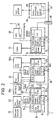
- Fig. 1 ein Block-Schaltbild einer Grundversion der erfindungsgemäßen Feuerleitanlage;
- Fig. 2 ein Block-Schaltbild einer zum Einsatz in einem Kampfpanzer vorgesehen Version und
- Fig. 3 ein Block-Schaltbild einer zum Einsatz in einem Schützenkampfwagen vorgesehenen Version.
- Fig. 1 is a block diagram of a basic version of the fire control system according to the invention;
- Fig. 2 is a block diagram of a version intended for use in a battle tank and
- Fig. 3 is a block diagram of a version intended for use in a rifle.
Die im folgenden zu beschreibende Feuerleitanlage in ihren verschiedenen Versionen zeichnet sich durch einfachen modulartigen Aufbau mit hohem Standardisierungsgrad aus. Sie erfordert geringen Prüfaufwand, bei leichter Fehlerlokalisierung und hohem Flexibilitätsgrad. Es können demzufolge problemlos weitere Geräte oder Sensoren angeschlossen werden und auch einzelne Geräte oder Sensoren gegen Nachfolgemodelle ausgetauscht werden. Wie die Ausführungsbeispiele zeigen werden, kann die erfindungsgemäße Feuerleitanlage ohne größere Änderungen in den verschiedensten Waffenträgern eingesetzt werden.The fire control system to be described in its various versions is characterized by a simple modular structure with a high degree of standardization. It requires little testing effort, easy error localization and a high degree of flexibility. As a result, additional devices or sensors can be easily connected, and individual devices or sensors can also be replaced with successor models. As the exemplary embodiments will show, the fire control system according to the invention can be used in a wide variety of weapon carriers without major changes.
Die Elektronik-Baugruppen der Feuerleitanlage sind an eine Bus-Leitung angeschlossen, wobei es sich jedoch als besonders günstig herausgestellt hat, nicht sämtliche Baugruppen einzeln an die Bus-Leitung anzuschließen, sondern mehrere, jeweils einem Bedienungsplatz zugeordnete Baugruppen in einem Einschubrahmen zusammenzufassen und über einen einzigen Bus-Terminal an die Bus-Leitung anzuschließen. Da jedem Bedienungsplatz ein Einschubrahmen mit weitgehend kompletter Elektronik zugeordnet ist, besteht die Möglichkeit für einen Inselbetrieb, falls die Kommunikation mit den anderen Einschubrahmen nicht mehr möglich ist, beispielsweise aufgrund eines Ausfalls der Bus-Leitung oder von Teilen der anderen Einschubrahmen. Schließlich ist die dezentrale Anordnung der Elektronik auch im Hinblick auf den zumeist beschränkten Einbauraum von Vorteil, da an den jeweiligen Bedienungsplätzen eher eine Platzreserve für kleinvolumige Baugruppen besteht als an zentraler Stelle für eine dementsprechend große Gesamtanlage.The electronic assemblies of the fire control system are connected to a bus line, although it has proven to be particularly advantageous not to connect all the assemblies individually to the bus line, but to combine several assemblies, each assigned to an operator station, in a slide-in frame and via one to connect the only bus terminal to the bus line. Since each operating station is assigned a slide-in frame with largely complete electronics, there is the possibility of island operation if communication with the other slide-in frames is no longer possible, for example due to a failure of the Bus line or parts of other slide-in frames. Finally, the decentralized arrangement of the electronics is also advantageous with regard to the mostly limited installation space, since there is more space available for small-volume modules at the respective operator stations than at a central location for a correspondingly large overall system.
In der Fig. 1 dargestellten Grundversion sind an drei Bedienungsplätzen jeweils ein Einschubrahmen 10,12,14 angeordnet, in die die dort jeweils benötigten elektronischen Baugruppen eingeschoben sind. Der Einschubrahmen 10 befindet sich in dem Bereich des Bedienungsplatzes des Richtschützens, der Einschubrahmen 12 im Bereich des Bedienungsplatzes des Kommandanten und der Einschubrahmen 14 an einen beliebigen weiteren Ort, beispielsweise in der Nähe des Funkgerätes. In dem mit FLA-Elektronik 1 (Feuerleitanlage) bezeichneten Einschubrahmen sind drei Baugruppen 16,18 und 20 eingeschoben. Die Baugruppe 16 ist mit HW-Stab. bezeichnet, was für Hauptwaffe-Stabilisierung steht. Die Baugruppe ist mit Schnittstellen u. Steuerung bezeichnet, was für Schnittstellen- und Steuerungs-Baugruppe steht, die Baugruppe 20 schließlich ist mit ZG-EL bezeichnet, was für Zielgerät-Elektronik steht. Die Schnittstellen- und Steuerungs-Baugruppe 18 übernimmt die Schnittstellen-Anpassung sämtlicher Baugruppen im Einschubrahmen 10 an die jeweils angeschlossenen Anschlußeinheiten. Im Falle des Richtschützen-Platzes sind dies eine Antriebseinheit 22 für Seite und Höhe der Hauptwaffe (mit HW Seite/Höhe in Fig. 1 bezeichnet), eine integrierte Bedien- und Anzeigeeinheit 24 (IBAS) sowie eine Wärmebildgerät-Einheit 26 (WBG). Letztere ist mit einem Zielgerät Richtschützen (ZGRisch 28) integriert, welches wiederum über eine starre mechanische Verbindung 30 mit der Hauptwaffe verbunden ist. Falls erforderlich, kann die Wärmebildgerät-Einheit 26 mit einer gesonderten Wärmebildgerät-Elektronikeinheit (WBGEL 32) verbunden sein, die in allgemeinen in die Wärmebildgerät-Einheit 26 integriert ist. Die Einheit 32 kann auch in den Rahmen 10 mitintegriert werden.In the basic version shown in FIG. 1, a slide-in
Über einen mit T bezeichneten Bus-Terminal 34 ist der Einschubrahmen 10 mit seinen Baugruppen 16,18,20 mit einer Bus-Leitung 36 verbunden (Anschlußleitung 38).The plug-in
Dementsprechend befindet sich am Bedienungsplatz des Fahrzeug-Kommandanten der Einschubrahmen, der mit FLA-Elektronik 2 bezeichnet ist. In diesen ist eine Schnittstellen- und Steuerungs-Baugruppe 40 eingeschoben sowie eine Zielgerät-Nachführungs-Baugruppe 42. Die Baugruppe 40 dient u.a. der Schnittstellen-Anpassung der Baugruppen des Einchubrahmens 12 mit den angeschlossenen Anschlußeinheiten. Es sind dies eine oder mehrere Feuerleitanlagen-Sensoreinheiten 44 (Vertikal-Sensor, Pulvertemperatur-Sensor, Querwind-Sensor oder dergl.), eine integrierte Bedien- und Anzeigeeinheit 46, ggf. eine entsprechende integrierte Bedien- und Anzeigeeinheit 48 für einen Ladeschützen (LS) sowie eine Zielgeräteinheit 50. Die Zielgerät-Nachführeinheit 42 sorgt dann für die Betätigung entsprechender Nachführantriebe in der Anschlußeinheit 50. Falls das Kommandanten-Zielgerät für sich lagestabilisiert ausgebildet sein soll, insbesondere in Form eines kreisel-stabilisierten Rundblick-Periskops, so ist anstelle der Zielgerät-Nachführungs-Baueinheit eine entsprechende Zielgerät-Stabilisierungs-Baueinheit 42a in den Einschubrahmen 12 einzuschieben, wie dies bei der Ausführungsform gemäß Fig. 2 der Fall ist. Im Falle einer in Fig. 3 angedeuteten mechanischen Kopplung zwischen der Zielgerät-Einheit 50 und der Hauptwaffe bzw. der Anschlußeinheit zur Einstellung von Seite/Höhe der Hauptwaffe, entfällt der entsprechende Einchub im Einschubrahmen 12.Accordingly, the slide-in frame, which is designated by FLA
In Systemen, in denen anstelle eines automatischen Laders ein Ladeschütze vorgesehen ist, kann an die Schnittstellen- und Steuerungs-Baugruppe 40 die integrierte Bedien- und Anzeigeeinheit des Ladeschützens 48 angeschlossen sein.In systems in which a charging contactor is provided instead of an automatic charger, the integrated operating and display unit of the charging
Die Schnittstellen- und Steuerungs-Baugruppe 40 dient neben ihrer Funktion der Schnittstellen-Anpassung zusätzlich zur Gesamtsteuerung des Systems als Zentraleinheit. Zusätzlich zu den ballistischen Berechnungen sorgt sie z.B. für die Betriebsarten-Auswahl, die es ermöglicht, daß wahlweise der Richtschütze oder der Kommandant, ggf. mit Prioritätsregelung zu gunsten des Kommandanten, die entsprechenden Feuerbefehle erteilt. Die Baugruppe 40 veranlaßt über den Bus 36 und die Baugruppen des Einschubrahmens 10, die in Verbindung mit der Anschlußeinheit 22 für die Einstellung von Höhe und Seite der Hauptwaffe stehen, daß die Hauptwaffe entsprechend geführt bzw. nachgeführt wird. Die Baugruppe 10 kann ferner zur Fehlerentdeckung und Fehlerlokalisierung des Gesamtsystems eingesetzt werden sowie zur Systemjustierung, falls beispielsweise mehrere Stabilisierungskreisel eingesetzt werden, deren Achsen zueinander prallel auszurichten sind.In addition to its function of adapting the interface, the interface and
Im Einschubrahmen 14 befindet sich wiederum eine Schnittstellen- und Steuerungs-Baugruppe 52 sowie ferner eine Hauptverteiler-Baugruppe 54. Die Baugruppe 52 sorgt wiederum für die Schnittstellen-Anpassung an die angeschlossenen Anschlußeinheiten, hier zu einer mit AEF bezeichneten Funk-Anpaß-Einheit 56 mit angeschlossener Steuer-Empfänger-Einheit 58 (Funkgerät für Datenfunk). In Fig. 1 wie auch in den anderen Figuren ist durch eine strichlierte Verbindungsleitung bzw. Umrißlinie des jeweiligen Blocks des Blockdiagramms angedeutet, daß diese Leitung bzw. der Block auch entfallen kann. Dementsprechend kann auch der Anschluß für den Datenfunk entfallen.In the slide-in
Die mit HV (Hauptverteiler) bezeichnete Baugruppe 54 dient der zentralen Stromversorgung sämtlicher Feuerleit-Baugruppen einschließlich der Geräteabsicherung. Auch können Leuchten und andere Geräte der Bord-Elektrik angeschlossen sein.The
In den Einbaurahmen 14 können bei Bedarf auch weitere Baugruppen für Sonderfunktionen eingesteckt werden, wie z.B. für eine Munitionsbunker-Türsteuerung.If required, further modules for special functions can also be plugged into the mounting
Um auch Daten über den Fahrzustand zu erhalten, kann die Bus-Leitung 36 über einen Schleifring 60 mit einer Anschluß-Bus-Leitung 64 innerhalb der Fahrzeugkarosserie bzw. Panzerwanne verbunden sein. An diese Bus-Leitung 64 kann wiederum innerhalb eines entsprechenden Einschubrahmens 66 eine für den Datenanschluß an das Fahrgestell sorgende Baugruppe 68 angeschlossen sein. Auf diese Weise kann von der für die Gesamtsteuerung zuständigen Schnittstellen- und Steuerungs-Baugruppe 40 auch eine direkte Prüfung der Bord-Elektrik vorgenommen werden.In order to also receive data about the driving state, the
In Fig. 2 ist eine zum Einsatz in einem Kampfpanzer vorgesehen Version der Feuerleitanlage dargestellt. Im Unterschied zur einfachen Grundversion gemäß Fig. 1 sind hier sowohl die Zielgerät-Einheit 28a des Richtschützen als auch die Zielgeräteinheit 50a des Kommandanten jeweils mit voneinander unabhängigen Stabilisierungseinrichtungen ausgerüstet, die wiederum über eine entsprechende Zielgerät-Stabilisierungs-Baugruppe 20a bzw. 42a im Einschubrahmen 10 bzw. 12 zur entsprechenden Lagestabilisierung des jeweiligen Zielgeräts auch bei voller Fahrt verbunden. Anzumerken ist ferner, daß ein Hilfs-Zielfernrohr 70 mit der Hauptwaffe starr verbunden sein kann. Ferner unterschiedlich zur Fig. 1 ist, daß nunmehr ein automatischer Lader 72 vorgesehen ist, welcher mit einer entsprechenden mit "Auto-Lader" bezeichneten Baugruppe 74 im Einschubrahmen 14 über die Schnittstellen- und Steuerungs-Baugruppe 52 verbunden ist.2 shows a version of the fire control system intended for use in a battle tank. In contrast to the simple basic version according to FIG. 1, both the aiming
Die unterste Ausstattungsvariante gemäß Fig. 3 ist eine Feuerleitanlage für einen Schützenkampfwagen. Dabei ist vorausgesetzt, daß für das Waffensystem mindestens eine primär stabilisierte Maschinenkanone vorgesehen ist. Für Kampfwagen mit noch einfacherer Bewaffnung ist eine Feuerleitanlage nicht mehr erforderlich.3 is a fire control system for a rifle combat vehicle. It is assumed that at least one primarily stabilized machine gun is provided for the weapon system. A fire control system is no longer required for combat vehicles with even simpler armament.
Bei dieser Version sind die Zielgeräte-Einheiten 28 und 50 für den Richtschützen und den Kommandanten mechanisch mit der Hauptwaffe gekoppelt. Da bei derartigen Fahrzeugen die Waffentürme geringe räumliche Abmessungen haben und somit der Einbauraum weiter beschränkt ist, konzentrieren sich die einzuschiebenden Elektronik-Baugruppen auf den Einschubrahmen 10 (FLA-Elektronik 1) sowie den Einschubrahmen 14 (FLA-Elektronik 3).In this version, the aiming
Im Einschubrahmen 10 befindet sich wiederum die Hauptwaffen-Stabilisierungsbaugruppe 16, die Schnittstellen- und Steuerungs-Baugruppe 18 sowie in diesem Falle eine Wärmebild-Gerätbaugruppe 32a, die die gesonderte Einheit 32 in den Figuren 1 und 2 ersetzt. Bei Bedarf, z.B. dann, wenn eine komplette Funktionsredundanz aus Sicherheitsgründen gefordert wird, kann der bei der Normalausführung entfallende Einschubrahmen 12 vorgesehen sein. Während in der Normalversion die für den Kommandanten vorgesehene integrierte Bedien- und Anzeigeeinheit 46 an den Einschubrahmen 10 angeschlossen ist, kann diese alternativ auch an den Einschubrahmen 12 angeschlossen sein.In the slide-in
Die übrigen, nicht eigens aufgeführten Komponenten der Anordnungen in den Figuren 2 und 3 entsprechen den in Fig. 1 und sind dementsprechend in den Figuren 2 und 3 mit gleichen Bezugsziffern versehen.The other, not specifically listed components of the arrangements in FIGS. 2 and 3 correspond to those in FIG. 1 and are accordingly provided with the same reference numbers in FIGS. 2 and 3.
Die beschriebenen Feuerleitanlagen haben eine hohe Ausfallsicherheit. Fällt beispielsweise die die Gesamtsteuerung der Anlage durchführende Schnittstellen- und Steuerungs-Baugruppe 40 aus, so wird deren Funktion sofort übernommen von der Schnittstellen- und Steuerungs-Baugruppe 18. Hierbei wird von der Baugruppe 18 u.a. auch die volle Daten-Bus-Steuerung übernommen, so daß die Steuerung der FLA-Elektronik 3 mit dem automatischen Lader nach wie vor durch den Richtschützen ohne Einschränkung möglich ist. Nur der Kommandant ist nicht mehr in der Lage, die Hauptwaffe selbst zu führen. Schließlich kann bei Ausfall der Bus-Leitung 36 FLA-Elektronik 1 für sich noch voll funktionsfähig sein, wenn auch in diesem Falle der automatische Lader manuell ausgelöst werden müßte.The fire control systems described have a high level of reliability. If, for example, the overall control of the system and the interface and
Einander in der Funktion entsprechende Baugruppen sind hardwaremäßig identisch aufgebaut, so z.B. sämtliche Schnittstellen- und Steuerungs-Baugruppen 18,40,52 und sämtliche der Stabilisierung dienenden Baugruppen 16,20a und 42a. Die jeweils erforderlichen Anpassungsparameter-Datensätze werden den Baugruppen in bereits vorstehend beschriebener Art und Weise zugeführt.Hardware-equivalent modules have the same hardware structure, e.g. all interface and
Die Verbindung der Gruppen der Einschubrahmen 10,12,14 mit dem Bus 36 erfolgt jeweils über ein den einzigen Bus-Terminal 80, der von jeweiligen Schnittstellen- und Steuerungs-Baugruppe angesteuert wird. Ferner sei angemerkt, daß an den Bus 36 ohne weiteres auch weitere Einheiten angeschlossen werden können, wie z.B. weitere Sensoren für ballistische Parameter oder dergl.The groups of plug-in
Die Erfindung, wie vorgehend beschrieben kann wie folgt zusammengefaßt werden:The invention as described above can be summarized as follows:
Eine Feuerleitanlage mit wenigstens zwei Bedienungsplätzen umfaßt pro Bedienungsplatz einen Einschubrahmen mit elektronischen Baugruppen, pro Rahmen wenigstens eine Funktions-Baugruppe sowie eine Schnittstellen- und Steuerungs-Baugruppe und eine Bus-Leitung, wobei wenigstens ein Teil der Funktions-Baugruppen von im wesentlichen identischen Standard-Baugruppen gebildet sind, und wobei die Gesamtsteuerung der Feuerleitanlage von einer vorbestimmten ersten Schnittstellen- und Steuerungs-Baugruppe und bei deren Ausfall von einer vorbestimmten zweiten Schnittstellen- und Steuerungs-Baugruppe durchgeführt und wobei schließlich bei Ausfall der Bus-Leitung die Schnittstellen- und Steuerungs-Baugruppe des der Hauptwaffe zugeordneten Einschubrahmens die selbsttätige Steuerung der Baugruppen dieses Einschubrahmens durchführt.A fire control system with at least two control stations comprises a slide-in frame with electronic modules per control station, at least one function module as well as an interface and control module and a bus line per frame, at least some of the function modules being of essentially identical standard Modules are formed, and wherein the overall control of the fire control system is carried out by a predetermined first interface and control module and, if it fails, by a predetermined second interface and control module, and finally, if the bus line fails, the interface and control Assembly of the slide-in frame assigned to the main weapon carries out the automatic control of the assemblies of this slide-in frame.
Claims (9)
- pro Bedienungsplatz einen Einschubrahmen (10,12,14) mit elektronischen Baugrauppen,
- pro Rahmen wenigstens eine Funktions-Baugruppe, insbesondere Stabilisierungs-Baugruppe (16,20a,42a) für die Hauptwaffe oder ein Zielgerät oder Hauptversorgungs-Baugruppe (54),
- pro Rahmen wenigstens eine Schnittstellen- und Steuerungs-Baugruppe (34,40,52),
- eine Bus-Leitung (36), an die die Schnittstellen und Steuerungs-Baugruppen sämtlicher Rahmen angeschlossen sind,
wobei wenigstens ein Teil der Funktionsbaugruppen von im wesentlichen identischen Standard-Baugruppen gebildet sind,
wobei vorzugsweise die Gesamtsteuerung der Feuerleitanlage von einer vorbestimmten ersten Schnittstellen- und Steuerungsbaugruppe (40) und bei deren Ausfall von einer vorbestimmten zweiten Schnittstellen- und Steuerungs-Baugruppe (18) durchgeführt wird, und
wobei vorzugsweise ferner bei Ausfall der Bus-Leitung (36) die Schnittstellen- und Steuerungs-Baugruppe (18) des der Hauptwaffe (22) zugeordneten Einschubrahmens (10) die selbsttätige Steuerung der Baugruppen (16,20) dieses Einschubrahmens (10) durchführt.1. Fire control system with at least two operator stations, comprehensive
- one slide-in frame (10, 12, 14) with electronic assemblies per control station,
at least one functional assembly, in particular a stabilization assembly (16, 20a, 42a) for the main weapon or a target device or main supply assembly (54),
- at least one interface and control module (34, 40, 52) per frame,
a bus line (36) to which the interfaces and control modules of all frames are connected,
at least some of the functional assemblies being formed by essentially identical standard assemblies,
preferably the overall control of the fire control system from a predetermined first interface and control module (40) and, if it fails, is carried out by a predetermined second interface and control module (18), and
Preferably, if the bus line (36) fails, the interface and control module (18) of the slide-in frame (10) assigned to the main weapon (22) carries out the automatic control of the modules (16, 20) of this slide-in frame (10).
Applications Claiming Priority (2)
| Application Number | Priority Date | Filing Date | Title |
|---|---|---|---|
| DE19883802894 DE3802894A1 (en) | 1988-02-01 | 1988-02-01 | FIRE CONTROL SYSTEM |
| DE3802894 | 1988-02-01 |
Publications (2)
| Publication Number | Publication Date |
|---|---|
| EP0327029A2 true EP0327029A2 (en) | 1989-08-09 |
| EP0327029A3 EP0327029A3 (en) | 1990-12-27 |
Family
ID=6346382
Family Applications (1)
| Application Number | Title | Priority Date | Filing Date |
|---|---|---|---|
| EP19890101648 Withdrawn EP0327029A3 (en) | 1988-02-01 | 1989-01-31 | Fire control device |
Country Status (2)
| Country | Link |
|---|---|
| EP (1) | EP0327029A3 (en) |
| DE (1) | DE3802894A1 (en) |
Cited By (4)
| Publication number | Priority date | Publication date | Assignee | Title |
|---|---|---|---|---|
| EP0405732A2 (en) * | 1989-06-07 | 1991-01-02 | The Marconi Company Limited | Digital signal multiprocessor |
| EP0852326A1 (en) * | 1996-12-09 | 1998-07-08 | Oerlikon-Contraves AG | Weapon battery, specially for anti-aircraft fire units |
| FR2873221A1 (en) * | 2004-07-16 | 2006-01-20 | Dcn Sa | Strategic information processing and managing system for combat platform e.g. submarine, has structures stacking layers of interfaceable software modules and selected in corresponding library of software modules |
| WO2006126966A2 (en) * | 2005-05-25 | 2006-11-30 | Bae Systems Bofors Ab | System and process for displaying a target |
Families Citing this family (1)
| Publication number | Priority date | Publication date | Assignee | Title |
|---|---|---|---|---|
| DE19716198C2 (en) * | 1997-04-18 | 1999-11-04 | Rheinmetall W & M Gmbh | Weapon system |
Citations (5)
| Publication number | Priority date | Publication date | Assignee | Title |
|---|---|---|---|---|
| GB2136097A (en) * | 1979-03-30 | 1984-09-12 | Siemens Ag | Target-tracking Interception Control Systems |
| US4634110A (en) * | 1983-07-28 | 1987-01-06 | Harris Corporation | Fault detection and redundancy management system |
| US4639856A (en) * | 1983-11-04 | 1987-01-27 | International Business Machines Corporation | Dual stream processor apparatus |
| FR2597226A1 (en) * | 1986-04-09 | 1987-10-16 | Messerschmitt Boelkow Blohm | Guidance computer for a launch installation |
| EP0249679A2 (en) * | 1986-04-18 | 1987-12-23 | MaK System Gesellschaft mbH | Fire guiding system for a weapon equipment of an armoured vehicle |
-
1988
- 1988-02-01 DE DE19883802894 patent/DE3802894A1/en not_active Withdrawn
-
1989
- 1989-01-31 EP EP19890101648 patent/EP0327029A3/en not_active Withdrawn
Patent Citations (5)
| Publication number | Priority date | Publication date | Assignee | Title |
|---|---|---|---|---|
| GB2136097A (en) * | 1979-03-30 | 1984-09-12 | Siemens Ag | Target-tracking Interception Control Systems |
| US4634110A (en) * | 1983-07-28 | 1987-01-06 | Harris Corporation | Fault detection and redundancy management system |
| US4639856A (en) * | 1983-11-04 | 1987-01-27 | International Business Machines Corporation | Dual stream processor apparatus |
| FR2597226A1 (en) * | 1986-04-09 | 1987-10-16 | Messerschmitt Boelkow Blohm | Guidance computer for a launch installation |
| EP0249679A2 (en) * | 1986-04-18 | 1987-12-23 | MaK System Gesellschaft mbH | Fire guiding system for a weapon equipment of an armoured vehicle |
Non-Patent Citations (1)
| Title |
|---|
| PROCEEDINGS OF THE IEEE, NAECON, 1986, Band 1, Seiten 119-124; G. ELENGICAL et al.: "Capability assessment in airborne platforms" * |
Cited By (9)
| Publication number | Priority date | Publication date | Assignee | Title |
|---|---|---|---|---|
| EP0405732A2 (en) * | 1989-06-07 | 1991-01-02 | The Marconi Company Limited | Digital signal multiprocessor |
| EP0405732A3 (en) * | 1989-06-07 | 1993-02-03 | The Marconi Company Limited | Digital signal multiprocessor |
| EP0852326A1 (en) * | 1996-12-09 | 1998-07-08 | Oerlikon-Contraves AG | Weapon battery, specially for anti-aircraft fire units |
| FR2873221A1 (en) * | 2004-07-16 | 2006-01-20 | Dcn Sa | Strategic information processing and managing system for combat platform e.g. submarine, has structures stacking layers of interfaceable software modules and selected in corresponding library of software modules |
| WO2006126966A2 (en) * | 2005-05-25 | 2006-11-30 | Bae Systems Bofors Ab | System and process for displaying a target |
| WO2006126966A3 (en) * | 2005-05-25 | 2007-09-20 | Bae Systems Bofors Ab | System and process for displaying a target |
| GB2440882A (en) * | 2005-05-25 | 2008-02-13 | Bae Systems Bofors Ab | System and process for displaying a target |
| GB2440882B (en) * | 2005-05-25 | 2008-11-19 | Bae Systems Bofors Ab | System and process for displaying a target |
| US8624781B2 (en) | 2005-05-25 | 2014-01-07 | Bae Systems Bofors Ab | System and process for displaying a target |
Also Published As
| Publication number | Publication date |
|---|---|
| EP0327029A3 (en) | 1990-12-27 |
| DE3802894A1 (en) | 1989-08-10 |
Similar Documents
| Publication | Publication Date | Title |
|---|---|---|
| EP1495280B1 (en) | Combat vehicle, especially an armoured vehicle and tank, with a panoramic sighting device | |
| EP1061323B2 (en) | Armoured vehicle for the transport of soldiers | |
| EP1752376A2 (en) | Aircraft, in particular unmanned aircraft, with at least one weapons bay | |
| EP1371931B1 (en) | Method and device for determining an angular error and use thereof | |
| DE3122384A1 (en) | DEVICE WITH SEVERAL TRAINING PLACES FOR TRAINING RIFLE SAWS AND / OR COMMANDERS OF FIGHTING VEHICLES | |
| DE4336207A1 (en) | Interface arrangement for data transmission between the carrier aircraft and the missile | |
| EP0327029A2 (en) | Fire control device | |
| EP1508765B1 (en) | Modular weapon station, in particular for fitting on a combat vehicle | |
| DE3023516A1 (en) | Monitor system for armoured fighting vehicles - has TV cameras coupled optically to gun sights transmitting telemetry to command post | |
| EP0097231B1 (en) | Surveillance device for a fighting vehicle, particularly an armoured vehicle | |
| DE2912587C1 (en) | Fire control device, in particular for a mobile anti-aircraft system | |
| DE3327384A1 (en) | VISOR SYSTEM FOR A STEERING AIRCRAFT | |
| DE19532743C2 (en) | Device for aiming a weapon of an armed vehicle | |
| CH656700A5 (en) | DEVICE FOR MONITORING A COMBAT VEHICLE, ESPECIALLY A COMBAT TANK IN TRAINING USE FROM A CONTROL CENTER. | |
| EP1549899B1 (en) | Device for protecting objects against ammunition in the form of guided missiles | |
| DE3613097C2 (en) | ||
| DE3023553C2 (en) | ||
| DE1258302B (en) | Sighting device | |
| DE102022106062A1 (en) | Method and emergency control unit for operating an emergency control system for a gun device, gun device and vehicle | |
| DE2740655A1 (en) | AUTOMATIC SEARCH HEAD INSTRUCTION | |
| DE10133147B4 (en) | Armored transport vehicle | |
| DE112020000185T5 (en) | SINGLE PLATE TARGET CONTROL MECHANISM WITH INDEPENDENT MOVEMENT AND LOCKABILITY | |
| DE102004003055A1 (en) | Arrangement of a first and at least one other vehicle in a loosely coupled non-track-bound train | |
| DE3333425C2 (en) | ||
| WO2024022748A1 (en) | Effektor data connector for data connection of an effector to a firing platform |
Legal Events
| Date | Code | Title | Description |
|---|---|---|---|
| PUAI | Public reference made under article 153(3) epc to a published international application that has entered the european phase |
Free format text: ORIGINAL CODE: 0009012 |
|
| AK | Designated contracting states |
Kind code of ref document: A2 Designated state(s): AT BE CH DE ES FR GB GR IT LI NL SE |
|
| PUAL | Search report despatched |
Free format text: ORIGINAL CODE: 0009013 |
|
| AK | Designated contracting states |
Kind code of ref document: A3 Designated state(s): AT BE CH DE ES FR GB GR IT LI NL SE |
|
| 17P | Request for examination filed |
Effective date: 19910416 |
|
| 17Q | First examination report despatched |
Effective date: 19921027 |
|
| STAA | Information on the status of an ep patent application or granted ep patent |
Free format text: STATUS: THE APPLICATION IS DEEMED TO BE WITHDRAWN |
|
| 18D | Application deemed to be withdrawn |
Effective date: 19930309 |