EP0326428A2 - Discharge recovery method for an ink jet recording head, recording head adopting the same method and ink jet recording apparatus adopting the same method - Google Patents
Discharge recovery method for an ink jet recording head, recording head adopting the same method and ink jet recording apparatus adopting the same method Download PDFInfo
- Publication number
- EP0326428A2 EP0326428A2 EP89300848A EP89300848A EP0326428A2 EP 0326428 A2 EP0326428 A2 EP 0326428A2 EP 89300848 A EP89300848 A EP 89300848A EP 89300848 A EP89300848 A EP 89300848A EP 0326428 A2 EP0326428 A2 EP 0326428A2
- Authority
- EP
- European Patent Office
- Prior art keywords
- ink
- discharge
- recording head
- ink jet
- jet recording
- Prior art date
- Legal status (The legal status is an assumption and is not a legal conclusion. Google has not performed a legal analysis and makes no representation as to the accuracy of the status listed.)
- Granted
Links
Images


Classifications
-
- B—PERFORMING OPERATIONS; TRANSPORTING
- B41—PRINTING; LINING MACHINES; TYPEWRITERS; STAMPS
- B41J—TYPEWRITERS; SELECTIVE PRINTING MECHANISMS, i.e. MECHANISMS PRINTING OTHERWISE THAN FROM A FORME; CORRECTION OF TYPOGRAPHICAL ERRORS
- B41J2/00—Typewriters or selective printing mechanisms characterised by the printing or marking process for which they are designed
- B41J2/005—Typewriters or selective printing mechanisms characterised by the printing or marking process for which they are designed characterised by bringing liquid or particles selectively into contact with a printing material
- B41J2/01—Ink jet
- B41J2/17—Ink jet characterised by ink handling
- B41J2/18—Ink recirculation systems
-
- B—PERFORMING OPERATIONS; TRANSPORTING
- B41—PRINTING; LINING MACHINES; TYPEWRITERS; STAMPS
- B41J—TYPEWRITERS; SELECTIVE PRINTING MECHANISMS, i.e. MECHANISMS PRINTING OTHERWISE THAN FROM A FORME; CORRECTION OF TYPOGRAPHICAL ERRORS
- B41J2/00—Typewriters or selective printing mechanisms characterised by the printing or marking process for which they are designed
- B41J2/005—Typewriters or selective printing mechanisms characterised by the printing or marking process for which they are designed characterised by bringing liquid or particles selectively into contact with a printing material
- B41J2/01—Ink jet
- B41J2/135—Nozzles
- B41J2/165—Preventing or detecting of nozzle clogging, e.g. cleaning, capping or moistening for nozzles
- B41J2/16517—Cleaning of print head nozzles
- B41J2/1652—Cleaning of print head nozzles by driving a fluid through the nozzles to the outside thereof, e.g. by applying pressure to the inside or vacuum at the outside of the print head
- B41J2/16526—Cleaning of print head nozzles by driving a fluid through the nozzles to the outside thereof, e.g. by applying pressure to the inside or vacuum at the outside of the print head by applying pressure only
Definitions
- This invention relates to a discharge recovery method for an ink jet recording head provided with discharge recovery means for recovery from unsatisfactory discharge of ink from the discharge openings of the ink jet recording head to thereby accomplish discharge recovery.
- An ink jet recording apparatus is such that ink is supplied into a recording head, a drive element provided correspondingly to at least one ink discharge opening formed in the front surface of the recording head is driven on the basis of a recording data signal to thereby cause the ink to be discharge through the ink discharge opening and form a flying liquid droplet toward a recording medium and such liquid droplet is caused to adhere to the recording medium to thereby accomplish recording.
- the drive element used for recording is used also as the drive element for pre-discharge, and there have been technical tasks left to be solved in the points which will be described later.
- the drive element is used for the two purposes, and this is effective in the prevention of clogging or unsatisfactory discharge, but when unsatisfactory discharge has already occurred as may occur when recording is again effected from a long time of unused state, the effect of releasing it is not high.
- Figure 1 is a schematic cross-sectional view showing an ink jet recording head to which the recovery method of the present invention is applied.
- the reference numeral 1 designates a recording head carrying thereon various members which will be described later and discharging ink to recording paper or the like to thereby form ink droplets
- the reference numeral 2 denotes a plurality of liquid paths provided in the fore end portion of the recording head 1
- the reference numeral 3 designates heaters for recording as electro-thermal converting elements disposed at the bottom correspondingly to the liquid paths 2 and supplied with electric power during recording to generate heat energy utilized for ink discharge
- the reference numeral 4 denotes a common liquid chamber communicating with the rear ends of the liquid paths 2 and supplying ink to them
- the reference numeral 5 designates a heater for applying pressure disposed at the bottom of the common liquid chamber 4 as shown in Figure 2
- the reference numeral 6 denotes a check valve provided in an ink supply portion 7 for the common liquid chamber 4
- the reference numeral 8 designates a flexible cable containing therein a driving signal line connected to each of the heaters 3 for recording
- the reference numeral 9 de
- the present invention can be suitably applied to an ink jet recording apparatus of the type in which a recording head and an ink tank for containing therein ink to be supplied to the recording head are integrally and removably carried relative to a carriage.
- a recording head and an ink tank for containing therein ink to be supplied to the recording head are integrally and removably carried relative to a carriage.
- the ink tank may be removably mounted.
- the check valve 6 is made of plastic film, metal foil or a shape memorizing alloy on the boundary surface between the ink supply portion 7 and the common liquid chamber 4, and prevents the ink from flowing from the common liquid chamber 4 back to the ink supply portion 7 side when bubbles are made in the common liquid chamber 4 by the heater 5 for applying pressure.
- plastic film, metal foil or the like is used for the check valve 6, if the plate thickness is of the order of 50 ⁇ m, there will be obtained a check valve excellent in the responsiveness to the fluctuation of applied pressure.
- the ink supplied from the ink supply portion 7 fills the common liquid chamber 4 and the liquid paths 2.
- the heater 5 for applying pressure is not supplied with electric power on the basis of a signal generated by means for generating a recording signal, but only the heaters 3 for recording are supplied with electric power in conformity with the recording signal.
- bubbles are created by film boiling, and with these bubbles as the pressure force, ink droplets fly out from the fore ends of the liquid paths 2 toward recording paper.
- New ink is supplied into the liquid paths in which the bubbles have been produced, due to negative pressure created in the liquid paths with the flight of the ink droplets, and an amount of ink corresponding to the decrement is supplied form the ink supply portion 7 to the common liquid chamber 4 through the check valve 6.
- the check valve is not restricted to the construction of Figure 1, but may also be of a structure as shown in Figure 4 wherein the fore end portion thereof is formed by an elastic member adapted to be closed by ink pressure and a filter 11 for removing any dust contained in the ink is provided in the ink paths. By doing so, any dust which may cause clogging of the discharge openings to be common liquid chamber 4 and of the liquid paths can be removed.
- the check valve can also be designed as other construction than a valve mechanism, as shown in Figure 5. That is, a heater 12 for checking is provided on the bottom surface of the common liquid chamber 4 which is near the outlet of the ink supply portion 7.
- the reference numeral 9 designates a lead connected to the heater 5 for applying pressure and the heater 12 for checking.
- electric power is supplied to the heater 12 for checking for the order of 10 ⁇ sec. to increase the heater temperature to several hundred degrees, and thereby film-boils the ink on the upper surface of the heater 5 for applying pressure.
- a bubble 13 is created as shown in Figure 6 and the outlet of the ink supply portion 7 can be closed. This bubble 13 disappears in 20 - 30 ⁇ sec. by cutting of the supply of electric power to the heater 12 for checking, and the subsequent supply of the ink to the common liquid chamber 4 can be accomplished without any hindrance.
- a slit opening 16 may be provided at the fore end of the ink supply portion 7, as shown in Figure 7, and may be used instead of the heater 12 for checking having a length greater than the widthwise dimension of the slit opening.
- the recovery mode is automatically assumed after the switch operation of the recording apparatus during unsatisfactory discharge or a predetermined amount of discharging operation, whereby the heater 5 for applying pressure is heated and the check valve 6 is operated by a bubble resulting therefrom and the air, the remaining bubble, etc. in the liquid paths are removed as shown in Figure 2.
- the heater 5 for applying pressure is turned off, the created bubble begins to disappear and negative pressure begins to be created in the common liquid chamber 4.
- the check valve 6 is opened and also, the retraction of the meniscus of the liquid paths 2 is prevented by the meniscus holding force of about 50 ⁇ m of the discharge openings and the low flow path resistance of the ink supply portion having a large diameter relative to the inner diameter of the discharge openings of the liquid paths.
- the heater 12 for checking is supplied with electric power by means for generating a checking signal and a bubble 13 is created as shown in Figure 6, whereby the ink supply to the common liquid chamber 4 is cut off.
- the heater 5 for applying pressure is then supplied with electric power to cause a bubble to be created in the common liquid chamber 4 as shown in Figure 3, and the ink is forced into the respective liquid paths 2.
- the heater 12 for checking is turned off and the ink supply portion 7 is connected to the common liquid chamber 4.
- the heater 5 for applying pressure is then turned off, the bubble thereby disappears and negative pressure is created and thus, the ink flows from the ink supply portion 7 into the common liquid chamber 4.
- pressure is kept uniform with the meniscus of the discharge openings maintained.
- the heater 12 for checking is supplied with electric power and a bubble 13 is created as shown in Figure 6, whereby the ink supply to the common liquid chamber 4 is cut off.
- the heater 5 for applying pressure is then supplied with electric power to thereby cause a bubble to be created in the common liquid chamber 4 as shown in Figure 3, and the ink is forced into the respective liquid paths 2.
- the heater 12 for checking is turned off and the ink supply portion 7 is connected to the common liquid chamber 4.
- the heater 5 for applying pressure is then turned off, the bubble thereby disappears and negative pressure is created, and the ink flows from the ink supply portion 7 into the common liquid chamber 4.
- pressure is kept uniform with the meniscus of the discharge openings of the liquid paths maintained.
- discharge recovery can be achieved by controlling only the heater in the common liquid chamber, and the amount of ink discharged from the discharge openings can be made very small. Also, since the present invention does not depend on any mechanical construction, the recovery time depends only on the refill of the ink and the operating time can be made very short, and can be kept within such a degree of time that the use of the recovery mode cannot be recognized by the user.
- the control of the supply of electric power can be accomplished not only by a method using a variation in the pulse width, but also by a reduction in the on-duty or a reduction in the voltage applied to the heater resistor.
- the heaters for recording are designed such that as the condition of the input pulse for forming an ink droplet, they are controlled so that as shown in U.S. Patent No. 4,345,262 issued to Shirato, the input cycle is at least three times a pulse width of 0.1 ⁇ sec. - 500 ⁇ sec., but according to the present embodiment, by using the heater for applying pressure discretely from the heaters for recording, it becomes possible to apply a signal which is not subjected to said limitation, and this leads to the merit that the range of the selection of the driving condition of the heater for applying pressure becomes wider.
- FIG 11 schematically shows the construction of a control system for controlling the supply of electric power to the heaters.
- the output of a control unit 16 is connected to the heater 5 for applying pressure, and this control unit 16 uses the output signal of a temperature detecting thermistor (Th) 18 provided in the head 1 as a feedback signal and controls the power supply time by the set time of a timer 17.
- the reference numeral 19 designates an ink supply source.
- Figure 12 shows the position of the head when discharge recovery is effected.
- a platen 20 for conveying recording paper 21 as a recording medium in conformity with the printing situation is rotatably supported on the body, and a guide shaft 22 is fixedly disposed parallel to the front portion of the platen 20 and in a horizontal direction.
- a carriage 23 is slidably engaged with the guide shaft 22, and is reciprocally moved on the guide shaft 22 in conformity with the printing condition, with a carriage motor, not shown, as a drive source.
- the recording head 1 is mounted on the carriage 23, and discharge recovery is executed when the recording head 1 is in its home position (H.P.).
- the reference numeral 24 designates a wiping blade having a plate-like elastic member for wiping away the ink adhering to the surface of the head after the completion of the discharge recovery when the carriage 23 is moved.
- the discharge recovery operation according to the present invention is performed within a very short time and therefore, the time required for the discharge recovery operation, including the time required for returning the carriage 23 to its home position, may be less than one second. Accordingly, the user will not be caused to feel actually the interruption of recording.
- Figure 13 is a flow chart in a case where the discharge recovery according to the present invention is automatically effected.
- step 31 After the power source switch is closed, the recording operation is performed (step 31), and in that process, whether a period during which the discharge recovery operation is necessary has come is judged (step 32).
- step 33 the carriage 23 is returned to its home position (step 33), and electric power is supplied to the heater 5 (or depending on the timing of Figure 10, to the heater 12 and the heater 5) and the discharge recovery operation by the bubble created thereby is performed (step 34).
- step 34 the carriage 23 is moved rightwardly as viewed in Figure 12, and in that process, the surface of the head (which is near the discharge openings) is cleaned by the blade 24 (step 35). After this treatment, return is made to the step 31, where the recording operation is resumed.
- the judgment condition has been "printing for a predetermined time”
- it may also be “stoppage of printing for a predetermined time”.
- the "recording operation" of the step 31 after the closing of the power source switch has been made reliable, but a recovery operation of the same content as the step 34 may be inserted before the step 31. If this is done, even if the apparatus remains unused for a long time before the closing of the power source switch, unsatisfactory discharge will not be caused in the recording at the step 31.
- step 32 may be the condition for the completion of printing of a predetermined number of sheets (or a predetermined number of pages), instead of the process content of Figure 13.
- step 36 may be provided with a view to remove any remaining air created by the heaters 3 for recording with the rise of the head temperature caused by the continuous use of the nozzle.
- the pre-discharge operation is effected a plurality of times as one recovery operation, and in order to make the amount of heat energy produced by the heater for applying pressure in one pre-discharge operation greater than the amount of heat energy produced by the heaters for recording in one discharge operation, where the materials and the film thicknesses of said heaters are the same, design is made such that the following relation is established when the area of the heaters k for recording is a k and the area of the heater for applying pressure is b: (N is the number of heaters for recording.) and more preferably, whereby-the frequency of application of the pre-discharge signal could be reduced.
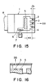
- the recording head schematically shown in Figure 15 is a head of the type in which ink is discharged in a direction substantially parallel to the surface of the heat generating portion of the heaters for recording (the direction of arrow AA).
- the length of said heat generating portion in the direction of discharge (the arrow AA) is l k and the spacing between the heaters 3 for recording and the heater 5 for applying pressure is m k , it is desirable to determine the positions of these heaters so as to satisfy the relation that m k ⁇ l k or m k ⁇ ⁇ a k .
- a recording head to which the present invention is applicable in a head of the type which discharges ink in a direction substantially perpendicular to the surface of the heat generating portion of the heaters for recording (the direction of arrow BB in Figure 16), it is rarely the case that the stagnation of bubbles occurs at a position greatly spaced apart from the surface of the heat generating portion and therefore, the above-described position is not restrictive, but it is still preferable to provide a heater for applying pressure at a similar position.
- the present invention by providing the heater for applying pressure discretely from the heaters for recording, unsatisfactory discharge which could not be released by the conventional pre-discharge operation can be released to thereby accomplish a good discharge recovery operation without shortening the life of the heaters for recording.
- the heater for applying pressure can be made into desired structure and moreover can be disposed more adjacent to the heaters for recording and therefore, it becomes possible to produce a pressure force at a location whereat bubbles or foreign materials are ready to stagnate, and the efficiency of discharge recovery can be remarkably improved without discharging a great deal of ink.
Abstract
Description
- This invention relates to a discharge recovery method for an ink jet recording head provided with discharge recovery means for recovery from unsatisfactory discharge of ink from the discharge openings of the ink jet recording head to thereby accomplish discharge recovery.
- An ink jet recording apparatus is such that ink is supplied into a recording head, a drive element provided correspondingly to at least one ink discharge opening formed in the front surface of the recording head is driven on the basis of a recording data signal to thereby cause the ink to be discharge through the ink discharge opening and form a flying liquid droplet toward a recording medium and such liquid droplet is caused to adhere to the recording medium to thereby accomplish recording.
- In the recording head of the ink jet recording apparatus of this type, unsatisfactory discharge is caused by the entry of the air into a liquid path communicating with the ink discharge opening or the adherence of paper dregs or viscosity-increased ink to the liquid path. In order to eliminate such unsatisfacotry discharge and achieve the stability of discharge, as shown, for example, in U.S. Patent No. 4,600,931 issued to Terasawa and U.S. Patent No. 4,123,761 issued to Kimura, a gear pump or the like has been provided in an ink supply path communicating with the recording head and supplying ink to thereby forcibly pressurize the ink and cause the air and foreign materials in the liquid path to be discharged, or a pump mechanism or the like for sucking air and foreign materials from the discharge opening by negative pressure and causing them to be discharged has been provided.
- However, in the conventional recovery method for an ink jet recording head, it is necessary to discharge a great deal of ink to eliminate the air slightly stagnating in the liquid path or the viscosity-increased ink in the discharge opening and the liquid path. Also, much time is required for operating these drive systems (the pump, etc.) and as a result, it is necessary to stop recording temporarily, and it could not be said that efficient use was made.
- Also, discretely from the above-described construction, a construction in which a drive element such as a piezoelectric element for discharge is driven during non-recording to thereby effect pre-discharge, as described, for example, in U.S. Patent No. 3,925,788 issued to Kashio, U.S. Patent No. 3,925,789 issued to Kashio, U.S. Patent No. 4,183,030 issued to Kaieda et al., and U.S. Patent No. 4,176,363 issued to Kasahara has been proposed.
- However, in the above-described construction wherein pre-discharge is effected, the drive element used for recording is used also as the drive element for pre-discharge, and there have been technical tasks left to be solved in the points which will be described later.
- In the pre-discharge of the above-described construction, the drive element is used for the two purposes, and this is effective in the prevention of clogging or unsatisfactory discharge, but when unsatisfactory discharge has already occurred as may occur when recording is again effected from a long time of unused state, the effect of releasing it is not high.
- Also, a construction in which the pre-discharge of the above-described construction is effected with the driving conditions or the like changed is shown, for example, in U.S. Patent No. 4,466,005 issued to Yoshimura. However, in the construction described above in detail, there have been left the technical tasks that in the sence that the drive element is used for the two purposes, there are cases where discharge recovery cannot be completely accomplished, and that the technique which is effective because of a piezo-electric element being used as the drive element cannot be simply applied to a construction in which heat energy generating means generating heat energy is used as an element generating energy used for the discharge of ink.
- It is an object of the present invention to overcome such technical tasks left to be solved in the prior art and to provide a recovery method for an ink jet recording head which can reduce the amount of ink consumed for discharge recovery and can shorten the recovery time.
- It is another object of the present invention to provide an ink jet recording apparatus in which the life of a drive element for recording is prolonged and good recording can be effected for a long period of time.
- It is still another object of the present invention to provide an ink jet recording head whose discharge openings can be recovered to a good state of discharge.
- It is yet still another object of the present invention to provide an ink jet recording head which can accomplish good discharge recovery and which is compact and inexpensive.
-
- Figure 1 is a cross-sectional view of an ink jet recording head to which the recovery method of the present invention is applied as it is seen from above.
- Figure 2 is a schematic plan view showing the details of the heater board of the recording head of Figure 1.
- Figure 3 is a schematic view illustrating the discharge recovery operation of the present invention.
- Figure 4 is a schematic cross-sectional view showing another example of the check value shown in Figure 1.
- Figure 5 is a schematic cross-sectional view of another embodiment of the ink jet recording head to which the recovery method of the present invention is applied as it is seen from above.
- Figure 6 is a schematic view for illustrating the operation of the back flow preventing a structure of Figure 5.
- Figure 7 is a schematic view showing another example of the back flow preventing structure of Figure 5.
- Figure 8 is a timing chart showing the operation of the Figure 1 embodiment.
- Figure 9 is a timing chart showing the operation of the Figure 5 embodiment.
- Figure 10 is a timing chart which is another example of the timing shown in Figure 9.
- Figure 11 is a block diagram schematically showing the structure of a control system for controlling the supply of electric power to heaters.
- Figure 12 is a schematic view showing portions of an ink jet recording apparatus for effecting the discharge recovery according to the present invention.
- Figure 13 is a flow chart showing the automatization of the discharge recovery operation according to the present invention.
- Figure 14 is a flow chart showing another example of the automatization of the discharge recovery operation.
- Figure 15 illustrates the position of a heater for applying pressure.
- Figure 16 is a fragmentary cross-sectional view of an example of the recording head to which the present invention can be applied.
- The present invention will hereinafter be specifically described with reference to Figure 1. Figure 1 is a schematic cross-sectional view showing an ink jet recording head to which the recovery method of the present invention is applied.
- In Figure 1, the reference numeral 1 designates a recording head carrying thereon various members which will be described later and discharging ink to recording paper or the like to thereby form ink droplets, the
reference numeral 2 denotes a plurality of liquid paths provided in the fore end portion of the recording head 1, thereference numeral 3 designates heaters for recording as electro-thermal converting elements disposed at the bottom correspondingly to theliquid paths 2 and supplied with electric power during recording to generate heat energy utilized for ink discharge, thereference numeral 4 denotes a common liquid chamber communicating with the rear ends of theliquid paths 2 and supplying ink to them, thereference numeral 5 designates a heater for applying pressure disposed at the bottom of the commonliquid chamber 4 as shown in Figure 2, thereference numeral 6 denotes a check valve provided in anink supply portion 7 for thecommon liquid chamber 4, thereference numeral 8 designates a flexible cable containing therein a driving signal line connected to each of theheaters 3 for recording, and thereference numeral 9 denotes a wiring portion connected to theheater 5 for applying pressure. - The present invention can be suitably applied to an ink jet recording apparatus of the type in which a recording head and an ink tank for containing therein ink to be supplied to the recording head are integrally and removably carried relative to a carriage. This is because in the apparatus of the above-described type in which a decrease in the amount of consumed ink and compactness of the apparatus are desired, limitation of the construction of recovery means is desired. Also, in such a head, the ink tank may be removably mounted.
- The
check valve 6 is made of plastic film, metal foil or a shape memorizing alloy on the boundary surface between theink supply portion 7 and thecommon liquid chamber 4, and prevents the ink from flowing from the commonliquid chamber 4 back to theink supply portion 7 side when bubbles are made in the commonliquid chamber 4 by theheater 5 for applying pressure. Where plastic film, metal foil or the like is used for thecheck valve 6, if the plate thickness is of the order of 50 µm, there will be obtained a check valve excellent in the responsiveness to the fluctuation of applied pressure. - In the above-described construction, the ink supplied from the
ink supply portion 7 fills the commonliquid chamber 4 and theliquid paths 2. During recording, theheater 5 for applying pressure is not supplied with electric power on the basis of a signal generated by means for generating a recording signal, but only theheaters 3 for recording are supplied with electric power in conformity with the recording signal. On the surfaces of those of theheaters 3 for recording which have been supplied with electric power, bubbles are created by film boiling, and with these bubbles as the pressure force, ink droplets fly out from the fore ends of theliquid paths 2 toward recording paper. New ink is supplied into the liquid paths in which the bubbles have been produced, due to negative pressure created in the liquid paths with the flight of the ink droplets, and an amount of ink corresponding to the decrement is supplied form theink supply portion 7 to the commonliquid chamber 4 through thecheck valve 6. - Next, where the recovering operation is to be performed, when the supply of electric power to all of the
heaters 3 for recording is stopped and electric power is supplied to theheater 5 for applying pressure on the basis of a pre-discharge signal generated by means for generating a pre-discharge signal, a bubble is created in the commonliquid chamber 4 and pressure is applied to the interiors of the respectiveliquid paths 2 by the pressure resulting from the expansion of the bubble, and as shown in Figure 3, theair 14, theremaining bubble 15 and the ink in theliquid paths 2 are forced out of theliquid paths 2, whereby clogging of the liquid paths can be eliminated. At the same time, the liquid pressure by the bubble created by theheater 5 for applying pressure presses thecheck valve 6 to thereby close the outlet of theink supply portion 7 and prevent the back flow of the ink, thus enhancing the discharging force of the ink. - The check valve is not restricted to the construction of Figure 1, but may also be of a structure as shown in Figure 4 wherein the fore end portion thereof is formed by an elastic member adapted to be closed by ink pressure and a
filter 11 for removing any dust contained in the ink is provided in the ink paths. By doing so, any dust which may cause clogging of the discharge openings to be commonliquid chamber 4 and of the liquid paths can be removed. - The check valve can also be designed as other construction than a valve mechanism, as shown in Figure 5. That is, a
heater 12 for checking is provided on the bottom surface of the commonliquid chamber 4 which is near the outlet of theink supply portion 7. Thereference numeral 9 designates a lead connected to theheater 5 for applying pressure and theheater 12 for checking. In this case, when electric power is to be supplied to theheater 5 for applying pressure, electric power is supplied to theheater 12 for checking for the order of 10 µ sec. to increase the heater temperature to several hundred degrees, and thereby film-boils the ink on the upper surface of theheater 5 for applying pressure. Thereby, abubble 13 is created as shown in Figure 6 and the outlet of theink supply portion 7 can be closed. Thisbubble 13 disappears in 20 - 30 µ sec. by cutting of the supply of electric power to theheater 12 for checking, and the subsequent supply of the ink to the commonliquid chamber 4 can be accomplished without any hindrance. - In the construction of Figure 5, a
slit opening 16 may be provided at the fore end of theink supply portion 7, as shown in Figure 7, and may be used instead of theheater 12 for checking having a length greater than the widthwise dimension of the slit opening. By adopting such a construction, the back flow to theink supply portion 7 can be prevented even when the height of the bubble by theheater 17 for checking is low. - The power supply timing of the
heater 5 for applying pressure and theheater 12 for checking will now be described with reference to Figures 8 and 9. In Figure 8, the recovery mode is automatically assumed after the switch operation of the recording apparatus during unsatisfactory discharge or a predetermined amount of discharging operation, whereby theheater 5 for applying pressure is heated and thecheck valve 6 is operated by a bubble resulting therefrom and the air, the remaining bubble, etc. in the liquid paths are removed as shown in Figure 2. When theheater 5 for applying pressure is turned off, the created bubble begins to disappear and negative pressure begins to be created in the commonliquid chamber 4. Thereby, thecheck valve 6 is opened and also, the retraction of the meniscus of theliquid paths 2 is prevented by the meniscus holding force of about 50 µm of the discharge openings and the low flow path resistance of the ink supply portion having a large diameter relative to the inner diameter of the discharge openings of the liquid paths. - The power supply timing of the
heater 5 for applying pressure and theheater 12 for checking in the construction of Figure 5 will now be described with reference to Figure 9. - When the recovery mode assumes its ON state, the
heater 12 for checking is supplied with electric power by means for generating a checking signal and abubble 13 is created as shown in Figure 6, whereby the ink supply to thecommon liquid chamber 4 is cut off. Theheater 5 for applying pressure is then supplied with electric power to cause a bubble to be created in thecommon liquid chamber 4 as shown in Figure 3, and the ink is forced into therespective liquid paths 2. At this point of time, theheater 12 for checking is turned off and theink supply portion 7 is connected to thecommon liquid chamber 4. When theheater 5 for applying pressure is then turned off, the bubble thereby disappears and negative pressure is created and thus, the ink flows from theink supply portion 7 into thecommon liquid chamber 4. Thereby, in thecommon liquid chamber 4, pressure is kept uniform with the meniscus of the discharge openings maintained. - The power supply timing of the
heater 5 for applying pressure and theheater 12 for checking in the construction of Figure 5 will now be described with refernece to Figure 10. - When the recovery mode assumes its ON state, the
heater 12 for checking is supplied with electric power and abubble 13 is created as shown in Figure 6, whereby the ink supply to thecommon liquid chamber 4 is cut off. Theheater 5 for applying pressure is then supplied with electric power to thereby cause a bubble to be created in thecommon liquid chamber 4 as shown in Figure 3, and the ink is forced into therespective liquid paths 2. At this point of time, theheater 12 for checking is turned off and theink supply portion 7 is connected to thecommon liquid chamber 4. When theheater 5 for applying pressure is then turned off, the bubble thereby disappears and negative pressure is created, and the ink flows from theink supply portion 7 into thecommon liquid chamber 4. Thereby, in thecommon liquid chamber 4, pressure is kept uniform with the meniscus of the discharge openings of the liquid paths maintained. - As described above, for the unsatisfactory discharge of the recording head, discharge recovery can be achieved by controlling only the heater in the common liquid chamber, and the amount of ink discharged from the discharge openings can be made very small. Also, since the present invention does not depend on any mechanical construction, the recovery time depends only on the refill of the ink and the operating time can be made very short, and can be kept within such a degree of time that the use of the recovery mode cannot be recognized by the user.
- By controlling the
heater 12 for checking during the supply of electric power thereto so that as shown in Figure 10, it assumes a pulse P1 of continuous power supply during the turn-on thereof and a pulse P2 of short pulse width is assumed on the OFF side, it becomes possible to prevent overheating of theheater 12 for checking and slightly delay the disappearance of the bubble. As a result, the pressure applying effect by theheater 5 for applying pressure is enhanced and the control of the heating time becomes easy. - Likewise, by providing a short pulse P3 on the Off side duirng the supply of electric power to the
heater 5 for applying pressure, it becomes possible to delay the disappearance of the bubble and it becomes possible to prevent overheating. The pulses P2 and P3 are chiefly directed to the maintenance of the temperature of the heater portion and therefore need not be as great as the heat energy during the formation of a bubble. The control of the supply of electric power can be accomplished not only by a method using a variation in the pulse width, but also by a reduction in the on-duty or a reduction in the voltage applied to the heater resistor. - The heaters for recording are designed such that as the condition of the input pulse for forming an ink droplet, they are controlled so that as shown in U.S. Patent No. 4,345,262 issued to Shirato, the input cycle is at least three times a pulse width of 0.1 µsec. - 500 µsec., but according to the present embodiment, by using the heater for applying pressure discretely from the heaters for recording, it becomes possible to apply a signal which is not subjected to said limitation, and this leads to the merit that the range of the selection of the driving condition of the heater for applying pressure becomes wider.
- Figure 11 schematically shows the construction of a control system for controlling the supply of electric power to the heaters. The output of a
control unit 16 is connected to theheater 5 for applying pressure, and thiscontrol unit 16 uses the output signal of a temperature detecting thermistor (Th) 18 provided in the head 1 as a feedback signal and controls the power supply time by the set time of atimer 17. Thereference numeral 19 designates an ink supply source. - Figure 12 shows the position of the head when discharge recovery is effected.
- A
platen 20 for conveyingrecording paper 21 as a recording medium in conformity with the printing situation is rotatably supported on the body, and aguide shaft 22 is fixedly disposed parallel to the front portion of theplaten 20 and in a horizontal direction. Acarriage 23 is slidably engaged with theguide shaft 22, and is reciprocally moved on theguide shaft 22 in conformity with the printing condition, with a carriage motor, not shown, as a drive source. The recording head 1 is mounted on thecarriage 23, and discharge recovery is executed when the recording head 1 is in its home position (H.P.). Thereference numeral 24 designates a wiping blade having a plate-like elastic member for wiping away the ink adhering to the surface of the head after the completion of the discharge recovery when thecarriage 23 is moved. - As previously described, the discharge recovery operation according to the present invention is performed within a very short time and therefore, the time required for the discharge recovery operation, including the time required for returning the
carriage 23 to its home position, may be less than one second. Accordingly, the user will not be caused to feel actually the interruption of recording. - Figure 13 is a flow chart in a case where the discharge recovery according to the present invention is automatically effected.
- After the power source switch is closed, the recording operation is performed (step 31), and in that process, whether a period during which the discharge recovery operation is necessary has come is judged (step 32). When it is judged that printing for a predetermined time has been done, the
carriage 23 is returned to its home position (step 33), and electric power is supplied to the heater 5 (or depending on the timing of Figure 10, to theheater 12 and the heater 5) and the discharge recovery operation by the bubble created thereby is performed (step 34). Then, thecarriage 23 is moved rightwardly as viewed in Figure 12, and in that process, the surface of the head (which is near the discharge openings) is cleaned by the blade 24 (step 35). After this treatment, return is made to thestep 31, where the recording operation is resumed. - Although at the
step 32, the judgment condition has been "printing for a predetermined time", it may also be "stoppage of printing for a predetermined time". Also, the "recording operation" of thestep 31 after the closing of the power source switch has been made reliable, but a recovery operation of the same content as thestep 34 may be inserted before thestep 31. If this is done, even if the apparatus remains unused for a long time before the closing of the power source switch, unsatisfactory discharge will not be caused in the recording at thestep 31. - Also, the
step 32 may be the condition for the completion of printing of a predetermined number of sheets (or a predetermined number of pages), instead of the process content of Figure 13. Further, as shown in Figure 14,step 36 may be provided with a view to remove any remaining air created by theheaters 3 for recording with the rise of the head temperature caused by the continuous use of the nozzle. - As the driving condition for the heater for applying pressure, the pre-discharge operation is effected a plurality of times as one recovery operation, and in order to make the amount of heat energy produced by the heater for applying pressure in one pre-discharge operation greater than the amount of heat energy produced by the heaters for recording in one discharge operation, where the materials and the film thicknesses of said heaters are the same, design is made such that the following relation is established when the area of the heaters k for recording is ak and the area of the heater for applying pressure is b:


- The position of the heater for applying pressure will now be described with reference to Figure 15.
- The recording head schematically shown in Figure 15 is a head of the type in which ink is discharged in a direction substantially parallel to the surface of the heat generating portion of the heaters for recording (the direction of arrow AA). When the length of said heat generating portion in the direction of discharge (the arrow AA) is ℓk and the spacing between the
heaters 3 for recording and theheater 5 for applying pressure is mk, it is desirable to determine the positions of these heaters so as to satisfy the relation that
mk ≧ ℓk or mk ≧ √ak .
This is because the bubbles created by the heat generation of the heaters for recording tend to stagnate within the range of the distance ℓk rearward of the heaters for recording, and according to the heater for applying pressure thus disposed, said stagnant bubbles can be discharged well through the discharge openings, or by the cavitation action of the heater for applying pressure, there works strongly the action of catching and gathering the bubbles in the liquid chamber if the bubbles are not discharged through the discharge openings, and exhausting the bubbles from a vent hole or the like, not shown, to the outside. - Also, as a recording head to which the present invention is applicable, in a head of the type which discharges ink in a direction substantially perpendicular to the surface of the heat generating portion of the heaters for recording (the direction of arrow BB in Figure 16), it is rarely the case that the stagnation of bubbles occurs at a position greatly spaced apart from the surface of the heat generating portion and therefore, the above-described position is not restrictive, but it is still preferable to provide a heater for applying pressure at a similar position.
- As is apparent from the foregoing description, in the present invention, by providing the heater for applying pressure discretely from the heaters for recording, unsatisfactory discharge which could not be released by the conventional pre-discharge operation can be released to thereby accomplish a good discharge recovery operation without shortening the life of the heaters for recording.
- Further, the heater for applying pressure can be made into desired structure and moreover can be disposed more adjacent to the heaters for recording and therefore, it becomes possible to produce a pressure force at a location whereat bubbles or foreign materials are ready to stagnate, and the efficiency of discharge recovery can be remarkably improved without discharging a great deal of ink.
Claims (28)
Applications Claiming Priority (6)
| Application Number | Priority Date | Filing Date | Title |
|---|---|---|---|
| JP16491/88 | 1988-01-27 | ||
| JP1649188 | 1988-01-27 | ||
| JP158321/88 | 1988-06-27 | ||
| JP15832188 | 1988-06-27 | ||
| JP13592/89 | 1989-01-23 | ||
| JP1013592A JP2775275B2 (en) | 1988-01-27 | 1989-01-23 | Ink jet recording head ejection recovery method, recording head and ink jet recording apparatus employing the method |
Publications (3)
| Publication Number | Publication Date |
|---|---|
| EP0326428A2 true EP0326428A2 (en) | 1989-08-02 |
| EP0326428A3 EP0326428A3 (en) | 1990-03-28 |
| EP0326428B1 EP0326428B1 (en) | 1995-07-19 |
Family
ID=27280328
Family Applications (1)
| Application Number | Title | Priority Date | Filing Date |
|---|---|---|---|
| EP19890300848 Expired - Lifetime EP0326428B1 (en) | 1988-01-27 | 1989-01-27 | Discharge recovery method for an ink jet recording head, recording head adopting the same method and ink jet recording apparatus adopting the same method |
Country Status (3)
| Country | Link |
|---|---|
| EP (1) | EP0326428B1 (en) |
| JP (1) | JP2775275B2 (en) |
| DE (1) | DE68923461T2 (en) |
Cited By (7)
| Publication number | Priority date | Publication date | Assignee | Title |
|---|---|---|---|---|
| EP0591989A2 (en) * | 1992-10-09 | 1994-04-13 | Canon Kabushiki Kaisha | Ink jet printing head and printing apparatus using same |
| EP0764527A2 (en) * | 1995-09-22 | 1997-03-26 | Canon Kabushiki Kaisha | Liquid ejection method and liquid ejection head therefor |
| EP0811489A2 (en) * | 1996-06-07 | 1997-12-10 | Canon Kabushiki Kaisha | Liquid discharging method, liquid discharging head, liquid discharging head cartridge and liquid discharging apparatus |
| WO2001003936A1 (en) * | 1999-07-12 | 2001-01-18 | Copyer Co., Ltd. | Ink jet system image forming device |
| AU743359B2 (en) * | 1995-09-22 | 2002-01-24 | Canon Kabushiki Kaisha | Liquid ejection method and liquid ejection head therefor |
| EP1205307A2 (en) * | 2000-11-13 | 2002-05-15 | Canon Kabushiki Kaisha | Ink jet printing apparatus and preliminary ejecting method |
| CN102105306A (en) * | 2008-05-25 | 2011-06-22 | 惠普开发有限公司 | Fluid-jet precision-dispensing device having one or more holes for passing gaseous bubbles, sludge, and/or contaminants during priming |
Families Citing this family (1)
| Publication number | Priority date | Publication date | Assignee | Title |
|---|---|---|---|---|
| US6715855B2 (en) | 2001-05-23 | 2004-04-06 | Fuji Xerox Co., Ltd. | Ink jet recording device and bubble removing method |
Citations (4)
| Publication number | Priority date | Publication date | Assignee | Title |
|---|---|---|---|---|
| US4176363A (en) * | 1977-06-25 | 1979-11-27 | Konishiroku Photo Industry Co., Ltd. | Ink jet printing apparatus |
| US4514742A (en) * | 1980-06-16 | 1985-04-30 | Nippon Electric Co., Ltd. | Printer head for an ink-on-demand type ink-jet printer |
| JPS62240558A (en) * | 1986-04-14 | 1987-10-21 | Canon Inc | Liquid jet recording head |
| US4719472A (en) * | 1982-06-18 | 1988-01-12 | Canon Kabushiki Kaisha | Ink jet recording head |
Family Cites Families (3)
| Publication number | Priority date | Publication date | Assignee | Title |
|---|---|---|---|---|
| JPS585260A (en) * | 1981-07-01 | 1983-01-12 | Canon Inc | Liquid jet recording method |
| JPS58171964A (en) * | 1982-04-02 | 1983-10-08 | Canon Inc | Ink jet printer |
| JPS61249759A (en) * | 1985-04-30 | 1986-11-06 | Canon Inc | Printing apparatus |
-
1989
- 1989-01-23 JP JP1013592A patent/JP2775275B2/en not_active Expired - Fee Related
- 1989-01-27 EP EP19890300848 patent/EP0326428B1/en not_active Expired - Lifetime
- 1989-01-27 DE DE1989623461 patent/DE68923461T2/en not_active Expired - Fee Related
Patent Citations (4)
| Publication number | Priority date | Publication date | Assignee | Title |
|---|---|---|---|---|
| US4176363A (en) * | 1977-06-25 | 1979-11-27 | Konishiroku Photo Industry Co., Ltd. | Ink jet printing apparatus |
| US4514742A (en) * | 1980-06-16 | 1985-04-30 | Nippon Electric Co., Ltd. | Printer head for an ink-on-demand type ink-jet printer |
| US4719472A (en) * | 1982-06-18 | 1988-01-12 | Canon Kabushiki Kaisha | Ink jet recording head |
| JPS62240558A (en) * | 1986-04-14 | 1987-10-21 | Canon Inc | Liquid jet recording head |
Non-Patent Citations (1)
| Title |
|---|
| PATENT ABSTRACTS OF JAPAN, vol. 12, no. 113 (M-683)[2960], 9th April 1988; & JP-A-62 240 558 (SHINICHI HIRASAWA) 21-10-1987 * |
Cited By (21)
| Publication number | Priority date | Publication date | Assignee | Title |
|---|---|---|---|---|
| US6241350B1 (en) | 1992-10-09 | 2001-06-05 | Canon Kabushiki Kaisha | Ink jet printing head and printing apparatus using same |
| EP0591989A2 (en) * | 1992-10-09 | 1994-04-13 | Canon Kabushiki Kaisha | Ink jet printing head and printing apparatus using same |
| US5777649A (en) * | 1992-10-09 | 1998-07-07 | Canon Kabushiki Kaisha | Ink jet printing head with buffering chamber wall having gas transmitting property and printing apparatus using same |
| EP0591989A3 (en) * | 1992-10-09 | 1996-06-26 | Canon Kk | Ink jet printing head and printing apparatus using same |
| EP0921000A3 (en) * | 1992-10-09 | 1999-10-20 | Canon Kabushiki Kaisha | Ink jet printing head and printing apparatus using same |
| EP0764527A2 (en) * | 1995-09-22 | 1997-03-26 | Canon Kabushiki Kaisha | Liquid ejection method and liquid ejection head therefor |
| US6851779B2 (en) | 1995-09-22 | 2005-02-08 | Canon Kabushiki Kaisha | Liquid ejection method and liquid ejection head therefor |
| AU743359B2 (en) * | 1995-09-22 | 2002-01-24 | Canon Kabushiki Kaisha | Liquid ejection method and liquid ejection head therefor |
| US6709090B2 (en) | 1995-09-22 | 2004-03-23 | Canon Kabushiki Kaisha | Liquid ejection method and liquid ejection head therefor |
| EP0764527A3 (en) * | 1995-09-22 | 1997-09-03 | Canon Kk | Liquid ejection method and liquid ejection head therefor |
| EP0811489A3 (en) * | 1996-06-07 | 1998-07-29 | Canon Kabushiki Kaisha | Liquid discharging method, liquid discharging head, liquid discharging head cartridge and liquid discharging apparatus |
| EP0811489A2 (en) * | 1996-06-07 | 1997-12-10 | Canon Kabushiki Kaisha | Liquid discharging method, liquid discharging head, liquid discharging head cartridge and liquid discharging apparatus |
| US6213592B1 (en) | 1996-06-07 | 2001-04-10 | Canon Kabushiki Kaisha | Method for discharging ink from a liquid jet recording head having a fluid resistance element with a movable member, and head, head cartridge and recording apparatus using that method |
| WO2001003936A1 (en) * | 1999-07-12 | 2001-01-18 | Copyer Co., Ltd. | Ink jet system image forming device |
| US6817694B1 (en) | 1999-07-12 | 2004-11-16 | Canon Finetech Inc. | Ink jet system image forming device |
| EP1205307A3 (en) * | 2000-11-13 | 2003-06-25 | Canon Kabushiki Kaisha | Ink jet printing apparatus and preliminary ejecting method |
| EP1205307A2 (en) * | 2000-11-13 | 2002-05-15 | Canon Kabushiki Kaisha | Ink jet printing apparatus and preliminary ejecting method |
| US7029095B2 (en) | 2000-11-13 | 2006-04-18 | Canon Kabushiki Kaisha | Ink jet printing apparatus and preliminary ejecting method |
| US7413282B2 (en) | 2000-11-13 | 2008-08-19 | Canon Kabushiki Kaisha | Ink jet printing apparatus and preliminary ejecting method |
| CN102105306A (en) * | 2008-05-25 | 2011-06-22 | 惠普开发有限公司 | Fluid-jet precision-dispensing device having one or more holes for passing gaseous bubbles, sludge, and/or contaminants during priming |
| CN102105306B (en) * | 2008-05-25 | 2013-09-25 | 惠普开发有限公司 | Fluid-jet precision-dispensing device having one or more holes for passing gaseous bubbles, sludge, and/or contaminants during priming |
Also Published As
| Publication number | Publication date |
|---|---|
| EP0326428B1 (en) | 1995-07-19 |
| EP0326428A3 (en) | 1990-03-28 |
| DE68923461D1 (en) | 1995-08-24 |
| DE68923461T2 (en) | 1996-01-25 |
| JP2775275B2 (en) | 1998-07-16 |
| JPH0278567A (en) | 1990-03-19 |
Similar Documents
| Publication | Publication Date | Title |
|---|---|---|
| US5053787A (en) | Ink jet recording method and head having additional generating means in the liquid chamber | |
| US4712172A (en) | Method for preventing non-discharge in a liquid jet recorder and a liquid jet recorder | |
| US4692777A (en) | Means for restoring liquid discharge function of a liquid jet recorder | |
| EP0679517A2 (en) | Liquid ejection printing apparatus | |
| KR920014632A (en) | Liquid ejecting apparatus having a mechanism for introducing bubbles into the liquid chamber, ink jet recording apparatus and ink jet recording method using the apparatus | |
| JPH04211962A (en) | Ink jet recording apparatus and method for recovering recording head | |
| JP2002019114A (en) | Method of operating liquid drop depositing device | |
| EP0326428B1 (en) | Discharge recovery method for an ink jet recording head, recording head adopting the same method and ink jet recording apparatus adopting the same method | |
| JPH0516391A (en) | Ink jet recording device | |
| JPH0592578A (en) | Ink jet recording apparatus | |
| JP3491662B2 (en) | Ink jet recording device | |
| EP1985451B1 (en) | Method of driving an ink-jet head, ink-jet head, and ink-jet recording apparatus | |
| US5638100A (en) | Ink jet and ink preliminary ejecting method | |
| JP2675910B2 (en) | Ink jet recording device | |
| US7246877B2 (en) | Ink jet printing apparatus | |
| JP3926896B2 (en) | Inkjet recording device | |
| JPH1029321A (en) | Ink jet printer and printing method | |
| US6450609B1 (en) | Methods for charging and priming fluid ejector heads | |
| JPH04247962A (en) | Ink jet recorder | |
| JP3195518B2 (en) | Ink jet apparatus and ink preliminary ejection method | |
| JPH06238914A (en) | Suction operation controlling method of ink-jet recording device and ink-jet recording device | |
| JPH1110878A (en) | Ink jet print head and ink jet printer | |
| JP2682993B2 (en) | Ink jet recording device | |
| WO1998017478A1 (en) | Continuous ink jet printer pump control | |
| JP2002178533A (en) | Ink jet recorder |
Legal Events
| Date | Code | Title | Description |
|---|---|---|---|
| PUAI | Public reference made under article 153(3) epc to a published international application that has entered the european phase |
Free format text: ORIGINAL CODE: 0009012 |
|
| AK | Designated contracting states |
Kind code of ref document: A2 Designated state(s): DE FR GB |
|
| PUAL | Search report despatched |
Free format text: ORIGINAL CODE: 0009013 |
|
| AK | Designated contracting states |
Kind code of ref document: A3 Designated state(s): DE FR GB |
|
| 17P | Request for examination filed |
Effective date: 19900814 |
|
| 17Q | First examination report despatched |
Effective date: 19920121 |
|
| GRAA | (expected) grant |
Free format text: ORIGINAL CODE: 0009210 |
|
| AK | Designated contracting states |
Kind code of ref document: B1 Designated state(s): DE FR GB |
|
| REF | Corresponds to: |
Ref document number: 68923461 Country of ref document: DE Date of ref document: 19950824 |
|
| ET | Fr: translation filed | ||
| PLBE | No opposition filed within time limit |
Free format text: ORIGINAL CODE: 0009261 |
|
| STAA | Information on the status of an ep patent application or granted ep patent |
Free format text: STATUS: NO OPPOSITION FILED WITHIN TIME LIMIT |
|
| 26N | No opposition filed | ||
| REG | Reference to a national code |
Ref country code: GB Ref legal event code: IF02 |
|
| PGFP | Annual fee paid to national office [announced via postgrant information from national office to epo] |
Ref country code: GB Payment date: 20050113 Year of fee payment: 17 |
|
| PGFP | Annual fee paid to national office [announced via postgrant information from national office to epo] |
Ref country code: FR Payment date: 20050120 Year of fee payment: 17 |
|
| PGFP | Annual fee paid to national office [announced via postgrant information from national office to epo] |
Ref country code: DE Payment date: 20050323 Year of fee payment: 17 |
|
| PG25 | Lapsed in a contracting state [announced via postgrant information from national office to epo] |
Ref country code: GB Free format text: LAPSE BECAUSE OF NON-PAYMENT OF DUE FEES Effective date: 20060127 |
|
| PG25 | Lapsed in a contracting state [announced via postgrant information from national office to epo] |
Ref country code: FR Free format text: LAPSE BECAUSE OF NON-PAYMENT OF DUE FEES Effective date: 20060131 |
|
| PG25 | Lapsed in a contracting state [announced via postgrant information from national office to epo] |
Ref country code: DE Free format text: LAPSE BECAUSE OF NON-PAYMENT OF DUE FEES Effective date: 20060801 |
|
| GBPC | Gb: european patent ceased through non-payment of renewal fee |
Effective date: 20060127 |
|
| REG | Reference to a national code |
Ref country code: FR Ref legal event code: ST Effective date: 20060929 |