EP0325794A2 - ISDN system with a subscriber line multiplexer for establishing different D-channel links - Google Patents
ISDN system with a subscriber line multiplexer for establishing different D-channel links Download PDFInfo
- Publication number
- EP0325794A2 EP0325794A2 EP88121775A EP88121775A EP0325794A2 EP 0325794 A2 EP0325794 A2 EP 0325794A2 EP 88121775 A EP88121775 A EP 88121775A EP 88121775 A EP88121775 A EP 88121775A EP 0325794 A2 EP0325794 A2 EP 0325794A2
- Authority
- EP
- European Patent Office
- Prior art keywords
- signal
- subscriber
- basic
- primary
- transmission line
- Prior art date
- Legal status (The legal status is an assumption and is not a legal conclusion. Google has not performed a legal analysis and makes no representation as to the accuracy of the status listed.)
- Granted
Links
- 230000005540 biological transmission Effects 0.000 claims description 91
- 230000008878 coupling Effects 0.000 claims description 6
- 238000010168 coupling process Methods 0.000 claims description 6
- 238000005859 coupling reaction Methods 0.000 claims description 6
- 208000032369 Primary transmission Diseases 0.000 claims description 2
- 238000000034 method Methods 0.000 abstract description 14
- 238000002408 directed self-assembly Methods 0.000 abstract 3
- 238000010586 diagram Methods 0.000 description 10
- 238000012545 processing Methods 0.000 description 8
- 238000004891 communication Methods 0.000 description 7
- 238000012546 transfer Methods 0.000 description 4
- 230000006978 adaptation Effects 0.000 description 2
- 238000006243 chemical reaction Methods 0.000 description 2
- 230000001419 dependent effect Effects 0.000 description 2
- 238000011160 research Methods 0.000 description 2
- 230000003247 decreasing effect Effects 0.000 description 1
- 230000003111 delayed effect Effects 0.000 description 1
- 238000003780 insertion Methods 0.000 description 1
- 230000037431 insertion Effects 0.000 description 1
- 230000008054 signal transmission Effects 0.000 description 1
Images


Classifications
-
- H—ELECTRICITY
- H04—ELECTRIC COMMUNICATION TECHNIQUE
- H04Q—SELECTING
- H04Q11/00—Selecting arrangements for multiplex systems
- H04Q11/04—Selecting arrangements for multiplex systems for time-division multiplexing
- H04Q11/0428—Integrated services digital network, i.e. systems for transmission of different types of digitised signals, e.g. speech, data, telecentral, television signals
-
- H—ELECTRICITY
- H04—ELECTRIC COMMUNICATION TECHNIQUE
- H04M—TELEPHONIC COMMUNICATION
- H04M3/00—Automatic or semi-automatic exchanges
- H04M3/42—Systems providing special services or facilities to subscribers
- H04M3/50—Centralised arrangements for answering calls; Centralised arrangements for recording messages for absent or busy subscribers ; Centralised arrangements for recording messages
- H04M3/53—Centralised arrangements for recording incoming messages, i.e. mailbox systems
- H04M3/533—Voice mail systems
Definitions
- the present invention relates to an integrated services digital network (ISDN) system according to recommendations of the CCITT (International Telephone Consultative Communication) and, in particular, to subscriber line multiplexing for multiplexing signals, particularly, control signals on a plurality of subscriber lines on a high rate digital transmission line extending to an ISDN digital switch.
- ISDN integrated services digital network
- a plurality of subscriber lines extend from an exchanging office to user areas. Each subscriber line terminates to a network termination (NT) unit.
- NT network termination
- a user bus is connected to the NT unit and extended in the user area.
- TEs user's equipments or terminal equipments
- TEs such as a digital telephone set or sets (which will only be called telephone sets hereinafter), a facsimile set or sets, a personal computer set or sets, and the like.
- the CCITT recommendations I series prescribes protocol or user-network connection or interface in connection with seven classified layers which are numbered by 1 through 7.
- layer 1 is directed to physical connecting conditions such as transmission rate, pin number of connectors and others, layer 2 being for data link, layer 3 for call control from a call setup to call release completion.
- the communication information channel is called a B channel and the control information channel is referred to as a D channel. It is possible to transmit communication information through the D channel.
- a basic interface is determined which comprises two B channels of a transmission rate of 64 kbps which are separately called B1 and B2 channels and a single D channel of a transmission rate of 16 kbps.
- Another user-network interface structure is called a primary rate interface which comprises 23 B channels of 64 kbps and a single D channel of 64 kbps.
- the single D channel is commonly used by a plurality of TEs connected in the user bus.
- a frame format of the LAPD is in conformity with the HDLC (High-level Data Link Control Procedure) and comprises a start flag, an address field, a control field, an information field, a frame check sequence and a stop flag.
- the frame format will later be described in detail with reference to the drawings.
- the address field is rewritable to identify each one logical link.
- the control field is used for type identification of the LAPD frame itself. There are defined a number of types for the LAPD frame. For example, I (Information) frame is used for information transfer in a multiframe mode and UI (Unnumbered Information) frame is used for information transfer in an unacknowledged information transfer mode.
- I Information
- UI Unnumbered Information
- Transfer of call control information in the layer 3 is performed by use of the I frame or the UI frame.
- the call control information is inserted in the information field in each of the I and UI frames as a layer 3 message.
- a format of the layer 3 message comprises a common information portion and an individual information portion.
- the common information portion comprises a protocol discriminator for identifying the layer 3 message, a call reference for referring to a call, and a message type.
- There are a number of types for the layer 3 message for example, SETUP for identifying a call request, REL COMP for identifying notice of completion of channel disconnection and release completion of a call reference, and others.
- a large number of subscriber lines are extended from an exchange office having an ISDN digital switch to various users.
- a user such as a company has a plurality of subscriber lines
- TDM time division multiplexed
- an increased number of D channels can be multiplexed in comparison with the conventional time division multiplexing.
- a data link is still set up between a TE on one subscriber line and an ISDN switch or exchanger so that it is impossible to reduce load of the ISDN switch.
- a private line or a privately used line is used. It is also impossible in the multiplexing to handle the private line and subscriber lines which belong to an exchange office together.
- the present invention is applicable to an ISDN (Integrated Services Digital Network) system comprising a plurality of subscriber lines associated with a plurality of terminal equipments, a subscriber line multiplexer connected to the plurality of subscriber lines, each of the subscriber lines transmitting a basic TDM (Time Division Multiplex) signal between the plurality of terminal equipments and the subscriber line multiplexer at a basic transmission rate, the terminal equipments having different terminal equipment TEIs (Terminal Endpoint Identifiers) assigned thereto as basic TEIs, respectively, the basic TDM signal comprising a plurality of basic information channels for transmitting information and a basic control channel for transmitting a basic control signal, the basic control signal comprising a specific one of the basic TEIs and control information from a specific one of the terminal equipments, a first ISDN digital switch having a TEI list for registering TEIs, and a high rate transmission line coupling the subscriber line multiplexer and the first ISDN digital switch for transmitting a secondary TDM signal therebetween at
- the subscriber line multiplexer comprises a plurality of subscriber interface means coupled to the plurality of subscriber lines, respectively and internal bus means coupled to the high rate transmission line and commonly connected to the plurality of subscriber interface means.
- Each of the subscriber interfaces comprises channel separating means coupled with each one of the subscriber lines for separating the basic control channel signal from the basic TDM signal to produce a separated signal, basic TEI list for memorizing the basic TEIs, basic control means responsive to the separated signal for deriving the control information as a derived conrol information, the basic control means establishing a basic data link between the specific terminal equipment and the basic control means through the basic control channel in cooperation with the basic TEI list, primary control means having a subscriber TEI assigned to the each one of the subscriber line interface means as a primary TEI which is registered in the TEI list as a primary TEI list of the first ISDN digital switch, the primary control means responsive to the derived control information for making a primary control signal which comprises
- the subscriber line multiplexer may further comprise transmission line interface means coupled to the high rate transmission line for detecting the secondary TDM signal on the high rate transmission line to produce a timing signal, the transmission line interface means being connected to the internal bus means for coupling the internal bus means to the high rate transmission line, and a timing signal line connecting the transmission line interface means to the plurality of subscriber interface means for delivering the timing signal to the plurality of subscriber interface means, the transmitting means detecting the primary control channel based on the timing signal.
- the ISDN system may further comprise a second ISDN digital switch and cross connecting means for selectively coupling the high rate transmission line to one of the first and second ISDN digital switches.
- Each of the subscriber interface means further comprises setting means for setting a switch selection code for selecting one of the first and second ISDN digital switches.
- the switch selection code is contained in the primary control signal together with the primary TEI.
- the cross connecting means comprises detecting means for detecting the switch selection code in the primary control signal to deliver the secondary control signal to that one of the first and second ISDN digital switches which is identified by the switch selection code.
- the ISDN system may further comprise an additional high rate transmission line coupled to the subscriber line multiplexer.
- Each of the terminal equipments being provided with means for generating line selection signal for selecting one of the high rate transmission line and the additional high rate transmission line.
- the selection signal is contained in the basic TDM signal to be delivered to the subscriber multiplexer.
- Each of the subscriber line interface means further comprises additional transmitting means connected to the primary control means for transmitting the primary control signal onto the additional high rate transmission line, and selection signal detector means coupled to each one of the subscriber lines for detecting the line selection signal to produce an enabling signal and an unabling signal, the enabling signal being delivered to one of the transmitting means and the additional transmitting means to transmit the primary control signal to one of the high rate transmission line and the additional high rate transmission line which is identified by the line selection signal, while the unabling signal being delivered to the other of the transmitting means and the additional transmitting means.
- a plurality of digital subscriber lines (DSLs) 20 are connected to at least one ISDN digital switch or exchanger 21.
- two ISDN digital switches 21 are shown to be connected through an inter-office line.
- Each of DSLs 20 is terminated at an individual network termination (NT) unit 22.
- the NT unit 22 is connected to a subscriber bus 23 to which a plurality of terminal equipments (TEs) 24, for example, digital telephone sets, facsimile sets, personal computers, and the like are connected in a parallel form.
- TEs terminal equipments
- Each subscriber bus 23 is terminated to a terminal resistor 25 at an extended end.
- communication can be performed between one or more TEs 24 in one subscriber bus 23 and one or more TEs 24 on another subscriber bus through the ISDN digital switch or switches 21.
- the shown ISDN system is arranged dependent on the CCITT recommendations described in the preamble.
- the basic interface is used between the bus 23 and the NT 22. That is, two B channel signals and a single D channel signal are transmitted on bus 23 and subscriber line 20 between NTs and the ISDN digital switch 21 through NT 22.
- the LAPD frame is used for the D channel.
- an LAPD frame 31 comprises a start flag field (FRAG) of one octet length, an address field (ADDRESS) of two octet length, a control field (CONTROL) of one octet length, an information field (INFORMATION) of a variable length (260 octets at maximum), a frame check sequence (FRAME CHECK SEQUENCE) of one or two octet length, and a stop flag field (FRAG) of one octet length.
- Various frame types such as I, UI, and others are determined for the LAPD frame and each type is identified in the control field as described in the preamble.
- the address field comprises EA0 of one bit, C/R of one bit, SAPI of 6 bits, EA1 of one bit and TEI of 7 bits similar to a frame portion as shown at 33 in Fig. 3.
- EA is an address extension bit and EA0 means continuation to the next octet while EA1 means a last octet in the field.
- C/R is for indication of which the frame is command or response.
- SAPI is a service access point identifier and TEI is a terminal endpoint identifier.
- TEI can take a value from 0 to 127 and TEI values from 64 to 126 are assigned to TEs 24 in each user and registered in a TEI list (not shown) in the ISDN digital switch 21. Values from 0 to 63 are left for free use by users and the remaining value 127 is determined to identify a broadcasting mode.
- the TEI value is not fixed to a specific TE but is assigned to each TE when connected to the subscriber line in order to insure portability of TEs.
- a plurality of subscriber lines are multiplexed to a high rate transmission line such as a primary rate transmission line, as described in the preamble.
- a remote digital terminal (RDT) 26 is connected to a primary rate transmission line 27 extending from the ISDN digital switch 21.
- a plurality of subscriber lines 20 are connected to RDT 26, and each subscriber line is provided with NT 22, a user bus 23, and a plurality of TEs 24 connected to the user bus 23.
- B channel signals and D channel signals on the subscriber lines 20 are multiplexed in the time division fashion and are transmitted through the primary rate transmission line 27 to the ISDN digital switch.
- the new LAPD frame format 32 is characterized by insertion of the LAPD frame 31 on the subscriber channel into an information field of the new LAPD frame 32, although the start and stop flags (FLAG) in frame 31 are removed. Accordingly, the new LAPD frame format is appreciated as a multiple LAPD frame format. Further, in the new LAPD frame, SAPI in the address field is fixed to be a value 32 which is determined to identify the new frame after multiplication, as shown at 33 in Fig. 3. One of values from 1 to 16 is assigned to TEI in the same address field as DSL numbers, as shown below the addres field format 33 in Fig. 3.
- UI is inserted in a control field (CONTROL) of the new LAPD format so that the new frame is the UI frame.
- CONTROL control field
- the ISDN digital switch 21 must process two control information sets for two TEIs in one D channel signal. This means that load of the ISDN digital switch is not decreased but increased.
- the present invention aims to reduce load of the ISDN digital switch in use of the statistical multiplexing of D channel signals on a plurality of subscriber lines. A fundamental concept of the present invention will be described below.
- LAPD frame 31 of the D channel signal on the subscriber line is shown together with the address field (ADDRESS) 34 and has been described in connection with Fig. 3.
- Another LAPD frame 35 is also shown together with its address field 36 and has a format similar to the LAPD frame 31.
- the LAPD frame 31 on the basic interface is converted into the other LAPD frame 35 which is then transmitted onto a high rate or primary rate transmission line in the statistical multiplexing fashion.
- the LAPD frame 31 will be called a basic LAPD frame and its various fields will be referred to as individual field names with a term of "basic" being prefixed to the names.
- the other LAPD frame 35 will be called a primary LAPD frame and its individual field names will be called individual field names with a term "primary" being prefixed to the names.
- SAPI is set to be 0 for the call control and TEI is set as a value (64-126) assigned to a TE which originates the D channel signal.
- TEI inserted in the basic address field 34 will be called a basic TEI and is not registered in the TEI list in the ISDN digital switch but is registered in a basic TEI list provided in a subscriber line multiplexer which will later be described in connection with Fig. 5.
- the primary LAPD frame 35 is formed.
- the basic information field in the frame 31 is copied into a primary information field (INFORMATION) in the primary frame 35.
- a primary control field in the primary LAPD frame 35 can take a control field information such as UI or I necessary between the multiplexer and the ISDN digital switch. Therefore, in some cases, the primary control field is same as the basic control field, but in other cases the primary control field is different from the basic control field.
- TEI in the primary address field 36 is not similar to the basic TEI but is a value assigned to the subscriber and registered to the primary TEI list in the ISDN digital switch.
- the TEI in the primary frame 35 will be referred to as a primary TEI.
- layer 3 for call control, the basic TEI is written into layer 3 message as a part of the call reference in order to enable to distinguish the TE originating the call request.
- the call reference area in the layer 3 message has an increased portion of one octet in the primary rate interface in comparison with the basic interface.
- the basic TEI is written into the increased portion in the primary LAPD frame.
- a plurality of primary LAPD frame signals formed for the subscriber lines are transmitted to the ISDN digital switch through a primary rate transmission line after statistically multiplexed.
- the basic information from a TE can be transferred to the ISDN digital switch reliably but the ISDN digital switch need not process two control information sets for two TEIs. That is, the subscriber lines are seen from the ISDN digital switch as if they are terminal equipments in the conventional system.
- the multiplexer distinguishes TEs on a subscriber line by the TEIs. Accordingly, the ISDN digital switch is freed from an excessive load.
- the shown ISDN system is similar to that in Fig. 2 and the similar portions are represented by the same reference numerals.
- a subscriber line multiplexer 37 is corresponding to the RDT 26 in Fig. 2 but is different from the RDT 26.
- the subscriber line multiplexer 37 is for performing the conversion from the basic LAPD frame to the primary LAPD frame and also performing the time division multiplexing of the primary LAPD frame signals in the statistical multiplexing fashion.
- the subscriber line multiplexer 37 comprises a plurality of subscriber interfaces 38 connected to a plurality of subscriber lines 20, a transmission line interface 39 connected to the rate transmission line 27, an internal bus 40 connecting the plurality of subscriber interfaces 38 to the transmission line interface 39 commonly, and a timing signal line 41 for supplying a timing signal from the transmission line interface 39 to subscriber interfaces 38.
- the subscriber interface 38 actually performs the conversion from the basic LAPD frame to the primary LAPD frame and transmits the primary LAPD frame signal to the internal bus 40 for performing the statistical multiplexing with like primary LAPD frame signals from the other subscriber interfaces 38 to produce the multiplexed signal.
- the transmission line interface 39 is for detecting a frame on the TDM signal on the primary rate transmission line 27 to produce the timing signal and for transmitting the multiplexed signal on the internal bus 40 to the transmission line 27, after adding a frame bit or a synchronization bit.
- NTs are not used and TEs 24 are directly connected to the subscriber lines 20. That is, the subscriber interfaces 38 function as the network terminations.
- the ISDN digital switch 21 is shown to have the TEI list as a primary TEI list 42 which is for registering the primary TEI as described in connection with Fig. 4.
- the TDM signal on each of the subscriber lines 20 is called a basic TDM signal and the B channel and the D channel in the basic TDM signal are called a basic B channel and a basic D channel, respectively.
- the TDM signal on the transmission line 27 is called a primary TDM signal and the B channel and the D channel in the primary TDM signal are called a primary B channel and a primary D channel, respectively.
- each of the subscriber interface 38 comprises a B/D channel multiplexer/demultiplexer (MUX/DMUX) 44, a basic LAPD controller 45, a basic TEI list 46, a central processing unit (CPU) 47, a primary LAPD controller 48, a B channel transmitter/receiver (T/R) circuit 49, and D channel transmitter/receiver (T/R) circuit 50.
- a basic TDM signal (2B + D for the basic interface) is supplied to the B/D channel multiplexer/demultiplexer 44 from the subscriber line 20.
- the B/D channel multiplexer/demultiplexer 44 is for separating the D channel signal or the basic control signal from the basic TDM signal as a separated signal having the basic LAPD frame 31 in Fig. 4.
- the B/D channel multiplexer/demultiplexer 44 serves as a channel separator.
- the separated signal is applied to the basic LAPD controller 45 while the basic B channel signal is subjected to the rate adaptation and then supplied to the B channel transmitter/receiver circuit 49 as the primary B channel signal.
- the basic LAPD controller 45 refers to the basic TEI list 46 and removes the basic start and stop flag portions, the basic address field, the basic control field, and the basic frame check sequence from the derived signal (31 in Fig. 4) under control of the central processing unit 47 when the TEI in the basic address field (34 in Fig. 4) is registered in the basic TEI list 46.
- the remaining basic information field in the basic LAPD frame (31) of the derived signal is supplied to the central processing unit 47 and applied to the primary LAPD controller 48 therefrom.
- the primary LAPD controller 48 holds the primary TEI which is assigned to the subscriber interface 38 itself and registered in the primary TEI list in the ISDN digital switch 42.
- the primary LAPD controller 48 receives the basic information field and forms the primary LAPD frame (35 in Fig. 4) signal or the primary control signal. Therefore, the basic LAPD controller 45, the basic TEI list 46, the central processing unit 47, and the primary LAPD controller 48 function to convert the basic control signal into the primary control signal.
- Assignment of the basic TEI and registration of the basic TEI in the basic TEI list 46 can be performed between each one of the TEs 24 and the corresponding subscriber interface 38 according to a procedure similar to the TEI assignment procedure determined by the I series.
- the primary TEI is assigned and registered in primary TEI list 42 according to the similar assignment procedure performed between each one of the subscriber interfaces 38 and the ISDN switch 21.
- the primary control signal is applied to the D channel transmitter/receiver circuit 50 and is transmitted into an unused time slot in the primary D channel on the internal bus 40 at a timing according to the timing signal applied thereto through the timing signal line 41.
- a plurality of primary control signals made in the vicinity of subscriber interface 38 are statistically multiplexed in the primary D channel.
- the primary B channel signal is transmitted in a primary B channel on the internal bus 40 from the B channel transmitter/receiver circuit 49 in the time division fashion so that basic B channel signals in the plurality of the subscriber interfaces 38 are multiplexed.
- the primary TDM signal carries the primary B channel signals and the primary control signals to the ISDN digital switch 21 through the primary rate transmission line 27.
- the D channel transmitter/receiver circuit 50 receives the primary D channel signal which is supplied to the primary LAPD controller 48.
- the primary LAPD controller 48 detects the own primary TEI assigned to the subscriber interface 38 itself in one of the primary control signals in the primary D channels, the primary LAPD controller 48 derives the primary information field in the primary control signal (35 in Fig. 4).
- the derived primary information field is supplied to the basic LAPD controller 45 through the central processing unit 47.
- the basic LAPD controller 45 cooperates with the central processing unit 47 and the basic TEI list 46 and forms the basic control signal of the basic LAPD frame (31 in Fig. 4) in which the derived primary information field is written into the basic information field and the basic address field, respectively.
- the basic LAPD controller 45 the basic TEI list 46, the central processing unit 47, and the primary LAPD 48 function to convert the primary control signal to the basic control signal.
- the converted basic control signal is supplied to the B/D channel multiplexer/demultiplexer 44.
- the B channel transmitter/receiver circuit 49 receives the primary B channel signal in a specific one of primary B channels on the primary TDM signal indicated by the central processing unit 47.
- the primary B channel signal is subjected to the rate adaptation and is also supplied to the B/D channel multiplexer/demultiplexer 44 as a basic B channel signal.
- the B/D channel multiplexer/demultiplexer 44 multiplexes the basic control signal supplied from the basic LAPD controller 45 and the basic B channel signal supplied from the B channel transmitter/receiver circuit 49 to form the basic TDM signal which is transmitted to the subscriber line connected to the subscriber interface 38.
- One of TEs 24 on the subscriber line 20 receives the basic control signal according to the basic TEI in the signal.
- a basic data link is established by the basic LAPD signal between one of TE 24 on the subscriber line 20 and the subscriber interface 38 connected thereto. While, a primary data link is also established by the primary LAPD signal between the subscriber interface 38 and the ISDN digital switch 21. Accordingly, the ISDN signal switch 21 only processes the primary control signal so that the ISDN switch 21 has a reduced load.
- the subscriber interface 38 serves as a switch for TEs 24 on the corresponding subscriber line 20 for the D channel signal.
- ISDN system shown therein comprises a first and a second ISDN digital switches 21 and 51, a subscriber line multiplexer 37 similar to that in Figs. 5 and 6, and a cross connector 52 for cross connecting the basic rate transmission line 27 to the first and the second ISDN digital switch.
- One of the subscriber lines belongs to not the first ISDN digital switch 21 but the second ISDN digital switch 51. Therefore, the one subscriber line is depicted by 20′ and the corresponding subscriber interface is represented by 38′. The remaining subscriber lines 20 belong to the first digital switch 21.
- each of the subscriber interfaces 38 and 38′ is provided with a setting switch 53 for manually setting a switch selection code identifying one of the first and second ISDN digital switches 21 and 51.
- the first and second ISDN digital switches 21 and 51 are numbered to be 1 and 2, respectively.
- the setting switch 53 is set to No. 1, the switch selection code is 1 and is held in the primary LAPD controller (48 in Fig. 6) in the corresponding subscriber interface 38.
- the setting switch 53 is set to be 2 in the subscriber interface 38′ and the selection code of 2 is held in the primary LAPD controller 48 in the subscriber interface 38′.
- the switch selection code is written into the primary address field in the primary LAPD frame signal together with the primary TEI when the primary LAPD controller 48 forms the primary LAPD frame signal 35 in Fig. 4.
- the cross connector 52 comprises a detecting means for detecting the switch selection code in the primary control signal in the primary D channel on the transmission line 27.
- the detecting means detects the selection signal
- the cross connector 52 delivers the primary control signal to one of the first and second ISDN digital switches 21 and 51 which is identified by the detected switch selection code.
- the cross connector 52 comprises a shift register 54 for receiving the primary TDM signal on the transmission line 27 which signal is shifted therein one by one bit.
- the shift register 54 is connected to a flag comparator 55 at a predetermined stage and is commonly connected to a first and a second code comparator 56 and 57 at a different stage of the register 54 so that the switch selection code is checked by the first and second code comparators 56 and 57 when the start flag is checked by the flag comparator 55.
- a detected signal is delivered to a flipflop 58, and AND gates 59 and 60. Then, the flipflop 58 is set and the AND gate 60 is opened while the AND gate 59 is closed.
- the first code comparator 56 has a reference value 1 and compares the switch selection code in the primary TEI field with the value 1. When the selection code is 1, the code comparator 56 produces a first code detecting signal which is then supplied to a flipflop 61 through an AND gate 62. Then, the flipflop 61 is set and another AND gate 63 is open. Thus, the primary control signal in the shift register 54 is delivered to the first ISDN digital switch 21 through the AND gate 63.
- the second code comparator 57 produces a second code detecting signal which sets a flipflop 64 through an AND gate 65. Accordingly, an AND gate 66 is open and the primary control signal is delivered from the shift register 54 to the second ISDN digital switch through the AND gate 66.
- the first and second code comparators 56 and 57 serve as the detecting means in the cross connector 52 as described above.
- the comparator 55 again produces the detected signal which resets the flipflop 58. Then, the AND gate 59 is open and the AND gate 60 is closed. The detected signal is applied to a delay circuit 67 through the AND gate 59 and resets that one of the flipflops 61 and 64 which is in the set condition after being delayed by 8 bits at the delay circuit 67. Then, the corresponding one of the AND gates 63 and 66 is closed so that the primary control signal is stopped after completion of delivering the primary control signal from the shift register 54.
- the primary control signal is cross connected to one of the first and the second ISDN digital switches 21 and 51.
- each of the subscriber interfaces 38 and 38′ can be provided with a manual TEI setting switch 68.
- the primary TEI is manually set by the manual setting switch 68.
- the primary TEI assignment and registration procedure is performed according to the I series of the CCITT as described above between the subscriber interface 38 or 38′ and the first or the second ISDN digital switch 21 or 51.
- the TEI assigned by the first or the second digital switch 21 or 51 is different from the manually set primary TEI, a lamp 69 on the subscriber interface 38 or 38′ is illuminated.
- the manual setting switch 68 is again operated to set a fresh primary TEI. After repetition of the operation, the lamp 69 is extinguished when the manually set TEI is consistent with a TEI assigned by the first or the second ISDN digital switch 21 or 51.
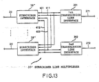
- an ISDN system comprises a first basic rate transmission line 271 connected to a first ISDN digital switch and a second basic rate transmission line 272 connected to a second ISDN switch.
- the first and second basic rate transmission lines 271 and 272 are connected to a first and a second subscriber line multiplexer 371 and 372, respectively.
- Each of the first and second subscriber line multiplexer 371 and 372 are similar to each other and comprises an arrangement similar to the subscriber line multiplexer 37 as shown in Figs. 5 and 6. Therefore, the first and second multiplexers 371 and 372 are shown to have blocks represented by the same reference numerals as in Fig. 5 and description thereto is omitted for the purpose of simplification of the description.
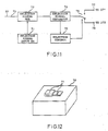
- Each of the subscribers lines 20 is coupled to the first and the second subscriber line multiplexers 371 and 372 through a line selector 70.
- the line selector 70 is for selectively connecting the corresponding subscriber line 20 to the first and the second subscriber line multiplexers 371 and 372.
- the line selector 70 comprises a selection signal input switch 71.
- the selection signal input switch 71 comprises two key switches which are numbered 1 and 2. No. 1 key switch is pushed down, a selection signal is set a binary "1" for selecting the first transmission line 271. On the other hand, No. 2 key switch is pushed down, a selection signal is set a binary of "0" for selecting the second transmission line 272.
- the subscriber line 20 is connected to a selection signal multiplexer 72 through a first port 73 so as to multiplex the basic TDM signal on the subscriber line 20 and the selection signal from the selection signal input switch 71.
- a frame of an electric signal on the basic interface comprises 48 bits and includes an unused bits called "S" bits in addition to the B channel bits, the D channel bits, and other used bits.
- the selection signal is inserted into the "S" bits by the selection signal multiplexer 72 to produce a multiplexed signal.
- the multiplexed signal is applied to a selection signal separator 74.
- the selection signal is separated from the multiplexed signal at the selection signal separator 74 and is supplied to a selection control circuit 75.
- the remaining signal that is the basic TDM signal is applied to a switch 76 which is controlled by the selection control circuit 75.
- the switch 76 has a second and a third port 77 and 78 so that the basic TDM signal from the selection signal separator 74 is selectively connected to the second and the third ports 77 and 78 by switching operation of the switch 76.
- the second port 77 and the third port 78 are connected to the first and the second subscriber line multiplexers 371 and 372.
- the switch 76 When the No. 1 key switch is pushed down, the switch 76 is connected to the second port 77 and the basic TDM signal is applied to the corresponding subscriber interface 38 in the first subscriber line multiplexer 371. Then, the basic TDM signal is converted into the primary TDM signal by the first subscriber line miltiplexer 371 in the similar fashion in the embodiment of Figs. 5 and 6 and is transmitted to the first ISDN digital switch through the transmission line 271.
- the basic TDM signal is applied to the corresponding subscriber interface 38 in the second subscriber line multiplexer 372 through the third port 78. Accordingly, the basic TDM signal will be converted to the primary TDM signal and is transmitted to the second ISDN digital switch through the second transmission line 272.
- those line selectors 70 connected thereto are adjusted to the selection signal of a binary bit "1" by pushing the No. 1 key.
- the remaining line selectors are set to generate the selection signal of binary bit "0" by pushing down No. 2 key switch.
- all of the line selectors 70 may usually be adjusted to the selection signal of a binary bit "1" so that the basic TDM signals on all of the subscriber lines 20 are supplied to the first subscriber line multiplexer 371.
- a specific line selector 70 connected to the specific subscriber line is set to produce the selection signal of a binary bit of "0" by pushing down No. 2 key switch. Then, the specific line is coupled with the private line 272 through the second subscriber line multiplexer 372.
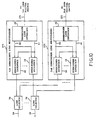
- an ISDN system has a first and a second transmission line 271 and 272 similar to the embodiment of Fig. 10.
- the first transmission line 271 is connected to a first ISDN digital switch
- the second transmission line 272 is connected to a second ISDN digital switch or is a private line for connecting to a specific external subscriber.
- a single subscriber line multiplexer 37′ comprises a first and a second transmission interface 391 and 392 which are arranged similar to each other and similar to the transmission line interface 39 in Fig. 6.
- the subscriber line multiplexer 37′ further comprises a plurality of subscriber interfaces 38 ⁇ which are connected to the first transmission line interface 391 through a first internal bus 401 and a first timing signal line 411.
- the subscriber interfaces 38 ⁇ are also connected to the second transmission line interface 392 through a second internal bus 402 and a second timing signal line 412.
- the basic TDM signal on each of the subscriber lines 20 has a selection signal in each of the "S" bits as described in connection with Fig. 11.
- the selection signal is also input to the basic TDM signal by provision of a selection signal input switch and selection signal multiplexer in TEs on the subscriber line 20 in the similar manner to those shown at 71 and 72 in Figs. 11 and 12.
- the basic TDM signal is applied from the subscriber line 20 to the corresponding one of subscriber interfaces 38 ⁇ .
- Each of the subscriber interfaces 38 ⁇ detects the selection signal in the basic TDM signal and transmits the basic TDM signal in the time division fashion to that one of the first and the second transmission lines 271 and 272 which is indicated by the selection signal.
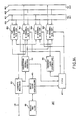
- the subscriber interface 38 ⁇ is similar to the subscriber interface 38 in Fig. 6 but further comprises a selection signal detector 80 connected to the channel multiplexer/demultiplexer 44.
- the channel multiplexer/demultiplexer 44 functions similar to the B/D channel multiplexer/demultiplexer 44 in Fig. 5 and also functions to separate the "S" bit signal from the basic TDM signal.
- the "S" bit signal represents the selection signal as described above.
- the "S" bit signal is applied to the selection signal detector 80 which decides "1" or "2" of the selection signal to produce an enabling signal and an unabling signal when the selection signal is decided.
- the subscriber interface 38 ⁇ further comprises a first and a second B channel transmitter/receiver circuit 491 and 492 which is similar to each other and similar to the B channel transmitter/receiver circuit 49 in Fig. 6. Those first and second B channel transmitter/receiver circuits 491 and 492 are connected to the channel multiplexer/demultiplexer 44 commonly. Those first and second B channel transmitter/receiver circuits 491 and 492 are also connected to the first and second transmission line interfaces 391 or 392 through the first internal bus 401 and the first timing signal line 411 and through the second internal bus 402 and the second timing signal line 412, respectively.
- the subscriber interface 38 ⁇ further comprises a first and a second D channel transmitter/receiver circuit 501 and 502 which is similar to each other and similar to the D channel transmitter/receiver circuit 50 in Fig. 6. Those first and second D channel transmitter/receiver circuits 501 and 502 are connected to the primary LAPD controller 48 commonly. Those first and second D channel transmitter/receiver circuits 501 and 502 are also connected to the first and second transmission line interfaces 391 or 392 through the first internal bus 401 and the first timing signal line 411 and through the second internal bus 492 and the second timing signal line 412, respectively.
- the selection signal detector 80 decides "1"
- the selection signal detector 80 delivers the enabling signal to the first B channel transmitter/receiver circuit 491 and the first D channel transmitter/receiver circuit 501 and delivers the unabling signal to the second B channel transmitter/receiver circuit 492 and the second D channel transmitter/receiver circuit 502.
- the subscriber interface 80 transmits and receives the primary TDM signal to and from the first transmission line 271 through the first B channel transmitter/receiver circuit 491, the first D channel transmitter/receiver circuit 501, the first transmission line interface 391, in the similar manner of the embodiment in Figs. 5 and 6.
- the selection signal detector 80 decides "0"
- the selection signal detector 80 delivers the enabling signal to the second B channel transmitter/receiver circuit 492 and the second D channel transmitter/receiver circuit 502 and delivers the unabling signal to the first B channel transmitter/receiver circuit 491 and the first D channel transmitter/receiver circuit 501.
- the subscriber interface 38 ⁇ transmits and receives the primary TDM signal to and from the second transmission line 272 through the second B channel transmitter/receiver circuit 492, the second D channel transmitter/receiver circuit 502, the second transmission line interface 392, in the similar manner of the embodiment in Figs. 5 and 6.
- the selection signal input switch is pushed down in a specific one of TEs to select one of the first transmission lines 271 and 272, the specific TE is connected to the selected one of the first and second transmission lines 271 and 272.
Abstract
Description
- The present invention relates to an integrated services digital network (ISDN) system according to recommendations of the CCITT (International Telegraph and Telephone Consultative Communication) and, in particular, to subscriber line multiplexing for multiplexing signals, particularly, control signals on a plurality of subscriber lines on a high rate digital transmission line extending to an ISDN digital switch.
- In the ISDN system, a plurality of subscriber lines extend from an exchanging office to user areas. Each subscriber line terminates to a network termination (NT) unit. A user bus is connected to the NT unit and extended in the user area. One or more user's equipments or terminal equipments (TEs) such as a digital telephone set or sets (which will only be called telephone sets hereinafter), a facsimile set or sets, a personal computer set or sets, and the like.
- The CCITT recommendations I series prescribes protocol or user-network connection or interface in connection with seven classified layers which are numbered by 1 through 7. For example,
layer 1 is directed to physical connecting conditions such as transmission rate, pin number of connectors and others,layer 2 being for data link,layer 3 for call control from a call setup to call release completion. - According to the I series, communication information and control signal are transmitted through different channels which are multiplexed in a time division fashion. The communication information channel is called a B channel and the control information channel is referred to as a D channel. It is possible to transmit communication information through the D channel.
- As a basic one of user-network interface structures, a basic interface is determined which comprises two B channels of a transmission rate of 64 kbps which are separately called B1 and B2 channels and a single D channel of a transmission rate of 16 kbps.
- Another user-network interface structure is called a primary rate interface which comprises 23 B channels of 64 kbps and a single D channel of 64 kbps.
- As will be noted from the above description, the single D channel is commonly used by a plurality of TEs connected in the user bus.
- In connection with the
layer 2 for data link, a plurality of logical connections or links are made on the D channel by use of LAPD (Link Access Procedure on D channel). Various control information inlayer 2 andlayer 3 can be transmitted through the links. A frame format of the LAPD is in conformity with the HDLC (High-level Data Link Control Procedure) and comprises a start flag, an address field, a control field, an information field, a frame check sequence and a stop flag. The frame format will later be described in detail with reference to the drawings. - The address field is rewritable to identify each one logical link. The control field is used for type identification of the LAPD frame itself. There are defined a number of types for the LAPD frame. For example, I (Information) frame is used for information transfer in a multiframe mode and UI (Unnumbered Information) frame is used for information transfer in an unacknowledged information transfer mode.
- Transfer of call control information in the
layer 3 is performed by use of the I frame or the UI frame. The call control information is inserted in the information field in each of the I and UI frames as alayer 3 message. A format of thelayer 3 message comprises a common information portion and an individual information portion. The common information portion comprises a protocol discriminator for identifying thelayer 3 message, a call reference for referring to a call, and a message type. There are a number of types for thelayer 3 message, for example, SETUP for identifying a call request, REL COMP for identifying notice of completion of channel disconnection and release completion of a call reference, and others. - A large number of subscriber lines are extended from an exchange office having an ISDN digital switch to various users. When a user such as a company has a plurality of subscriber lines, it is advantageous to multiplex those subscriber lines into a single transmission line through which signals on the plurality of subscriber lines are transmitted as a TDM (time division multiplexed) signal. That is, B channel signals and D channel signals on a plurality of subscriber lines are time-division multiplexed and are transmitted through the signal transmission line.
- Providing that each subscriber line is dependent on the basic interface having two B channels of 64 kbps and a single D channel of 16 kbps and that a primary rate digital transmission line (1544 kbps, 23B + D channels) is used for the single transmission line, only four D channels (64/16 = 4) can be multiplexed.
- In order to resolve the problem, the Bell Communications Research, Inc. proposed a "Statistical Multiplexing" in Bell Communications Research Technical Advisory, TA-TSY-000397, May 2, 1987 (Reference 1). According to the Statistical Multiplexing, 16 D channel signals on subscriber lines of the basic interface are statistically multiplexed into a D channel on the primary rate transmission line. In order to identify each subscriber line and to identify multiplex, the identification information is tagged to the D channel information on each subscriber line to form a new D channel signal which is transmitted to the transmission line in the statistical multiplexing. The new D channel signal will later be described in detail in connection with the drawings.
- According to the statistical multiplexing, an increased number of D channels can be multiplexed in comparison with the conventional time division multiplexing. However, a data link is still set up between a TE on one subscriber line and an ISDN switch or exchanger so that it is impossible to reduce load of the ISDN switch.
- In multiplexing of a plurality of subscriber lines, it is impossible to handle those lines which belong to different exchange offices.
- In another ISDN system, a private line or a privately used line is used. It is also impossible in the multiplexing to handle the private line and subscriber lines which belong to an exchange office together.
- Therefore, it is an object of the present invention to provide an ISDN system having a subscriber line multiplexer wherein load of an ISDN switch can be reduced.
- It is another object of the present invention to provide an ISDN system having a subscriber line multiplexer which can process subscriber lines which belong to different exchange offices.
- It is still another object of the present invention to provide an ISDN system having a subscriber line multiplexer which enables subscriber lines to connect to a private line.
- The present invention is applicable to an ISDN (Integrated Services Digital Network) system comprising a plurality of subscriber lines associated with a plurality of terminal equipments, a subscriber line multiplexer connected to the plurality of subscriber lines, each of the subscriber lines transmitting a basic TDM (Time Division Multiplex) signal between the plurality of terminal equipments and the subscriber line multiplexer at a basic transmission rate, the terminal equipments having different terminal equipment TEIs (Terminal Endpoint Identifiers) assigned thereto as basic TEIs, respectively, the basic TDM signal comprising a plurality of basic information channels for transmitting information and a basic control channel for transmitting a basic control signal, the basic control signal comprising a specific one of the basic TEIs and control information from a specific one of the terminal equipments, a first ISDN digital switch having a TEI list for registering TEIs, and a high rate transmission line coupling the subscriber line multiplexer and the first ISDN digital switch for transmitting a secondary TDM signal therebetween at a primary transmission rate higher than the basic transmission rate, the primary TDM signal comprising a plurality of primary information channels and a primary control channel, the subscriber line multiplexer statistically multiplexing the basic control channel signals on the plurality of subscriber lines into the primary control channel to thereby transmit the control information to the first ISDN digital switch. According to the present ivnention, the subscriber line multiplexer comprises a plurality of subscriber interface means coupled to the plurality of subscriber lines, respectively and internal bus means coupled to the high rate transmission line and commonly connected to the plurality of subscriber interface means. Each of the subscriber interfaces comprises channel separating means coupled with each one of the subscriber lines for separating the basic control channel signal from the basic TDM signal to produce a separated signal, basic TEI list for memorizing the basic TEIs, basic control means responsive to the separated signal for deriving the control information as a derived conrol information, the basic control means establishing a basic data link between the specific terminal equipment and the basic control means through the basic control channel in cooperation with the basic TEI list, primary control means having a subscriber TEI assigned to the each one of the subscriber line interface means as a primary TEI which is registered in the TEI list as a primary TEI list of the first ISDN digital switch, the primary control means responsive to the derived control information for making a primary control signal which comprises the primary TEI and the derived control information without the specific basic TEI, and transmitting means for transmitting the primary control signal into the primary control channel through the internal bus in the statistical multiplexing fashion so that a primary data link is established between the primary control means and the first ISDN digital switch through the primary control channel in cooperation with the primary TEI list.
- The subscriber line multiplexer may further comprise transmission line interface means coupled to the high rate transmission line for detecting the secondary TDM signal on the high rate transmission line to produce a timing signal, the transmission line interface means being connected to the internal bus means for coupling the internal bus means to the high rate transmission line, and a timing signal line connecting the transmission line interface means to the plurality of subscriber interface means for delivering the timing signal to the plurality of subscriber interface means, the transmitting means detecting the primary control channel based on the timing signal.
- According to an aspect of the pesent invention, the ISDN system may further comprise a second ISDN digital switch and cross connecting means for selectively coupling the high rate transmission line to one of the first and second ISDN digital switches. Each of the subscriber interface means further comprises setting means for setting a switch selection code for selecting one of the first and second ISDN digital switches. The switch selection code is contained in the primary control signal together with the primary TEI. The cross connecting means comprises detecting means for detecting the switch selection code in the primary control signal to deliver the secondary control signal to that one of the first and second ISDN digital switches which is identified by the switch selection code.
- According to another aspect of the present invention, the ISDN system may further comprise an additional high rate transmission line coupled to the subscriber line multiplexer. Each of the terminal equipments being provided with means for generating line selection signal for selecting one of the high rate transmission line and the additional high rate transmission line. The selection signal is contained in the basic TDM signal to be delivered to the subscriber multiplexer. Each of the subscriber line interface means further comprises additional transmitting means connected to the primary control means for transmitting the primary control signal onto the additional high rate transmission line, and selection signal detector means coupled to each one of the subscriber lines for detecting the line selection signal to produce an enabling signal and an unabling signal, the enabling signal being delivered to one of the transmitting means and the additional transmitting means to transmit the primary control signal to one of the high rate transmission line and the additional high rate transmission line which is identified by the line selection signal, while the unabling signal being delivered to the other of the transmitting means and the additional transmitting means.
- The invention is further described in connection with the drawing in which
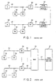
- Fig. 1 is a block diagram view of a known ISDN system;
- Fig. 2 is a block diagram view of another ISDN system wherein signals on a plurality of subscriber lines are multiplexed in the time division fashion so as to be transmitted to an ISDN digital switch through a single line;
- Fig. 3 shows various frame formats of D channel signal used in the system of Fig. 2;
- Fig. 4 shows frame formats of the D channel signal used in the present invention;
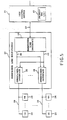
- Fig. 5 is a block diagram view of an ISDN system using a subscriber line multiplexer according to an embodiment of the present invention;
- Fig. 6 is a block diagram view of a subscriber interface used in Fig. 5;
- Fig. 7 is a block diagram view of an ISDN system according to a second embodiment of the present invention wherein a plurality of subscriber lines are cross-connected to different ISDN digital switch;
- Fig. 8 is a front view of a subscriber interface used in the subscriber line multiplexer according to the second embodiment;
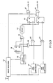
- Fig. 9 is a circuit diagram view of a cross connector in Fig. 7;
- Fig. 10 is a block diagram view of a main portion of a third embodiment;
- Fig. 11 is a block diagram view of a line selector in Fig. 10;
- Fig. 12 is a perspective view of the line selector of Fig. 11;
- Fig. 13 is a block diagram view of a portion of a fourth embodiment; and
- Fig. 14 is a block diagram view of a subscriber interface in Fig. 13.
- Prior to description of embodiments, a known ISDN will be described for the purpose of better understanding of the present invention.
- Referring to Fig. 1, a plurality of digital subscriber lines (DSLs) 20 are connected to at least one ISDN digital switch or
exchanger 21. In the figure, two ISDNdigital switches 21 are shown to be connected through an inter-office line. Each ofDSLs 20 is terminated at an individual network termination (NT)unit 22. TheNT unit 22 is connected to asubscriber bus 23 to which a plurality of terminal equipments (TEs) 24, for example, digital telephone sets, facsimile sets, personal computers, and the like are connected in a parallel form. Eachsubscriber bus 23 is terminated to aterminal resistor 25 at an extended end. - In the system, communication can be performed between one or
more TEs 24 in onesubscriber bus 23 and one ormore TEs 24 on another subscriber bus through the ISDN digital switch or switches 21. - The shown ISDN system is arranged dependent on the CCITT recommendations described in the preamble. For example, the basic interface is used between the
bus 23 and theNT 22. That is, two B channel signals and a single D channel signal are transmitted onbus 23 andsubscriber line 20 between NTs and the ISDNdigital switch 21 throughNT 22. According to the D channel protocol forlayers - Referring to Fig. 3, an
LAPD frame 31 comprises a start flag field (FRAG) of one octet length, an address field (ADDRESS) of two octet length, a control field (CONTROL) of one octet length, an information field (INFORMATION) of a variable length (260 octets at maximum), a frame check sequence (FRAME CHECK SEQUENCE) of one or two octet length, and a stop flag field (FRAG) of one octet length. - Various frame types such as I, UI, and others are determined for the LAPD frame and each type is identified in the control field as described in the preamble.
- The address field comprises EA0 of one bit, C/R of one bit, SAPI of 6 bits, EA1 of one bit and TEI of 7 bits similar to a frame portion as shown at 33 in Fig. 3. EA is an address extension bit and EA0 means continuation to the next octet while EA1 means a last octet in the field. C/R is for indication of which the frame is command or response. SAPI is a service access point identifier and TEI is a terminal endpoint identifier. SAPI can take a value from 0 to 63 and several functions are determined for several values, for example, SAPI=0 means that the frame is for call control signal while the remaining values are not yet determined. TEI can take a value from 0 to 127 and TEI values from 64 to 126 are assigned to
TEs 24 in each user and registered in a TEI list (not shown) in the ISDNdigital switch 21. Values from 0 to 63 are left for free use by users and the remaining value 127 is determined to identify a broadcasting mode. - The TEI value is not fixed to a specific TE but is assigned to each TE when connected to the subscriber line in order to insure portability of TEs.
- TEI assignment procedure is also determined in the I series of the CCITT recommendations and is performed between the TE and the ISDN digital switch by use of the UI frame of the LAPD with SAPI=63 and TEI=127 being set in the address field when the TE is connected to the subscliber line connected to the ISDN digital switch. Detail of the assignment procedure is not described herein but will be understood by reference to the I series.
- In order to reduce the number of
subscriber lines 20 extending from thedigital switch 21 to a user such as a company, a plurality of subscriber lines are multiplexed to a high rate transmission line such as a primary rate transmission line, as described in the preamble. - Referring to Fig. 2, a remote digital terminal (RDT) 26 is connected to a primary
rate transmission line 27 extending from the ISDNdigital switch 21. A plurality ofsubscriber lines 20 are connected toRDT 26, and each subscriber line is provided withNT 22, auser bus 23, and a plurality ofTEs 24 connected to theuser bus 23. B channel signals and D channel signals on thesubscriber lines 20 are multiplexed in the time division fashion and are transmitted through the primaryrate transmission line 27 to the ISDN digital switch. - Bell proposed the "Statistical Multiplexing" in
Reference 1 as described in the preamble to enable to multiplex an increased number of D channel signals. - In order to insure the statistical multiplexing, Bell uses a new LAPD frame format.
- Referring to Fig. 3, the new
LAPD frame format 32 is characterized by insertion of theLAPD frame 31 on the subscriber channel into an information field of thenew LAPD frame 32, although the start and stop flags (FLAG) inframe 31 are removed. Accordingly, the new LAPD frame format is appreciated as a multiple LAPD frame format. Further, in the new LAPD frame, SAPI in the address field is fixed to be avalue 32 which is determined to identify the new frame after multiplication, as shown at 33 in Fig. 3. One of values from 1 to 16 is assigned to TEI in the same address field as DSL numbers, as shown below theaddres field format 33 in Fig. 3. - UI is inserted in a control field (CONTROL) of the new LAPD format so that the new frame is the UI frame.
- According to the statistical multiplexing manner using the new or multiple LAPD frame, the ISDN
digital switch 21 must process two control information sets for two TEIs in one D channel signal. This means that load of the ISDN digital switch is not decreased but increased. - The present invention aims to reduce load of the ISDN digital switch in use of the statistical multiplexing of D channel signals on a plurality of subscriber lines. A fundamental concept of the present invention will be described below.
- Referring to Fig. 4, the
LAPD frame 31 of the D channel signal on the subscriber line is shown together with the address field (ADDRESS) 34 and has been described in connection with Fig. 3. AnotherLAPD frame 35 is also shown together with itsaddress field 36 and has a format similar to theLAPD frame 31. - According to the present invention, the
LAPD frame 31 on the basic interface is converted into theother LAPD frame 35 which is then transmitted onto a high rate or primary rate transmission line in the statistical multiplexing fashion. Accordingly, theLAPD frame 31 will be called a basic LAPD frame and its various fields will be referred to as individual field names with a term of "basic" being prefixed to the names. On the other hand, theother LAPD frame 35 will be called a primary LAPD frame and its individual field names will be called individual field names with a term "primary" being prefixed to the names. - In the
basic address field 34 in the basic LAPD frame, SAPI is set to be 0 for the call control and TEI is set as a value (64-126) assigned to a TE which originates the D channel signal. TEI inserted in thebasic address field 34 will be called a basic TEI and is not registered in the TEI list in the ISDN digital switch but is registered in a basic TEI list provided in a subscriber line multiplexer which will later be described in connection with Fig. 5. - In the multiplexer, the
primary LAPD frame 35 is formed. The basic information field in theframe 31 is copied into a primary information field (INFORMATION) in theprimary frame 35. A primary control field in theprimary LAPD frame 35 can take a control field information such as UI or I necessary between the multiplexer and the ISDN digital switch. Therefore, in some cases, the primary control field is same as the basic control field, but in other cases the primary control field is different from the basic control field. TEI in theprimary address field 36 is not similar to the basic TEI but is a value assigned to the subscriber and registered to the primary TEI list in the ISDN digital switch. The TEI in theprimary frame 35 will be referred to as a primary TEI. - In
layer 3 for call control, the basic TEI is written intolayer 3 message as a part of the call reference in order to enable to distinguish the TE originating the call request. - The call reference area in the
layer 3 message has an increased portion of one octet in the primary rate interface in comparison with the basic interface. The basic TEI is written into the increased portion in the primary LAPD frame. - A plurality of primary LAPD frame signals formed for the subscriber lines are transmitted to the ISDN digital switch through a primary rate transmission line after statistically multiplexed.
- According to the procedure of the present invention, the basic information from a TE can be transferred to the ISDN digital switch reliably but the ISDN digital switch need not process two control information sets for two TEIs. That is, the subscriber lines are seen from the ISDN digital switch as if they are terminal equipments in the conventional system. The multiplexer distinguishes TEs on a subscriber line by the TEIs. Accordingly, the ISDN digital switch is freed from an excessive load.
- Referring to Fig. 5, the shown ISDN system is similar to that in Fig. 2 and the similar portions are represented by the same reference numerals.
- In the system of the embodiment, a
subscriber line multiplexer 37 is corresponding to theRDT 26 in Fig. 2 but is different from theRDT 26. Thesubscriber line multiplexer 37 is for performing the conversion from the basic LAPD frame to the primary LAPD frame and also performing the time division multiplexing of the primary LAPD frame signals in the statistical multiplexing fashion. Thesubscriber line multiplexer 37 comprises a plurality ofsubscriber interfaces 38 connected to a plurality ofsubscriber lines 20, atransmission line interface 39 connected to therate transmission line 27, aninternal bus 40 connecting the plurality ofsubscriber interfaces 38 to thetransmission line interface 39 commonly, and atiming signal line 41 for supplying a timing signal from thetransmission line interface 39 to subscriber interfaces 38. Thesubscriber interface 38 actually performs the conversion from the basic LAPD frame to the primary LAPD frame and transmits the primary LAPD frame signal to theinternal bus 40 for performing the statistical multiplexing with like primary LAPD frame signals from theother subscriber interfaces 38 to produce the multiplexed signal. Thetransmission line interface 39 is for detecting a frame on the TDM signal on the primaryrate transmission line 27 to produce the timing signal and for transmitting the multiplexed signal on theinternal bus 40 to thetransmission line 27, after adding a frame bit or a synchronization bit. - In the shown embodiment, NTs are not used and
TEs 24 are directly connected to the subscriber lines 20. That is, the subscriber interfaces 38 function as the network terminations. The ISDNdigital switch 21 is shown to have the TEI list as aprimary TEI list 42 which is for registering the primary TEI as described in connection with Fig. 4. - Now, the TDM signal on each of the
subscriber lines 20 is called a basic TDM signal and the B channel and the D channel in the basic TDM signal are called a basic B channel and a basic D channel, respectively. On the other hand, the TDM signal on thetransmission line 27 is called a primary TDM signal and the B channel and the D channel in the primary TDM signal are called a primary B channel and a primary D channel, respectively. - Referring to Fig. 6, each of the
subscriber interface 38 comprises a B/D channel multiplexer/demultiplexer (MUX/DMUX) 44, abasic LAPD controller 45, abasic TEI list 46, a central processing unit (CPU) 47, aprimary LAPD controller 48, a B channel transmitter/receiver (T/R)circuit 49, and D channel transmitter/receiver (T/R)circuit 50. - A basic TDM signal (2B + D for the basic interface) is supplied to the B/D channel multiplexer/
demultiplexer 44 from thesubscriber line 20. The B/D channel multiplexer/demultiplexer 44 is for separating the D channel signal or the basic control signal from the basic TDM signal as a separated signal having thebasic LAPD frame 31 in Fig. 4. The B/D channel multiplexer/demultiplexer 44 serves as a channel separator. The separated signal is applied to thebasic LAPD controller 45 while the basic B channel signal is subjected to the rate adaptation and then supplied to the B channel transmitter/receiver circuit 49 as the primary B channel signal. - The
basic LAPD controller 45 refers to thebasic TEI list 46 and removes the basic start and stop flag portions, the basic address field, the basic control field, and the basic frame check sequence from the derived signal (31 in Fig. 4) under control of thecentral processing unit 47 when the TEI in the basic address field (34 in Fig. 4) is registered in thebasic TEI list 46. The remaining basic information field in the basic LAPD frame (31) of the derived signal is supplied to thecentral processing unit 47 and applied to theprimary LAPD controller 48 therefrom. Theprimary LAPD controller 48 holds the primary TEI which is assigned to thesubscriber interface 38 itself and registered in the primary TEI list in the ISDNdigital switch 42. Theprimary LAPD controller 48 receives the basic information field and forms the primary LAPD frame (35 in Fig. 4) signal or the primary control signal. Therefore, thebasic LAPD controller 45, thebasic TEI list 46, thecentral processing unit 47, and theprimary LAPD controller 48 function to convert the basic control signal into the primary control signal. - Assignment of the basic TEI and registration of the basic TEI in the
basic TEI list 46 can be performed between each one of theTEs 24 and thecorresponding subscriber interface 38 according to a procedure similar to the TEI assignment procedure determined by the I series. The primary TEI is assigned and registered inprimary TEI list 42 according to the similar assignment procedure performed between each one of the subscriber interfaces 38 and theISDN switch 21. - The primary control signal is applied to the D channel transmitter/
receiver circuit 50 and is transmitted into an unused time slot in the primary D channel on theinternal bus 40 at a timing according to the timing signal applied thereto through thetiming signal line 41. Thus, a plurality of primary control signals made in the vicinity ofsubscriber interface 38 are statistically multiplexed in the primary D channel. - While, the primary B channel signal is transmitted in a primary B channel on the
internal bus 40 from the B channel transmitter/receiver circuit 49 in the time division fashion so that basic B channel signals in the plurality of the subscriber interfaces 38 are multiplexed. Thus, the primary TDM signal carries the primary B channel signals and the primary control signals to the ISDNdigital switch 21 through the primaryrate transmission line 27. - In receiving the primary TDM signal originated by the ISDN
digital switch 21, the D channel transmitter/receiver circuit 50 receives the primary D channel signal which is supplied to theprimary LAPD controller 48. When theprimary LAPD controller 48 detects the own primary TEI assigned to thesubscriber interface 38 itself in one of the primary control signals in the primary D channels, theprimary LAPD controller 48 derives the primary information field in the primary control signal (35 in Fig. 4). The derived primary information field is supplied to thebasic LAPD controller 45 through thecentral processing unit 47. Thebasic LAPD controller 45 cooperates with thecentral processing unit 47 and thebasic TEI list 46 and forms the basic control signal of the basic LAPD frame (31 in Fig. 4) in which the derived primary information field is written into the basic information field and the basic address field, respectively. Thus, thebasic LAPD controller 45, thebasic TEI list 46, thecentral processing unit 47, and theprimary LAPD 48 function to convert the primary control signal to the basic control signal. The converted basic control signal is supplied to the B/D channel multiplexer/demultiplexer 44. - The B channel transmitter/
receiver circuit 49 receives the primary B channel signal in a specific one of primary B channels on the primary TDM signal indicated by thecentral processing unit 47. The primary B channel signal is subjected to the rate adaptation and is also supplied to the B/D channel multiplexer/demultiplexer 44 as a basic B channel signal. The B/D channel multiplexer/demultiplexer 44 multiplexes the basic control signal supplied from thebasic LAPD controller 45 and the basic B channel signal supplied from the B channel transmitter/receiver circuit 49 to form the basic TDM signal which is transmitted to the subscriber line connected to thesubscriber interface 38. One ofTEs 24 on thesubscriber line 20 receives the basic control signal according to the basic TEI in the signal. - In the embodiment, a basic data link is established by the basic LAPD signal between one of
TE 24 on thesubscriber line 20 and thesubscriber interface 38 connected thereto. While, a primary data link is also established by the primary LAPD signal between thesubscriber interface 38 and the ISDNdigital switch 21. Accordingly, theISDN signal switch 21 only processes the primary control signal so that theISDN switch 21 has a reduced load. Thesubscriber interface 38 serves as a switch forTEs 24 on thecorresponding subscriber line 20 for the D channel signal. - Referring to Fig. 7, ISDN system shown therein comprises a first and a second ISDN
digital switches subscriber line multiplexer 37 similar to that in Figs. 5 and 6, and across connector 52 for cross connecting the basicrate transmission line 27 to the first and the second ISDN digital switch. One of the subscriber lines belongs to not the first ISDNdigital switch 21 but the second ISDNdigital switch 51. Therefore, the one subscriber line is depicted by 20′ and the corresponding subscriber interface is represented by 38′. The remainingsubscriber lines 20 belong to the firstdigital switch 21. - Referring to Fig. 8, each of the subscriber interfaces 38 and 38′ is provided with a setting
switch 53 for manually setting a switch selection code identifying one of the first and second ISDNdigital switches digital switches switch 53 is set to No. 1, the switch selection code is 1 and is held in the primary LAPD controller (48 in Fig. 6) in thecorresponding subscriber interface 38. On the other hand, the settingswitch 53 is set to be 2 in thesubscriber interface 38′ and the selection code of 2 is held in theprimary LAPD controller 48 in thesubscriber interface 38′. The switch selection code is written into the primary address field in the primary LAPD frame signal together with the primary TEI when theprimary LAPD controller 48 forms the primaryLAPD frame signal 35 in Fig. 4. - The
cross connector 52 comprises a detecting means for detecting the switch selection code in the primary control signal in the primary D channel on thetransmission line 27. When the detecting means detects the selection signal, thecross connector 52 delivers the primary control signal to one of the first and second ISDNdigital switches - Referring to Fig. 9, the
cross connector 52 comprises ashift register 54 for receiving the primary TDM signal on thetransmission line 27 which signal is shifted therein one by one bit. Theshift register 54 is connected to aflag comparator 55 at a predetermined stage and is commonly connected to a first and asecond code comparator register 54 so that the switch selection code is checked by the first andsecond code comparators flag comparator 55. - When the flag is detected by the
flag comparator 55, a detected signal is delivered to aflipflop 58, and ANDgates flipflop 58 is set and the ANDgate 60 is opened while the ANDgate 59 is closed. - The
first code comparator 56 has areference value 1 and compares the switch selection code in the primary TEI field with thevalue 1. When the selection code is 1, thecode comparator 56 produces a first code detecting signal which is then supplied to aflipflop 61 through an ANDgate 62. Then, theflipflop 61 is set and another ANDgate 63 is open. Thus, the primary control signal in theshift register 54 is delivered to the first ISDNdigital switch 21 through the ANDgate 63. - When the selection code is 2, the
second code comparator 57 produces a second code detecting signal which sets aflipflop 64 through an ANDgate 65. Accordingly, an ANDgate 66 is open and the primary control signal is delivered from theshift register 54 to the second ISDN digital switch through the ANDgate 66. - The first and
second code comparators cross connector 52 as described above. - Thereafter, when the flag is detected by the
flag comparator 55, thecomparator 55 again produces the detected signal which resets theflipflop 58. Then, the ANDgate 59 is open and the ANDgate 60 is closed. The detected signal is applied to adelay circuit 67 through the ANDgate 59 and resets that one of theflipflops delay circuit 67. Then, the corresponding one of the ANDgates shift register 54. - In the manner as described above, the primary control signal is cross connected to one of the first and the second ISDN
digital switches - Returning to Fig. 8, each of the subscriber interfaces 38 and 38′ can be provided with a manual
TEI setting switch 68. As a result, the primary TEI is manually set by themanual setting switch 68. When the primary TEI is set by theswitch 68, the primary TEI assignment and registration procedure is performed according to the I series of the CCITT as described above between thesubscriber interface digital switch digital switch lamp 69 on thesubscriber interface manual setting switch 68 is again operated to set a fresh primary TEI. After repetition of the operation, thelamp 69 is extinguished when the manually set TEI is consistent with a TEI assigned by the first or the second ISDNdigital switch - Referring to Fig. 10, an ISDN system according to another embodiment comprises a first basic
rate transmission line 271 connected to a first ISDN digital switch and a second basicrate transmission line 272 connected to a second ISDN switch. - The first and second basic
rate transmission lines subscriber line multiplexer subscriber line multiplexer subscriber line multiplexer 37 as shown in Figs. 5 and 6. Therefore, the first andsecond multiplexers - Each of the subscribers lines 20 is coupled to the first and the second
subscriber line multiplexers line selector 70. Theline selector 70 is for selectively connecting thecorresponding subscriber line 20 to the first and the secondsubscriber line multiplexers - Referring to Fig. 11, the
line selector 70 comprises a selectionsignal input switch 71. - Referring to Fig. 12, the selection
signal input switch 71 comprises two key switches which are numbered 1 and 2. No. 1 key switch is pushed down, a selection signal is set a binary "1" for selecting thefirst transmission line 271. On the other hand, No. 2 key switch is pushed down, a selection signal is set a binary of "0" for selecting thesecond transmission line 272. - The
subscriber line 20 is connected to aselection signal multiplexer 72 through afirst port 73 so as to multiplex the basic TDM signal on thesubscriber line 20 and the selection signal from the selectionsignal input switch 71. - According to the I series of the CCITT, a frame of an electric signal on the basic interface comprises 48 bits and includes an unused bits called "S" bits in addition to the B channel bits, the D channel bits, and other used bits.
- The selection signal is inserted into the "S" bits by the
selection signal multiplexer 72 to produce a multiplexed signal. - The multiplexed signal is applied to a
selection signal separator 74. The selection signal is separated from the multiplexed signal at theselection signal separator 74 and is supplied to aselection control circuit 75. The remaining signal that is the basic TDM signal is applied to aswitch 76 which is controlled by theselection control circuit 75. - The
switch 76 has a second and athird port selection signal separator 74 is selectively connected to the second and thethird ports switch 76. Thesecond port 77 and thethird port 78 are connected to the first and the secondsubscriber line multiplexers - When the No. 1 key switch is pushed down, the
switch 76 is connected to thesecond port 77 and the basic TDM signal is applied to thecorresponding subscriber interface 38 in the firstsubscriber line multiplexer 371. Then, the basic TDM signal is converted into the primary TDM signal by the firstsubscriber line miltiplexer 371 in the similar fashion in the embodiment of Figs. 5 and 6 and is transmitted to the first ISDN digital switch through thetransmission line 271. - On the contrary, when No. 2 key switch is pulsed down, the basic TDM signal is applied to the
corresponding subscriber interface 38 in the secondsubscriber line multiplexer 372 through thethird port 78. Accordingly, the basic TDM signal will be converted to the primary TDM signal and is transmitted to the second ISDN digital switch through thesecond transmission line 272. - In the actual use, when one or more of the
subscriber lines 20 belong to the first ISDN digital switch, thoseline selectors 70 connected thereto are adjusted to the selection signal of a binary bit "1" by pushing the No. 1 key. The remaining line selectors are set to generate the selection signal of binary bit "0" by pushing down No. 2 key switch. - When all of the
subscriber lines 20 belong to the first ISDN digital switch and when thesecond transmission line 272 is a private line connected to an external subscriber unit, all of theline selectors 70 may usually be adjusted to the selection signal of a binary bit "1" so that the basic TDM signals on all of thesubscriber lines 20 are supplied to the firstsubscriber line multiplexer 371. When it is desired to connect a specific one of the subscriber with theprivate line 272, aspecific line selector 70 connected to the specific subscriber line is set to produce the selection signal of a binary bit of "0" by pushing down No. 2 key switch. Then, the specific line is coupled with theprivate line 272 through the secondsubscriber line multiplexer 372. - Referring to Fig. 13, an ISDN system according to another embodiment has a first and a
second transmission line first transmission line 271 is connected to a first ISDN digital switch, while thesecond transmission line 272 is connected to a second ISDN digital switch or is a private line for connecting to a specific external subscriber. - A single
subscriber line multiplexer 37′ comprises a first and asecond transmission interface transmission line interface 39 in Fig. 6. - The
subscriber line multiplexer 37′ further comprises a plurality ofsubscriber interfaces 38˝ which are connected to the firsttransmission line interface 391 through a firstinternal bus 401 and a firsttiming signal line 411. The subscriber interfaces 38˝ are also connected to the secondtransmission line interface 392 through a secondinternal bus 402 and a secondtiming signal line 412. - The basic TDM signal on each of the
subscriber lines 20 has a selection signal in each of the "S" bits as described in connection with Fig. 11. The selection signal is also input to the basic TDM signal by provision of a selection signal input switch and selection signal multiplexer in TEs on thesubscriber line 20 in the similar manner to those shown at 71 and 72 in Figs. 11 and 12. - The basic TDM signal is applied from the
subscriber line 20 to the corresponding one ofsubscriber interfaces 38˝. Each of thesubscriber interfaces 38˝ detects the selection signal in the basic TDM signal and transmits the basic TDM signal in the time division fashion to that one of the first and thesecond transmission lines - Referring to Fig. 14, the
subscriber interface 38˝ is similar to thesubscriber interface 38 in Fig. 6 but further comprises aselection signal detector 80 connected to the channel multiplexer/demultiplexer 44. The channel multiplexer/demultiplexer 44 functions similar to the B/D channel multiplexer/demultiplexer 44 in Fig. 5 and also functions to separate the "S" bit signal from the basic TDM signal. The "S" bit signal represents the selection signal as described above. The "S" bit signal is applied to theselection signal detector 80 which decides "1" or "2" of the selection signal to produce an enabling signal and an unabling signal when the selection signal is decided. - The
subscriber interface 38˝ further comprises a first and a second B channel transmitter/receiver circuit receiver circuit 49 in Fig. 6. Those first and second B channel transmitter/receiver circuits demultiplexer 44 commonly. Those first and second B channel transmitter/receiver circuits internal bus 401 and the firsttiming signal line 411 and through the secondinternal bus 402 and the secondtiming signal line 412, respectively. - The
subscriber interface 38˝ further comprises a first and a second D channel transmitter/receiver circuit receiver circuit 50 in Fig. 6. Those first and second D channel transmitter/receiver circuits primary LAPD controller 48 commonly. Those first and second D channel transmitter/receiver circuits internal bus 401 and the firsttiming signal line 411 and through the secondinternal bus 492 and the secondtiming signal line 412, respectively. - When the
selection signal detector 80 decides "1", theselection signal detector 80 delivers the enabling signal to the first B channel transmitter/receiver circuit 491 and the first D channel transmitter/receiver circuit 501 and delivers the unabling signal to the second B channel transmitter/receiver circuit 492 and the second D channel transmitter/receiver circuit 502. Accordingly, thesubscriber interface 80 transmits and receives the primary TDM signal to and from thefirst transmission line 271 through the first B channel transmitter/receiver circuit 491, the first D channel transmitter/receiver circuit 501, the firsttransmission line interface 391, in the similar manner of the embodiment in Figs. 5 and 6. - When the
selection signal detector 80 decides "0", theselection signal detector 80 delivers the enabling signal to the second B channel transmitter/receiver circuit 492 and the second D channel transmitter/receiver circuit 502 and delivers the unabling signal to the first B channel transmitter/receiver circuit 491 and the first D channel transmitter/receiver circuit 501. Accordingly, thesubscriber interface 38˝ transmits and receives the primary TDM signal to and from thesecond transmission line 272 through the second B channel transmitter/receiver circuit 492, the second D channel transmitter/receiver circuit 502, the secondtransmission line interface 392, in the similar manner of the embodiment in Figs. 5 and 6. - Thus, when the selection signal input switch is pushed down in a specific one of TEs to select one of the
first transmission lines second transmission lines
Claims (6)
a plurality of subscriber interface means coupled to said plurality of subscriber lines, respectively; and
internal bus means coupled to said high rate transmission line and commonly connected to said plurality of subscriber interface means;
each of said subscriber interfaces comprising:
channel separating means coupled with each one of said subscriber lines for separating said basic control channel signal from said basic TDM signal to produce a separated signal;
basic TEI list for memorizing said basic TEIs;
basic control means responsive to said separated signal for deriving said control information as a derived control information, said basic control means establishing a basic data link between said specific terminal equipment and said basic control means through said basic control channel in cooperation with said basic TEI list;
primary control means having a subscriber TEI assigned to said each one of said subscriber line interface means as a primary TEI which is registered in said TEI list as a primary TEI list of said first ISDN digital switch, said primary control means responsive to said derived control information for making a primary control signal which comprises said primary TEI and said derived control information without said specific basic TEI; and
transmitting means for transmitting said primary control signal into said primary control channel through said internal bus in the statistical multiplexing fashion so that a primary data link is established between said primary control means and said first ISDN digital switch through said primary control channel in cooperation with said primary TEI list.
transmission line interface means coupled to said high rate transmission line for detecting said secondary TDM signal on said high rate transmission line to produce a timing signal, said transmission line interface means being coupled to said internal bus means for coupling said internal bus means to said high rate transmission line; and
a timing signal line connecting said transmission line interface means to said plurality of subscriber interface means for delivering said timing signal to said plurality of subscriber interface means;
said transmitting means detecting said primary control channel based on said timing signal.
a second ISDN digital switch and cross connecting means for selectively coupling said high rate transmission line to one of said first and second ISDN digital switches;
each of said subscriber interface means further comprising setting means for setting a switch selection code for selecting one of said first and second ISDN digital switches, said switch selection code being contained in said primary control signal together with said primary TEI;
said cross connecting means comprising detecting means for detecting said switch selection code in said primary control signal to deliver said secondary control signal to that one of said first and second ISDN digital switches which is identified by said switch selection code.
an additional high rate transmission line coupled to said subscriber line multiplexer;
each of said terminal equipments being provided with means for generating line selection signal for selecting one of said high rate transmission line and said additional high rate transmission line, said selection signal being contained in said basic TDM signal to be delivered to said subscriber multiplexer;
each of said subscriber line interface means further comprising:
additional transmitting means connected to said primary control means for transmitting said primary control signal onto said additional high rate transmission line; and
selection signal detector means coupled to said each one of said subscriber lines for detecting said line selection signal to produce an enabling signal and an unabling signal, said enabling signal being delivered to one of said transmitting means and said additional transmitting means to transmit said primary control signal to one of said high rate transmission line and said additional high rate transmission line which is identified by said line selection signal, while said unabling signal being delivered to the other of said transmitting means and said additional transmitting means.
additional transmission line; and
a plurality of line selector means connected to said plurality of subscriber lines, respectively:
each line selector comprising:
first, second and third ports;
a switching means for selectively connecting said first port to one of said second and third port, said first port being coupled with each one of said plurality of subscriber lines, said second port being coupled with said additional transmission line, and said third port being coupled with each one of said plurality of subscriber interface means;
input means for inputting a line selection signal for indicating one of said high rate transmission line and said additional transmission line;
switch control means responsive to said line selection signal for controlling said switching means so that each one of the subscriber lines is selectively coupled to one of said additional transmission line and said each one of said subscriber interface means connected to said high rate transmission line.
Applications Claiming Priority (8)
| Application Number | Priority Date | Filing Date | Title |
|---|---|---|---|
| JP332813/87 | 1987-12-28 | ||
| JP62332813A JPH01174193A (en) | 1987-12-28 | 1987-12-28 | Multiplexer in incorporation digital communication service network |
| JP7040/88 | 1988-01-18 | ||
| JP704088A JP2646604B2 (en) | 1988-01-18 | 1988-01-18 | Multiplexer in ISDN |
| JP1086788A JPH01188156A (en) | 1988-01-22 | 1988-01-22 | System for selecting subscriber line |
| JP10867/88 | 1988-01-22 | ||
| JP250751/88 | 1988-10-06 | ||
| JP63250751A JPH0785595B2 (en) | 1988-10-06 | 1988-10-06 | ISDN subscriber line multiplex system |
Publications (3)
| Publication Number | Publication Date |
|---|---|
| EP0325794A2 true EP0325794A2 (en) | 1989-08-02 |
| EP0325794A3 EP0325794A3 (en) | 1990-10-31 |
| EP0325794B1 EP0325794B1 (en) | 1995-03-22 |
Family
ID=27454617
Family Applications (1)
| Application Number | Title | Priority Date | Filing Date |
|---|---|---|---|
| EP88121775A Expired - Lifetime EP0325794B1 (en) | 1987-12-28 | 1988-12-28 | ISDN system with a subscriber line multiplexer for establishing different D-channel links |
Country Status (3)
| Country | Link |
|---|---|
| US (1) | US4985891A (en) |
| EP (1) | EP0325794B1 (en) |
| DE (1) | DE3853416T2 (en) |
Cited By (12)
| Publication number | Priority date | Publication date | Assignee | Title |
|---|---|---|---|---|
| EP0361822A2 (en) * | 1988-09-30 | 1990-04-04 | Nortel Networks Corporation | Automatic telecommunications system |
| EP0522895A1 (en) * | 1991-06-10 | 1993-01-13 | Canon Kabushiki Kaisha | Communication control apparatus |
| EP0600466A2 (en) * | 1992-12-02 | 1994-06-08 | Canon Kabushiki Kaisha | Communication apparatus which can connect a plurality of communication lines |
| WO1998053634A1 (en) * | 1997-05-22 | 1998-11-26 | Efficient Networks, Inc. | MULTIPLE MODE xDSL INTERFACE |
| AU703503B2 (en) * | 1995-05-31 | 1999-03-25 | Nec Corporation | Digital PB exchanger with multi-processor control system using asynchronous transfer mode |
| US5991867A (en) * | 1996-09-12 | 1999-11-23 | Efficient Networks, Inc. | Transmit scheduler for an asynchronous transfer mode network and method of operation |
| US6005873A (en) * | 1997-08-27 | 1999-12-21 | Eci Telecom Ltd. | Apparatus and method for concurrent voice and data transmission |
| US6085250A (en) * | 1997-03-20 | 2000-07-04 | Efficient Networks, Inc. | Method and system for using layered networking application program interfaces (APIs) using a native asynchronous transfer mode (ATM) API |
| US6084880A (en) * | 1994-09-12 | 2000-07-04 | Efficient Networks, Inc. | Asynchronous transfer mode adapter for desktop applications |
| US6590897B1 (en) | 1999-03-08 | 2003-07-08 | Efficient Networks, Inc. | System and method for bridging universal serial bus and asynchronous transfer mode communication links |
| US6657961B1 (en) | 1998-08-18 | 2003-12-02 | Efficient Networks, Inc. | System and method for enhanced end station to end station data flow control |
| US6661774B1 (en) | 1999-02-16 | 2003-12-09 | Efficient Networks, Inc. | System and method for traffic shaping packet-based signals |
Families Citing this family (34)
| Publication number | Priority date | Publication date | Assignee | Title |
|---|---|---|---|---|
| JPH0710116B2 (en) * | 1989-06-14 | 1995-02-01 | 松下電器産業株式会社 | Home bus system and equipment used for this system |
| CA2025645C (en) * | 1989-09-19 | 1999-01-19 | Keiji Fukuda | Control channel terminating interface and its testing device for sending and receiving signal |
| US5206933A (en) * | 1990-03-15 | 1993-04-27 | International Business Machines Corporation | Data link controller with channels selectively allocatable to hyper channels and hyper channel data funneled through reference logical channels |
| US5157656A (en) * | 1990-07-31 | 1992-10-20 | Northern Telecom Limited | Nyblet time switch |
| JP2776977B2 (en) * | 1990-11-07 | 1998-07-16 | 株式会社日立製作所 | Fault handling method for ISDN communication system and ISDN communication system |
| US5204860A (en) * | 1990-12-05 | 1993-04-20 | Northern Telecom Limited | Network terminating terminal apparatus for integrated services digital network |
| WO1993016430A1 (en) * | 1992-02-11 | 1993-08-19 | Koz Mark C | An isdn audiovisual teleservices interface subsystem |
| US5566301A (en) * | 1992-02-11 | 1996-10-15 | Futuretel, Inc. | ISDN audiovisual teleservices interface subsystem |
| US5276679A (en) * | 1992-02-12 | 1994-01-04 | U.S. West Advanced Technologies, Inc. | Method for maintaining channels and a subscriber station for use in an ISDN system |
| US5550802A (en) * | 1992-11-02 | 1996-08-27 | National Semiconductor Corporation | Data communication network with management port for isochronous switch |
| EP0596648A1 (en) | 1992-11-02 | 1994-05-11 | National Semiconductor Corporation | Network link endpoint capability detection |
| USRE39116E1 (en) | 1992-11-02 | 2006-06-06 | Negotiated Data Solutions Llc | Network link detection and generation |
| EP0596651A1 (en) * | 1992-11-02 | 1994-05-11 | National Semiconductor Corporation | Network for data communication with isochronous capability |
| USRE39395E1 (en) | 1992-11-02 | 2006-11-14 | Negotiated Data Solutions Llc | Data communication network with transfer port, cascade port and/or frame synchronizing signal |
| US7082106B2 (en) * | 1993-01-08 | 2006-07-25 | Multi-Tech Systems, Inc. | Computer-based multi-media communications system and method |
| US5388102A (en) * | 1993-07-01 | 1995-02-07 | At&T Corp. | Arrangement for synchronizing a plurality of base stations |
| US5631958A (en) * | 1994-10-04 | 1997-05-20 | Coherent Communications Systems Corp. | Automatic echo cancellation for an integrated services digital network interface |
| US5533018A (en) | 1994-12-21 | 1996-07-02 | National Semiconductor Corporation | Multi-protocol packet framing over an isochronous network |
| US5805597A (en) * | 1996-06-04 | 1998-09-08 | National Semiconductor Corporation | Method and apparatus for providing low power basic telephony type service over a twisted pair ethernet physical layer |
| US5956645A (en) * | 1996-06-25 | 1999-09-21 | Airnet Communicatoins Corp. | Mobility messaging using unnumbered information frames |
| US5801783A (en) * | 1996-10-31 | 1998-09-01 | Lucent Technologies Inc. | Remote accurate frequency generation using a numerically controlled oscillator |
| US6002684A (en) * | 1997-07-14 | 1999-12-14 | Conexant Systems, Inc. | Method and system for achieving faster asymmetric data transmission through the public switched telephone network |
| US6130879A (en) * | 1997-09-22 | 2000-10-10 | Integrated Telecom Express | Access and setup process for end-to-end data and analog voice connections |
| US6081517A (en) * | 1997-09-22 | 2000-06-27 | Integrated Telecom Express, Inc. | Digital subscriber loop access circuit for digital switch and packet network interconnections |
| US6349096B1 (en) | 1997-09-22 | 2002-02-19 | Integrated Telecom Express, Inc. | Configurable digital subscriber loop access and end-to-end data and analog voice connection system |
| US6175575B1 (en) * | 1997-09-26 | 2001-01-16 | Lucent Technologies Inc. | Internet service via ISDN |
| US6233248B1 (en) * | 1997-10-14 | 2001-05-15 | Itt Manufacturing Enterprises, Inc. | User data protocol for internet data communications |
| US6028867A (en) * | 1998-06-15 | 2000-02-22 | Covad Communications Group, Inc. | System, method, and network for providing high speed remote access from any location connected by a local loop to a central office |
| US6496504B1 (en) * | 1998-08-06 | 2002-12-17 | Ricoh Company, Ltd. | Smart allocation of bandwidth for multiple independent calls on a digital network |
| US6853647B1 (en) | 1999-02-17 | 2005-02-08 | Covad Communications Group, Inc. | System method and network for providing high speed remote access from any location connected by a local loop to a central office |
| US6640239B1 (en) * | 1999-11-10 | 2003-10-28 | Garuda Network Corporation | Apparatus and method for intelligent scalable switching network |
| US6552762B1 (en) | 2000-01-06 | 2003-04-22 | Eastman Kodak Company | Light-modulating, electrically responsive privacy screen |
| US7072331B2 (en) * | 2001-08-23 | 2006-07-04 | Real Communications, Inc. | Configurable digital subscriber loop access and end-to-end data and analog voice connection system |
| JP6029186B2 (en) * | 2014-11-07 | 2016-11-24 | Necプラットフォームズ株式会社 | Nurse call system and interface unit, and nurse call connection method |
Citations (2)
| Publication number | Priority date | Publication date | Assignee | Title |
|---|---|---|---|---|
| US4755992A (en) * | 1986-06-06 | 1988-07-05 | Racal Data Communications Inc. | Transparent packet access over d-channel of ISDN |
| US4791665A (en) * | 1987-01-30 | 1988-12-13 | American Telephone And Telegraph Company, At&T Information Systems | Inter-exchange carrier access selection feature for a PBX user |
Family Cites Families (4)
| Publication number | Priority date | Publication date | Assignee | Title |
|---|---|---|---|---|
| US4736364A (en) * | 1986-03-12 | 1988-04-05 | American Telephone And Telegraph Company, At&T Bell Laboratories | Switching system control arrangements |
| US4700340A (en) * | 1986-05-20 | 1987-10-13 | American Telephone And Telegraph Company, At&T Bell Laboratories | Method and apparatus for providing variable reliability in a telecommunication switching system |
| GB8618424D0 (en) * | 1986-07-29 | 1986-09-03 | Leslie I M | Data rate channel for digital network |
| US4821265A (en) * | 1987-04-06 | 1989-04-11 | Racal Data Communications Inc. | Node architecture for communication networks |
-
1988
- 1988-12-28 EP EP88121775A patent/EP0325794B1/en not_active Expired - Lifetime
- 1988-12-28 DE DE3853416T patent/DE3853416T2/en not_active Expired - Fee Related
- 1988-12-28 US US07/290,953 patent/US4985891A/en not_active Expired - Lifetime
Patent Citations (2)
| Publication number | Priority date | Publication date | Assignee | Title |
|---|---|---|---|---|
| US4755992A (en) * | 1986-06-06 | 1988-07-05 | Racal Data Communications Inc. | Transparent packet access over d-channel of ISDN |
| US4791665A (en) * | 1987-01-30 | 1988-12-13 | American Telephone And Telegraph Company, At&T Information Systems | Inter-exchange carrier access selection feature for a PBX user |
Non-Patent Citations (4)
| Title |
|---|
| DATA COMMUNICATIONS. vol. 16, no. 11, October 1987, NEW YORK US pages 237 - 255; J.I.Falek et al.: "Standards makers cementing ISDN subnetwork layers." * |
| IEEE GLOBAL TELECOMMUNICATIONS CONF. & EXHIBITION '88, Session 41, Paper 7. vol. 3, 01 December 1988, Hollywood,Fl. US pages 1360 - 1364; F.Hayakawa: "A mobile ISDN protocol architecture." * |
| IEEE GLOBAL TELECOMMUNICATIONS CONFERENCE & EXHIBITION '88, Session 41, Paper 7. vol. 3, 1st December 1988, Hollywood - Fl.(US) pages 1360 - 1364; F.Hayakawa: "A mobile ISDN protocol architecture." * |
| IEEE JOURNAL ON SELECTED AREAS IN COMMUNICATION. vol. SAC-4, no. 3, May 1986, NEW YORK US pages 334 - 342; J.C.Luetchford: "CCITT Recommendations - Network Aspects of the ISDN." * |
Cited By (20)
| Publication number | Priority date | Publication date | Assignee | Title |
|---|---|---|---|---|
| EP0361822A2 (en) * | 1988-09-30 | 1990-04-04 | Nortel Networks Corporation | Automatic telecommunications system |
| EP0361822A3 (en) * | 1988-09-30 | 1991-01-16 | Nortel Networks Corporation | Automatic telecommunications system |
| AU625819B2 (en) * | 1988-09-30 | 1992-07-16 | Nortel Networks Corporation | Automatic telecommunications systems |
| US5161155A (en) * | 1988-09-30 | 1992-11-03 | Stc Plc | Automatic telecommunications systems |
| GB2223378B (en) * | 1988-09-30 | 1992-12-16 | Stc Plc | Automatic telecommunications systems |
| US5732070A (en) * | 1991-06-10 | 1998-03-24 | Canon Kabushiki Kaisha | Communication control apparatus |
| EP0522895A1 (en) * | 1991-06-10 | 1993-01-13 | Canon Kabushiki Kaisha | Communication control apparatus |
| EP0600466A2 (en) * | 1992-12-02 | 1994-06-08 | Canon Kabushiki Kaisha | Communication apparatus which can connect a plurality of communication lines |
| EP0600466A3 (en) * | 1992-12-02 | 1995-12-13 | Canon Kk | Communication apparatus which can connect a plurality of communication lines. |
| US5719688A (en) * | 1992-12-02 | 1998-02-17 | Canon Kabushiki Kaisha | Communication apparatus which can connect a plurality of communication lines |
| US6084880A (en) * | 1994-09-12 | 2000-07-04 | Efficient Networks, Inc. | Asynchronous transfer mode adapter for desktop applications |
| AU703503B2 (en) * | 1995-05-31 | 1999-03-25 | Nec Corporation | Digital PB exchanger with multi-processor control system using asynchronous transfer mode |
| US5991867A (en) * | 1996-09-12 | 1999-11-23 | Efficient Networks, Inc. | Transmit scheduler for an asynchronous transfer mode network and method of operation |
| US6085250A (en) * | 1997-03-20 | 2000-07-04 | Efficient Networks, Inc. | Method and system for using layered networking application program interfaces (APIs) using a native asynchronous transfer mode (ATM) API |
| WO1998053634A1 (en) * | 1997-05-22 | 1998-11-26 | Efficient Networks, Inc. | MULTIPLE MODE xDSL INTERFACE |
| US6084881A (en) * | 1997-05-22 | 2000-07-04 | Efficient Networks, Inc. | Multiple mode xDSL interface |
| US6005873A (en) * | 1997-08-27 | 1999-12-21 | Eci Telecom Ltd. | Apparatus and method for concurrent voice and data transmission |
| US6657961B1 (en) | 1998-08-18 | 2003-12-02 | Efficient Networks, Inc. | System and method for enhanced end station to end station data flow control |
| US6661774B1 (en) | 1999-02-16 | 2003-12-09 | Efficient Networks, Inc. | System and method for traffic shaping packet-based signals |
| US6590897B1 (en) | 1999-03-08 | 2003-07-08 | Efficient Networks, Inc. | System and method for bridging universal serial bus and asynchronous transfer mode communication links |
Also Published As
| Publication number | Publication date |
|---|---|
| US4985891A (en) | 1991-01-15 |
| DE3853416D1 (en) | 1995-04-27 |
| DE3853416T2 (en) | 1995-08-03 |
| EP0325794A3 (en) | 1990-10-31 |
| EP0325794B1 (en) | 1995-03-22 |
Similar Documents
| Publication | Publication Date | Title |
|---|---|---|
| EP0325794B1 (en) | ISDN system with a subscriber line multiplexer for establishing different D-channel links | |
| US4999836A (en) | ISDN network termination unit enabling to establish data link between one terminal equipment and other terminal equipments connected to the unit without use of subscriber line | |
| EP0181371B1 (en) | Integrated packet switching and circuit switching system | |
| US5347516A (en) | System for access from LAN to ISDN with means for changing between use of packet switch and line switch without interruption of data transmission | |
| EP0182812B1 (en) | Distributed packet switching arrangement | |
| US5220560A (en) | Modem pool system based on a packet communication procedure | |
| US5587999A (en) | D channel packet communication system and a method of D channel packet communication | |
| EP0125605A2 (en) | Channel selection in a switching system having clustered remote switching modules | |
| JPS63232697A (en) | Method and device for exchanging multiple information | |
| US4476347A (en) | Method and circuit arrangement for transmitting communication signals between switching centers of first and second switching networks operating with different transmission procedures | |
| EP0361822B1 (en) | Automatic telecommunications system | |
| US5446732A (en) | Method of and apparatus for signalling between nodes in network | |
| CA1300768C (en) | Isnd system having susbcriber line multiplexer with means for establishing different data links through d-channels on subscriber line and high rate transmission line | |
| US5787087A (en) | Method and apparatus for interconnecting a plurality of terminal equipments to the ISDN | |
| JP3074778B2 (en) | Asynchronous transfer mode communication system and logical channel identification control method thereof | |
| US6381219B1 (en) | Channel integrity in a voice-on-ATM network | |
| CA2349453A1 (en) | Communications system with communication terminals which are connected to a communications system via a packet-oriented communication network | |
| EP0898832B1 (en) | A method and a detector unit for setting up connections in a teletransmission network | |
| KR950000678B1 (en) | Distributed packet switching arrangement | |
| KR950000677B1 (en) | Intergrated packet switching and circuit switching system | |
| CA2237674A1 (en) | Multi-directional multiplex communication system and isdn servicing method therein | |
| KR100237473B1 (en) | Method of establishing packet pvc's in n-isdn | |
| JP2783270B2 (en) | ISDN terminal adapter device | |
| JP3035967B2 (en) | Remote subscriber accommodation device | |
| JP2711468B2 (en) | Specific device identification method in digital communication network |
Legal Events
| Date | Code | Title | Description |
|---|---|---|---|
| PUAI | Public reference made under article 153(3) epc to a published international application that has entered the european phase |
Free format text: ORIGINAL CODE: 0009012 |
|
| 17P | Request for examination filed |
Effective date: 19881228 |
|
| AK | Designated contracting states |
Kind code of ref document: A2 Designated state(s): DE FR GB |
|
| PUAL | Search report despatched |
Free format text: ORIGINAL CODE: 0009013 |
|
| AK | Designated contracting states |
Kind code of ref document: A3 Designated state(s): DE FR GB |
|
| 17Q | First examination report despatched |
Effective date: 19930217 |
|
| GRAA | (expected) grant |
Free format text: ORIGINAL CODE: 0009210 |
|
| AK | Designated contracting states |
Kind code of ref document: B1 Designated state(s): DE FR GB |
|
| REF | Corresponds to: |
Ref document number: 3853416 Country of ref document: DE Date of ref document: 19950427 |
|
| ET | Fr: translation filed | ||
| PLBE | No opposition filed within time limit |
Free format text: ORIGINAL CODE: 0009261 |
|
| STAA | Information on the status of an ep patent application or granted ep patent |
Free format text: STATUS: NO OPPOSITION FILED WITHIN TIME LIMIT |
|
| 26N | No opposition filed | ||
| REG | Reference to a national code |
Ref country code: GB Ref legal event code: IF02 |
|
| PGFP | Annual fee paid to national office [announced via postgrant information from national office to epo] |
Ref country code: FR Payment date: 20021210 Year of fee payment: 15 |
|
| PGFP | Annual fee paid to national office [announced via postgrant information from national office to epo] |
Ref country code: GB Payment date: 20021224 Year of fee payment: 15 |
|
| PGFP | Annual fee paid to national office [announced via postgrant information from national office to epo] |
Ref country code: DE Payment date: 20030109 Year of fee payment: 15 |
|
| PG25 | Lapsed in a contracting state [announced via postgrant information from national office to epo] |
Ref country code: GB Free format text: LAPSE BECAUSE OF NON-PAYMENT OF DUE FEES Effective date: 20031228 |
|
| PG25 | Lapsed in a contracting state [announced via postgrant information from national office to epo] |
Ref country code: DE Free format text: LAPSE BECAUSE OF NON-PAYMENT OF DUE FEES Effective date: 20040701 |
|
| GBPC | Gb: european patent ceased through non-payment of renewal fee |
Effective date: 20031228 |
|
| PG25 | Lapsed in a contracting state [announced via postgrant information from national office to epo] |
Ref country code: FR Free format text: LAPSE BECAUSE OF NON-PAYMENT OF DUE FEES Effective date: 20040831 |
|
| REG | Reference to a national code |
Ref country code: FR Ref legal event code: ST |