EP0325429A2 - Multiple access communication system - Google Patents
Multiple access communication system Download PDFInfo
- Publication number
- EP0325429A2 EP0325429A2 EP19890300447 EP89300447A EP0325429A2 EP 0325429 A2 EP0325429 A2 EP 0325429A2 EP 19890300447 EP19890300447 EP 19890300447 EP 89300447 A EP89300447 A EP 89300447A EP 0325429 A2 EP0325429 A2 EP 0325429A2
- Authority
- EP
- European Patent Office
- Prior art keywords
- node
- user
- station
- transmit
- spacecraft
- Prior art date
- Legal status (The legal status is an assumption and is not a legal conclusion. Google has not performed a legal analysis and makes no representation as to the accuracy of the status listed.)
- Granted
Links
Images

Classifications
-
- G—PHYSICS
- G01—MEASURING; TESTING
- G01S—RADIO DIRECTION-FINDING; RADIO NAVIGATION; DETERMINING DISTANCE OR VELOCITY BY USE OF RADIO WAVES; LOCATING OR PRESENCE-DETECTING BY USE OF THE REFLECTION OR RERADIATION OF RADIO WAVES; ANALOGOUS ARRANGEMENTS USING OTHER WAVES
- G01S5/00—Position-fixing by co-ordinating two or more direction or position line determinations; Position-fixing by co-ordinating two or more distance determinations
- G01S5/16—Position-fixing by co-ordinating two or more direction or position line determinations; Position-fixing by co-ordinating two or more distance determinations using electromagnetic waves other than radio waves
- G01S5/163—Determination of attitude
-
- H—ELECTRICITY
- H04—ELECTRIC COMMUNICATION TECHNIQUE
- H04B—TRANSMISSION
- H04B10/00—Transmission systems employing electromagnetic waves other than radio-waves, e.g. infrared, visible or ultraviolet light, or employing corpuscular radiation, e.g. quantum communication
- H04B10/11—Arrangements specific to free-space transmission, i.e. transmission through air or vacuum
- H04B10/118—Arrangements specific to free-space transmission, i.e. transmission through air or vacuum specially adapted for satellite communication
-
- H—ELECTRICITY
- H04—ELECTRIC COMMUNICATION TECHNIQUE
- H04B—TRANSMISSION
- H04B7/00—Radio transmission systems, i.e. using radiation field
- H04B7/14—Relay systems
- H04B7/15—Active relay systems
- H04B7/185—Space-based or airborne stations; Stations for satellite systems
- H04B7/19—Earth-synchronous stations
-
- H—ELECTRICITY
- H04—ELECTRIC COMMUNICATION TECHNIQUE
- H04B—TRANSMISSION
- H04B7/00—Radio transmission systems, i.e. using radiation field
- H04B7/14—Relay systems
- H04B7/15—Active relay systems
- H04B7/185—Space-based or airborne stations; Stations for satellite systems
- H04B7/195—Non-synchronous stations
-
- B—PERFORMING OPERATIONS; TRANSPORTING
- B64—AIRCRAFT; AVIATION; COSMONAUTICS
- B64G—COSMONAUTICS; VEHICLES OR EQUIPMENT THEREFOR
- B64G1/00—Cosmonautic vehicles
- B64G1/10—Artificial satellites; Systems of such satellites; Interplanetary vehicles
- B64G1/1007—Communications satellites
-
- B—PERFORMING OPERATIONS; TRANSPORTING
- B64—AIRCRAFT; AVIATION; COSMONAUTICS
- B64G—COSMONAUTICS; VEHICLES OR EQUIPMENT THEREFOR
- B64G1/00—Cosmonautic vehicles
- B64G1/10—Artificial satellites; Systems of such satellites; Interplanetary vehicles
- B64G1/1085—Swarms and constellations
Definitions
- This invention relates to a multiple access communication system in which a "node" communication station may communicate with two or more "user” communication stations.
- the invention relates to multiple access optical communication systems for use on a spacecraft.
- the invention may extend to very high frequency radio systems.
- the system may provide communications between other communication stations such as aircraft.
- each set of apparatus on the node spacecraft includes a pointable transmit/receive terminal which incorporates an acquisition beacon, acquisition and tracking sensors, transmit/receive equipment including associated multiplexing and demultiplexing devices and a terminal control. If simultaneous optical communication is required with more than one user spacecraft then the node spacecraft needs to carry one set of communications apparatus for each user spacecraft. However, this arrangement will have a heavy weight penalty.
- the Applicants have designed a system which will allow simultaneous optical communication between a node spacecraft and several user spacecraft in which the communications equipment is of reduced weight compared to the above proposal.
- a communication system comprising a plurality of user stations each having a transmit/receive terminal, a node station having a plurality of transmit/receive terminals associated with respective ones of said user stations, and beacon beam means provided at said node station for initiating respective acquisition phases for linking respective ones of said transmit/receive terminals on said node station with the transmit/receive terminal on the corresponding user station, and means for providing a rigid reference at said node station for the associated transmit/receive terminals and said beacon beam means.
- the acquisition time represents "lost" communications time and is particularly significant in communications between a geostationary orbit spacecraft and a low earth orbit spacecraft where the low earth orbit spacecraft may be in the field of view of the geostationary orbit spacecraft for only an hour or so for each orbit. It is thus highly desirable to minimise the acquisition time.
- a large proportion of the acquisition time is spent in scanning a beacon on the node spacecraft through an uncertainty cone within which the user spacecraft is expected to lie.
- the uncertainty cone exists because, although it is possible to locate the relative positions of the spacecraft with sufficient accuracy, the angular attitude of the node spacecraft cannot usually be maintained better than about 0.2° in roll pitch and yaw. Thus, even though the theoretical line of sight connecting the node spacecraft and the user spacecraft can be determined with high accuracy the beacon must perform a scan pattern around this line of sight, with the extent or magnitude of maximum angular deviation from the line of sight being determined by the magnitude of the node spacecraft's attitude uncertainty.
- our earlier European Patent Application No. 88311009.0 the contents of which are incorporated herein by reference, we disclosed a modified scanning method by which the scanning pattern of the beacon and that of the acquisition sensor on the node spacecraft may be performed to reduce the acquisition time to about 30 seconds.
- the acquisition time may be reduced further in a multi-user system by using the first "fix” obtained when the first user is acquired to refine or reduce the attitude uncertainty of the node spacecraft so that when acquiring the second user spacecraft, the extent of this scan pattern may be reduced so reducing the acquisition time for the second user spacecraft.
- the second "fix” the attitude uncertainty can be further refined so that for third and subsequent acquisitions a further reduced scan pattern can be used, with a consequent reduction in time. It is believed that if two attitude fixes are obtained within a short time frame the scan pattern may be optimised and thus there will not normally be a further reduction in acquisition time for fourth and subsequent acquisitions.
- the acquisition time reduction method may be used either in conjunction with the reduction method described in our earlier European Patent Application No. 88311009.0 or separately.
- a method of establishing communications between said node station and each of said user stations which comprises causing an acquisition beam associated with said node station to follow a first scan pattern about an axis connecting it to a selected one user station, the pattern being of extent dependent on said uncertainty factor, causing said one user station to transmit a beam back to said node station whereby the estimate of the angular attitude of the node station may be refined, and thereafter causing said acquisition beam to follow a second scan mode about an axis connecting said node station with another of said user stations, the pattern being of correspondingly reduced extent.
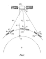
- FIG. 1 there is shown a node spacecraft GEO in geostationary orbit above the earth 10 with low earth orbit user spacecraft LEO1 to LEO n , and it is desired to provide simultaneous optical communication between the node spacecraft GEO and two or more of the user spacecraft LEO1to LEO n , as indicated by communications links 121 to 12 n .
- the node spacecraft communicates with a ground station GS by means of a microwave communications link 14.
- the microwave link 14 is of generally conventional design and its nature and operation will not therefore be described in detail.
- the node spacecraft GEO and the user spacecraft LEO1 to LEO n are provided with complementary optical communications sets 16,181 to 18 n respectively.
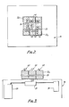
- the optical communications set 16 provided on the node spacecraft GEO is illustrated in outline in Figures 2 and 3.
- the set 16 comprises an optical bench 20 which supports eight terminal heads 221 to 22 n (one for each user spacecraft LEO1 to LEO n ) arranged in a 3x3 rectangular array with a beacon unit 24 and a three-axis set 26 of inertial angular detection sensors secured to the optical bench 20 at the centre of the array.
- the optical bench 20 provides a rigid reference for the terminal heads and the beacon unit to make them substantially immune to any flexing experienced by the node spacecraft.
- the optical bench is capable of limited damped movement with respect to the mode spacecraft.
- the electronics subsystems are distributed within the spacecraft as shown at 28.
- the beacon unit 24 comprises a high power laser source unit 30 which supplies laser radiation to a combiner 32 which supplies the radiation to a collimator 34 in this example via a fibre optic link 36.
- the beam passes from the collimator to a two axis beam pointing assembly 38. It is preferred that only the collimator 34 and the beam pointing assembly be mounted on the optical bench 20.
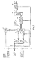
- each node terminal head 22 is arranged to transmit and receive an optical communications beam to and from a user terminal head.
- Each terminal head 22 includes an outer pointing mechanism 40 of periscope form capable of deflecting the beam passed thereby by ⁇ 10° about each of two axes.
- a beam entering the terminal head 22 via the outer pointing mechanism passes to a telescope assembly 44 thence to the inner pointing mechanism 46 which, due to the presence of the telescope assembly 44 has an effective angular range in this example of ⁇ 2° about two angular axes.
- an incoming beam passes via a quarter wave plate 48 to a spectral isolator 50.
- the ATSDU 52 typically includes an acquisition sensor of relatively wide field of view and a tracking sensor of narrower field of view. Data from the acquisition sensor is processed during an acquisition phase to determine the direction of arrival of an incoming beam (a communications beam or an acquisition beam) to provide data for the system control unit to drive the outer pointing mechanism 40 in the direction of the incoming beam. Thereafter, data from the tracking sensor is used to control the inner pointing mechanism 46, and occasionally the outer pointing mechanism 40, to track movement of the incoming beam.
- an incoming beam a communications beam or an acquisition beam
- the remainder of an incoming beam passes from the spectral isolator 50 to a receiver front end unit 54 where the communications signal is demodulated and processed as required.
- the transmission beam is generated at a laser diode package 56 whence it passes to a point ahead assembly 58.
- the point ahead assembly 58 deflects the transmit beam relative to the received beam by an amount to compensate relative movements of the two spacecraft during the time taken for the light to travel between the two spacecraft.
- This assembly is capable of deflecting the beam about two axes and may be of similar construction to the outer pointing mechanism 40 and the inner pointing mechanism 46.
- Control data for the point ahead assembly is supplied by the system control unit.
- the transmission beam passes to the spectral isolator 50 thence to the telescope assembly 44 via the quarter wave plate 48 and the inner pointing mechanism 46. Thereafter the transmission beam passes through the outer pointing mechanism 40 to leave the terminal. It will be understood that the function of the inner and outer pointing mechanisms 46 and 40 is the same for both the incoming and transmission (outgoing)beams namely to align the terminal with the line of sight connecting the terminal to a remote terminal with which data is to be exchanged.
- Each user spacecraft LEO1 to LEO n has a single terminal head 22 of the type illustrated in Figure 5 controlled by a system control unit on board the spacecraft in accordance with data generated on board the spacecraft or provided from a remote spacecraft or ground station.
- the node spacecraft GEO has one terminal head 22 of the type illustrated in Figure 5 for each possible user spacecraft (in this example eight terminal heads), and a single beacon unit 24.
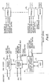
- the control system 60 for controlling the beacon unit 24 and the terminal heads 22 on board the node spacecraft GEO is illustrated in Figure 6.
- the system control unit 62 performs all telecommand operations, power supply conditioning and switching and assembly of the telemetry data.
- the unit 62 interfaces with the spacecraft data handling bus and power sub systems.
- the telecommunications electronics 64 interfaces with the inter-satellite feeder link and performs any coding, digital modulation and signal processing functions.
- the control law and pointing mechanisms electronics unit 66 performs all the necessary computation and control signal processing and generation for the pointing and tracking systems.
- Information on the node spacecraft position and attitude and on the user spacecraft location will be passed to the unit 66 via the system control unit 62. Point ahead look-up information will also be downloaded to the unit 66.
- Unit 66 will also calculate the required control signals for controlling pointing and scanning of the beacon beam emitted by the beacon unit 24.
- Sensor information from the inertial attitude detection system 26 and the acquisition and tracking sensor and drive unit 52 from each terminal head 221 to 22 n is also received and processed by the control law and pointing mechanism control electronics unit 66.
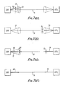
- a typical acquisition sequence for establishing communication between the node spacecraft GEO and a selected user spacecraft LEO1 will be described with reference to Figures 7a to 7d.
- the information on the node spacecraft GEO attitude and position is determined (possibly from information determined or calculated at the ground station GS and supplied by the microwave communications link) and supplied to the control law and pointing mechanism control electronics unit 66, together with information concerning the selected user spacecraft which is gathered in a similar manner.
- the unit 66 calculates the heading of the selected user spacecraft LEO1 with respect to the node spacecraft GEO and determines the point ahead angle to be applied by the point ahead assembly 58 in the selected terminal head 22.
- the unit 66 also calculates a cone of uncertainty centred on the calculated heading, the angle of maximum deflection or the half angle of the cone (herein referred to as the extent of the scan pattern) being selected in accordance with the attitude uncertainty of the node spacecraft, so that if the beacon is scanned through the cone of uncertainty, it will illuminate the selected user at some point in the scan pattern.
- the unit 66 causes the beacon unit to direct a beacon beam 70 of beamwidth B B to follow a scan pattern in the cone of uncertainty 72 centred on the line of sight 76 between the node spacecraft and the user spacecraft.
- the unit 66 also causes the pointing mechanisms of the selected terminal head 221 to follow the pattern of the beacon beam to watch for a return signal from the selected user spacecraft LEO1, until such time as a return signal is received from the selected user spacecraft. This sequence is illustrated in Figure 7a.
- the sensor on the terminal head 221 on the selected user spacecraft LEO1 has a field of view at least as large as the uncertainty cone of the spacecraft and when the sensor detects the incidence of the beacon beam from the beacon 24 by means of the acquisition and tracking sensor and drive unit 52, the unit will track the detected signal and the control unit on the user spacecraft LEO1 will cause the terminal head 221 to point a communications beam 78 of beamwidth B C back up the line of sight 76 to the node spacecraft GEO. This is illustrated in Figure 7b. (B C is much less than B B ).
- the incidence of the communications beam 78 on the terminal head 221 readies the node spacecraft GEO.
- the node spacecraft then begins to track the communications beam 78 and switches on its narrow communications beam and directs it along the line of sight 76.
- the beacon beam is no longer required for this particular acquisition sequence. This is illustrated in Figure 7c.
- the communications beam from the node spacecraft GEO reaches the user spacecraft LEO1 and the link is established (Figure 7d).
- Relative movement of the spacecraft is detected by the acquisition and tracking sensor and drive units 52 in the terminal head 22, on the node spacecraft GEO and the terminal head 22 on the user spacecraft LEO1 which effect any adjustments to the pointing mechanisms that are required to maintain the communications link.
- the initial stage of the acquisition phase is achieved using a single beacon unit which may be pointed independently from each of the terminal heads. If conventional techniques were used, one beacon unit would be needed for each terminal unit and hence there is a weight saving of N-1 times the beacon weight where N is the number of user spacecraft. There will of course need to be an independent pointing mechanism for the beacon, but this will weigh considerably less than N-1 times the beacon weight and so the present arrangement provides a considerable reduction in overall weight of the optical communications system.
- the illustrated communication system is configured to implement a method which considerably reduces the acquisition time for acquiring second and subsequent user spacecraft. In essence this reduction is achieved by reducing the extent of the uncertainty cone associated with the node spacecraft so that the scanning time is reduced.
- the positions of the node spacecraft and the user spacecraft may be determined with a sufficient degree of accuracy, for example from data supported by the ground station GS.
- the attitudes of the various spacecraft at these positions are not known with a sufficiently high degree of accuracy (i.e. having regard to the beam width of the optical communications beams to be passed between the spacecraft and the separation of the spacecraft).
- the attitude error may be resolved into translations along the X and Y axes and a rotation about the Z axis.
- the control law and pointing mechanism control electronics unit 66 stores data representing the half angle of the cone of uncertainty and, possibly, its disposition relative to the node spacecraft. When the first user spacecraft LEO1 has been acquired this provides an attitude "fix" which is used by the control law and pointing mechanism control electronics unit 66 to refine the cone of uncertainty to reduce its angular extent. Data representing the revised cone of uncertainty is stored by the unit 66. In effect, by acquiring the first user the error in the X and Y axes discussed above is much reduced but the rotation error about Z is not known. It will be appreciated that this refinement occurs because once the first acquisition has been made, the system has, in addition to accurate data representing the positions of the spacecraft relative to earth, a very accurate reading of the heading of the user spacecraft relative to the node spacecraft.
- the reduction in the cone of uncertainty means that the time taken for the beacon to sweep through the uncertainty cone is reduced.
- the time for the first acquisition would be 30 seconds and that for the second 10 seconds. (These values are on the basis that the tracking routine disclosed in our earlier European Patent Application No. 88311009.0 is employed).
- the cone of uncertainty that needs to be scanned in the second acquisition is reduced to that needed to cover "rotational" error about the axis of the previous acquisition squence.
Abstract
Description
- This invention relates to a multiple access communication system in which a "node" communication station may communicate with two or more "user" communication stations. In particular, but not exclusively, the invention relates to multiple access optical communication systems for use on a spacecraft. The invention may extend to very high frequency radio systems. In addition the system may provide communications between other communication stations such as aircraft.
- There is considerable interest in providing an optical communication system to allow large amounts of data to be transmitted between spacecraft. In many applications data needs to be transmitted simultaneously from one spacecraft (perhaps in geostationary orbit) to a plurality of other spacecraft (perhaps in a plurality of low earth orbits). Similarly it may be required to transmit data from several low earth orbin spacecraft simultaneously to a single geostationary orbit spacecraft. Examples of such systems include those for gathering weather data or earth resource data. In addition, of course it is commonly desired to transmit data between two geostationary orbit spacecraft.
- There is thus a need for a communications system which allows simultaneous communication between a node spacecraft and several user spacecraft. Where communication is via an optical beam it is important to point the communications beam accurately along the line of sight connecting the node spacecraft and the relevant user spacecraft because the beam width of the optical communications beam is very narrow. This precise pointing requirement means that the node spacecraft and the user spacecraft must each have accurately pointable transmit/receive terminals together with some means which allows the node and user spacecraft to acquire and track each other.
- It has been proposed to provide an optical communications system which allows two-way data exchange between one spacecraft carrying an appropriate set of communication apparatus to one, and only one, spacecraft carrying a matching set of apparatus. Briefly each set of apparatus on the node spacecraft includes a pointable transmit/receive terminal which incorporates an acquisition beacon, acquisition and tracking sensors, transmit/receive equipment including associated multiplexing and demultiplexing devices and a terminal control. If simultaneous optical communication is required with more than one user spacecraft then the node spacecraft needs to carry one set of communications apparatus for each user spacecraft. However, this arrangement will have a heavy weight penalty. The Applicants have designed a system which will allow simultaneous optical communication between a node spacecraft and several user spacecraft in which the communications equipment is of reduced weight compared to the above proposal.
- According to one aspect of this invention there is provided a communication system, comprising a plurality of user stations each having a transmit/receive terminal, a node station having a plurality of transmit/receive terminals associated with respective ones of said user stations, and beacon beam means provided at said node station for initiating respective acquisition phases for linking respective ones of said transmit/receive terminals on said node station with the transmit/receive terminal on the corresponding user station, and means for providing a rigid reference at said node station for the associated transmit/receive terminals and said beacon beam means.
- Another factor encountered in optical communications systems is the acquisition time taken for the node spacecraft and a user spacecraft to establish communication. The acquisition time (in conventional systems about 1 ½ to 2 minutes) represents "lost" communications time and is particularly significant in communications between a geostationary orbit spacecraft and a low earth orbit spacecraft where the low earth orbit spacecraft may be in the field of view of the geostationary orbit spacecraft for only an hour or so for each orbit. It is thus highly desirable to minimise the acquisition time. A large proportion of the acquisition time is spent in scanning a beacon on the node spacecraft through an uncertainty cone within which the user spacecraft is expected to lie. The uncertainty cone exists because, although it is possible to locate the relative positions of the spacecraft with sufficient accuracy, the angular attitude of the node spacecraft cannot usually be maintained better than about 0.2° in roll pitch and yaw. Thus, even though the theoretical line of sight connecting the node spacecraft and the user spacecraft can be determined with high accuracy the beacon must perform a scan pattern around this line of sight, with the extent or magnitude of maximum angular deviation from the line of sight being determined by the magnitude of the node spacecraft's attitude uncertainty. In our earlier European Patent Application No. 88311009.0, the contents of which are incorporated herein by reference, we disclosed a modified scanning method by which the scanning pattern of the beacon and that of the acquisition sensor on the node spacecraft may be performed to reduce the acquisition time to about 30 seconds. We have found that the acquisition time may be reduced further in a multi-user system by using the first "fix" obtained when the first user is acquired to refine or reduce the attitude uncertainty of the node spacecraft so that when acquiring the second user spacecraft, the extent of this scan pattern may be reduced so reducing the acquisition time for the second user spacecraft. By using the second "fix" the attitude uncertainty can be further refined so that for third and subsequent acquisitions a further reduced scan pattern can be used, with a consequent reduction in time. It is believed that if two attitude fixes are obtained within a short time frame the scan pattern may be optimised and thus there will not normally be a further reduction in acquisition time for fourth and subsequent acquisitions. It should be noted that the acquisition time reduction method may be used either in conjunction with the reduction method described in our earlier European Patent Application No. 88311009.0 or separately.
- According to another aspect of the invention, there is provided, in a system including a node station and at least two user stations, wherein the relative positions of the node station and user stations may be determined and wherein the angular attitude of the node stations relative to a reference frame may be estimated subject to an uncertainty factor, a method of establishing communications between said node station and each of said user stations, which comprises causing an acquisition beam associated with said node station to follow a first scan pattern about an axis connecting it to a selected one user station, the pattern being of extent dependent on said uncertainty factor, causing said one user station to transmit a beam back to said node station whereby the estimate of the angular attitude of the node station may be refined, and thereafter causing said acquisition beam to follow a second scan mode about an axis connecting said node station with another of said user stations, the pattern being of correspondingly reduced extent.
- The invention will now be described by way of example only, reference being made to the accompanying drawings, in which:-
- Figure 1 is a schematic view showing a node spacecraft in geostationary orbit and a plurality of user spacecraft in low earth orbit;
- Figure 2 is a view on a wall of the node spacecraft showing an optical bench supporting a beacon unit and eight terminal heads;
- Figure 3 is a side view on the arrangement of Figure 2;
- Figure 4 is a schematic diagram illustrating the beacon unit used on the node spacecraft;
- Figure 5 is a schematic block diagram illustrating one of the terminal heads as used on the node spacecraft and each user spacecraft;
- Figure 6 is a functional system diagram illustrating the control system for controlling operation of the terminal heads and the beacon unit on the node spacecraft, and
- Figures 7a to 7d illustrate the acquisition sequence for establishing communication between the node spacecraft and the user spacecraft.
- Referring to Figure 1 there is shown a node spacecraft GEO in geostationary orbit above the
earth 10 with low earth orbit user spacecraft LEO₁ to LEOn, and it is desired to provide simultaneous optical communication between the node spacecraft GEO and two or more of the user spacecraft LEO₁to LEOn, as indicated bycommunications links 12₁ to 12n. The node spacecraft communicates with a ground station GS by means of amicrowave communications link 14. - The
microwave link 14 is of generally conventional design and its nature and operation will not therefore be described in detail. - The node spacecraft GEO and the user spacecraft LEO₁ to LEOn, are provided with complementary
optical communications sets set 16 comprises anoptical bench 20 which supports eightterminal heads 22₁ to 22n (one for each user spacecraft LEO₁ to LEOn) arranged in a 3x3 rectangular array with abeacon unit 24 and a three-axis set 26 of inertial angular detection sensors secured to theoptical bench 20 at the centre of the array. Theoptical bench 20 provides a rigid reference for the terminal heads and the beacon unit to make them substantially immune to any flexing experienced by the node spacecraft. Indeed, in one example, the optical bench is capable of limited damped movement with respect to the mode spacecraft.The electronics subsystems are distributed within the spacecraft as shown at 28. Referring to Figure 4 thebeacon unit 24 comprises a high powerlaser source unit 30 which supplies laser radiation to acombiner 32 which supplies the radiation to acollimator 34 in this example via a fibreoptic link 36. The beam passes from the collimator to a two axisbeam pointing assembly 38. It is preferred that only thecollimator 34 and the beam pointing assembly be mounted on theoptical bench 20. - Referring now to Figure 5 each node terminal head 22 is arranged to transmit and receive an optical communications beam to and from a user terminal head. Each terminal head 22 includes an
outer pointing mechanism 40 of periscope form capable of deflecting the beam passed thereby by ±10° about each of two axes. A beam entering the terminal head 22 via the outer pointing mechanism passes to atelescope assembly 44 thence to theinner pointing mechanism 46 which, due to the presence of thetelescope assembly 44 has an effective angular range in this example of ±2° about two angular axes. From theinner pointing mechanism 46, an incoming beam passes via aquarter wave plate 48 to aspectral isolator 50. Here a small portion of the incoming beam is stripped off to pass to an acquisition and tracking sensor and drive unit (ATSDU) 52. The ATSDU 52 typically includes an acquisition sensor of relatively wide field of view and a tracking sensor of narrower field of view. Data from the acquisition sensor is processed during an acquisition phase to determine the direction of arrival of an incoming beam (a communications beam or an acquisition beam) to provide data for the system control unit to drive theouter pointing mechanism 40 in the direction of the incoming beam. Thereafter, data from the tracking sensor is used to control theinner pointing mechanism 46, and occasionally theouter pointing mechanism 40, to track movement of the incoming beam. - The remainder of an incoming beam passes from the
spectral isolator 50 to a receiverfront end unit 54 where the communications signal is demodulated and processed as required. - The transmission beam is generated at a
laser diode package 56 whence it passes to a point aheadassembly 58. The point aheadassembly 58 deflects the transmit beam relative to the received beam by an amount to compensate relative movements of the two spacecraft during the time taken for the light to travel between the two spacecraft. This assembly is capable of deflecting the beam about two axes and may be of similar construction to theouter pointing mechanism 40 and theinner pointing mechanism 46. Control data for the point ahead assembly is supplied by the system control unit. - From the point ahead
assembly 58, the transmission beam passes to thespectral isolator 50 thence to thetelescope assembly 44 via thequarter wave plate 48 and theinner pointing mechanism 46. Thereafter the transmission beam passes through theouter pointing mechanism 40 to leave the terminal. It will be understood that the function of the inner andouter pointing mechanisms - In practice, each terminal will of coure have back up equipment where necessary; for simplicity such equipment has been omitted from the drawings.
- Each user spacecraft LEO₁ to LEOn has a single terminal head 22 of the type illustrated in Figure 5 controlled by a system control unit on board the spacecraft in accordance with data generated on board the spacecraft or provided from a remote spacecraft or ground station.
- The node spacecraft GEO has one terminal head 22 of the type illustrated in Figure 5 for each possible user spacecraft (in this example eight terminal heads), and a
single beacon unit 24. The control system 60 for controlling thebeacon unit 24 and the terminal heads 22 on board the node spacecraft GEO is illustrated in Figure 6. - The
system control unit 62 performs all telecommand operations, power supply conditioning and switching and assembly of the telemetry data. Theunit 62 interfaces with the spacecraft data handling bus and power sub systems. Thetelecommunications electronics 64 interfaces with the inter-satellite feeder link and performs any coding, digital modulation and signal processing functions. The control law and pointingmechanisms electronics unit 66 performs all the necessary computation and control signal processing and generation for the pointing and tracking systems. Information on the node spacecraft position and attitude and on the user spacecraft location will be passed to theunit 66 via thesystem control unit 62. Point ahead look-up information will also be downloaded to theunit 66.Unit 66 will also calculate the required control signals for controlling pointing and scanning of the beacon beam emitted by thebeacon unit 24. Sensor information from the inertialattitude detection system 26 and the acquisition and tracking sensor and driveunit 52 from eachterminal head 22₁ to 22n is also received and processed by the control law and pointing mechanismcontrol electronics unit 66. - A typical acquisition sequence for establishing communication between the node spacecraft GEO and a selected user spacecraft LEO₁ will be described with reference to Figures 7a to 7d. Firstly, the information on the node spacecraft GEO attitude and position is determined (possibly from information determined or calculated at the ground station GS and supplied by the microwave communications link) and supplied to the control law and pointing mechanism
control electronics unit 66, together with information concerning the selected user spacecraft which is gathered in a similar manner. Theunit 66 then calculates the heading of the selected user spacecraft LEO₁ with respect to the node spacecraft GEO and determines the point ahead angle to be applied by the point ahead assembly 58 in the selected terminal head 22. Theunit 66 also calculates a cone of uncertainty centred on the calculated heading, the angle of maximum deflection or the half angle of the cone (herein referred to as the extent of the scan pattern) being selected in accordance with the attitude uncertainty of the node spacecraft, so that if the beacon is scanned through the cone of uncertainty, it will illuminate the selected user at some point in the scan pattern. Theunit 66 causes the beacon unit to direct abeacon beam 70 of beamwidth BB to follow a scan pattern in the cone ofuncertainty 72 centred on the line ofsight 76 between the node spacecraft and the user spacecraft. Theunit 66 also causes the pointing mechanisms of the selectedterminal head 22₁ to follow the pattern of the beacon beam to watch for a return signal from the selected user spacecraft LEO₁, until such time as a return signal is received from the selected user spacecraft. This sequence is illustrated in Figure 7a. - The sensor on the
terminal head 22₁ on the selected user spacecraft LEO₁ has a field of view at least as large as the uncertainty cone of the spacecraft and when the sensor detects the incidence of the beacon beam from thebeacon 24 by means of the acquisition and tracking sensor and driveunit 52, the unit will track the detected signal and the control unit on the user spacecraft LEO₁ will cause theterminal head 22₁ to point acommunications beam 78 of beamwidth BC back up the line ofsight 76 to the node spacecraft GEO. This is illustrated in Figure 7b. (BC is much less than BB). - The incidence of the
communications beam 78 on theterminal head 22₁ readies the node spacecraft GEO. The node spacecraft then begins to track thecommunications beam 78 and switches on its narrow communications beam and directs it along the line ofsight 76. The beacon beam is no longer required for this particular acquisition sequence. This is illustrated in Figure 7c. - Finally, the communications beam from the node spacecraft GEO reaches the user spacecraft LEO₁ and the link is established (Figure 7d). Relative movement of the spacecraft is detected by the acquisition and tracking sensor and drive
units 52 in the terminal head 22, on the node spacecraft GEO and the terminal head 22 on the user spacecraft LEO₁ which effect any adjustments to the pointing mechanisms that are required to maintain the communications link. - The establishment of communication with subsequent user spacecraft follows the sequence described above escept that the scan pattern is preferably modified as to be described below.
- In this arrangement, it will be appreciated that the initial stage of the acquisition phase is achieved using a single beacon unit which may be pointed independently from each of the terminal heads. If conventional techniques were used, one beacon unit would be needed for each terminal unit and hence there is a weight saving of N-1 times the beacon weight where N is the number of user spacecraft. There will of course need to be an independent pointing mechanism for the beacon, but this will weigh considerably less than N-1 times the beacon weight and so the present arrangement provides a considerable reduction in overall weight of the optical communications system.
- One consequence of employing a single beacon is that, if several user spacecraft need to be acquired in the same period, it will be necessary to perform the acquisition phases sequentially rather than in parallel. Thus, any reduction in acquisition time represents a significant benefit.
- The illustrated communication system is configured to implement a method which considerably reduces the acquisition time for acquiring second and subsequent user spacecraft. In essence this reduction is achieved by reducing the extent of the uncertainty cone associated with the node spacecraft so that the scanning time is reduced.
- Before any links have been acquired, the positions of the node spacecraft and the user spacecraft may be determined with a sufficient degree of accuracy, for example from data supported by the ground station GS. However, the attitudes of the various spacecraft at these positions are not known with a sufficiently high degree of accuracy (i.e. having regard to the beam width of the optical communications beams to be passed between the spacecraft and the separation of the spacecraft). If an orthogonal set of coordinate axes X,Y and Z is defined with the Z axis pointing down the line of sight, then the attitude error may be resolved into translations along the X and Y axes and a rotation about the Z axis. The control law and pointing mechanism
control electronics unit 66 stores data representing the half angle of the cone of uncertainty and, possibly, its disposition relative to the node spacecraft. When the first user spacecraft LEO₁ has been acquired this provides an attitude "fix" which is used by the control law and pointing mechanismcontrol electronics unit 66 to refine the cone of uncertainty to reduce its angular extent. Data representing the revised cone of uncertainty is stored by theunit 66. In effect, by acquiring the first user the error in the X and Y axes discussed above is much reduced but the rotation error about Z is not known. It will be appreciated that this refinement occurs because once the first acquisition has been made, the system has, in addition to accurate data representing the positions of the spacecraft relative to earth, a very accurate reading of the heading of the user spacecraft relative to the node spacecraft. - The reduction in the cone of uncertainty means that the time taken for the beacon to sweep through the uncertainty cone is reduced. In a typical example, the time for the first acquisition would be 30 seconds and that for the second 10 seconds. (These values are on the basis that the tracking routine disclosed in our earlier European Patent Application No. 88311009.0 is employed). In effect, the cone of uncertainty that needs to be scanned in the second acquisition is reduced to that needed to cover "rotational" error about the axis of the previous acquisition squence.
- Once the second user has been acquired however, this rotational error can be resolved as the relative orientation of the lines of sight connecting the mode spacecraft to the first and second user spacecraft is known. The required scan for the acquisition of the third (and subsequent) user spacecraft need now only be that the error angle induced by computational calculations, and mechanical tolerances of the equipment. In some applications the area to be covered may well be within the beam width of the beacon beams so that no scanning is necessary. It must be understood that as long as the node spacecraft is optically linked to two user spacecraft whose positions are known, the attitude of the optical bench (and thus all the terminal heads and the beacon view associated therewith) may be calculated absolutely, subject to errors due to computational calculations and mechanical tolerances.
- Examples of appropriate structures for the outer pointing, point ahead and
inner pointing mechanisms
Claims (10)
a plurality of steerable node transmit/receive terminals at said node station for transmitting or receiving a relatively narrow communications beam to or from a respective user station;
a steerable beacon means at said node station for emitting a relatively broad acquisition beam to illuminate any one of said user stations;
acquisition control means operable during an acquisition phase for controlling said beacon means and one of said node transmit/receive terminals to follow related scan patterns, and
a steerable user transmit/receive terminal provided at each user station for transmitting or receiving a relatively narrow communications beam to or from a transmit/receive terminal at said node station, and each of said user transmit/receive terminals being responsive to illumination by said beacon means to transmit a communications beam to said node station.
Applications Claiming Priority (2)
| Application Number | Priority Date | Filing Date | Title |
|---|---|---|---|
| GB888801008A GB8801008D0 (en) | 1988-01-18 | 1988-01-18 | Acquisition system for multiple access optical communication system |
| GB8801008 | 1988-01-18 |
Publications (3)
| Publication Number | Publication Date |
|---|---|
| EP0325429A2 true EP0325429A2 (en) | 1989-07-26 |
| EP0325429A3 EP0325429A3 (en) | 1991-01-02 |
| EP0325429B1 EP0325429B1 (en) | 1994-10-26 |
Family
ID=10630114
Family Applications (1)
| Application Number | Title | Priority Date | Filing Date |
|---|---|---|---|
| EP89300447A Expired - Lifetime EP0325429B1 (en) | 1988-01-18 | 1989-01-18 | Multiple access communication system |
Country Status (5)
| Country | Link |
|---|---|
| US (1) | US5119225A (en) |
| EP (1) | EP0325429B1 (en) |
| AT (1) | ATE113427T1 (en) |
| DE (1) | DE68918959T2 (en) |
| GB (1) | GB8801008D0 (en) |
Cited By (24)
| Publication number | Priority date | Publication date | Assignee | Title |
|---|---|---|---|---|
| DE3940041A1 (en) * | 1989-12-04 | 1991-06-06 | Messerschmitt Boelkow Blohm | Earth orbit satellite system - has number of sensor and control units coupled to on-board satellite unit |
| US5142400A (en) * | 1989-12-26 | 1992-08-25 | Cubic Corporation | Method and apparatus for automatic acquisition and alignment of an optical beam communication link |
| EP0504022A1 (en) * | 1991-03-15 | 1992-09-16 | Thomson-Csf | Optical communication system between mobile stations and corresponding communication method |
| WO1992022150A1 (en) * | 1991-06-04 | 1992-12-10 | Agence Spatiale Europeenne | Optical communications terminal |
| FR2691310A1 (en) * | 1992-05-12 | 1993-11-19 | Alsthom Cge Alcatel | Optical link device for mobile, in particular for earth satellite. |
| DE4313945A1 (en) * | 1993-04-28 | 1994-11-03 | Diehl Gmbh & Co | Method and devices for disseminating standard time information |
| DE4324515A1 (en) * | 1993-07-21 | 1995-01-26 | Kayser Threde Gmbh | Method and device for extending the communication duration of spacecraft |
| WO1996024199A1 (en) * | 1995-02-02 | 1996-08-08 | Alcatel Espace | Personal communications via low-orbiting moving and geostationary satellites |
| EP0767547A2 (en) * | 1995-10-03 | 1997-04-09 | Trw Inc. | Multiple altitude satellite relay system and method |
| EP0788246A2 (en) * | 1996-02-05 | 1997-08-06 | HE HOLDINGS, INC. dba HUGHES ELECTRONICS | Geosynchronous hub communications satelite and system |
| GB2319700A (en) * | 1996-11-25 | 1998-05-27 | Motorola Inc | Satellite communication system using satellites at different altitudes |
| EP0845876A2 (en) * | 1996-11-27 | 1998-06-03 | Trw Inc. | Multiple altitude satellite relay system and method |
| FR2756992A1 (en) * | 1996-12-05 | 1998-06-12 | Motorola Inc | HYBRID CONSTELLATION SATELLITE COMMUNICATION SYSTEM AND METHOD WITH EFFICIENT SIGNALING AND CONTROL |
| EP0849890A2 (en) * | 1996-12-19 | 1998-06-24 | Globalstar L.P. | Satellite low orbital communication system with connection through earth gateway |
| FR2761216A1 (en) * | 1997-03-24 | 1998-09-25 | Matra Marconi Space France | Optical telecommunications terminal for light signals modulated by communication signals |
| EP0883253A1 (en) * | 1997-10-01 | 1998-12-09 | Oerlikon Contraves Ag | Method and apparatus for optimizing optical intersatellite connections |
| WO1998057446A1 (en) * | 1997-06-12 | 1998-12-17 | Motorola, Inc. | Multi-tier satellite system and method of operation |
| EP0949143A3 (en) * | 1998-04-10 | 2000-02-23 | Laser Communications International, L.L.C. | Method and apparatus for improved attitude determination of spacecraft |
| EP1130809A2 (en) * | 2000-01-13 | 2001-09-05 | TRW Inc. | Satellite optical communication acquisition techniques |
| WO2002075964A1 (en) * | 2001-03-15 | 2002-09-26 | Adzhalov Vladimir Isfandeyarov | Access method for data packet networks |
| EP1777844A1 (en) * | 2005-10-24 | 2007-04-25 | Astrium Sas | Communication system by multiuser optical link, multiuser terminal and communication method therefor |
| WO2009070340A1 (en) * | 2007-11-30 | 2009-06-04 | Raytheon Company | Space-time division multiple-access laser communications system |
| EP2873172B1 (en) * | 2012-07-13 | 2020-02-19 | Raytheon Company | High-bandwidth optical communications relay architecture |
| EP3806351A1 (en) * | 2019-10-11 | 2021-04-14 | Nederlandse Organisatie voor toegepast- natuurwetenschappelijk Onderzoek TNO | Optimizing alignment in optical communication |
Families Citing this family (94)
| Publication number | Priority date | Publication date | Assignee | Title |
|---|---|---|---|---|
| US5303286A (en) * | 1991-03-29 | 1994-04-12 | Space Systems/Loral, Inc. | Wireless telephone/satellite roaming system |
| US5433726A (en) * | 1991-04-22 | 1995-07-18 | Trw Inc. | Medium-earth-altitude satellite-based cellular telecommunications system |
| US5439190A (en) * | 1991-04-22 | 1995-08-08 | Trw Inc. | Medium-earth-altitude satellite-based cellular telecommunications |
| CA2078932C (en) * | 1991-10-10 | 2003-12-02 | Robert A. Wiedeman | Satellite telecommunications system using network coordinating gateways operative with a terrestrial communication system |
| US5526404A (en) * | 1991-10-10 | 1996-06-11 | Space Systems/Loral, Inc. | Worldwide satellite telephone system and a network coordinating gateway for allocating satellite and terrestrial gateway resources |
| EP0541052B1 (en) * | 1991-11-05 | 1996-02-07 | Hitachi, Ltd. | Spacecraft system |
| US5710652A (en) * | 1992-08-27 | 1998-01-20 | Trex Communications | Laser communication transceiver and system |
| FR2696890B1 (en) * | 1992-10-08 | 1994-11-04 | Alcatel Espace | Data transmission system in a satellite. |
| US5422647A (en) * | 1993-05-07 | 1995-06-06 | Space Systems/Loral, Inc. | Mobile communication satellite payload |
| TW239242B (en) * | 1994-03-28 | 1995-01-21 | Leo One Ip L L C | Satellite system using equatorial & polar orbit relays |
| US5859874A (en) * | 1994-05-09 | 1999-01-12 | Globalstar L.P. | Multipath communication system optimizer |
| US6400926B1 (en) * | 1994-06-22 | 2002-06-04 | Ericsson Ge Mobile Communications Inc. | Radiocommunication system using geostationary and non-geostationary satellites |
| US5475520A (en) * | 1994-06-22 | 1995-12-12 | Hughes Aircraft Company | Satellite communications system |
| US5566354A (en) * | 1994-09-26 | 1996-10-15 | Sehloemer; Jerry R. | System and method for channel assignment in a satellite telephone system |
| JP2639359B2 (en) * | 1994-10-31 | 1997-08-13 | 日本電気株式会社 | Transmitter for non-geostationary satellite |
| US5787336A (en) * | 1994-11-08 | 1998-07-28 | Space Systems/Loral, Inc. | Satellite communication power management system |
| US5592481A (en) * | 1995-06-06 | 1997-01-07 | Globalstar L.P. | Multiple satellite repeater capacity loading with multiple spread spectrum gateway antennas |
| US5619525A (en) * | 1995-06-06 | 1997-04-08 | Globalstar L.P. | Closed loop power control for low earth orbit satellite communications system |
| BR9608410A (en) | 1995-06-06 | 1998-12-29 | Globalstar Lp | Repeater satellite diversity resource management system |
| US5634190A (en) * | 1995-06-06 | 1997-05-27 | Globalstar L.P. | Low earth orbit communication satellite gateway-to-gateway relay system |
| US5640386A (en) * | 1995-06-06 | 1997-06-17 | Globalstar L.P. | Two-system protocol conversion transceiver repeater |
| US6240124B1 (en) | 1995-06-06 | 2001-05-29 | Globalstar L.P. | Closed loop power control for low earth orbit satellite communications system |
| US5664006A (en) * | 1995-06-07 | 1997-09-02 | Globalstar L.P. | Method for accounting for user terminal connection to a satellite communications system |
| US5552920A (en) * | 1995-06-07 | 1996-09-03 | Glynn; Thomas W. | Optically crosslinked communication system (OCCS) |
| US5802445A (en) * | 1995-07-13 | 1998-09-01 | Globalstar L.P. | Methods and apparatus for providing user RF exposure monitoring and control in a satellite communications system |
| US6272325B1 (en) | 1995-07-13 | 2001-08-07 | Globalstar L.P. | Method and apparatus for considering user terminal transmitted power during operation in a plurality of different communication systems |
| US5758260A (en) * | 1995-08-23 | 1998-05-26 | Globalstar L.P. | Satellite beam steering reference using terrestrial beam steering terminals |
| US6272316B1 (en) | 1995-11-17 | 2001-08-07 | Globalstar L.P. | Mobile satellite user information request system and methods |
| US5812932A (en) * | 1995-11-17 | 1998-09-22 | Globalstar L.P. | Mobile satellite user information request system and methods |
| US5833175A (en) * | 1995-12-22 | 1998-11-10 | Hughes Electronics Corporation | Spacecraft with large east-west dimensions |
| US6072768A (en) | 1996-09-04 | 2000-06-06 | Globalstar L.P. | Automatic satellite/terrestrial mobile terminal roaming system and method |
| US6201961B1 (en) | 1996-09-13 | 2001-03-13 | Globalstar L. P. | Use of reference phone in point-to-point satellite communication system |
| US6587687B1 (en) | 1996-10-21 | 2003-07-01 | Globalstar L.P. | Multiple satellite fade attenuation control system |
| DE59701839D1 (en) * | 1996-11-15 | 2000-07-13 | Contraves Space Ag Zuerich | Method and arrangement for maintaining the position of a geostationary swarm of satellites using an optical satellite connection |
| US6047161A (en) * | 1996-11-29 | 2000-04-04 | Motorola, Inc. | Satellite communication system and method thereof |
| US5956619A (en) * | 1996-12-12 | 1999-09-21 | Globalstar L.P. | Satellite controlled power control for personal communication user terminals |
| US5875180A (en) * | 1997-02-06 | 1999-02-23 | Globalstar L.P. | Satellite telephone interference avoidance system |
| DE59704657D1 (en) * | 1997-03-07 | 2001-10-25 | Contraves Space Ag Zuerich | Method and arrangement for optical communication via satellites |
| US5918157A (en) * | 1997-03-18 | 1999-06-29 | Globalstar L.P. | Satellite communications system having distributed user assignment and resource assignment with terrestrial gateways |
| US6128487A (en) * | 1997-04-15 | 2000-10-03 | Globalstar, L.P. | Global mobile paging system |
| US6064857A (en) * | 1997-04-15 | 2000-05-16 | Globalstar L.P. | Dual mode satellite telephone with hybrid battery/capacitor power supply |
| US5884142A (en) * | 1997-04-15 | 1999-03-16 | Globalstar L.P. | Low earth orbit distributed gateway communication system |
| US5905943A (en) * | 1997-04-29 | 1999-05-18 | Globalstar L.P. | System for generating and using global radio frequency maps |
| US6021309A (en) * | 1997-05-22 | 2000-02-01 | Globalstar L.P. | Channel frequency allocation for multiple-satellite communication network |
| US6019318A (en) * | 1997-06-16 | 2000-02-01 | Hugehs Electronics Corporation | Coordinatable system of inclined geosynchronous satellite orbits |
| US6081710A (en) * | 1997-07-10 | 2000-06-27 | Globalstar L.P. | Dynamic traffic allocation for power control in multiple satellite communication systems |
| US6101385A (en) * | 1997-10-09 | 2000-08-08 | Globalstar L.P. | Satellite communication service with non-congruent sub-beam coverage |
| US6043918A (en) * | 1997-12-12 | 2000-03-28 | Stanford Telecommunications, Inc. | Laser satellite communication systems |
| US6418147B1 (en) | 1998-01-21 | 2002-07-09 | Globalstar Lp | Multiple vocoder mobile satellite telephone system |
| US6029935A (en) * | 1998-01-22 | 2000-02-29 | Trw Inc. | Method for adding a geostationary component to a non-geostationary satellite network |
| US6816710B2 (en) * | 1998-05-06 | 2004-11-09 | Snaptrack, Inc. | Method and apparatus for signal processing in a satellite positioning system |
| US6195044B1 (en) * | 1998-06-19 | 2001-02-27 | Hughes Electronics Corporation | Laser crosslink satellite attitude determination system and method |
| US6661996B1 (en) | 1998-07-14 | 2003-12-09 | Globalstar L.P. | Satellite communication system providing multi-gateway diversity to a mobile user terminal |
| US6271953B1 (en) * | 1998-09-02 | 2001-08-07 | Harris Corporation | Method and system for optical free space communications using non-mechanical beam steering |
| US5999127A (en) * | 1998-10-06 | 1999-12-07 | The Aerospace Corporation | Satellite communications facilitated by synchronized nodal regressions of low earth orbits |
| US6257526B1 (en) | 1998-11-09 | 2001-07-10 | Hughes Electronics Corporation | Satellite system and method of deploying same |
| US6556808B1 (en) * | 1998-12-30 | 2003-04-29 | The Boeing Company | Fixed ground track satellite constellation and user terminal |
| US6327523B2 (en) | 1999-01-21 | 2001-12-04 | Hughes Electronics Corporation | Overhead system of inclined eccentric geosynchronous orbitting satellites |
| US6912075B1 (en) * | 1999-05-17 | 2005-06-28 | The Directv Group, Inc. | Ring architecture for an optical satellite communication network with passive optical routing |
| US7103280B1 (en) * | 1999-06-05 | 2006-09-05 | The Directv Group, Inc. | Architecture for an optical satellite communication network |
| US6816682B1 (en) * | 1999-06-07 | 2004-11-09 | The Directv Group, Inc. | Global gateway architecture for interconnecting regional satellites into a communication network |
| US6253080B1 (en) | 1999-07-08 | 2001-06-26 | Globalstar L.P. | Low earth orbit distributed gateway communication system |
| US6704543B1 (en) | 1999-09-27 | 2004-03-09 | Ems Technologies, Inc. | Multi-beam satellite communications system |
| US6633744B1 (en) | 1999-10-12 | 2003-10-14 | Ems Technologies, Inc. | Ground-based satellite communications nulling antenna |
| US6463279B1 (en) | 1999-11-17 | 2002-10-08 | Globalstar L.P. | Channel frequency allocation for multiple-satellite communication network |
| US6836658B1 (en) | 2000-03-03 | 2004-12-28 | Ems Technologies, Inc. | High data rate satellite communications system and method |
| US7184761B1 (en) * | 2000-03-27 | 2007-02-27 | The Directv Group, Inc. | Satellite communications system |
| US7369809B1 (en) | 2000-10-30 | 2008-05-06 | The Directv Group, Inc. | System and method for continuous broadcast service from non-geostationary orbits |
| US6510401B2 (en) | 2001-05-11 | 2003-01-21 | The United States Of America As Represented By The Director Of The National Security Agency | Method of authenticating beacon |
| US7389052B2 (en) * | 2002-01-30 | 2008-06-17 | Texas Instruments Incorporated | Calibration method for station orientation |
| US7292788B2 (en) * | 2003-01-31 | 2007-11-06 | Lockheed Martin Corporation | Multi-beam laser communications system and method |
| US7292789B1 (en) * | 2003-04-10 | 2007-11-06 | Lockheed Martin Corporation | Multi-channel wide-field laser communications method and apparatus |
| US7277641B1 (en) | 2003-05-06 | 2007-10-02 | Ball Aerospace & Technologies Corp. | Multiple access space communications optical system using a common telescope aperture |
| US7457545B2 (en) * | 2004-02-12 | 2008-11-25 | Northrop Grumman Corporation | Process for controlling a Hartmann wavefront sensor (WFS) in an adaptive optic (AO) system |
| US7343099B2 (en) * | 2004-02-12 | 2008-03-11 | Metrologic Instruments, Inc. | Free space optical (FSO) laser communication system employing fade mitigation measures based on laser beam speckle tracking and locking principles |
| US7668468B1 (en) | 2004-10-01 | 2010-02-23 | Ball Aerospace & Technologies Corp. | Numerous user laser communications optical system using chromatic waveplates and a common telescope aperture |
| CN1777063B (en) * | 2005-12-16 | 2011-07-27 | 北京大学 | Trapping system for satellite laser communication |
| CN1777064B (en) * | 2005-12-16 | 2011-08-24 | 北京大学 | Satellite laser communication terminal |
| US8300798B1 (en) | 2006-04-03 | 2012-10-30 | Wai Wu | Intelligent communication routing system and method |
| FR2936893B1 (en) * | 2008-10-06 | 2010-11-19 | Astrium Sas | OPTICAL TRANSMIT RECEIVING ASSEMBLY WITH CONTROL OF TRANSMISSION DIRECTION |
| US20100279604A1 (en) * | 2009-05-04 | 2010-11-04 | Cisco Technology, Inc. | Intersatellite Links |
| KR20120071238A (en) * | 2010-12-22 | 2012-07-02 | 한국전자통신연구원 | System for global earth navigation using inclined geosynchronous orbit satellite |
| EP2615748B1 (en) * | 2011-12-20 | 2017-11-08 | Thales Alenia Space Schweiz AG | Optical downlink system |
| US8634974B2 (en) * | 2012-01-09 | 2014-01-21 | Google Inc. | Using predicted movement to maintain optical-communication lock with nearby balloon |
| DE102012012898B4 (en) * | 2012-06-28 | 2017-01-12 | Tesat-Spacecom Gmbh & Co.Kg | System and method for determining the position of a communication platform |
| US8757552B1 (en) * | 2013-02-27 | 2014-06-24 | Rick Martin | Dispersed space based laser weapon |
| US9499284B1 (en) * | 2013-03-15 | 2016-11-22 | Planetary Resources Development Corp. | Dual use imaging and optical communications system for microsatellites |
| WO2016022579A2 (en) * | 2014-08-05 | 2016-02-11 | Massachusetts Institute Of Technology | Design of a free-space optical communication module for small satellites |
| RU2591006C2 (en) * | 2014-09-04 | 2016-07-10 | Открытое акционерное общество "Спутниковая система "Гонец" | Method for controlling space communication system |
| US10158427B2 (en) * | 2017-03-13 | 2018-12-18 | Bae Systems Information And Electronic Systems Integration Inc. | Celestial navigation using laser communication system |
| US10925114B1 (en) | 2019-11-11 | 2021-02-16 | Loon Llc | Remote monitoring of geographically distributed assets using mobile platforms |
| US11409089B2 (en) | 2020-02-25 | 2022-08-09 | Honeywell Limited Honeywell Limitée | Optical apparatus |
| US11409099B2 (en) | 2020-02-25 | 2022-08-09 | Honeywell Limited Honeywell Limitée | Optical apparatus |
| WO2022070237A1 (en) * | 2020-09-29 | 2022-04-07 | 三菱電機株式会社 | Optical communication system and flying object-ready system |
Citations (2)
| Publication number | Priority date | Publication date | Assignee | Title |
|---|---|---|---|---|
| US3504182A (en) * | 1966-10-14 | 1970-03-31 | North American Rockwell | Optical communication system |
| FR2581798A1 (en) * | 1985-05-10 | 1986-11-14 | Alcatel Thomson Faisceaux | Method of azimuthal pointing of the antennas of a tropospheric link. |
Family Cites Families (4)
| Publication number | Priority date | Publication date | Assignee | Title |
|---|---|---|---|---|
| JPS4829075B1 (en) * | 1969-07-25 | 1973-09-06 | ||
| US4375697A (en) * | 1980-09-04 | 1983-03-01 | Hughes Aircraft Company | Satellite arrangement providing effective use of the geostationary orbit |
| GB2127643B (en) * | 1982-09-24 | 1985-10-16 | Standard Telephones Cables Ltd | Optical data link |
| US4618111A (en) * | 1984-05-08 | 1986-10-21 | Trw Inc. | Spacecraft structure for supporting an optical bench |
-
1988
- 1988-01-18 GB GB888801008A patent/GB8801008D0/en active Pending
-
1989
- 1989-01-18 AT AT89300447T patent/ATE113427T1/en not_active IP Right Cessation
- 1989-01-18 DE DE68918959T patent/DE68918959T2/en not_active Expired - Fee Related
- 1989-01-18 US US07/298,543 patent/US5119225A/en not_active Expired - Fee Related
- 1989-01-18 EP EP89300447A patent/EP0325429B1/en not_active Expired - Lifetime
Patent Citations (2)
| Publication number | Priority date | Publication date | Assignee | Title |
|---|---|---|---|---|
| US3504182A (en) * | 1966-10-14 | 1970-03-31 | North American Rockwell | Optical communication system |
| FR2581798A1 (en) * | 1985-05-10 | 1986-11-14 | Alcatel Thomson Faisceaux | Method of azimuthal pointing of the antennas of a tropospheric link. |
Non-Patent Citations (3)
| Title |
|---|
| ELEKTRONIK, vol. 26, no. 6, 20th March 1987, pages 100-102, Munich, DE; E.-K. ASCHMONEIT: "Satelliten-Kommunikation }ber Laser-Strecken" * |
| PROCEEDINGS SPIE, OPTICAL SYSTEMS FOR SPACE APPLICATIONS, The Hague, 30th March - 1st April 1987, pages 232-238, SPIE-The International Society for Optical Engineers, Washington, US; R. HALM et al.: "Transceiver in-flight checkout system" * |
| PROCEEDINGS SPIE, OPTICAL SYSTEMS FOR SPACE APPLICATIONS, The Hague, 30th March - 1st April 1987, pages 239-244, SPIE-The International Society for Optical Engineering, Washington, US; A.F. POPESCU et al.: "Laboratory model of a bidirectional diode laser data link with acquistion and traking capability" * |
Cited By (41)
| Publication number | Priority date | Publication date | Assignee | Title |
|---|---|---|---|---|
| DE3940041A1 (en) * | 1989-12-04 | 1991-06-06 | Messerschmitt Boelkow Blohm | Earth orbit satellite system - has number of sensor and control units coupled to on-board satellite unit |
| US5142400A (en) * | 1989-12-26 | 1992-08-25 | Cubic Corporation | Method and apparatus for automatic acquisition and alignment of an optical beam communication link |
| EP0504022A1 (en) * | 1991-03-15 | 1992-09-16 | Thomson-Csf | Optical communication system between mobile stations and corresponding communication method |
| US5282073A (en) * | 1991-03-15 | 1994-01-25 | Thomson-Csf | System of optical communications between moving stations and corresponding communications method |
| US5610750A (en) * | 1991-06-04 | 1997-03-11 | Agence Spatiale Europeenne | Optical communications terminal |
| WO1992022150A1 (en) * | 1991-06-04 | 1992-12-10 | Agence Spatiale Europeenne | Optical communications terminal |
| FR2677516A1 (en) * | 1991-06-04 | 1992-12-11 | Europ Agence Spatiale | OPTICAL COMMUNICATIONS TERMINAL. |
| FR2691310A1 (en) * | 1992-05-12 | 1993-11-19 | Alsthom Cge Alcatel | Optical link device for mobile, in particular for earth satellite. |
| DE4313945A1 (en) * | 1993-04-28 | 1994-11-03 | Diehl Gmbh & Co | Method and devices for disseminating standard time information |
| DE4324515A1 (en) * | 1993-07-21 | 1995-01-26 | Kayser Threde Gmbh | Method and device for extending the communication duration of spacecraft |
| WO1996024199A1 (en) * | 1995-02-02 | 1996-08-08 | Alcatel Espace | Personal communications via low-orbiting moving and geostationary satellites |
| EP0767547A3 (en) * | 1995-10-03 | 2001-04-04 | Trw Inc. | Multiple altitude satellite relay system and method |
| EP0767547A2 (en) * | 1995-10-03 | 1997-04-09 | Trw Inc. | Multiple altitude satellite relay system and method |
| EP0788246A2 (en) * | 1996-02-05 | 1997-08-06 | HE HOLDINGS, INC. dba HUGHES ELECTRONICS | Geosynchronous hub communications satelite and system |
| EP0788246A3 (en) * | 1996-02-05 | 1999-06-02 | Hughes Electronics Corporation | Geosynchronous hub communications satelite and system |
| GB2319700A (en) * | 1996-11-25 | 1998-05-27 | Motorola Inc | Satellite communication system using satellites at different altitudes |
| EP0845876A2 (en) * | 1996-11-27 | 1998-06-03 | Trw Inc. | Multiple altitude satellite relay system and method |
| EP0845876A3 (en) * | 1996-11-27 | 2003-01-08 | Trw Inc. | Multiple altitude satellite relay system and method |
| FR2756992A1 (en) * | 1996-12-05 | 1998-06-12 | Motorola Inc | HYBRID CONSTELLATION SATELLITE COMMUNICATION SYSTEM AND METHOD WITH EFFICIENT SIGNALING AND CONTROL |
| EP0849890A2 (en) * | 1996-12-19 | 1998-06-24 | Globalstar L.P. | Satellite low orbital communication system with connection through earth gateway |
| EP0849890A3 (en) * | 1996-12-19 | 2001-02-07 | Globalstar L.P. | Satellite low orbital communication system with connection through earth gateway |
| FR2761216A1 (en) * | 1997-03-24 | 1998-09-25 | Matra Marconi Space France | Optical telecommunications terminal for light signals modulated by communication signals |
| FR2764754A1 (en) * | 1997-06-12 | 1998-12-18 | Motorola Inc | MULTI-STAGE SATELLITE TELECOMMUNICATIONS SYSTEM AND METHOD OF OPERATION |
| WO1998057446A1 (en) * | 1997-06-12 | 1998-12-17 | Motorola, Inc. | Multi-tier satellite system and method of operation |
| US6078810A (en) * | 1997-06-12 | 2000-06-20 | Motorola, Inc. | Multiple-tier satelite communication system and method of operation thereof |
| US6473213B1 (en) | 1997-10-01 | 2002-10-29 | Contraves Space Ag | Process and system to optimize optical inter-satellite links |
| EP0883253A1 (en) * | 1997-10-01 | 1998-12-09 | Oerlikon Contraves Ag | Method and apparatus for optimizing optical intersatellite connections |
| EP0949143A3 (en) * | 1998-04-10 | 2000-02-23 | Laser Communications International, L.L.C. | Method and apparatus for improved attitude determination of spacecraft |
| EP1130809A3 (en) * | 2000-01-13 | 2005-03-30 | Northrop Grumman Corporation | Satellite optical communication acquisition techniques |
| EP1130809A2 (en) * | 2000-01-13 | 2001-09-05 | TRW Inc. | Satellite optical communication acquisition techniques |
| AU2001266438B2 (en) * | 2001-03-15 | 2005-07-28 | Vladimir Isfandeyarovich Adzhalov | A method of organizing access to packet data transmission networks |
| WO2002075964A1 (en) * | 2001-03-15 | 2002-09-26 | Adzhalov Vladimir Isfandeyarov | Access method for data packet networks |
| AU2001266438B9 (en) * | 2001-03-15 | 2005-08-11 | Vladimir Isfandeyarovich Adzhalov | A method of organizing access to packet data transmission networks |
| US7590352B2 (en) | 2001-03-15 | 2009-09-15 | Vladimir Isfandeyarovich Adzhalov | Access method for data packet networks |
| EP1777844A1 (en) * | 2005-10-24 | 2007-04-25 | Astrium Sas | Communication system by multiuser optical link, multiuser terminal and communication method therefor |
| FR2892579A1 (en) * | 2005-10-24 | 2007-04-27 | Eads Astrium Sas Soc Par Actio | MULTI-USER OPTICAL LINK COMMUNICATION SYSTEM, MULTI-USER TERMINAL AND COMMUNICATION METHOD THEREOF |
| WO2009070340A1 (en) * | 2007-11-30 | 2009-06-04 | Raytheon Company | Space-time division multiple-access laser communications system |
| US8116632B2 (en) | 2007-11-30 | 2012-02-14 | Raytheon Company | Space-time division multiple-access laser communications system |
| EP2873172B1 (en) * | 2012-07-13 | 2020-02-19 | Raytheon Company | High-bandwidth optical communications relay architecture |
| EP3806351A1 (en) * | 2019-10-11 | 2021-04-14 | Nederlandse Organisatie voor toegepast- natuurwetenschappelijk Onderzoek TNO | Optimizing alignment in optical communication |
| WO2021071359A1 (en) | 2019-10-11 | 2021-04-15 | Nederlandse Organisatie Voor Toegepast- Natuurwetenschappelijk Onderzoek Tno | Optimizing alignment in optical communication |
Also Published As
| Publication number | Publication date |
|---|---|
| GB8801008D0 (en) | 1988-02-17 |
| DE68918959T2 (en) | 1995-03-02 |
| EP0325429B1 (en) | 1994-10-26 |
| US5119225A (en) | 1992-06-02 |
| ATE113427T1 (en) | 1994-11-15 |
| EP0325429A3 (en) | 1991-01-02 |
| DE68918959D1 (en) | 1994-12-01 |
Similar Documents
| Publication | Publication Date | Title |
|---|---|---|
| US5119225A (en) | Multiple access communication system | |
| CA2220072C (en) | Method and device for aligning an optical transmission and reception beam in satellite connections | |
| EP1130809B1 (en) | Satellite optical communication acquisition techniques | |
| EP1116959B1 (en) | Satellite communication optical beam acquisition techniques using a plurality of scan patterns | |
| US5592320A (en) | Satellite communications system | |
| US4090067A (en) | Optical data communication system | |
| US5517016A (en) | Lasercom system architecture with reduced complexity | |
| US5899945A (en) | Attitude control and navigation system for high resolution imaging | |
| US5475520A (en) | Satellite communications system | |
| EP1952562B1 (en) | Acquisition, pointing, and tracking architecture for laser communication | |
| US20060022089A1 (en) | High altitude platform control system | |
| US10659159B2 (en) | Combined imaging and laser communication system | |
| EP0289306A2 (en) | Optical communications apparatus | |
| EP0910001B1 (en) | Satellite attitude determination | |
| Chen et al. | Overview of the optical communications demonstrator | |
| JP2002314487A (en) | Free-space optical communications unit | |
| CA2009965C (en) | Data link using electronically steerable beam | |
| US7292789B1 (en) | Multi-channel wide-field laser communications method and apparatus | |
| US6839519B1 (en) | Laser crosslink methods and apparatus | |
| US20010009466A1 (en) | Spatial light communication equipment | |
| EP0317373A2 (en) | Laser beam communication between spacecraft | |
| EP0047779B1 (en) | Apparatus for nighttime and low visibility alignment of communicators | |
| EP1028549B1 (en) | Optical beam director for satellite applications | |
| Baister et al. | Optical communication crosslink terminals for future broadband satellite applications | |
| US5023865A (en) | Beam pointing mechanism |
Legal Events
| Date | Code | Title | Description |
|---|---|---|---|
| PUAI | Public reference made under article 153(3) epc to a published international application that has entered the european phase |
Free format text: ORIGINAL CODE: 0009012 |
|
| AK | Designated contracting states |
Kind code of ref document: A2 Designated state(s): AT BE CH DE ES FR GB GR IT LI LU NL SE |
|
| RBV | Designated contracting states (corrected) |
Designated state(s): AT BE CH DE ES FR GB IT LI LU NL SE |
|
| RIN1 | Information on inventor provided before grant (corrected) |
Inventor name: ROBSON, DAVID Inventor name: MATTHEWS, NICHOLAS F. Inventor name: GRANT, MICHAEL A. |
|
| PUAL | Search report despatched |
Free format text: ORIGINAL CODE: 0009013 |
|
| AK | Designated contracting states |
Kind code of ref document: A3 Designated state(s): AT BE CH DE ES FR GB GR IT LI LU NL SE |
|
| 17P | Request for examination filed |
Effective date: 19901231 |
|
| RAP3 | Party data changed (applicant data changed or rights of an application transferred) |
Owner name: BRITISH AEROSPACE PUBLIC LIMITED COMPANY |
|
| 17Q | First examination report despatched |
Effective date: 19930628 |
|
| GRAA | (expected) grant |
Free format text: ORIGINAL CODE: 0009210 |
|
| AK | Designated contracting states |
Kind code of ref document: B1 Designated state(s): AT BE CH DE ES FR GB IT LI LU NL SE |
|
| PG25 | Lapsed in a contracting state [announced via postgrant information from national office to epo] |
Ref country code: IT Free format text: LAPSE BECAUSE OF FAILURE TO SUBMIT A TRANSLATION OF THE DESCRIPTION OR TO PAY THE FEE WITHIN THE PRE;WARNING: LAPSES OF ITALIAN PATENTS WITH EFFECTIVE DATE BEFORE 2007 MAY HAVE OCCURRED AT ANY TIME BEFORE 2007. THE CORRECT EFFECTIVE DATE MAY BE DIFFERENT FROM THE ONE RECORDED.SCRIBED TIME-LIMIT Effective date: 19941026 Ref country code: NL Effective date: 19941026 Ref country code: ES Free format text: THE PATENT HAS BEEN ANNULLED BY A DECISION OF A NATIONAL AUTHORITY Effective date: 19941026 Ref country code: CH Effective date: 19941026 Ref country code: LI Effective date: 19941026 |
|
| REF | Corresponds to: |
Ref document number: 113427 Country of ref document: AT Date of ref document: 19941115 Kind code of ref document: T |
|
| ET | Fr: translation filed | ||
| REF | Corresponds to: |
Ref document number: 68918959 Country of ref document: DE Date of ref document: 19941201 |
|
| PG25 | Lapsed in a contracting state [announced via postgrant information from national office to epo] |
Ref country code: AT Effective date: 19950118 |
|
| PG25 | Lapsed in a contracting state [announced via postgrant information from national office to epo] |
Ref country code: GB Effective date: 19950126 Ref country code: SE Effective date: 19950126 |
|
| PG25 | Lapsed in a contracting state [announced via postgrant information from national office to epo] |
Ref country code: LU Free format text: LAPSE BECAUSE OF NON-PAYMENT OF DUE FEES Effective date: 19950131 Ref country code: BE Effective date: 19950131 |
|
| REG | Reference to a national code |
Ref country code: CH Ref legal event code: PL |
|
| NLV1 | Nl: lapsed or annulled due to failure to fulfill the requirements of art. 29p and 29m of the patents act | ||
| BERE | Be: lapsed |
Owner name: BRITISH AEROSPACE P.L.C. Effective date: 19950131 |
|
| PLBE | No opposition filed within time limit |
Free format text: ORIGINAL CODE: 0009261 |
|
| STAA | Information on the status of an ep patent application or granted ep patent |
Free format text: STATUS: NO OPPOSITION FILED WITHIN TIME LIMIT |
|
| REG | Reference to a national code |
Ref country code: GB Ref legal event code: 732E |
|
| GBPC | Gb: european patent ceased through non-payment of renewal fee |
Effective date: 19950126 |
|
| PG25 | Lapsed in a contracting state [announced via postgrant information from national office to epo] |
Ref country code: FR Effective date: 19950929 |
|
| PG25 | Lapsed in a contracting state [announced via postgrant information from national office to epo] |
Ref country code: DE Effective date: 19951003 |
|
| 26N | No opposition filed | ||
| REG | Reference to a national code |
Ref country code: FR Ref legal event code: ST |