EP0325352A2 - Child's safety seat - Google Patents
Child's safety seat Download PDFInfo
- Publication number
- EP0325352A2 EP0325352A2 EP89300170A EP89300170A EP0325352A2 EP 0325352 A2 EP0325352 A2 EP 0325352A2 EP 89300170 A EP89300170 A EP 89300170A EP 89300170 A EP89300170 A EP 89300170A EP 0325352 A2 EP0325352 A2 EP 0325352A2
- Authority
- EP
- European Patent Office
- Prior art keywords
- support member
- detent
- seat
- base portion
- locking
- Prior art date
- Legal status (The legal status is an assumption and is not a legal conclusion. Google has not performed a legal analysis and makes no representation as to the accuracy of the status listed.)
- Granted
Links
- 230000015572 biosynthetic process Effects 0.000 claims abstract description 13
- 238000005755 formation reaction Methods 0.000 claims abstract description 13
- 230000008878 coupling Effects 0.000 claims description 4
- 238000010168 coupling process Methods 0.000 claims description 4
- 238000005859 coupling reaction Methods 0.000 claims description 4
- 230000006835 compression Effects 0.000 description 4
- 238000007906 compression Methods 0.000 description 4
- 230000000295 complement effect Effects 0.000 description 1
Images


Classifications
-
- B—PERFORMING OPERATIONS; TRANSPORTING
- B60—VEHICLES IN GENERAL
- B60N—SEATS SPECIALLY ADAPTED FOR VEHICLES; VEHICLE PASSENGER ACCOMMODATION NOT OTHERWISE PROVIDED FOR
- B60N2/00—Seats specially adapted for vehicles; Arrangement or mounting of seats in vehicles
- B60N2/24—Seats specially adapted for vehicles; Arrangement or mounting of seats in vehicles for particular purposes or particular vehicles
- B60N2/26—Seats specially adapted for vehicles; Arrangement or mounting of seats in vehicles for particular purposes or particular vehicles for children
- B60N2/28—Seats readily mountable on, and dismountable from, existing seats or other parts of the vehicle
- B60N2/2821—Seats readily mountable on, and dismountable from, existing seats or other parts of the vehicle having a seat and a base part
-
- B—PERFORMING OPERATIONS; TRANSPORTING
- B60—VEHICLES IN GENERAL
- B60N—SEATS SPECIALLY ADAPTED FOR VEHICLES; VEHICLE PASSENGER ACCOMMODATION NOT OTHERWISE PROVIDED FOR
- B60N2/00—Seats specially adapted for vehicles; Arrangement or mounting of seats in vehicles
- B60N2/24—Seats specially adapted for vehicles; Arrangement or mounting of seats in vehicles for particular purposes or particular vehicles
- B60N2/26—Seats specially adapted for vehicles; Arrangement or mounting of seats in vehicles for particular purposes or particular vehicles for children
- B60N2/28—Seats readily mountable on, and dismountable from, existing seats or other parts of the vehicle
- B60N2/2857—Seats readily mountable on, and dismountable from, existing seats or other parts of the vehicle characterised by the peculiar orientation of the child
- B60N2/286—Seats readily mountable on, and dismountable from, existing seats or other parts of the vehicle characterised by the peculiar orientation of the child forward facing
-
- B—PERFORMING OPERATIONS; TRANSPORTING
- B60—VEHICLES IN GENERAL
- B60N—SEATS SPECIALLY ADAPTED FOR VEHICLES; VEHICLE PASSENGER ACCOMMODATION NOT OTHERWISE PROVIDED FOR
- B60N2/00—Seats specially adapted for vehicles; Arrangement or mounting of seats in vehicles
- B60N2/24—Seats specially adapted for vehicles; Arrangement or mounting of seats in vehicles for particular purposes or particular vehicles
- B60N2/26—Seats specially adapted for vehicles; Arrangement or mounting of seats in vehicles for particular purposes or particular vehicles for children
- B60N2/28—Seats readily mountable on, and dismountable from, existing seats or other parts of the vehicle
- B60N2/2875—Seats readily mountable on, and dismountable from, existing seats or other parts of the vehicle inclinable, as a whole or partially
Definitions
- This invention relates to a child's safety seat of the type comprising a support member having a base portion adapted to rest on a substantially horizontal surface and a back portion extending upwardly from the base portion, a seat member pivotally mounted on the upper end of the back portion of the support member, and coupling means connecting the seat member to the base portion of the support member so as to secure the seat member in a selected orientation relative to the support member.
- the pivotal the pivotal mounting of the seat member on the upper end of the back portion of the support member comprises a pivot pin secured to the back portion of the support member and engaging in a elongate slot in the seat member
- the coupling means comprises a guide follower secured to the front end of the base portion of the support member and engaging in a guide track extending along the bottom of the seat member, a series of detent formations extending parallel to the direction of movement of the guide follower along the guide track and a locking member mounted on the support member for selective engagement with said detent formations to secure the seat member in said selected orientation.
- a child's safety seat consists of a seat body 10 having a seat portion 12 and a back rest portion 14.
- the seat body 10 is mounted on an L-shaped support member 16 having a base limb 18 and an upwardly extending back limb 20.
- the upper end of the back limb 20 of the support member 16 is bent forwardly and carries a transverse pin 22 which engages in a slot 24 in the back portion 14 of the seat body 10, the slot 24 extending substantially parallel to the back rest thereof.
- a generally triangular projection 26 is formed integrally with the front end of the base limb 18 and carries a transverse pin 28 which engages in a slot 30 formed in a flange 32 secured to the bottom surface of the seat portion 12.
- a similar pin to the pin 22 projects from the opposite side of the back limb 20 into engagement with a similar slot to the slot 24 on the other side of the seat body 10
- a similar pin to the pin 28 projects from another triangular projection on the other side of the base limb 18 into engagement with a slot similar to the slot 30 in another flange similar to the flange 32 on the other side of the bottom of the seat portion 12.
- the seat body 10 is thus supported on the support member 16 at four locations.
- the pin 28 is shown at the front end of the slot 30 and the pin 22 at the bottom end of the slot 24.
- the seat body 10 is in its most upright position. Referring to Figure 2, the seat body 10 can be moved relative to the support member 16 to bring the pins 22 and 28 to the opposite ends of their respective slots 24 and 30, putting the seat body 10 in its fully reclined position.
- the seat body 10 takes up a succession of intermediate positions as the pins 22 and 28 move along their respective slots 24 and 30.
- a row of six uniformly spaced open-ended detent slots 34 are formed in the bottom edge of the flange 32.
- a pair of locking plates 36 and 38 are located on opposite sides of the flange 32 and interconnected by a pair of locking studs 40 and 42 which are spaced apart so as to simultaneously engage in adjacent detent slots 34.
- a stub axle 44 is secured fast with the locking plate 36 so as to project outwardly through a substantially vertical guide slot 46 in the triangular projection 26 and carries a control knob 48 on its outer end.
- a control rod 50 extends from the other locking plate 38 under the seat body 10 to the other side of the support member 16, where it is secured to a similar locking mechanism (not shown) which engages with the above-mentioned flange correspnoding to the flange 32.
- the common axis of the control rod 50 and the stub axle 44 is located half way betwen the two locking studs 40 and 42.
- a vertically extending cylindrical housing 52 secured to the base limb 18 of the support member 16, contains a plunger 54 which is upwardly biased by a compression spring 56 so as to engage with the control rod 50, thereby to urge the stub axle 44 to the top of the guide slot 46.
- Figures 5 and 6 illustrate a modified embodiment of the invention in which parts identical with corresponding parts of the embodiments shown in Figures 3 and 4 are denoted by the same reference numerals and will not be described again in detail.
- the flange 32 is replaced by a much deeper flange 60 containing an elongate opening 62 near its bottom edge.
- the open-ended detent slots 38 are formed along the upper edge of the opening 62.
- the outer locking plate 36 of Figures 1 to 4 is replaced by an enlarged locking plate 64 having two cam lobes 66 and 68 extending in opposite directions perpendicular to the line joining the locking studs 40 and 42.
- the flange 60 has a step formation 70, 72, arranged to position the lower edge 74 of the opening 62 in alignment with the locking plate 64.
- the lower edge 74 of the opening 62 is in the shape of a complementary cam formation such as to remain in constant engagement with the periphery of the locking plate 64 formed by the cam lobes 66 and 68.
- the cam lobes 66 and 68 thus prevent downward movement of the stub axle 44 except in conjunction with rotational movement thereof, thereby ensuring that at least one of the locking studs 40 and 42 is in engagement with one of the detent slots 38 at all times.
- the pin 28 and slot 30 are not essential but their presence is preferable since they reduce friction by holding the cam lobes 66 and 68 out of engagement with the lower edge 74 except when an attempt is made to move both locking studs 40 and 42 out of their respective detent slots 38 simultaneously.
- the compression spring 56 of Figures 1 to 4 is replaced by a tension spring 76 which extends between the control rod 50 and a saddle formation 78 projecting upwardly from the base limb 18.
- the compression spring 56 of Figures 1 to 4 may be used with the embodiment of Figures 5 and 6 and the tension spring 76 of Figures 5 and 6 may be used with the embodiment of Figures 1 to 4.
Abstract
Description
- This invention relates to a child's safety seat of the type comprising a support member having a base portion adapted to rest on a substantially horizontal surface and a back portion extending upwardly from the base portion, a seat member pivotally mounted on the upper end of the back portion of the support member, and coupling means connecting the seat member to the base portion of the support member so as to secure the seat member in a selected orientation relative to the support member.
- According to the invention, in a safety seat of this type, the pivotal the pivotal mounting of the seat member on the upper end of the back portion of the support member comprises a pivot pin secured to the back portion of the support member and engaging in a elongate slot in the seat member, and the coupling means comprises a guide follower secured to the front end of the base portion of the support member and engaging in a guide track extending along the bottom of the seat member, a series of detent formations extending parallel to the direction of movement of the guide follower along the guide track and a locking member mounted on the support member for selective engagement with said detent formations to secure the seat member in said selected orientation.
- An embodiment of the invention will now be described, by way of example, with reference to the accompanying drawings in which:
- Figure 1 is a side view of a child's safety seat in accordance with the invention at one end of the range of adjustment of the orientation of the seat member relative to the support member;
- Figure 2 is a side view of the seat shown in Figure 1 but at the opposite end of the range of adjustment;
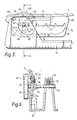
- Figure 3 is a fragmentary side view on an enlarged scale of the locking mechanism of the seat shown in Figure 1;
- Figure 4 is a cross-sectional view taken on the line 4 - 4 in Figure 3;
- Figure 5 is a fragmentary side view, similar to Figure 3, of a modified embodiment of the invention; and
- Figure 6 is a cross-sectional view taken on the line 6 - 6 in Figure 5.
- Referring to Figure 1, a child's safety seat consists of a
seat body 10 having aseat portion 12 and aback rest portion 14. Theseat body 10 is mounted on an L-shaped support member 16 having abase limb 18 and an upwardly extendingback limb 20. - The upper end of the
back limb 20 of thesupport member 16 is bent forwardly and carries atransverse pin 22 which engages in aslot 24 in theback portion 14 of theseat body 10, theslot 24 extending substantially parallel to the back rest thereof. A generallytriangular projection 26 is formed integrally with the front end of thebase limb 18 and carries atransverse pin 28 which engages in aslot 30 formed in aflange 32 secured to the bottom surface of theseat portion 12. - It should be appreciated that a similar pin to the
pin 22 projects from the opposite side of theback limb 20 into engagement with a similar slot to theslot 24 on the other side of theseat body 10, and that a similar pin to thepin 28 projects from another triangular projection on the other side of thebase limb 18 into engagement with a slot similar to theslot 30 in another flange similar to theflange 32 on the other side of the bottom of theseat portion 12. Theseat body 10 is thus supported on thesupport member 16 at four locations. - In Figure 1 the
pin 28 is shown at the front end of theslot 30 and thepin 22 at the bottom end of theslot 24. Theseat body 10 is in its most upright position. Referring to Figure 2, theseat body 10 can be moved relative to thesupport member 16 to bring thepins respective slots seat body 10 in its fully reclined position. Theseat body 10 takes up a succession of intermediate positions as thepins respective slots - In order to secure the seat body in a desired position, a row of six uniformly spaced open-
ended detent slots 34 are formed in the bottom edge of theflange 32. As can best be seen in Figures 3 and 4, a pair oflocking plates flange 32 and interconnected by a pair oflocking studs detent slots 34. Astub axle 44 is secured fast with thelocking plate 36 so as to project outwardly through a substantiallyvertical guide slot 46 in thetriangular projection 26 and carries acontrol knob 48 on its outer end. - Co-axially with the
stub axle 44, acontrol rod 50 extends from theother locking plate 38 under theseat body 10 to the other side of thesupport member 16, where it is secured to a similar locking mechanism (not shown) which engages with the above-mentioned flange correspnoding to theflange 32. The common axis of thecontrol rod 50 and thestub axle 44 is located half way betwen the twolocking studs - A vertically extending
cylindrical housing 52, secured to thebase limb 18 of thesupport member 16, contains aplunger 54 which is upwardly biased by acompression spring 56 so as to engage with thecontrol rod 50, thereby to urge thestub axle 44 to the top of theguide slot 46. - When the mechanism is in the position shown in Figures 1, 3 and 4, the engagement of the two
locking studs detent slots 34 in theflange 32 prevent movement of theseat body 10 relative to thesupport member 16. If theknob 48 is turned in the counter-clockwise direction, as viewed in Figures 1 and 3, thelocking plates locking pin 42 nearer to the rear of theflange 32, so that theother locking pin 40 moves out of engagement with the frontdetent slot 34 and thestub axle 44 moves downwardly in theguide slot 46. - Continued rotation of the
knob 48 brings thelocking pin 40 into engagement with the third of thedetent slots 34 from the front. Theseat 10 is now secured in its next stable position, thecompression spring 56 preventing the mechanism remaining in any position in which bothlocking pins adjacent slots 34. Continued rotation of theknob 48 causes theseat body 10 to take up successive positions of increasing inclination until thestud 42 is received in the rearmostdetent slot 34, as shown in Figure 2. Rotation of theknob 48 in the clockwise direction, as viewed in Figures 1, 2, and 3, moves theseat body 10 to a more upright position. - Figures 5 and 6 illustrate a modified embodiment of the invention in which parts identical with corresponding parts of the embodiments shown in Figures 3 and 4 are denoted by the same reference numerals and will not be described again in detail. The
flange 32 is replaced by a muchdeeper flange 60 containing anelongate opening 62 near its bottom edge. The open-ended detent slots 38 are formed along the upper edge of the opening 62. Theouter locking plate 36 of Figures 1 to 4 is replaced by an enlargedlocking plate 64 having twocam lobes 66 and 68 extending in opposite directions perpendicular to the line joining thelocking studs flange 60 has astep formation 70, 72, arranged to position thelower edge 74 of the opening 62 in alignment with thelocking plate 64. Thelower edge 74 of the opening 62 is in the shape of a complementary cam formation such as to remain in constant engagement with the periphery of thelocking plate 64 formed by thecam lobes 66 and 68. Thecam lobes 66 and 68 thus prevent downward movement of thestub axle 44 except in conjunction with rotational movement thereof, thereby ensuring that at least one of thelocking studs detent slots 38 at all times. Thepin 28 andslot 30 are not essential but their presence is preferable since they reduce friction by holding thecam lobes 66 and 68 out of engagement with thelower edge 74 except when an attempt is made to move bothlocking studs detent slots 38 simultaneously. - The
compression spring 56 of Figures 1 to 4 is replaced by atension spring 76 which extends between thecontrol rod 50 and asaddle formation 78 projecting upwardly from thebase limb 18. - The
compression spring 56 of Figures 1 to 4 may be used with the embodiment of Figures 5 and 6 and thetension spring 76 of Figures 5 and 6 may be used with the embodiment of Figures 1 to 4.
Claims (6)
Applications Claiming Priority (2)
| Application Number | Priority Date | Filing Date | Title |
|---|---|---|---|
| GB8800964 | 1988-01-16 | ||
| GB888800964A GB8800964D0 (en) | 1988-01-16 | 1988-01-16 | Child safety seat |
Publications (4)
| Publication Number | Publication Date |
|---|---|
| EP0325352A2 true EP0325352A2 (en) | 1989-07-26 |
| EP0325352A3 EP0325352A3 (en) | 1990-02-07 |
| EP0325352B1 EP0325352B1 (en) | 1993-04-07 |
| EP0325352B2 EP0325352B2 (en) | 1995-12-13 |
Family
ID=10630074
Family Applications (1)
| Application Number | Title | Priority Date | Filing Date |
|---|---|---|---|
| EP89300170A Expired - Lifetime EP0325352B2 (en) | 1988-01-16 | 1989-01-10 | Child's safety seat |
Country Status (6)
| Country | Link |
|---|---|
| EP (1) | EP0325352B2 (en) |
| JP (1) | JPH01214313A (en) |
| AU (1) | AU607301B2 (en) |
| DE (1) | DE68905829T2 (en) |
| GB (1) | GB8800964D0 (en) |
| NZ (1) | NZ227627A (en) |
Cited By (11)
| Publication number | Priority date | Publication date | Assignee | Title |
|---|---|---|---|---|
| GB2240035A (en) * | 1989-12-21 | 1991-07-24 | Combi Co | Auxiliary chair for vehicle |
| FR2666284A1 (en) * | 1990-09-04 | 1992-03-06 | Gerry Baby Prod | CAR SEAT FOR MULTIPURPOSE CHILD WITH LOUNGE. |
| FR2687960A1 (en) * | 1992-03-02 | 1993-09-03 | Baby Relax Snc | Safety car seat for a child |
| FR2706827A1 (en) * | 1993-06-21 | 1994-12-30 | Baby Relax | Safety car seat for a child |
| AU663384B2 (en) * | 1992-10-13 | 1995-10-05 | Century Products Company | Automobile infant restraint seat |
| WO1996011819A1 (en) * | 1994-10-14 | 1996-04-25 | Dunlop Cox Ltd. | Height adjustment device for vehicle seats |
| FR2768091A1 (en) * | 1997-09-10 | 1999-03-12 | Car Seat Specialty Inc | Child seat for motor vehicle |
| WO2005002907A1 (en) * | 2003-07-02 | 2005-01-13 | Concord Gmbh | Child seat |
| WO2005054003A1 (en) * | 2003-12-01 | 2005-06-16 | Graco Children's Products Inc. | Recline mechanism for a vehicle child seat |
| WO2007107806A1 (en) * | 2006-03-17 | 2007-09-27 | Play, S.A. | Base for a child's safety seat for motor vehicles |
| US11291307B2 (en) * | 2018-04-20 | 2022-04-05 | Ergotech Solutions, Inc. | Body support |
Families Citing this family (3)
| Publication number | Priority date | Publication date | Assignee | Title |
|---|---|---|---|---|
| EP0424303A3 (en) * | 1989-10-20 | 1991-10-23 | Play, S.A. | Tiltable child's seat |
| US5181761A (en) * | 1991-09-12 | 1993-01-26 | Lisco, Inc. | Child restraint system |
| CN103991393B (en) | 2013-02-16 | 2016-11-02 | 明门香港股份有限公司 | Chair angle guiding mechanism and the child safety chair with this mechanism |
Citations (4)
| Publication number | Priority date | Publication date | Assignee | Title |
|---|---|---|---|---|
| US3645548A (en) * | 1969-07-28 | 1972-02-29 | Arthur N Briner | Safety auto seat |
| DE2221489A1 (en) * | 1972-05-02 | 1973-11-15 | Morellet Guerineau Ets | CAR SEAT, IN PARTICULAR CHILD CAR SEAT |
| EP0116965A2 (en) * | 1983-02-19 | 1984-08-29 | C. Rob. Hammerstein GmbH | Tilt adjustment device for vehicle seats |
| EP0228158A2 (en) * | 1985-10-30 | 1987-07-08 | Ase (Uk) Limited | Child's safety seat |
-
1988
- 1988-01-16 GB GB888800964A patent/GB8800964D0/en active Pending
-
1989
- 1989-01-10 DE DE68905829T patent/DE68905829T2/en not_active Expired - Fee Related
- 1989-01-10 EP EP89300170A patent/EP0325352B2/en not_active Expired - Lifetime
- 1989-01-13 AU AU28465/89A patent/AU607301B2/en not_active Ceased
- 1989-01-16 NZ NZ22762789A patent/NZ227627A/en unknown
- 1989-01-17 JP JP843389A patent/JPH01214313A/en active Pending
Patent Citations (4)
| Publication number | Priority date | Publication date | Assignee | Title |
|---|---|---|---|---|
| US3645548A (en) * | 1969-07-28 | 1972-02-29 | Arthur N Briner | Safety auto seat |
| DE2221489A1 (en) * | 1972-05-02 | 1973-11-15 | Morellet Guerineau Ets | CAR SEAT, IN PARTICULAR CHILD CAR SEAT |
| EP0116965A2 (en) * | 1983-02-19 | 1984-08-29 | C. Rob. Hammerstein GmbH | Tilt adjustment device for vehicle seats |
| EP0228158A2 (en) * | 1985-10-30 | 1987-07-08 | Ase (Uk) Limited | Child's safety seat |
Cited By (14)
| Publication number | Priority date | Publication date | Assignee | Title |
|---|---|---|---|---|
| GB2240035A (en) * | 1989-12-21 | 1991-07-24 | Combi Co | Auxiliary chair for vehicle |
| US5052750A (en) * | 1989-12-21 | 1991-10-01 | Combi Corporation | Tiltable auxiliary chair having locking means and pivotal seat belt engagement plate for forward and rearward facing |
| GB2240035B (en) * | 1989-12-21 | 1993-03-10 | Combi Co | Auxiliary chair for vehicle |
| FR2666284A1 (en) * | 1990-09-04 | 1992-03-06 | Gerry Baby Prod | CAR SEAT FOR MULTIPURPOSE CHILD WITH LOUNGE. |
| FR2687960A1 (en) * | 1992-03-02 | 1993-09-03 | Baby Relax Snc | Safety car seat for a child |
| AU663384B2 (en) * | 1992-10-13 | 1995-10-05 | Century Products Company | Automobile infant restraint seat |
| FR2706827A1 (en) * | 1993-06-21 | 1994-12-30 | Baby Relax | Safety car seat for a child |
| WO1996011819A1 (en) * | 1994-10-14 | 1996-04-25 | Dunlop Cox Ltd. | Height adjustment device for vehicle seats |
| FR2768091A1 (en) * | 1997-09-10 | 1999-03-12 | Car Seat Specialty Inc | Child seat for motor vehicle |
| WO2005002907A1 (en) * | 2003-07-02 | 2005-01-13 | Concord Gmbh | Child seat |
| US7328948B2 (en) | 2003-07-02 | 2008-02-12 | Concord Gmbh | Child seat |
| WO2005054003A1 (en) * | 2003-12-01 | 2005-06-16 | Graco Children's Products Inc. | Recline mechanism for a vehicle child seat |
| WO2007107806A1 (en) * | 2006-03-17 | 2007-09-27 | Play, S.A. | Base for a child's safety seat for motor vehicles |
| US11291307B2 (en) * | 2018-04-20 | 2022-04-05 | Ergotech Solutions, Inc. | Body support |
Also Published As
| Publication number | Publication date |
|---|---|
| EP0325352A3 (en) | 1990-02-07 |
| EP0325352B1 (en) | 1993-04-07 |
| JPH01214313A (en) | 1989-08-28 |
| EP0325352B2 (en) | 1995-12-13 |
| DE68905829D1 (en) | 1993-05-13 |
| GB8800964D0 (en) | 1988-02-17 |
| AU607301B2 (en) | 1991-02-28 |
| NZ227627A (en) | 1990-06-26 |
| AU2846589A (en) | 1989-07-20 |
| DE68905829T2 (en) | 1996-10-02 |
Similar Documents
| Publication | Publication Date | Title |
|---|---|---|
| EP0325352A2 (en) | Child's safety seat | |
| US5415459A (en) | Adjustable width arm rest | |
| EP0188732B1 (en) | Headrest | |
| US6000760A (en) | Device for tilting headrest for automobile and device for moving headrest forward and backward in which the tilting device is used | |
| US5335964A (en) | Automobile infant restraint seat | |
| US3866876A (en) | Seat slide mechanism | |
| CA2516965C (en) | Chair adjustment mechanism | |
| EP0608597B1 (en) | Child's safety device | |
| US6347833B1 (en) | High chair having a seat-tilting mechanism | |
| US5016846A (en) | Spring and lock support for overbed table | |
| US6722734B2 (en) | Locking assembly for a rocking chair | |
| WO1981002549A1 (en) | Latch assembly | |
| EP0331299A2 (en) | Child's safety seat | |
| EP0486184B1 (en) | Car bed for infants | |
| US6264276B1 (en) | Adjustable connecting device for interconnecting seat and backrest members of a chair | |
| EP0076171A2 (en) | Mechanism for adjusting the angle of elevation of an object | |
| EP0091936B1 (en) | Tilting mechanism for a chair | |
| US6209963B1 (en) | Variable configuration mounting arrangement for a chair back support member | |
| JP4255183B2 (en) | child seat | |
| JP4650658B2 (en) | Reclining device for stroller | |
| JPH0523097Y2 (en) | ||
| JPS637080Y2 (en) | ||
| EP0532476A1 (en) | Chair back stand adjustable for height | |
| JPH0421318Y2 (en) | ||
| JPH0630548Y2 (en) | Walk-in lock mechanism in seat track slide device |
Legal Events
| Date | Code | Title | Description |
|---|---|---|---|
| PUAI | Public reference made under article 153(3) epc to a published international application that has entered the european phase |
Free format text: ORIGINAL CODE: 0009012 |
|
| AK | Designated contracting states |
Kind code of ref document: A2 Designated state(s): DE GB IT |
|
| PUAL | Search report despatched |
Free format text: ORIGINAL CODE: 0009013 |
|
| AK | Designated contracting states |
Kind code of ref document: A3 Designated state(s): DE GB IT |
|
| 17P | Request for examination filed |
Effective date: 19900115 |
|
| RAP1 | Party data changed (applicant data changed or rights of an application transferred) |
Owner name: BRITAX ROEMER KINDERSICHERHEIT GMBH |
|
| 17Q | First examination report despatched |
Effective date: 19920220 |
|
| RAP1 | Party data changed (applicant data changed or rights of an application transferred) |
Owner name: BRITAX ROEMER KINDERSICHERHEIT GMBH |
|
| GRAA | (expected) grant |
Free format text: ORIGINAL CODE: 0009210 |
|
| AK | Designated contracting states |
Kind code of ref document: B1 Designated state(s): DE GB IT |
|
| ITF | It: translation for a ep patent filed |
Owner name: ING. A. GIAMBROCONO & C. S.R.L. |
|
| REF | Corresponds to: |
Ref document number: 68905829 Country of ref document: DE Date of ref document: 19930513 |
|
| PLBI | Opposition filed |
Free format text: ORIGINAL CODE: 0009260 |
|
| 26 | Opposition filed |
Opponent name: MAXI MILIAAN B.V. Effective date: 19940107 |
|
| PUAH | Patent maintained in amended form |
Free format text: ORIGINAL CODE: 0009272 |
|
| STAA | Information on the status of an ep patent application or granted ep patent |
Free format text: STATUS: PATENT MAINTAINED AS AMENDED |
|
| 27A | Patent maintained in amended form |
Effective date: 19951213 |
|
| AK | Designated contracting states |
Kind code of ref document: B2 Designated state(s): DE GB IT |
|
| PGFP | Annual fee paid to national office [announced via postgrant information from national office to epo] |
Ref country code: DE Payment date: 19960115 Year of fee payment: 8 |
|
| PG25 | Lapsed in a contracting state [announced via postgrant information from national office to epo] |
Ref country code: DE Effective date: 19971001 |
|
| PGFP | Annual fee paid to national office [announced via postgrant information from national office to epo] |
Ref country code: GB Payment date: 20000105 Year of fee payment: 12 |
|
| PG25 | Lapsed in a contracting state [announced via postgrant information from national office to epo] |
Ref country code: GB Free format text: LAPSE BECAUSE OF NON-PAYMENT OF DUE FEES Effective date: 20010110 |
|
| GBPC | Gb: european patent ceased through non-payment of renewal fee |
Effective date: 20010110 |
|
| PG25 | Lapsed in a contracting state [announced via postgrant information from national office to epo] |
Ref country code: IT Free format text: LAPSE BECAUSE OF NON-PAYMENT OF DUE FEES;WARNING: LAPSES OF ITALIAN PATENTS WITH EFFECTIVE DATE BEFORE 2007 MAY HAVE OCCURRED AT ANY TIME BEFORE 2007. THE CORRECT EFFECTIVE DATE MAY BE DIFFERENT FROM THE ONE RECORDED. Effective date: 20050110 |