EP0325200A2 - Rotary valve - Google Patents
Rotary valve Download PDFInfo
- Publication number
- EP0325200A2 EP0325200A2 EP89100719A EP89100719A EP0325200A2 EP 0325200 A2 EP0325200 A2 EP 0325200A2 EP 89100719 A EP89100719 A EP 89100719A EP 89100719 A EP89100719 A EP 89100719A EP 0325200 A2 EP0325200 A2 EP 0325200A2
- Authority
- EP
- European Patent Office
- Prior art keywords
- valve body
- valve
- casings
- cylindrical hole
- rotator
- Prior art date
- Legal status (The legal status is an assumption and is not a legal conclusion. Google has not performed a legal analysis and makes no representation as to the accuracy of the status listed.)
- Granted
Links
Images


Classifications
-
- F—MECHANICAL ENGINEERING; LIGHTING; HEATING; WEAPONS; BLASTING
- F16—ENGINEERING ELEMENTS AND UNITS; GENERAL MEASURES FOR PRODUCING AND MAINTAINING EFFECTIVE FUNCTIONING OF MACHINES OR INSTALLATIONS; THERMAL INSULATION IN GENERAL
- F16K—VALVES; TAPS; COCKS; ACTUATING-FLOATS; DEVICES FOR VENTING OR AERATING
- F16K11/00—Multiple-way valves, e.g. mixing valves; Pipe fittings incorporating such valves
- F16K11/02—Multiple-way valves, e.g. mixing valves; Pipe fittings incorporating such valves with all movable sealing faces moving as one unit
- F16K11/06—Multiple-way valves, e.g. mixing valves; Pipe fittings incorporating such valves with all movable sealing faces moving as one unit comprising only sliding valves, i.e. sliding closure elements
- F16K11/072—Multiple-way valves, e.g. mixing valves; Pipe fittings incorporating such valves with all movable sealing faces moving as one unit comprising only sliding valves, i.e. sliding closure elements with pivoted closure members
- F16K11/074—Multiple-way valves, e.g. mixing valves; Pipe fittings incorporating such valves with all movable sealing faces moving as one unit comprising only sliding valves, i.e. sliding closure elements with pivoted closure members with flat sealing faces
-
- F—MECHANICAL ENGINEERING; LIGHTING; HEATING; WEAPONS; BLASTING
- F16—ENGINEERING ELEMENTS AND UNITS; GENERAL MEASURES FOR PRODUCING AND MAINTAINING EFFECTIVE FUNCTIONING OF MACHINES OR INSTALLATIONS; THERMAL INSULATION IN GENERAL
- F16K—VALVES; TAPS; COCKS; ACTUATING-FLOATS; DEVICES FOR VENTING OR AERATING
- F16K3/00—Gate valves or sliding valves, i.e. cut-off apparatus with closing members having a sliding movement along the seat for opening and closing
- F16K3/02—Gate valves or sliding valves, i.e. cut-off apparatus with closing members having a sliding movement along the seat for opening and closing with flat sealing faces; Packings therefor
- F16K3/04—Gate valves or sliding valves, i.e. cut-off apparatus with closing members having a sliding movement along the seat for opening and closing with flat sealing faces; Packings therefor with pivoted closure members
- F16K3/06—Gate valves or sliding valves, i.e. cut-off apparatus with closing members having a sliding movement along the seat for opening and closing with flat sealing faces; Packings therefor with pivoted closure members in the form of closure plates arranged between supply and discharge passages
- F16K3/08—Gate valves or sliding valves, i.e. cut-off apparatus with closing members having a sliding movement along the seat for opening and closing with flat sealing faces; Packings therefor with pivoted closure members in the form of closure plates arranged between supply and discharge passages with circular plates rotatable around their centres
- F16K3/085—Gate valves or sliding valves, i.e. cut-off apparatus with closing members having a sliding movement along the seat for opening and closing with flat sealing faces; Packings therefor with pivoted closure members in the form of closure plates arranged between supply and discharge passages with circular plates rotatable around their centres the axis of supply passage and the axis of discharge passage being coaxial and parallel to the axis of rotation of the plates
-
- Y—GENERAL TAGGING OF NEW TECHNOLOGICAL DEVELOPMENTS; GENERAL TAGGING OF CROSS-SECTIONAL TECHNOLOGIES SPANNING OVER SEVERAL SECTIONS OF THE IPC; TECHNICAL SUBJECTS COVERED BY FORMER USPC CROSS-REFERENCE ART COLLECTIONS [XRACs] AND DIGESTS
- Y10—TECHNICAL SUBJECTS COVERED BY FORMER USPC
- Y10T—TECHNICAL SUBJECTS COVERED BY FORMER US CLASSIFICATION
- Y10T137/00—Fluid handling
- Y10T137/8593—Systems
- Y10T137/86493—Multi-way valve unit
- Y10T137/86574—Supply and exhaust
- Y10T137/86622—Motor-operated
-
- Y—GENERAL TAGGING OF NEW TECHNOLOGICAL DEVELOPMENTS; GENERAL TAGGING OF CROSS-SECTIONAL TECHNOLOGIES SPANNING OVER SEVERAL SECTIONS OF THE IPC; TECHNICAL SUBJECTS COVERED BY FORMER USPC CROSS-REFERENCE ART COLLECTIONS [XRACs] AND DIGESTS
- Y10—TECHNICAL SUBJECTS COVERED BY FORMER USPC
- Y10T—TECHNICAL SUBJECTS COVERED BY FORMER US CLASSIFICATION
- Y10T137/00—Fluid handling
- Y10T137/8593—Systems
- Y10T137/86493—Multi-way valve unit
- Y10T137/86574—Supply and exhaust
- Y10T137/86638—Rotary valve
Definitions
- the present invention relates to a rotary valve which may readily be produced, may ensure a high responsibility with a small drive force with a high precision in control, may be made small in size and light in weight, and may readily be reused in its valve portion. More particularly, it relates to a structure and a producing method for a rotary valve used as a direct drive type rotary servo valve and for a hydraulic pressure control unit of a rolling machine.
- grooves extending in an axial direction are formed in an outer surface of a cylindrical valve body and in an inner surface of a casing for receiving the valve body; a valve portion for forming control orifices with edges of side surfaces of these inner and outer grooves is used; and a disc-shaped rotator is integrally coupled to the end portion of the valve body to drive the valve body and to change an opening area of the control orifices.
- sleeves are provided in parallel with a rotary center axis of the valve body, and flow paths are spaced from each other by the sleeves and are formed on both sides of the valve body.
- cylindrical holes having an inner diameter substantially equal to an outer diameter of the sleeves are formed coaxially with the sleeves in the casing.
- a disc-shaped rotator is integrally coupled to a part of the valve body to drive the valve body. The relative motion between the sleeves and the cylindrical holes causes the opening area of the control orifices, formed by the outer edges of the sleeve, the inner edges of the cylindrical holes and the inner and outer edges of the flow paths, to change.
- valve body if the flow paths are formed in the valve body, there is a problem that the valve body would be enlarged in size in order to increase the cross-sectional area of the flow paths to ensure satisfactory flow rate control characteristics. Also, since the sleeves are provided in the valve body, it is necessary to provide partition walls and outer walls having mechanical strength enough to suppress any deformation of the valve body in high pressure parts. In addition, since the structure of the valve body is intricate, a stress concentration would be likely to be generated particularly in connection parts between the partition walls and the outer walls. In order to avoid this defect, it is necessary to provide additional reinforcements. As a result, the valve body would be enlarged in size to increase inertia moments. It would be impossible to ensure a high responsibility.
- An object of the present invention is to provide a rotary valve which may readily be manufactured, may ensure a high responsibility with a small drive force with a high precision in control, may be made small in size and light in weight, and may readily be reused in its valve portion and to provide a hydraulic control apparatus for a rolling machine which uses the rotary valve.
- a rotary valve comprises casings and a valve body rotatably provided within the casings, in which a relative motion between the valve body and the casings causes the flow of fluid to be controlled.
- the present invention is characterized in that the valve body has cylindrical holes, and the casings have sleeves or plugs having an outer diameter substantially equal to an inner diameter of the cylindrical holes.
- the servo valve comprises a valve body having cylindrical holes, a drive means having a rotator integrally coupled to a part of the valve body, and casings having sleeves or plugs, having an outer diameter substantially equal to an inner diameter of the cylindrical holes of the valve body, in coaxial relation with the cylindrical holes of the valve body, for rotatably supporting the valve body.
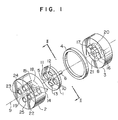
- This embodiment relates to a valve portion of a four-way valve.
- a valve body 1 and a spacer 4 are clamped by casings 2 and 3.
- a thickness of the spacer 4 is slightly larger than an axial thickness of the valve body 1 by a predetermined level.
- Shafts 5 and 6 extend from end faces of the valve body to form radial bearings in corporation with axial holes 7 and 8 formed in the casings 2 and 3, respectively. Therefore, the valve body 1 is rotatably supported about a rotary center axis 9 relative to the casings 2 and 3 and the spacer 4.
- valve body 1 there are formed cylindrical holes 10 and 11 in parallel with the rotary center axis 9 and through hole portions 12 and 13.
- the casings 2 and 3 there are formed sleeves 14 and 15 and plugs 16 and 17 having an outer diameter substantially equal to an inner diameter of the cylindrical holes 10 and 11 of the valve body 1, and there are formed flow paths 18 and 19, and 20 and 21 which are separated from each other by the sleeves 14 and 15 and the plugs 16 and 17, respectively.
- control ports 22 and 23 are connected to inner portions of the sleeves 14 and 15, a supply port 24 is connected to the flow path 18, and discharge port 25 is connected to the flow path 19.
- the flow paths 18 and 20 are in communication with each other through hole portion 12, and the flow paths 19 and 21 are in communication with each other through hole portion 13.
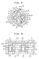
- Figs. 2 and 3 show a neutral condition, that is, a condition in which the valve is closed to interrupt the flow of the fluid. Under this condition, since the inner edges of the cylindrical holes 10 and 11 are aligned with the outer edges of the sleeves 14 and 15 and the plugs 16 and 17, respectively, the control ports 22 and 23 are partitioned by the supply port 24 and the discharge port 25, to interrupt the flow of fluid.
- opening areas 27, 28 and 29, 30 defined by the inner edges of the cylindrical holes 10, 11 and the outer edges of the plugs 16, 17 and the inner and outer edges of the flow paths 18, 19 and 20, 21 are formed on both sides of the valve body 1. These opening areas serve as control orifices. Therefore, the control port 22 is communicated to the discharge port 25 through the control orifices 27 and 28, whereas the control port 23 is communicated to the supply port 24 through the control orifices 29 and 30, so that the fluid will flow from the supply port 24 to the control port 23 and from the control port 22 to the discharge port 25 as indicated by the arrows in Fig. 5.
- valve body 1 is rotated in the direction opposite to the direction indicated by the arrow 26, the control port 22 is in communication with the supply port 24 and the control port 23 is in communication with the discharge port 25, so that the fluid will flow reversely from the supply port 24 to the control port 22 and from the control port 23 to the discharge port 25.
- the opening areas of the control orifices are in proportion to an angular shift of the valve body 1. Since the flow rate depends upon the opening areas, the valve serves as a forward and reverse rotational type stepless, continuous variable four-way valve.
- the opening areas of the control orifices are increased to increase the flow rate.
- the flow velocity of the fluid flowing through the flow paths is increased, so that the velocity will gradually approach the flow velocity through the control orifices.
- a pressure loss through the flow paths is increased, so that the pressure difference between the portions downstream and upstream of the control orifices is decreased.
- the flow rate control characteristics of the valve is not in the linear relation. In order to avoid this, it is, therefore, necessary to increase the cross-sectional area of the flow paths in comparison with the opening area of the control orifices.
- the sleeves, the plugs and flow paths are formed on the casing side so that the magnitude of cross-sectional area of the flow paths would not directly affect the size of the valve body.
- the structure of the valve body is simple and any stress concentration or deformation would not be likely to be generated, it is unnecessary to impart an excess dimension to the valve body for the reason of the mechanical strength.
- the valve body may be made compact in size and light in weight. Accordingly, since the interia moment of the valve body may be reduced, it is possible to ensure a high responsibility even with a small drive force. Furthermore, since the high pressure parts extending from the supply port and terminating at the control port may be reduced to a minimum possible level, the valve portion as a whole may be made small in size and light in weight.
- the valve portion upon manufacturing the valve portion, it is sufficient to simultaneously machine the cylindrical holes 10, 11, and the holes of the casings 2 and 3 on which the sleeves 14, 15 and the plugs 16 and 17 are to be mounted, respectively, and then to mount the sleeves and the plugs on the valve body 1.
- the adjustment of the lap amount may be performed during the machining operation by adjusting the inner diameter of the cylindrical holes and the outer diameter of the plugs to a predetermined dimensional difference.
- the adjustment of the clearance may be performed by adjusting a thickness difference between the valve body 1 and the spacer 4. Accordingly, the manufacture method of the valve portion may be facilitated and the number of the manufacture steps may be reduced. In addition, it is possible to ensure the high precision in control.
- the orifice edges i.e., the inner edges of the end portions of the cylindrical holes 10, 11 and the outer edges of the end portions of the sleeves 14, 15 and the plugs 16, 17 are worn due to a long service life, or in the case where the orifice edges are partially damaged due to the entrainment of foreign matters
- the worn or damaged part is removed by again grinding the end faces of the valve body 1 and the casing 2, 3, and then the thickness of the spacer 4 is again adjusted so that the thickness of the spacer is larger than the axial thickness of the valve body 1 by the predetermined difference.
- the valve portion may restore the performance substantially equal to that of a new valve. It is therefore possible to readily reuse the valve portion.
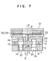
- FIG. 6 This arrangement is composed of the four-way valve in accordance with the embodiment shown in Figs. 1 through 5 and a drive means having a disc-shaped rotator.
- a drive means having a disc-shaped rotator.
- the disc-shaped rotator 30 is connected integrally with the shaft 6 of the valve body 1.
- the rotator 30 is clamped between a magnet 31 having a circular flat surface and yoke 32 to be rotatable at a predetermined space.
- the magnet 31 and the yoke 32 are fixed to the casing 3.
- a plurality of coils 33 are arranged circumferentially on the rotator 30 so that their widing directions are alternatively changed by every ⁇ degrees. Also, the polarity of each poles of the magnet 31 is changed by every ⁇ degrees in the circumferential direction. Then, in the neutral condition of the valve portion, the borders of adjacent cores 33 and the border of the adjacent poles of the magnet 31 are offset from each other by an angle of ⁇ /2.
- the rotator 30 and the valve body 1 are rotated in the direction opposite to the direction indicated by the arrow 34. Accordingly, it is possible to adjust the angular shift of the valve body in accordance with the direction of the magnitude of the current flowing through the coils 33 on the rotator 30, and to control the flow rate and the direction of fluid in proportion to this adjustment.
- the rotator is in the form of a disc, it is possible to particularly reduce a thickness of the drive means. Also, since the intertia moment of the valve body is small as described above, the output of the drive means may be small to thereby make the rotator small in size. Therefore, it is possible to ensure a high responsibility with a small drive force and the valve as a whole may be made small in size and light in weight. In addition, the comsumption energy and the heat generation of the drive means may be reduced.
- valve portion may be composed only of the valve body 1 and the casing 2.
- the plugs 16 and 17 formed in the caseing 3 and the flow paths formed therein may be dispensed with.
- the cylindrical holes 10 and 11 may be through-holes in the axial direction. This makes it further easier to manufacture the valve.
- Fig. 10 shows a modification of the embodiment shown in Figs. 6 through 8.
- Sleeves 16a and 17a are used instead of the plugs 16 and 17 used in the embodiment shown in Figs. 6 through 8.
- the valve body 1 is modified in configuration so that the part of the valve body 1 confronting with the flow paths 19 and 21 in communication with the discharge port 25 is removed, and the valve body 1 may cover the flow paths 18 and 20 in communication with the supply port 24, the sleeves 14, 15 and the sleeves 16a, 17a and the cylindrical holes 10 and 11.
- the yoke 32 is dispensed with, and the casing 3 may serve as the function of the yoke.
- valve body 1 is made further smaller, so that the intertia moment is further reduced. Also, the sliding area between the casings 2 and 3 and the valve body 1 is further reduced, so that a higher responsibility may be ensured even with further smaller drive force. Also, since the through hole portion 13 on the discharge port side may be dispensed with, it is further easier to manufacture the valve body 1. Furthermore, since the yoke is dispensed with, the assembling work or maintenance work are more readily performed as well as the manufacture work.
- the yoke of the magnetic circuit is different from the casing in use or object, it is general to use different materials.
- the present inventors have experimentally found that there is no practical problem at all even if the casing serves as the yoke. Thus, such an arrangement is possible.
- the reason for this is that since the casing is designed to have a mechanical strength enough to be durable against the high pressure, the magnetic flow paths through which the magnetic flux may readily pass are inherently provided and the magnetic field is static.
- Fig. 11 shows another embodiment for the drive portion.
- a rotator 35 coupled in unison with the valve body has a conical shape. Also, a magnet 36 and a surface, on the rotator 35 side, of a yoke 37 are conically formed. The rotator 35 is clamped between the magnet 36 and the yoke 37 to be rotatable at a predetermined space.
- the rotator 35 has a plurality of coils 38 that are switched over alternatively in their winding direction by an angle ⁇ in the circumferential direction. Also, the polarities of the magnet 36 are alternatively switched over by every angle ⁇ in the circumferential direction. Under the neutral condition, the borders of the respective coil 38 and the borders of the respective poles of the magnet 36 are offset from each other by an angle ⁇ /2.
- the drive force may be increased by increasing the axial length of the rotator 35 even if the radial dimension of the rotator 35 is kept constant, it is possible to provide a rotator having a large drive force and a small inertia moment by selecting the combination of the radial and axial dimensions at an optimum condition. It is therefore possible to reduce the necessary drive force and to ensure a higher responsibility with a smaller energy.
- the drive means is superior also in mechanical strength, may withstand a higher drive force transmission and is superior also in vibration-resistance property. It is therefore possible to ensure heigher reliability.
- Fig. 12 shows still another embodiment for the drive means.
- a rotator 39 connected in unison with the valve body is in the form of a cylinder.
- a magnet 40 and a surface, on the rotator 39 side, of a yoke 41 are in the form of cylinders.
- the rotator 39 is clamped between the magnet 40 and the yoke 41 to be rotatable at a predetermined space.
- the rotator 39 has a plurality of coils 42 whose winding directions are alternatively changed by every angle ⁇ in the circumferential direction.
- the polarities of the magnet 40 are alternatively changed by every angle ⁇ in the circumferential direction. Under the neutral condition, the borders of the respective poles of the magnet 40 and the borders of the respective poles of the coils 42 are offset from each other by every angle ⁇ /2.
- the drive force is increased in proportion to the axial length thereof, it is possible to provide a rotator which has a large drive force and a small inertia moment by selecting a combination of the radial and axial dimensions at an optimum level. It is therefore possible to further reduce the necessary drive force and to obtain a higher responsibility even with a further smaller energy.
- the rotator 39 is cylindrical, it is superior in mechanical strength and also in vibration resistant property while being durable against further large drive force. It is therefore possible to ensure higher reliability.
- FIG. 13 Another embodiment of the present invention will now be described with reference to Figs. 13 through 17.
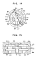
- This embodiment relates to a three-way valve.
- a valve body 43 is clamped by a casing 44 and a casing 45 together with a spacer 46.
- a thickness of the spacer 46 is larger than an axial thickness of the valve body 43 by a predetermined thickness difference.
- shafts 47 and 48 are extending from end faces of the valve body 43 to form a radial bearing between axial holes 49 and 50 formed in the casing 44 and 45. Accordingly, the valve body 43 is provided to rotatably about a rotational center axis 51 relative to the casings 44 and 45 and the spacer 46.
- a cylindrical hole 52 in parallel with the rotational center axis 51 and through hole portions 53 and 54.
- the casing 44 and 45 have a sleeve 55 and a plug 56 which have an outer diameter substantially equal to an inner diameter of the cylindrical hole 52 formed in the valve body 43, and flow paths 57, 58 and 59, 60 formed so as to be separated from each other by the sleeve 55 and the plug 56.
- a control port 61 is in communication with an inner diameter portion of the sleeve 55
- a supply port 62 is in communication with a flow path 57
- a discharge port 63 is in communication with a flow path 58.
- the flow paths 57 and 59 are in communication with each other through the through hole portion 53 and the flow paths 58 and 60 are in communication with each other through the through hole portion 54.
- Figs. 14 and 15 show a neutral condition, i.e., the condition in which the valve is closed to block the flow of the fluid. Under such a condition, since the inner edge is in alignment with the outer edges of the sleeve 55 and the plug 56, the control port is blocked from the supply port 62 and the discharge port 63, thus blocking the flow of the fluid.
- valve body 43 is rotated in the direction indicated by the arrow 64 so that the condition shown in Figs. 16 and 17 is obtained. Opening portions 65 and 66 surrounded by the inner edges of the cylindrical hole 52, the outer edges of the sleeve 55 and the plug 56, and the inner and outer edges of the flow paths 57 and 59 will appear to serve as control orifices. Therefore, the control port 61 is in communication with the supply port 62 through the control orifices 65 and 66, so that the fluid will flow from the supply port 62 to the control port 61 as indicated by the arrows in Fig. 17.
- the valve serves as a forward and reverse rotational type, stepless, continuous variable three-way valve.
- the structure in accordance with this embodiment is such that the magnitude of the flow path cross sectional area does not directly affect the size of the valve body since the sleeve, the plug and the flow paths are formed on the casing side in the same manner as in the embodiment of the four-way valve. Also, since the structure of the valve body is simple and the stress concentration and deformation would be unlikely to be produced, it is unnecessary to impart a dimensional excess to the valve body for the mechanical strength.
- the valve body may be made small in size and light in weight. Also, it is possible to reduce the consumption energy and the heat generation in the drive means. Furthermore, since the high pressure part extending from the supply port and terminating at the control port is suppressed at a necessary minimum level, the valve portion per se may be made small in size and light in weight.
- the adjustment of the lap amount may be performed by adjusting the difference in dimension between the inner diameter of the cylindrical hole and the outer diameter of the sleeve and the plug at a predetermined level during the maching work. Accordingly, it is easy to manufacture the valve portion and to reduce the number of manufacture steps. In addition, a high accuracy may be ensured even in control.
- the damaged or worn portion is removed by again grinding the end faces of the valve body 43 and the casings 44 and 45, and by adjusting the orifice edges so that the thickness of the spacer 46 is again larger than the axial thickness of the valve body 43 by the predetermined thickness difference.
- the valve portion may restore the function substantially equal to that of a new one, so that the valve portion may readily be reused.
- FIG. 18 shows a valve body composed of the valve portion of the three-way valve shown in Figs. 13 through 17 and the drive means having the disc-shaped rotator.
- the operation and the structure of the valve body is the same as that of the foregoing embodiment.
- a shaft 48 of the valve body 43 is coupled fixedly to a disc-shaped.
- the rotator 67 is clamped between the magnet 68 and the yoke 69 having circular flat surfaces so as to be rotatable at a predetermined space, and the magnet 68 and the yoke 69 are fixedly secured to the casing 59.
- a plurality coils 70 are provided on the rotator 67 so that their winding directions are alternatively changed by every angle ⁇ in the circum ferential direction.
- the polarities of the respective poles of the magnet 68 are alternatively changed by every angle ⁇ in the circumferential direction.
- the rotator 67 is coupled to the valve body 43 so that the borders of the respective coils 70 and the borders of the respective poles of the magnet 68 are offset from each other by an angle of ⁇ /2.
- the rotator is in the form of a disc, it is possible to reduce a thickness of the drive means in particular, and also, since the inertia moment of the valve body is small as described above, it is possible to reduce the rotator due to the fact that the output of the drive means may be reduced. Accordingly, it is possible to make the valve body as a whole small in size and light in weight, it is possible to ensure a high responsibility with a small drive force. It is also possible to reduce the consumption energy and the heat generation of the drive means.
- the plug 56 provided in the casing 45 by the sleeve.
- the magnet 68 it is possible to modify it so that the respective poles of the magnet as a whole may be polygonal or the respective poles may be separate and independent circular to polygonal ones. Thus, it is possible to more facilitate the manufacture.
- valve arrangement may be composed solely of the valve body 43 and the casing 44 in the same manner as in the embodiment shown in Fig. 9. Thus, it is much easire to manufacture the valve portion.
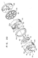
- Fig. 20 shows a modification of the embodiment shown in Figs. 18 and 19.
- a sleeve 56a is provided instead of the plug 56 shown in the embodiment of Figs. 18 and 19.
- the valve body 43 is modified in configuration so that the part, confronting with the flow paths 58 and 60 in communication with the discharge port 63, of the valve body 43 is removed, and the valve body 43 may cover the flow paths 57 and 59 in communication with the supply port 62, the sleeve 55 and the sleeve 56a in communication with the control port 61.
- the yoke 69 is dispensed with, and the casing 45 may serve the function of the yoke 69.
- valve body 43 is made small in size and light in weight, the inertia moment is further reduced. Since the sliding surface area between the valve body 43 and the casings 44 and 45 is small, it is possible to ensure a higher responsibility with a further smaller drive force. Also, since it is possible to dispense with the through hole portion 54 on the discharge port side, it is much easier to manufacture the valve body 43. Furthermore, since the yoke is also dispensed with, the assembling work and maintenance work may readily be performed as well as the manufacture work.
- Fig. 21 shows an embodiment of a direct drive type rotary servo valve system using a rotary valve in accordance with the invention.
- an angular shift detector 71 is provided for detecting the angular shift of the valve body 43 and the rotator 67.
- a shaft 72 of the angular shift detector 71 is connected to the valve body 43 and the rotator 67 and is rotated together therewith.
- an angular shift signal 73 detected by the angular shift detector 71 is fed back into a controller 74 where this value is compaired with a shift signal 77 of an object 76 to be controlled and a reference value 75.
- the difference therebetween is amplified to form a control command signal 78 which is given to the coils 70 on the rotator 67, thus forming a positional servo system.
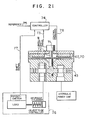
- Fig. 22 shows another embodiment of a direct drive type rotary servo valve system using the rotary valve according to the invention.
- a tortion spring 79 is provided on the shafts of the valve body 43 and the rotator 67.
- the tortion spring 79 are connected at one end to the valve body 43 and the rotator 67, and at the other end to the magnet 68.
- valve body 43 and the rotator 67 are rotated, a t réelle moment against the rotation will be generated in the tortion spring 79.
- the valve body 43 and the rotator 67 are stopped at the position where the moment is balanced with the moment of the drive force generated on the rotator 67, thus determining the flow rate of fluid.
- the controller 74 the reference value 75 and the shift signal 77 of the object 76 to be controlled are compaired with each other to amplify the deviation therebetween and to impart the deviation to the coils 70 on the rotator 67 to form a positional serve system.
- the same effects inherent to the foregoing embodiments may be obtained and the inertia of the rotational parts is small. It is therefore possible to readily increase the inherent value of the servo valve even with a soft spring. It is possible to obtain a high and stable frequency characteristic with a small drive force. Accordingly, since the consumption energy is small, the heat generation from the drive means is small. Since the power amplifying ability of the controller may be small, it is possible to make the controller small in size. Also, since a tortion spring is used, in the case of a rubber spring, for example, a Poisson ratio affect is small unlike a tension or compression spring, a hysterisis is small, so that it is possible to ensure a higher control precision.
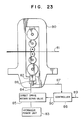
- Fig. 23 shows an embodiment of a hydraulic control unit for a rolling machine using a direct drive type rotary servo valve according to the invention.
- a rolling machine 80 comprises a hydraulic cylinder 82 used as a pressure means for imparting a rolling load to a material 81 to be rolled, and a direct drive type rotary servo valve 85 disposed in a midway of a pipe 84 for supplying a high pressure fluid from a hydraulic power unit 83 to the hydraulic cylinder 82. Also, a shift detector 86 is provided in the hydraulic cylinder 86, a shift signal 87 detected by the shift detector 86 is fed back to a controller 88. Then, in the controller 88, the shift signal 87 and a reference value 89 are compared with each other, to amplify the deviation therebetween and to impart a command signal 90 to the direct drive type rotary servo valve 85.
- the direct drive type rotary servo valve 85 may readily be manufactured with a high precision in control, it is possible to exactly control a thickness of a discharged plate material of the rolled material 81. Therefore, it is possible to provide a good rolled product in a stable manner at all the times inspite of changes of various parameters. Also, since the direct drive type rotary servo valve 85 may ensure a high responsibility with a small drive force, the power amplifying ability of the controller 88 may be small, the controller 88 may be made small in size and the consumption energy or the heat generation may be reduced.
- the parts which are disposed at high pressure are reduced to a minimum possible level, the structure of the valve body is simple and the thickness of the valve body may be reduced, the valve portion may be made small in size and light in weight.
- the manufacturing of the valve portion it is possible to perform the simultaneous machining, and it is easy to adjust the lap amount and the clearance. It is possible to ensure the easy manufacture and the high precision manufacture. Therefore, it is easy to reduce the number of the manufacture steps and to reduce the cost of the manufacture.
- valve body is made small with a small inertia moment, it is possible to ensure a high responsibility with a small drive force. Therefore, the small drive means may be used. Thus, the consumption energy and the heat generation in the drive means may be reduced.
- valve portion may be reused. This is achieved with ease.
- the rotary valve according to the invention is applicable to the direct drive type rotary servo valve, it is possible to make the valve small in size and light in weight with a high control precision. It is further possible to enhance the inherent value of the servo valve, and to readily ensure the high responsibility. Therefore, it is possible to make the controller as well as the servo valve smaller in size, and the consumption energy and heat generation of the system may be reduced. The cost or running cost of the system as a whole may be reduced to offer an economical advantage.
- the direct drive type rotary servo valve according to the invention is applied to a hydraulic controller for a rolling machine, it is possible to provide a control system having a high precision and a high responsibility. It is possible to always keep the system under a good rolling condition. It is possible to obtain stable and good rolled projects. Accordingly, it is possible to enhance a quality and a yield of the rolled products.
Abstract
Description
- The present invention relates to a rotary valve which may readily be produced, may ensure a high responsibility with a small drive force with a high precision in control, may be made small in size and light in weight, and may readily be reused in its valve portion. More particularly, it relates to a structure and a producing method for a rotary valve used as a direct drive type rotary servo valve and for a hydraulic pressure control unit of a rolling machine.
- In a conventional rotary valve of this type as shown in, for example, Japanese Patent Unexamined Publication No. 61-153073, grooves extending in an axial direction are formed in an outer surface of a cylindrical valve body and in an inner surface of a casing for receiving the valve body; a valve portion for forming control orifices with edges of side surfaces of these inner and outer grooves is used; and a disc-shaped rotator is integrally coupled to the end portion of the valve body to drive the valve body and to change an opening area of the control orifices.
- Also, as described in that publication, sleeves are provided in parallel with a rotary center axis of the valve body, and flow paths are spaced from each other by the sleeves and are formed on both sides of the valve body. On the other hand, cylindrical holes having an inner diameter substantially equal to an outer diameter of the sleeves are formed coaxially with the sleeves in the casing. A disc-shaped rotator is integrally coupled to a part of the valve body to drive the valve body. The relative motion between the sleeves and the cylindrical holes causes the opening area of the control orifices, formed by the outer edges of the sleeve, the inner edges of the cylindrical holes and the inner and outer edges of the flow paths, to change.
- In the above-described prior art, it would be difficult or impossible to ensure a high manufacture precision since the inner diameter portions of the casings require an intricate manufacture. This makes it impossible to ensure a high precision in control. Also, it would be difficult to reuse the valve portion in the case where edges of the control orifices are worn due to the use for a long period.
- On the other hand, if the flow paths are formed in the valve body, there is a problem that the valve body would be enlarged in size in order to increase the cross-sectional area of the flow paths to ensure satisfactory flow rate control characteristics. Also, since the sleeves are provided in the valve body, it is necessary to provide partition walls and outer walls having mechanical strength enough to suppress any deformation of the valve body in high pressure parts. In addition, since the structure of the valve body is intricate, a stress concentration would be likely to be generated particularly in connection parts between the partition walls and the outer walls. In order to avoid this defect, it is necessary to provide additional reinforcements. As a result, the valve body would be enlarged in size to increase inertia moments. It would be impossible to ensure a high responsibility.
- Also, as described above, if the inertia moments of the valve body would be increased, the drive force which is required to obtain a desirable responsibility would be increase. It is, therefore, necessary to enlarge the rotator to increase the output of the drive portion. As a result, since the intertia moments of the rotator per se would be increased, it is further difficult to ensure a higher responsibility.
- In general since the sleeves for defining the control orifices in corporation with a spool and receiving the spool require an intricate and precise manufacture, it is difficult to manufacture the sleeves. In particular, there is a problem that a high technique and a number of manufacture steps are needed to ensure the positional relationship of the edges for determining the lap amount. Also, due to the long service, if the edges of the control orifices would be worn, it is difficult to again use the worn valve portion with additional machining for reuse.
- An object of the present invention is to provide a rotary valve which may readily be manufactured, may ensure a high responsibility with a small drive force with a high precision in control, may be made small in size and light in weight, and may readily be reused in its valve portion and to provide a hydraulic control apparatus for a rolling machine which uses the rotary valve.
- In order to attain this and other objects, a rotary valve according to the present invention comprises casings and a valve body rotatably provided within the casings, in which a relative motion between the valve body and the casings causes the flow of fluid to be controlled. The present invention is characterized in that the valve body has cylindrical holes, and the casings have sleeves or plugs having an outer diameter substantially equal to an inner diameter of the cylindrical holes.
- In a hydraulic pressure control apparatus for a rolling machine according to the present invention, having a hydraulic cylinder, a servo valve for controlling motion of the hydraulic cylinder, a hydraulic power unit for supplying a high pressure oil to the servo valve, and a controller for generating a control command signal to the servo valve, the servo valve comprises a valve body having cylindrical holes, a drive means having a rotator integrally coupled to a part of the valve body, and casings having sleeves or plugs, having an outer diameter substantially equal to an inner diameter of the cylindrical holes of the valve body, in coaxial relation with the cylindrical holes of the valve body, for rotatably supporting the valve body.
- In the accompanying drawings:
- Fig. 1 is an exploded perspective view showing a four-way rotary valve in accordance with one embodiment of the invention;
- Fig. 2 is a view, as viewed from the position II-II of Fig. 1, showing a neutral position;
- Fig. 3 is a developed sectional view along with the line III-III of Fig. 2;
- Fig. 4 is a view, as viewed from the position II-II of Fig. 1, showing an opening condition;
- Fig. 5 is a developed sectional view along with the line V-V of Fig. 4;
- Fig. 6 is an exploded perspective view showing a four-way valve including a drive means in accordance with another embodiment of the invention;
- Fig. 7 is a sectional view taken along the line VII-VII of Fig. 6;
- Fig. 8 is a plan view showing a structure of the drive means shown in Fig. 6;
- Fig. 9 is a developed sectional view showing a modification of the valve portion;
- Fig. 10 is an exploded perspective view showing a modification of the embodiment shown in Fig. 6;
- Fig. 11 is an exploded perspective view showing a drive means in accordance with another embodiment;
- Fig. 12 is an exploded perspective view showing a drive means in accordance with still another embodiment;
- Fig. 13 is an exploded perspective view showing a three-way valve in accordance with another embodiment of the invention;
- Fig. 14 is a view, as viewed from the position XIV-XIV of Fig. 13, showing a neutral position;
- Fig. 15 is a developed sectional view taken along the line XV-XV of Fig. 14;
- Fig. 16 is a view, as viewed from the position XIV-XIV of Fig. 13, showing an opening condition;
- Fig. 17 is a developed sectional view taken along the line XVII-XVII of Fig. 16;
- Fig. 18 is an exploded perspective view showing a three-way valve including a drive means in accordance with another embodiment;
- Fig. 19 is a developed sectional view taken along the line XIX-XIX of Fig. 18, showing an assembled state;
- Fig. 20 is an exploded perspective view showing a modification of the embodiment shown in Fig. 18;
- Fig. 21 is a sectional view showing one embodiment of a direct drive type rotary servo valve using a rotary valve according to the invention;
- Fig. 22 is a sectional view showing another embodiment of a direct drive type rotary serve valve using a rotary valve according to the invention; and
- Fig. 23 is a view showing one embodiment of a hydraulic pressure control apparatus for a rolling mill in which the lenear rotary servo valve is used according to the invention.
- An embodiment of the invention will now be described with reference to Figs. 1 to 5. This embodiment relates to a valve portion of a four-way valve.
- Referring now to Fig. 1, a structure of the embodiment will now be described.
- A valve body 1 and a spacer 4 are clamped by
casings Shafts axial holes casings rotary center axis 9 relative to thecasings - In the valve body 1, there are formed
cylindrical holes 10 and 11 in parallel with therotary center axis 9 and throughhole portions casings sleeves cylindrical holes 10 and 11 of the valve body 1, and there are formedflow paths sleeves plugs casing 2,control ports sleeves supply port 24 is connected to theflow path 18, and dischargeport 25 is connected to theflow path 19. Also, theflow paths hole portion 12, and theflow paths hole portion 13. - The operation of the rotary valve in accordance with this embodiment will now be described with reference to Figs. 2 through 5.
- Figs. 2 and 3 show a neutral condition, that is, a condition in which the valve is closed to interrupt the flow of the fluid. Under this condition, since the inner edges of the
cylindrical holes 10 and 11 are aligned with the outer edges of thesleeves plugs control ports supply port 24 and thedischarge port 25, to interrupt the flow of fluid. - If the valve body 1 is rotated in the direction indicated by the
arrow 26 as shown in Figs. 4 and 5, openingareas cylindrical holes 10, 11 and the outer edges of theplugs flow paths control port 22 is communicated to thedischarge port 25 through thecontrol orifices control port 23 is communicated to thesupply port 24 through thecontrol orifices supply port 24 to thecontrol port 23 and from thecontrol port 22 to thedischarge port 25 as indicated by the arrows in Fig. 5. Also, if the valve body 1 is rotated in the direction opposite to the direction indicated by thearrow 26, thecontrol port 22 is in communication with thesupply port 24 and thecontrol port 23 is in communication with thedischarge port 25, so that the fluid will flow reversely from thesupply port 24 to thecontrol port 22 and from thecontrol port 23 to thedischarge port 25. The opening areas of the control orifices are in proportion to an angular shift of the valve body 1. Since the flow rate depends upon the opening areas, the valve serves as a forward and reverse rotational type stepless, continuous variable four-way valve. - As the angular shift of the valve body 1 is increased, the opening areas of the control orifices are increased to increase the flow rate. In accordance with the increased flow rate, the flow velocity of the fluid flowing through the flow paths is increased, so that the velocity will gradually approach the flow velocity through the control orifices. As a result, a pressure loss through the flow paths is increased, so that the pressure difference between the portions downstream and upstream of the control orifices is decreased. Gradually, it is impossible to sufficiently enjoy the flow rate control effect of the control orifices. Thus, the flow rate control characteristics of the valve is not in the linear relation. In order to avoid this, it is, therefore, necessary to increase the cross-sectional area of the flow paths in comparison with the opening area of the control orifices.
- In the rotary valve in accordance with the embodiment, in order to meet this requirement without enlargement of the valve body and hence any increase of the inertia moment concomitant therewith, the sleeves, the plugs and flow paths are formed on the casing side so that the magnitude of cross-sectional area of the flow paths would not directly affect the size of the valve body. Also, since the structure of the valve body is simple and any stress concentration or deformation would not be likely to be generated, it is unnecessary to impart an excess dimension to the valve body for the reason of the mechanical strength. The valve body may be made compact in size and light in weight. Accordingly, since the interia moment of the valve body may be reduced, it is possible to ensure a high responsibility even with a small drive force. Furthermore, since the high pressure parts extending from the supply port and terminating at the control port may be reduced to a minimum possible level, the valve portion as a whole may be made small in size and light in weight.
- Also, since the flow paths are formed in the casing side, it is possible to sufficiently increase the cross-sectional area of the flow path without any adverse effect against the size of the valve body as described above. A pressure loss within the valve may be reduced. In addition, since the mass of fluid moving together with the rotation of the valve body is small, it is possible to reduce the drive force correspondingly. Since a hydrodynamic advantage may be ensured.
- Further, according to the embodiment, upon manufacturing the valve portion, it is sufficient to simultaneously machine the
cylindrical holes 10, 11, and the holes of thecasings sleeves plugs - Moreover, in the case where the orifice edges, i.e., the inner edges of the end portions of the
cylindrical holes 10, 11 and the outer edges of the end portions of thesleeves plugs casing - Subsequently, another embodiment of the invention will now be described with reference to Figs. 6 through 8. This arrangement is composed of the four-way valve in accordance with the embodiment shown in Figs. 1 through 5 and a drive means having a disc-shaped rotator. Thus, the structure and the operation of the valve portion are the same as the foregoing embodiment.
- The disc-shaped
rotator 30 is connected integrally with theshaft 6 of the valve body 1. Therotator 30 is clamped between amagnet 31 having a circular flat surface andyoke 32 to be rotatable at a predetermined space. Themagnet 31 and theyoke 32 are fixed to thecasing 3. A plurality ofcoils 33 are arranged circumferentially on therotator 30 so that their widing directions are alternatively changed by every α degrees. Also, the polarity of each poles of themagnet 31 is changed by every α degrees in the circumferential direction. Then, in the neutral condition of the valve portion, the borders ofadjacent cores 33 and the border of the adjacent poles of themagnet 31 are offset from each other by an angle of α/2. - Therefore, if the current flows in the
coils 33 on therotator 30 in the direction indicated by the arrows in Fig. 8 under the neutral condition of the valve, then an electromagnetic force will be generated according to Fleming's left-hand rule. Due to the above-described arrangement, all the magnetic force is used to the moment in the same direction. As a result, therotator 30 and the valve body 1 coupled in unison with therotator 30 are rotated in the direction indicated by thearrow 34, so that the valve portion is held in the condition shown in Figs. 4 and 5. Also, if the current flows through thecoils 33 in the direction opposite to the direction indicated by the arrow in Fig. 8, therotator 30 and the valve body 1 are rotated in the direction opposite to the direction indicated by thearrow 34. Accordingly, it is possible to adjust the angular shift of the valve body in accordance with the direction of the magnitude of the current flowing through thecoils 33 on therotator 30, and to control the flow rate and the direction of fluid in proportion to this adjustment. - According to this embodiment, since the rotator is in the form of a disc, it is possible to particularly reduce a thickness of the drive means. Also, since the intertia moment of the valve body is small as described above, the output of the drive means may be small to thereby make the rotator small in size. Therefore, it is possible to ensure a high responsibility with a small drive force and the valve as a whole may be made small in size and light in weight. In addition, the comsumption energy and the heat generation of the drive means may be reduced.
- Also, it is possible to modify the embodiment so that the
plugs casing 3 are replaced by the sleeves, or that the respective poles of themagnet 31 are in the form of a trapezoids to form an overall polygonal shape or the respective poles may be independent and separate ones in the circular or polygonal forms. Thus, it is possible further facilitate the manufacture of the coils. - Also, as shown in Fig. 9, the valve portion may be composed only of the valve body 1 and the
casing 2. In this case, theplugs caseing 3 and the flow paths formed therein may be dispensed with. Incidentally, in this case, thecylindrical holes 10 and 11 may be through-holes in the axial direction. This makes it further easier to manufacture the valve. - Fig. 10 shows a modification of the embodiment shown in Figs. 6 through 8.
Sleeves 16a and 17a are used instead of theplugs flow paths discharge port 25 is removed, and the valve body 1 may cover theflow paths supply port 24, thesleeves sleeves 16a, 17a and thecylindrical holes 10 and 11. Also, theyoke 32 is dispensed with, and thecasing 3 may serve as the function of the yoke. - According to this embodiment, since the valve body 1 is made further smaller, so that the intertia moment is further reduced. Also, the sliding area between the
casings hole portion 13 on the discharge port side may be dispensed with, it is further easier to manufacture the valve body 1. Furthermore, since the yoke is dispensed with, the assembling work or maintenance work are more readily performed as well as the manufacture work. - Incidentally, since the yoke of the magnetic circuit is different from the casing in use or object, it is general to use different materials. However, the present inventors have experimentally found that there is no practical problem at all even if the casing serves as the yoke. Thus, such an arrangement is possible. The reason for this is that since the casing is designed to have a mechanical strength enough to be durable against the high pressure, the magnetic flow paths through which the magnetic flux may readily pass are inherently provided and the magnetic field is static.
- Fig. 11 shows another embodiment for the drive portion.
- A
rotator 35 coupled in unison with the valve body has a conical shape. Also, amagnet 36 and a surface, on therotator 35 side, of ayoke 37 are conically formed. Therotator 35 is clamped between themagnet 36 and theyoke 37 to be rotatable at a predetermined space. Therotator 35 has a plurality ofcoils 38 that are switched over alternatively in their winding direction by an angle β in the circumferential direction. Also, the polarities of themagnet 36 are alternatively switched over by every angle β in the circumferential direction. Under the neutral condition, the borders of therespective coil 38 and the borders of the respective poles of themagnet 36 are offset from each other by an angle β/2. - Accordingly, it is possible to control the flow rate of fluid by adjusting the angular shift of the valve body in accordance with the direction and the magnitude of the current flowing the
coils 38 in the same manner as in the embodiment shown in Figs. 6 through 8. - According to this embodiment, since the drive force may be increased by increasing the axial length of the
rotator 35 even if the radial dimension of therotator 35 is kept constant, it is possible to provide a rotator having a large drive force and a small inertia moment by selecting the combination of the radial and axial dimensions at an optimum condition. It is therefore possible to reduce the necessary drive force and to ensure a higher responsibility with a smaller energy. - Also, since the
rotator 35 is conical, the drive means is superior also in mechanical strength, may withstand a higher drive force transmission and is superior also in vibration-resistance property. It is therefore possible to ensure heigher reliability. - Fig. 12 shows still another embodiment for the drive means.
- A
rotator 39 connected in unison with the valve body is in the form of a cylinder. Also, amagnet 40 and a surface, on therotator 39 side, of ayoke 41 are in the form of cylinders. Therotator 39 is clamped between themagnet 40 and theyoke 41 to be rotatable at a predetermined space. Therotator 39 has a plurality ofcoils 42 whose winding directions are alternatively changed by every angle γ in the circumferential direction. Also, the polarities of themagnet 40 are alternatively changed by every angle γ in the circumferential direction. Under the neutral condition, the borders of the respective poles of themagnet 40 and the borders of the respective poles of thecoils 42 are offset from each other by every angle γ/2. - Therefore, it is possible to control the flow rate of fluid by adjusting the angular shift of the valve body in accordance with the direction and the magnitude of the current flowing through the
coils 42 in the same manner as in the embodiment shown in Figs. 6 through 8. - According to the embodiment, since the radial directional dimension of the
rotator 39 is kept constant, the drive force is increased in proportion to the axial length thereof, it is possible to provide a rotator which has a large drive force and a small inertia moment by selecting a combination of the radial and axial dimensions at an optimum level. It is therefore possible to further reduce the necessary drive force and to obtain a higher responsibility even with a further smaller energy. - Also, since the
rotator 39 is cylindrical, it is superior in mechanical strength and also in vibration resistant property while being durable against further large drive force. It is therefore possible to ensure higher reliability. - Another embodiment of the present invention will now be described with reference to Figs. 13 through 17. This embodiment relates to a three-way valve.
- The structure of the valve in accordance with the invention will be explained with reference to Fig. 13.
- A
valve body 43 is clamped by acasing 44 and acasing 45 together with aspacer 46. A thickness of thespacer 46 is larger than an axial thickness of thevalve body 43 by a predetermined thickness difference. Also,shafts valve body 43 to form a radial bearing betweenaxial holes casing valve body 43 is provided to rotatably about arotational center axis 51 relative to thecasings spacer 46. - In the
valve body 43, there are formed acylindrical hole 52 in parallel with therotational center axis 51 and throughhole portions casing sleeve 55 and aplug 56 which have an outer diameter substantially equal to an inner diameter of thecylindrical hole 52 formed in thevalve body 43, and flowpaths sleeve 55 and theplug 56. In thecasing 44, acontrol port 61 is in communication with an inner diameter portion of thesleeve 55, asupply port 62 is in communication with aflow path 57, and adischarge port 63 is in communication with aflow path 58. Theflow paths hole portion 53 and theflow paths hole portion 54. - The operation of the rotary valve in accordance with this embodiment will now be described with reference to Figs. 14 and 17.
- Figs. 14 and 15 show a neutral condition, i.e., the condition in which the valve is closed to block the flow of the fluid. Under such a condition, since the inner edge is in alignment with the outer edges of the
sleeve 55 and theplug 56, the control port is blocked from thesupply port 62 and thedischarge port 63, thus blocking the flow of the fluid. - Assume that the
valve body 43 is rotated in the direction indicated by thearrow 64 so that the condition shown in Figs. 16 and 17 is obtained. Openingportions cylindrical hole 52, the outer edges of thesleeve 55 and theplug 56, and the inner and outer edges of theflow paths control port 61 is in communication with thesupply port 62 through thecontrol orifices supply port 62 to thecontrol port 61 as indicated by the arrows in Fig. 17. Also, if therotary valve 43 is rotated in the direction opposite to the direction indicated by thearrow 64, thecontrol port 61 is in communication with thedischarge port 63, so that the fluid will flow from thecontrol port 61 to thedischarge port 63. Then, the opening area of the control orifices are in proportion to the angular shift of thevalve 43, and the flow rate is determined in proportion to the opening area. Thus, the valve serves as a forward and reverse rotational type, stepless, continuous variable three-way valve. - The structure in accordance with this embodiment is such that the magnitude of the flow path cross sectional area does not directly affect the size of the valve body since the sleeve, the plug and the flow paths are formed on the casing side in the same manner as in the embodiment of the four-way valve. Also, since the structure of the valve body is simple and the stress concentration and deformation would be unlikely to be produced, it is unnecessary to impart a dimensional excess to the valve body for the mechanical strength. The valve body may be made small in size and light in weight. Also, it is possible to reduce the consumption energy and the heat generation in the drive means. Furthermore, since the high pressure part extending from the supply port and terminating at the control port is suppressed at a necessary minimum level, the valve portion per se may be made small in size and light in weight.
- During the manufacture of the valve portion, it is sufficient to simultaneously machine the
cylindrical hole 52 of thevalve body 43 and the holes of thecasings sleeve 55 and theplug 56 are to be mounted, and then to mount thesleeve 55 and theplug 56 on thevalve body 43. Also, the adjustment of the lap amount may be performed by adjusting the difference in dimension between the inner diameter of the cylindrical hole and the outer diameter of the sleeve and the plug at a predetermined level during the maching work. Accordingly, it is easy to manufacture the valve portion and to reduce the number of manufacture steps. In addition, a high accuracy may be ensured even in control. - In addition, in the case where the edges of the control orifices, i.e., the inner edges of the end portion of the
cylindrical hole 52 and the outer edges of thesleeve 55 and theplug 56 are worn due to a long service life, or in the case where the orifice edges are partially damaged due to the entrainment of foreign matter, the damaged or worn portion is removed by again grinding the end faces of thevalve body 43 and thecasings spacer 46 is again larger than the axial thickness of thevalve body 43 by the predetermined thickness difference. Thus, since the valve portion may restore the function substantially equal to that of a new one, so that the valve portion may readily be reused. - Another embodiment of the invention will now be described with reference to Figs. 18 and 19. This embodiment shows a valve body composed of the valve portion of the three-way valve shown in Figs. 13 through 17 and the drive means having the disc-shaped rotator. The operation and the structure of the valve body is the same as that of the foregoing embodiment.
- A
shaft 48 of thevalve body 43 is coupled fixedly to a disc-shaped. Therotator 67 is clamped between themagnet 68 and theyoke 69 having circular flat surfaces so as to be rotatable at a predetermined space, and themagnet 68 and theyoke 69 are fixedly secured to thecasing 59. A plurality coils 70 are provided on therotator 67 so that their winding directions are alternatively changed by every angle α in the circum ferential direction. The polarities of the respective poles of themagnet 68 are alternatively changed by every angle α in the circumferential direction. Therotator 67 is coupled to thevalve body 43 so that the borders of therespective coils 70 and the borders of the respective poles of themagnet 68 are offset from each other by an angle of α/2. - Accordingly, it is possible to control the direction and flow rate of the fluid by adjusting the angular shift of the valve body in accordance with the direction and the magnitude of the current flowing through the
coils 70 on therotator 67 in the same manner as in the embodiment shown in Figs. 6 through 8. - According to this embodiment, since the rotator is in the form of a disc, it is possible to reduce a thickness of the drive means in particular, and also, since the inertia moment of the valve body is small as described above, it is possible to reduce the rotator due to the fact that the output of the drive means may be reduced. Accordingly, it is possible to make the valve body as a whole small in size and light in weight, it is possible to ensure a high responsibility with a small drive force. It is also possible to reduce the consumption energy and the heat generation of the drive means.
- In cidentally, in the embodiment, it is possible to replace the
plug 56 provided in thecasing 45 by the sleeve. With respect to themagnet 68, it is possible to modify it so that the respective poles of the magnet as a whole may be polygonal or the respective poles may be separate and independent circular to polygonal ones. Thus, it is possible to more facilitate the manufacture. - Furthermore, in the case of the three-way valve as in the embodiment, the valve arrangement may be composed solely of the
valve body 43 and thecasing 44 in the same manner as in the embodiment shown in Fig. 9. Thus, it is much easire to manufacture the valve portion. - Fig. 20 shows a modification of the embodiment shown in Figs. 18 and 19. In this embodiment, a
sleeve 56a is provided instead of theplug 56 shown in the embodiment of Figs. 18 and 19. Thevalve body 43 is modified in configuration so that the part, confronting with theflow paths discharge port 63, of thevalve body 43 is removed, and thevalve body 43 may cover theflow paths supply port 62, thesleeve 55 and thesleeve 56a in communication with thecontrol port 61. Also, theyoke 69 is dispensed with, and thecasing 45 may serve the function of theyoke 69. - According to this embodiment, since the
valve body 43 is made small in size and light in weight, the inertia moment is further reduced. Since the sliding surface area between thevalve body 43 and thecasings hole portion 54 on the discharge port side, it is much easier to manufacture thevalve body 43. Furthermore, since the yoke is also dispensed with, the assembling work and maintenance work may readily be performed as well as the manufacture work. - Fig. 21 shows an embodiment of a direct drive type rotary servo valve system using a rotary valve in accordance with the invention.
- In this embodiment, an
angular shift detector 71 is provided for detecting the angular shift of thevalve body 43 and therotator 67. Ashaft 72 of theangular shift detector 71 is connected to thevalve body 43 and therotator 67 and is rotated together therewith. When thevalve body 43 is rotated by the electromagnetic force generated on therotator 67, anangular shift signal 73 detected by theangular shift detector 71 is fed back into acontroller 74 where this value is compaired with ashift signal 77 of anobject 76 to be controlled and areference value 75. The difference therebetween is amplified to form acontrol command signal 78 which is given to thecoils 70 on therotator 67, thus forming a positional servo system. - According to this embodiment, it is possible to ensure the effect of the foregoing embodiments, and in particular, since the inertia moment of the rotational parts is small, it is possible to enhance an inherent value of the servo valve. In addition, since it is possible to facilitate the electric adjustment of the characteristics which are most suitable for the use condition by adjusting each gain, it is possible to obtain a frequency characteristic that is high and stable. Also, since the consumption energy is small, the heat generation of the drive means is small, and the power amplifying performance of the controller is small, it is possible to make the controller small in size.
- Also, Fig. 22 shows another embodiment of a direct drive type rotary servo valve system using the rotary valve according to the invention.
- In this embodiment, a
tortion spring 79 is provided on the shafts of thevalve body 43 and therotator 67. Thetortion spring 79 are connected at one end to thevalve body 43 and therotator 67, and at the other end to themagnet 68. - Accordingly, when the
valve body 43 and therotator 67 are rotated, a tweist moment against the rotation will be generated in thetortion spring 79. Thevalve body 43 and therotator 67 are stopped at the position where the moment is balanced with the moment of the drive force generated on therotator 67, thus determining the flow rate of fluid. In thecontroller 74, thereference value 75 and theshift signal 77 of theobject 76 to be controlled are compaired with each other to amplify the deviation therebetween and to impart the deviation to thecoils 70 on therotator 67 to form a positional serve system. - Also, according to this embodiment, the same effects inherent to the foregoing embodiments may be obtained and the inertia of the rotational parts is small. It is therefore possible to readily increase the inherent value of the servo valve even with a soft spring. It is possible to obtain a high and stable frequency characteristic with a small drive force. Accordingly, since the consumption energy is small, the heat generation from the drive means is small. Since the power amplifying ability of the controller may be small, it is possible to make the controller small in size. Also, since a tortion spring is used, in the case of a rubber spring, for example, a Poisson ratio affect is small unlike a tension or compression spring, a hysterisis is small, so that it is possible to ensure a higher control precision.
- Fig. 23 shows an embodiment of a hydraulic control unit for a rolling machine using a direct drive type rotary servo valve according to the invention.
- A rolling
machine 80 comprises ahydraulic cylinder 82 used as a pressure means for imparting a rolling load to a material 81 to be rolled, and a direct drive typerotary servo valve 85 disposed in a midway of apipe 84 for supplying a high pressure fluid from ahydraulic power unit 83 to thehydraulic cylinder 82. Also, ashift detector 86 is provided in thehydraulic cylinder 86, ashift signal 87 detected by theshift detector 86 is fed back to acontroller 88. Then, in thecontroller 88, theshift signal 87 and areference value 89 are compared with each other, to amplify the deviation therebetween and to impart acommand signal 90 to the direct drive typerotary servo valve 85. - Accordingly, according to the embodiment, since the direct drive type
rotary servo valve 85 may readily be manufactured with a high precision in control, it is possible to exactly control a thickness of a discharged plate material of the rolledmaterial 81. Therefore, it is possible to provide a good rolled product in a stable manner at all the times inspite of changes of various parameters. Also, since the direct drive typerotary servo valve 85 may ensure a high responsibility with a small drive force, the power amplifying ability of thecontroller 88 may be small, thecontroller 88 may be made small in size and the consumption energy or the heat generation may be reduced. - As described above, according to the rotary valve of the invention, the parts which are disposed at high pressure are reduced to a minimum possible level, the structure of the valve body is simple and the thickness of the valve body may be reduced, the valve portion may be made small in size and light in weight. In addition, during the manufacture of the valve portion, it is possible to perform the simultaneous machining, and it is easy to adjust the lap amount and the clearance. It is possible to ensure the easy manufacture and the high precision manufacture. Therefore, it is easy to reduce the number of the manufacture steps and to reduce the cost of the manufacture.
- Also, since the valve body is made small with a small inertia moment, it is possible to ensure a high responsibility with a small drive force. Therefore, the small drive means may be used. Thus, the consumption energy and the heat generation in the drive means may be reduced.
- Moreover, in the case where the control orifice edges are worn due to the long service life, it is possible to restore the original performance by reusing the valve portion. The valve portion may be reused. This is achieved with ease.
- Accordingly, if the rotary valve according to the invention is applicable to the direct drive type rotary servo valve, it is possible to make the valve small in size and light in weight with a high control precision. It is further possible to enhance the inherent value of the servo valve, and to readily ensure the high responsibility. Therefore, it is possible to make the controller as well as the servo valve smaller in size, and the consumption energy and heat generation of the system may be reduced. The cost or running cost of the system as a whole may be reduced to offer an economical advantage.
- Accordingly, if the direct drive type rotary servo valve according to the invention is applied to a hydraulic controller for a rolling machine, it is possible to provide a control system having a high precision and a high responsibility. It is possible to always keep the system under a good rolling condition. It is possible to obtain stable and good rolled projects. Accordingly, it is possible to enhance a quality and a yield of the rolled products.
- Thus, according to the present invention, an economical advantage as well as the technical advantage may be ensured.
Claims (15)
Applications Claiming Priority (2)
| Application Number | Priority Date | Filing Date | Title |
|---|---|---|---|
| JP6868/88 | 1988-01-18 | ||
| JP686888 | 1988-01-18 |
Publications (3)
| Publication Number | Publication Date |
|---|---|
| EP0325200A2 true EP0325200A2 (en) | 1989-07-26 |
| EP0325200A3 EP0325200A3 (en) | 1990-08-22 |
| EP0325200B1 EP0325200B1 (en) | 1994-04-13 |
Family
ID=11650215
Family Applications (1)
| Application Number | Title | Priority Date | Filing Date |
|---|---|---|---|
| EP89100719A Expired - Lifetime EP0325200B1 (en) | 1988-01-18 | 1989-01-17 | Rotary valve |
Country Status (3)
| Country | Link |
|---|---|
| US (1) | US5014748A (en) |
| EP (1) | EP0325200B1 (en) |
| DE (1) | DE68914473T2 (en) |
Cited By (12)
| Publication number | Priority date | Publication date | Assignee | Title |
|---|---|---|---|---|
| EP0675288A2 (en) * | 1994-03-30 | 1995-10-04 | Kabushiki Kaisha Toshiba | Fluid compressor |
| EP0759389A2 (en) * | 1995-08-10 | 1997-02-26 | Westinghouse Air Brake Company | Rotary magnet valve |
| EP0783083A2 (en) * | 1996-01-05 | 1997-07-09 | Westinghouse Air Brake Company | Modulation rotary valve |
| US5819798A (en) * | 1996-11-27 | 1998-10-13 | Xerox Corporation | Multiport rotary indexing vacuum valve in a liquid ink printer |
| GB2334320A (en) * | 1998-02-11 | 1999-08-18 | Daimler Chrysler Ag | 3/3-way valve |
| WO2001046995A1 (en) * | 1999-12-22 | 2001-06-28 | Steag Microtech Gmbh | Device for treating substrates |
| WO2001065157A1 (en) * | 2000-03-02 | 2001-09-07 | Dott.Ing. Mario Cozzani S.R.L. | Valve for the control of large-section flows, in particular for compressors or the like |
| EP2221263A3 (en) * | 2009-02-19 | 2013-04-03 | Kabushiki Kaisha Toshiba | Valve unit and paper sheet takeout device |
| NL2008249C2 (en) * | 2012-02-07 | 2013-08-08 | Bertoni Project Dev Ltd | Gas flow measuring device. |
| WO2015173586A1 (en) * | 2014-05-15 | 2015-11-19 | Lb Bentley Limited | Valve |
| EP2496807A4 (en) * | 2009-11-03 | 2017-07-26 | Honeywell International Inc. | Turbocharger with annular rotary bypass valve for the turbine |
| US10399406B2 (en) | 2016-06-20 | 2019-09-03 | System Integrators International, LLC | Method for air management |
Families Citing this family (26)
| Publication number | Priority date | Publication date | Assignee | Title |
|---|---|---|---|---|
| US5161817A (en) * | 1990-10-16 | 1992-11-10 | Imo Industries Inc. | Fluid-operated leveling valve systems |
| US5143121A (en) * | 1991-11-08 | 1992-09-01 | Kohler Co. | Fluid pulse generating apparatus |
| US5467800A (en) * | 1993-04-20 | 1995-11-21 | Atlas Fluid Controls Inc. | Low inertia servo valve |
| DE4440232A1 (en) * | 1993-11-23 | 1995-05-24 | Barksdale Inc | Miniature rotary slider valve |
| WO1997022822A1 (en) * | 1995-12-15 | 1997-06-26 | Kimberly-Clark Worldwide, Inc. | High temperature, high speed rotary valve |
| US5979501A (en) * | 1996-12-11 | 1999-11-09 | Korea Institute Of Machinery & Materials | Fluid distributing apparatus for piston-type hydraulic motors or pumps |
| CN1244932A (en) * | 1996-12-12 | 2000-02-16 | 美国标准公司 | Valve system for servo control of fluid flows |
| GB9709275D0 (en) * | 1997-05-07 | 1997-06-25 | Hayek Zamir | Fluid control valve and oscillator for producing a pressure waveform |
| US6145540A (en) * | 1998-10-23 | 2000-11-14 | Kelsey-Hayes Corp. | Rotary solenoid valves for vehicular applications |
| DE59808084D1 (en) * | 1998-12-09 | 2003-05-28 | Grapha Holding Ag | Rotary valve |
| US6269838B1 (en) * | 1998-12-22 | 2001-08-07 | Raymond Dexter Woodworth | Rotary servovalve and control system |
| US6826998B2 (en) | 2002-07-02 | 2004-12-07 | Lillbacka Jetair Oy | Electro Hydraulic servo valve |
| JP2011043183A (en) * | 2009-08-19 | 2011-03-03 | Toshiba Corp | Valve device and paper sheet takeout device |
| CN102686921B (en) * | 2009-09-30 | 2014-03-26 | 大金工业株式会社 | Rotary valve |
| US9322327B2 (en) * | 2009-11-03 | 2016-04-26 | Honeywell International Inc. | Turbocharger with bypass valve providing complete bypass of the turbine for improved catalyst light-off |
| KR20120014356A (en) * | 2010-08-09 | 2012-02-17 | 삼성전자주식회사 | Method for determination of rotator existence and method for adjusting optimal gain |
| US9127694B2 (en) | 2011-09-09 | 2015-09-08 | Woodward, Inc. | High-flow electro-hydraulic actuator |
| DE102012022212B4 (en) * | 2012-11-07 | 2023-09-21 | Mack & Schneider Gmbh | Disc valve |
| US9490149B2 (en) * | 2013-07-03 | 2016-11-08 | Lam Research Corporation | Chemical deposition apparatus having conductance control |
| JP6480598B2 (en) * | 2015-04-02 | 2019-03-13 | ヒル−ロム サービシーズ プライヴェート リミテッド | Respirator manifold |
| US10119478B2 (en) | 2015-06-25 | 2018-11-06 | Woodward, Inc. | High reliability high flow redundant trip block |
| CN105605009A (en) * | 2015-11-18 | 2016-05-25 | 沈自辉 | Plug cock type reversing valve |
| US10479159B2 (en) | 2016-04-04 | 2019-11-19 | Barksdale, Inc. | Ride height leveling with selectable configurations: system and method |
| US11642479B2 (en) * | 2017-03-31 | 2023-05-09 | Trivikram. | Respiratory system |
| DE102018222533A1 (en) * | 2018-12-20 | 2020-06-25 | Continental Automotive Gmbh | Valve |
| DE102019205202B4 (en) * | 2019-04-11 | 2023-11-23 | BSH Hausgeräte GmbH | Optimized ceramic valve |
Citations (2)
| Publication number | Priority date | Publication date | Assignee | Title |
|---|---|---|---|---|
| FR2463883A1 (en) * | 1979-08-20 | 1981-02-27 | Metayer Alain | Multiport valve used as enclosure ventilator - converts from aspiration to ventilation by rotary movement of central member relative to upper and lower fixed plates |
| FR2600394A1 (en) * | 1986-06-19 | 1987-12-24 | Piemontese Radiatori | Valve for vehicle heating installations |
Family Cites Families (8)
| Publication number | Priority date | Publication date | Assignee | Title |
|---|---|---|---|---|
| US2989080A (en) * | 1958-05-26 | 1961-06-20 | Raymond E Dillberg | Rotary transfer valve mechanism |
| GB907226A (en) * | 1958-11-27 | 1962-10-03 | Wilmot Breeden Ltd | Fluid control valves |
| US3090400A (en) * | 1960-05-16 | 1963-05-21 | Oilgear Co | Pressure balanced double porting servo valve |
| US3023779A (en) * | 1960-12-12 | 1962-03-06 | Sperry Rand Corp | Fluid flow control valve |
| US3835888A (en) * | 1971-12-07 | 1974-09-17 | Bosch Gmbh Robert | Electro hydraulic servo control valve |
| SU468021A1 (en) * | 1972-04-10 | 1975-04-25 | Предприятие П/Я В-8670 | Distributor |
| GB2104249B (en) * | 1981-08-19 | 1985-05-15 | Moog Inc | Servovalves |
| JPS61153073A (en) * | 1984-12-26 | 1986-07-11 | Hitachi Ltd | Rotary valve |
-
1989
- 1989-01-17 EP EP89100719A patent/EP0325200B1/en not_active Expired - Lifetime
- 1989-01-17 DE DE68914473T patent/DE68914473T2/en not_active Expired - Fee Related
- 1989-01-18 US US07/302,816 patent/US5014748A/en not_active Expired - Lifetime
Patent Citations (2)
| Publication number | Priority date | Publication date | Assignee | Title |
|---|---|---|---|---|
| FR2463883A1 (en) * | 1979-08-20 | 1981-02-27 | Metayer Alain | Multiport valve used as enclosure ventilator - converts from aspiration to ventilation by rotary movement of central member relative to upper and lower fixed plates |
| FR2600394A1 (en) * | 1986-06-19 | 1987-12-24 | Piemontese Radiatori | Valve for vehicle heating installations |
Cited By (20)
| Publication number | Priority date | Publication date | Assignee | Title |
|---|---|---|---|---|
| EP0675288A2 (en) * | 1994-03-30 | 1995-10-04 | Kabushiki Kaisha Toshiba | Fluid compressor |
| EP0675288A3 (en) * | 1994-03-30 | 1996-07-03 | Toshiba Kk | Fluid compressor. |
| EP0759389A2 (en) * | 1995-08-10 | 1997-02-26 | Westinghouse Air Brake Company | Rotary magnet valve |
| EP0759389A3 (en) * | 1995-08-10 | 1998-11-11 | Westinghouse Air Brake Company | Rotary magnet valve |
| EP0783083A2 (en) * | 1996-01-05 | 1997-07-09 | Westinghouse Air Brake Company | Modulation rotary valve |
| EP0783083A3 (en) * | 1996-01-05 | 1998-11-11 | Westinghouse Air Brake Company | Modulation rotary valve |
| US5819798A (en) * | 1996-11-27 | 1998-10-13 | Xerox Corporation | Multiport rotary indexing vacuum valve in a liquid ink printer |
| GB2334320A (en) * | 1998-02-11 | 1999-08-18 | Daimler Chrysler Ag | 3/3-way valve |
| GB2334320B (en) * | 1998-02-11 | 2000-03-22 | Daimler Chrysler Ag | 3/3-way valve |
| US6142181A (en) * | 1998-02-11 | 2000-11-07 | Daimlerchrysler Ag | 3/3-way valve |
| WO2001046995A1 (en) * | 1999-12-22 | 2001-06-28 | Steag Microtech Gmbh | Device for treating substrates |
| WO2001065157A1 (en) * | 2000-03-02 | 2001-09-07 | Dott.Ing. Mario Cozzani S.R.L. | Valve for the control of large-section flows, in particular for compressors or the like |
| EP2221263A3 (en) * | 2009-02-19 | 2013-04-03 | Kabushiki Kaisha Toshiba | Valve unit and paper sheet takeout device |
| EP2496807A4 (en) * | 2009-11-03 | 2017-07-26 | Honeywell International Inc. | Turbocharger with annular rotary bypass valve for the turbine |
| EP3511545A1 (en) * | 2009-11-03 | 2019-07-17 | Garrett Transportation I Inc. | Turbocharger with annular rotary bypass valve for the turbine |
| NL2008249C2 (en) * | 2012-02-07 | 2013-08-08 | Bertoni Project Dev Ltd | Gas flow measuring device. |
| WO2013117577A1 (en) * | 2012-02-07 | 2013-08-15 | Bertoni Project Development Ltd. | Differential pressure gas flow measuring device |
| WO2015173586A1 (en) * | 2014-05-15 | 2015-11-19 | Lb Bentley Limited | Valve |
| US9989158B2 (en) | 2014-05-15 | 2018-06-05 | Lb Bentley Limited | Valve |
| US10399406B2 (en) | 2016-06-20 | 2019-09-03 | System Integrators International, LLC | Method for air management |
Also Published As
| Publication number | Publication date |
|---|---|
| DE68914473D1 (en) | 1994-05-19 |
| EP0325200A3 (en) | 1990-08-22 |
| EP0325200B1 (en) | 1994-04-13 |
| US5014748A (en) | 1991-05-14 |
| DE68914473T2 (en) | 1994-07-28 |
Similar Documents
| Publication | Publication Date | Title |
|---|---|---|
| EP0325200B1 (en) | Rotary valve | |
| EP0191225B1 (en) | Magnetic bearing device | |
| EP0387533B1 (en) | Direct-operated servo valve, fluid pressure servo mechanism and control method for the direct-operated servo valve | |
| US5944149A (en) | Permanent magnet type eddy current braking system | |
| US4735233A (en) | Rotary valve | |
| EP0819597B1 (en) | Power steering apparatus for motor vehicle and method for making the same | |
| CN111649021A (en) | Two-dimensional force feedback type electro-hydraulic servo valve | |
| GB2133583A (en) | Electrically actuated hydraulic regulating valve | |
| JP2019511685A (en) | Closed center pressure flow control valve | |
| US4462014A (en) | Wide-angle actuator | |
| AU688588B2 (en) | Rollers | |
| JP2714156B2 (en) | Fluid pressure control device | |
| EP0404139B1 (en) | Electromagnetic clutch | |
| JP3522618B2 (en) | Flow control device | |
| JPH0749835B2 (en) | Rotary valve | |
| JPH0526361A (en) | Rotary valve | |
| JPH09257137A (en) | Direct drive type hydraulic servo valve | |
| JPS59226646A (en) | Rotary drive device | |
| JPH03219104A (en) | Rotary valve | |
| JPH0942203A (en) | Nozzle flapper type electromagnetic proportional servo valve | |
| JPH048972A (en) | Rotary valve | |
| JPH05187412A (en) | Nozzle flapper type servo valve | |
| JPH06341570A (en) | Oil flow rate control proportional solenoid valve | |
| JPH06185656A (en) | Rotary flow control valve | |
| JPH0715937A (en) | Variable spring-constant linear actuator |
Legal Events
| Date | Code | Title | Description |
|---|---|---|---|
| PUAI | Public reference made under article 153(3) epc to a published international application that has entered the european phase |
Free format text: ORIGINAL CODE: 0009012 |
|
| AK | Designated contracting states |
Kind code of ref document: A2 Designated state(s): DE FR GB |
|
| PUAL | Search report despatched |
Free format text: ORIGINAL CODE: 0009013 |
|
| AK | Designated contracting states |
Kind code of ref document: A3 Designated state(s): DE FR GB |
|
| 17P | Request for examination filed |
Effective date: 19900827 |
|
| 17Q | First examination report despatched |
Effective date: 19920309 |
|
| GRAA | (expected) grant |
Free format text: ORIGINAL CODE: 0009210 |
|
| AK | Designated contracting states |
Kind code of ref document: B1 Designated state(s): DE FR GB |
|
| REF | Corresponds to: |
Ref document number: 68914473 Country of ref document: DE Date of ref document: 19940519 |
|
| ET | Fr: translation filed | ||
| PLBE | No opposition filed within time limit |
Free format text: ORIGINAL CODE: 0009261 |
|
| STAA | Information on the status of an ep patent application or granted ep patent |
Free format text: STATUS: NO OPPOSITION FILED WITHIN TIME LIMIT |
|
| 26N | No opposition filed | ||
| PGFP | Annual fee paid to national office [announced via postgrant information from national office to epo] |
Ref country code: FR Payment date: 20011120 Year of fee payment: 14 |
|
| REG | Reference to a national code |
Ref country code: GB Ref legal event code: IF02 |
|
| PGFP | Annual fee paid to national office [announced via postgrant information from national office to epo] |
Ref country code: DE Payment date: 20020328 Year of fee payment: 14 |
|
| PG25 | Lapsed in a contracting state [announced via postgrant information from national office to epo] |
Ref country code: DE Free format text: LAPSE BECAUSE OF NON-PAYMENT OF DUE FEES Effective date: 20030801 |
|
| PG25 | Lapsed in a contracting state [announced via postgrant information from national office to epo] |
Ref country code: FR Free format text: LAPSE BECAUSE OF NON-PAYMENT OF DUE FEES Effective date: 20030930 |
|
| REG | Reference to a national code |
Ref country code: FR Ref legal event code: ST |
|
| PGFP | Annual fee paid to national office [announced via postgrant information from national office to epo] |
Ref country code: GB Payment date: 20071227 Year of fee payment: 20 |
|
| REG | Reference to a national code |
Ref country code: GB Ref legal event code: PE20 Expiry date: 20090116 |
|
| PG25 | Lapsed in a contracting state [announced via postgrant information from national office to epo] |
Ref country code: GB Free format text: LAPSE BECAUSE OF EXPIRATION OF PROTECTION Effective date: 20090116 |