EP0325158A2 - X-ray irradiation apparatus provided with irradiation range monitor - Google Patents
X-ray irradiation apparatus provided with irradiation range monitor Download PDFInfo
- Publication number
- EP0325158A2 EP0325158A2 EP89100429A EP89100429A EP0325158A2 EP 0325158 A2 EP0325158 A2 EP 0325158A2 EP 89100429 A EP89100429 A EP 89100429A EP 89100429 A EP89100429 A EP 89100429A EP 0325158 A2 EP0325158 A2 EP 0325158A2
- Authority
- EP
- European Patent Office
- Prior art keywords
- ray
- irradiation apparatus
- ray irradiation
- guide tube
- set forth
- Prior art date
- Legal status (The legal status is an assumption and is not a legal conclusion. Google has not performed a legal analysis and makes no representation as to the accuracy of the status listed.)
- Granted
Links
Images


Classifications
-
- G—PHYSICS
- G01—MEASURING; TESTING
- G01N—INVESTIGATING OR ANALYSING MATERIALS BY DETERMINING THEIR CHEMICAL OR PHYSICAL PROPERTIES
- G01N23/00—Investigating or analysing materials by the use of wave or particle radiation, e.g. X-rays or neutrons, not covered by groups G01N3/00 – G01N17/00, G01N21/00 or G01N22/00
- G01N23/22—Investigating or analysing materials by the use of wave or particle radiation, e.g. X-rays or neutrons, not covered by groups G01N3/00 – G01N17/00, G01N21/00 or G01N22/00 by measuring secondary emission from the material
- G01N23/223—Investigating or analysing materials by the use of wave or particle radiation, e.g. X-rays or neutrons, not covered by groups G01N3/00 – G01N17/00, G01N21/00 or G01N22/00 by measuring secondary emission from the material by irradiating the sample with X-rays or gamma-rays and by measuring X-ray fluorescence
-
- G—PHYSICS
- G01—MEASURING; TESTING
- G01N—INVESTIGATING OR ANALYSING MATERIALS BY DETERMINING THEIR CHEMICAL OR PHYSICAL PROPERTIES
- G01N23/00—Investigating or analysing materials by the use of wave or particle radiation, e.g. X-rays or neutrons, not covered by groups G01N3/00 – G01N17/00, G01N21/00 or G01N22/00
-
- G—PHYSICS
- G21—NUCLEAR PHYSICS; NUCLEAR ENGINEERING
- G21K—TECHNIQUES FOR HANDLING PARTICLES OR IONISING RADIATION NOT OTHERWISE PROVIDED FOR; IRRADIATION DEVICES; GAMMA RAY OR X-RAY MICROSCOPES
- G21K1/00—Arrangements for handling particles or ionising radiation, e.g. focusing or moderating
- G21K1/06—Arrangements for handling particles or ionising radiation, e.g. focusing or moderating using diffraction, refraction or reflection, e.g. monochromators
-
- G—PHYSICS
- G01—MEASURING; TESTING
- G01N—INVESTIGATING OR ANALYSING MATERIALS BY DETERMINING THEIR CHEMICAL OR PHYSICAL PROPERTIES
- G01N2223/00—Investigating materials by wave or particle radiation
- G01N2223/07—Investigating materials by wave or particle radiation secondary emission
- G01N2223/076—X-ray fluorescence
-
- G—PHYSICS
- G01—MEASURING; TESTING
- G01N—INVESTIGATING OR ANALYSING MATERIALS BY DETERMINING THEIR CHEMICAL OR PHYSICAL PROPERTIES
- G01N2223/00—Investigating materials by wave or particle radiation
- G01N2223/10—Different kinds of radiation or particles
- G01N2223/101—Different kinds of radiation or particles electromagnetic radiation
- G01N2223/1016—X-ray
-
- G—PHYSICS
- G01—MEASURING; TESTING
- G01N—INVESTIGATING OR ANALYSING MATERIALS BY DETERMINING THEIR CHEMICAL OR PHYSICAL PROPERTIES
- G01N2223/00—Investigating materials by wave or particle radiation
- G01N2223/30—Accessories, mechanical or electrical features
- G01N2223/323—Accessories, mechanical or electrical features irradiation range monitor, e.g. light beam
Definitions
- the present invention relates to an X-ray irradiation apparatus provided with an irradiation range monitor.
- a conventional X-ray irradiation apparatus provided with an irradiation range monitor has been disclosed in for example Japanese Patent Laid-Open No. Sho 58-133239.
- This appratus as shown in fig. 7, comprises an X-ray irradiation device 1 for irradiating an X-ray a, an X-ray transmitting mirror 3 and a visible light projector 4.
- the mirror 3 is installed between the X-ray irradiation device 1 and an object 2 which is to be subjected to X-ray radiation.
- the mirror 3 is provided with a reflecting surface 3A on its downstream side with respect to the X-ray irradiating direction and transmits the X-ray a but does not transmit a ray b of visible light, such as a laser beam, which is emitted by said visible light projector 4.
- the reflecting surface 3A is inclined relative to the axis P of the X-ray, so that, when said visible ray b is applied to an X-ray transmitting position Q of the reflecting surface 3A, the axis P1 of the reflected light beam is coaxial or nearly coaxial with the axis P of the transmittered X-ray beam.
- a reflecting surface 3A on its downstream side with respect to the X-ray irradiating direction and transmits the X-ray a but does not transmit a ray b of visible light, such as a laser beam, which is emitted by said visible light projector 4.
- the reflecting surface 3A
- reference numeral 5 designates a collimator for converging the X-ray a and the visible ray b so that they may be parallel
- reference numeral 6 designates an X-ray fluorescence analyzer for detecting a fluorescent X-ray c emitted from the object
- reference numeral 7 designates visible ray projection range-detecting means.
- the diameter of the X-ray irradiation range amounts to at most about 1 mm.
- such a construction is difficult to obtain.
- the present invention has been achieved in view of the above described problems.
- an X-ray irradiation apparatus provided with an X-ray projector for emitting X-rays toward an object, a light source for emitting a ray of visible light and a mirror disposed between said X-ray projector and said object in an inclined position, so that the light-beam emitted by said light source is reflected to be coaxial or nearly coaxial with said X-rays , a focusing lens disposed between said mirror and said object and spaced apart from said object substantially by the focal distance of said focusing lens, and an X-ray guide tube passing through said mirror and said focusing lens coaxially with the optical axis of said focusing lens and provided with a thin passage for passing therethrough said X-rays.
- the visible ray and the X-ray are made coaxial by means of the mirror and the focusing lens, whereby the monitoring of the X-ray irradiation range can be accurately achieved regardless of the angle of rotation of the exposed surface of the object with respect to the X-ray beam.
- the X-rays can be accurate strictlyly applied to the desired range of the object.
- reference numeral 11 designates a laser tube as a visible light source emitting a laser beam LB in the visible range
- reference numeral 12 designates a beam expander for regulatedly expanding said laser beam LB to form a parallel beam having an appointed diameter
- reference numeral 13 designates a polarizing plate or a filter for regulating the intensity of the laser beam LB.
- Reference numeral 14 designates an X-ray projector, such as an X-ray tube, disposed at right angles with respect to the laser tube 11 (laser LB), and reference numeral 15 designates an X-ray guide tube disposed so as to meet at almost right angles with the projecting direction of the laser beam LB and almost horizontally in a line for guiding an X-ray beam (XB) emitted from said X-ray projector 14.
- Said X-ray guide tube 15 is formed of for example of glass or metal and is provided with a thin passage therewithin for converging the X-ray XB so that its diameter may amount to about 10 microns.
- reference numeral 16 designates a holder member suitably disposed for holding the X-ray guide tube 15.
- Reference numeral 17 designates a mirror disposed between the X-ray projector 14 and a focusing lens 19.
- the reflecting surface 17A of the mirror 17 is adapted to form a predetermined angle ⁇ (for example, the angle ⁇ in the drawing is 45°) with the longitudinal direction of the X-ray guide tube 15 (hereinafter referred to as X-ray irradiation axis and shown by a mark J) for reflecting the laser beam LB incident at an angle of about 90° relative to said X-ray irradiation axis J by 90° to form a parallel laser beam LB′ along the X-ray irradiation axis J.
- Said mirror 17 is provided with an opening 18 formed nearly at the center thereof for inserting the X-ray guide tube 15 therethrough.
- the focusing lens 19 is formed of for example a convex lens disposed in the vicinity of the pointed end of the X-ray guide tube 15, and is provided with an opening 20 formed nearly at the center thereof for inserting the X-ray guide tube 15 thereinto.
- the optical axis of the focusing lens 19 is parallel to the X-ray irradiation axis J.
- the above described mirror 17 and focusing lens 19 are independently provided with an alignment mechanism (not shown).
- Reference numeral 21 designates an object to be subjected to the application of X-rays.
- the object 21 is disposed at the focal position of said focusing lens 19 and held by a holder (not shown) in such a manner that it is movable in all directions, that is, back and forth, up and down and right and left, and that the angle of the incident surface relative to the X-ray guide tube 15 can optionally be set.
- Reference numeral 22 designates a shading member of for example disc shape disposed between the mirror 17 and the focusing lens 19, that is, in the vicinity of the focusing lens 19 in the preferred embodiment shown in the drawing, and provided with an opening 23 formed at the center thereof for inserting the X-ray guide tube 15 thereinto and five beam-passing through holes 24 formed at positions dividing a circle centered to said opening 23 into five equal parts, as shown in fig. 2.
- the housing 10 which houses the members 11 to 24 is formed for example of iron or lead so as to avoid leakage of X-rays to the outside.
- the laser tube 11, the beam expander 12 and the polarizing plate 13 are aligned so that their optical axes coincide, and the mirror 17 and the focusing lens 19 are adjusted by means of the respective alignment mechanisms so that the laser beam LB′ reflected by the mirror 17 may be parallel (coaxial) to the X-ray irradiation axis J.
- the shading member 22 disposed at a position upstream of the focusing lens 19 is provided with the beam-passing through holes 24 which are not symmetric in the up and down directions, so that an image formed on the surface 21A by the laser beam LB′, which has passed through the beam-passing through holes 24 and the collecting lens 19, is different depending upon the distance L between the surface 21A of the object 21 and the focusing lens 19, whereby it can be judged whether the image exists at the focal position of the focusing lens 20 or not.
- both said position where the X-ray beam XB is applied to the surface 21A and said position where the laser beam LB is focused coincide with each other regardless of the change of the angle formed between the surface 21A and the X-ray irradiation axis J, so that the irradiation range of the X-ray beam XB on the surface 21A can be monitored by confirming the position where the laser beam LB′ is indicent upon the surface 21A visually or by means of a telescope and the like, whereby the X-rays XB can be accurately directed upon the desired range of the object 21.
- the condition of the laser beam LB′ incident upon the focusing lens 19 also can be confirmed.
- the beam-passing through holes formed in the shading member 22 may be formed as one opening 25, which is not symmetrical in the up and down direction (symmetrical in the right and left direction), as shown in fig. 4.
- the above described beam-passing through holes 24 and opening 25 may be assymmetrical in the right and left direction or may be assymetric in both the up and down direction and the right and left direction.
- a member for holding the X-ray guide tube 15 is used also as the shading member.
- Reference numeral 30 designates ray guide pipes formed of metal, such as stainless steel or aluminum, or other materials, and held horizontally, the X-ray guide tube 15 being inserted into a space 31 having a reverse triangular shape as seen in section and formed by piling up the three beam guide pipes 30 in parallel to each other in a triangular shape as seen in section.
- Internal spaces 32 of the respective beam guide pipes 30 are formed as beam-passing through holes through which pass the laser beam LB′ reflected by the mirror 17.
- the X-ray irradiation apparatus provided with an irradiation range monitor having the above described construction operates in the same manner as in the above described first example, so that the description of the operation is omitted.
- the second example shows an advantage in that the X-ray guide tube 15 can be held more surely and accurately.
- members such as the laser tube 11, the beam expander 12 and the polarizing plate 13 may be housed in a housing pipe mounted in the housing 10, so that the optical axes of these members may accurately coincide with each other.
- a visible light source emitting visible rays may be used in place of the laser tube 11.
- the X-ray irradiation apparatus is adapted to make the laser and the X-rays coaxial with each other by means of the mirror and the focusing lens, so that the X-ray irradiation range can be accurately monitored and the X-rays can be accurately applied to the desired range of the object to be subjected to the application of X-rays regardless of the rotating angle of the exposed surface of the object.
- the shading member provided with the beam-pas sing through holes which are not symmetrical in the up and down direction or the right and left direction, is provided upstream of the focusing lens in addition to the above described construction
- the X-ray irradiation range can be accurately monitored regardless of the rotating angle of the exposed surface of the object, and the position of the exposed surface can be found by observing the configuration of the image formed on this surface by the laser beam, whereby the X-rays can be accurately applied to the desired range of the object by suitably moving the focusing lens or the object on the basis of the observed configuration.
- the present invention is effective in the case where the X-ray irradiation range on the surface to be subjected to the application of X-rays is small (for example 10 microns in diameter).
Abstract
Description
- The present invention relates to an X-ray irradiation apparatus provided with an irradiation range monitor.
- A conventional X-ray irradiation apparatus provided with an irradiation range monitor has been disclosed in for example Japanese Patent Laid-Open No. Sho 58-133239. This appratus, as shown in fig. 7, comprises an
X-ray irradiation device 1 for irradiating an X-ray a, an X-ray transmittingmirror 3 and a visible light projector 4. Themirror 3 is installed between theX-ray irradiation device 1 and anobject 2 which is to be subjected to X-ray radiation. Themirror 3 is provided with a reflectingsurface 3A on its downstream side with respect to the X-ray irradiating direction and transmits the X-ray a but does not transmit a ray b of visible light, such as a laser beam, which is emitted by said visible light projector 4. The reflectingsurface 3A is inclined relative to the axis P of the X-ray, so that, when said visible ray b is applied to an X-ray transmitting position Q of the reflectingsurface 3A, the axis P₁ of the reflected light beam is coaxial or nearly coaxial with the axis P of the transmittered X-ray beam. In addition, referring to fig. 7,reference numeral 5 designates a collimator for converging the X-ray a and the visible ray b so that they may be parallel,reference numeral 6 designates an X-ray fluorescence analyzer for detecting a fluorescent X-ray c emitted from the object and reference numeral 7 designates visible ray projection range-detecting means. - However, with the X-ray irradiation apparatus having the above described construction, the diameter of the X-ray irradiation range amounts to at most about 1 mm. In addition, in order to reduce the diameter of said X-ray irradiation range to for example several ten microns, it is necessary to reduce the inside diameter of the
collimator 5 and to increase the length of thecollimator 5. However, such a construction is difficult to obtain. Further, even when such a construction is achieved, it is difficult to obtain an X-ray irradiation range having the desired diameter, that is, to sufficiently converge the visible ray b which serves as a guide light. Moreover, it is difficult to monitor the position or the range on theobject 2, where the X-ray beam having a small-sized irradiation range is applied. In particular, when the surface of theobject 2 exposed to X-ray radiation is inclined with respect to the axis P of the X-ray, said monitoring can hardly be conducted with high accuracy. - The present invention has been achieved in view of the above described problems. Thus, it is an object of the present invention to provide an X-ray irradiation apparatus provided with an irradiation range monitor capable or surely monitoring the position, where X-ray radiation is applied, and the range of the X-ray beam on an object to be subjected to X-ray radiation even through the X-ray irradiation range is small-sized.
- In order to achieve the above described object, there is provided an X-ray irradiation apparatus provided with an X-ray projector for emitting X-rays toward an object, a light source for emitting a ray of visible light and a mirror disposed between said X-ray projector and said object in an inclined position, so that the light-beam emitted by said light source is reflected to be coaxial or nearly coaxial with said X-rays , a focusing lens disposed between said mirror and said object and spaced apart from said object substantially by the focal distance of said focusing lens, and an X-ray guide tube passing through said mirror and said focusing lens coaxially with the optical axis of said focusing lens and provided with a thin passage for passing therethrough said X-rays.
- With the above described characteristic construction, the visible ray and the X-ray are made coaxial by means of the mirror and the focusing lens, whereby the monitoring of the X-ray irradiation range can be accurately achieved regardless of the angle of rotation of the exposed surface of the object with respect to the X-ray beam. As a result, the X-rays can be accurately applied to the desired range of the object.
- Preferred embodiments of the present invention are shown in figs. 1 to 6 of the drawings, in which:
- Fig. 1 is a diagram showing one example of an X-ray irradiation appratus provided with an irradiation range monitor according to the present invention;
- Fig. 2 is a plan view showing one example of a shading member;
- Fig. 3 is an operating diagram;
- Fig. 4 is a plan view showing another example of a shading member;
- Fig. 5 is a diagram showing another example of an X-ray irradiation apparatus provided with an irradiation range monitor;
- Fig. 6 is a perspective view showing principal parts of the apparatus; and
- Fig. 7 is a diagram showing the prior art.
- The preferred embodiments of the present invention will be described below with reference to the drawings.
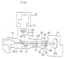
- Referring now to fig. 1 roughly showing one example of an X-ray irradiation apparatus provided with an irradiation range monitor according to the present invention,
reference numeral 11 designates a laser tube as a visible light source emitting a laser beam LB in the visible range,reference numeral 12 designates a beam expander for regulatedly expanding said laser beam LB to form a parallel beam having an appointed diameter, andreference numeral 13 designates a polarizing plate or a filter for regulating the intensity of the laser beam LB. Thesemembers 11 to 13 are housed in ahousing 10 in a coaxial manner. -
Reference numeral 14 designates an X-ray projector, such as an X-ray tube, disposed at right angles with respect to the laser tube 11 (laser LB), andreference numeral 15 designates an X-ray guide tube disposed so as to meet at almost right angles with the projecting direction of the laser beam LB and almost horizontally in a line for guiding an X-ray beam (XB) emitted from saidX-ray projector 14. Said X-rayguide tube 15 is formed of for example of glass or metal and is provided with a thin passage therewithin for converging the X-ray XB so that its diameter may amount to about 10 microns. In addition,reference numeral 16 designates a holder member suitably disposed for holding theX-ray guide tube 15. -
Reference numeral 17 designates a mirror disposed between theX-ray projector 14 and a focusinglens 19. The reflecting surface 17A of themirror 17 is adapted to form a predetermined angle α (for example, the angle α in the drawing is 45°) with the longitudinal direction of the X-ray guide tube 15 (hereinafter referred to as X-ray irradiation axis and shown by a mark J) for reflecting the laser beam LB incident at an angle of about 90° relative to said X-ray irradiation axis J by 90° to form a parallel laser beam LB′ along the X-ray irradiation axis J. Saidmirror 17 is provided with anopening 18 formed nearly at the center thereof for inserting theX-ray guide tube 15 therethrough. - The focusing
lens 19 is formed of for example a convex lens disposed in the vicinity of the pointed end of theX-ray guide tube 15, and is provided with anopening 20 formed nearly at the center thereof for inserting theX-ray guide tube 15 thereinto. The optical axis of the focusinglens 19 is parallel to the X-ray irradiation axis J. - In addition, the above described
mirror 17 and focusinglens 19 are independently provided with an alignment mechanism (not shown). -
Reference numeral 21 designates an object to be subjected to the application of X-rays. Theobject 21 is disposed at the focal position of said focusinglens 19 and held by a holder (not shown) in such a manner that it is movable in all directions, that is, back and forth, up and down and right and left, and that the angle of the incident surface relative to theX-ray guide tube 15 can optionally be set. -
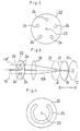
Reference numeral 22 designates a shading member of for example disc shape disposed between themirror 17 and the focusinglens 19, that is, in the vicinity of the focusinglens 19 in the preferred embodiment shown in the drawing, and provided with anopening 23 formed at the center thereof for inserting theX-ray guide tube 15 thereinto and five beam-passing throughholes 24 formed at positions dividing a circle centered to said opening 23 into five equal parts, as shown in fig. 2. - The
housing 10 which houses themembers 11 to 24 is formed for example of iron or lead so as to avoid leakage of X-rays to the outside. - Next, the operation of the X-ray irradiation apparatus provided with an irradiation range monitor having the above described construction will be described below with reference to fig. 3.
- At first, the
laser tube 11, the beam expander 12 and the polarizingplate 13 are aligned so that their optical axes coincide, and themirror 17 and the focusinglens 19 are adjusted by means of the respective alignment mechanisms so that the laser beam LB′ reflected by themirror 17 may be parallel (coaxial) to the X-ray irradiation axis J. - 1. When, under these conditions, the
object 21 is placed for example at a position B in fig. 3 and the distance L between the exposedsurface 21A of theobject 21 and the focusinglens 19 is equal to the focal distance F of the focusinglens 19, the laser beam LB′ reflected from themirror 17 passes through the beam-passing throughholes 24 of theshading member 22 and the focusinglens 19 to form an image shaped as one point on saidsurface 21A, this point-shaped image coinciding with the position where the X-ray beam XB is applied. - 2. When the
object 21 is placed at a position A in fig. 3 and said distance L is shorter than said distance F, said laser beam LB′ passes through the beam-passing throughholes 24 of the shadingmember 22 and the focusinglens 19 and forms an image, which is not reversed in the up and down direction on thesurface 21A. This image consists of five spots corresponding to the arrangement of the beam-passing throughholes 24 in the shadingmember 22. - 3. When the
object 21 is placed at a position C in fig. 3 and said distance L is longer than said distance F, said laser beam LB′ passes through the beam- passing throughholes 24 of the shadingmember 22 and the focusinglens 19 and forms an image, which is reversed in the up and down direction on thesurface 21A. This image consists of five spots in a configuration opposite to the arrangement of the beam-passing throughholes 24 in the shadingmember 22 in the up and down direction. - In the above described cases 2., 3., it is necessary only to move the focusing lens or the
object 21 in the horizontal direction (the direction shown by an arrow XY in fig. 3) by an appropriate distance and make said distance L equal to said distance F. - As shown in the above described preferred embodiment, the shading
member 22 disposed at a position upstream of the focusinglens 19 is provided with the beam-passing throughholes 24 which are not symmetric in the up and down directions, so that an image formed on thesurface 21A by the laser beam LB′, which has passed through the beam-passing throughholes 24 and thecollecting lens 19, is different depending upon the distance L between thesurface 21A of theobject 21 and the focusinglens 19, whereby it can be judged whether the image exists at the focal position of the focusinglens 20 or not. - Under the condition shown in the above described case 1., if the position where the X-ray beam XB is applied to the
surface 21A is identical with the position where the laser BL′ is focused, both said position where the X-ray beam XB is applied to thesurface 21A and said position where the laser beam LB is focused coincide with each other regardless of the change of the angle formed between thesurface 21A and the X-ray irradiation axis J, so that the irradiation range of the X-ray beam XB on thesurface 21A can be monitored by confirming the position where the laser beam LB′ is indicent upon thesurface 21A visually or by means of a telescope and the like, whereby the X-rays XB can be accurately directed upon the desired range of theobject 21. - In addition, according to the above described example, if the laser beam LB′ incident upon the focusing
lens 19 is not parallel to the optical axis of the focusing lens 19 (or vertical to the surface of the lens), the number of the spots formed on thesurface 21A is reduced or the brilliancy is not uniform even though all spots are formed. Thus, the condition of the laser beam LB′ incident upon the focusinglens 19 also can be confirmed. - The present invention is not limited by the above described example. For instance, the beam-passing through holes formed in the shading
member 22 may be formed as one opening 25, which is not symmetrical in the up and down direction (symmetrical in the right and left direction), as shown in fig. 4. - In addition, the above described beam-passing through
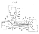
holes 24 and opening 25 may be assymmetrical in the right and left direction or may be assymetric in both the up and down direction and the right and left direction. - Referring to figs. 5,6 showing a different example of the present invention, a member for holding the
X-ray guide tube 15 is used also as the shading member.Reference numeral 30 designates ray guide pipes formed of metal, such as stainless steel or aluminum, or other materials, and held horizontally, theX-ray guide tube 15 being inserted into aspace 31 having a reverse triangular shape as seen in section and formed by piling up the threebeam guide pipes 30 in parallel to each other in a triangular shape as seen in section.Internal spaces 32 of the respectivebeam guide pipes 30 are formed as beam-passing through holes through which pass the laser beam LB′ reflected by themirror 17. - The X-ray irradiation apparatus provided with an irradiation range monitor having the above described construction operates in the same manner as in the above described first example, so that the description of the operation is omitted. The second example shows an advantage in that the
X-ray guide tube 15 can be held more surely and accurately. - In addition, in the above described embodiments, members such as the
laser tube 11, thebeam expander 12 and thepolarizing plate 13 may be housed in a housing pipe mounted in thehousing 10, so that the optical axes of these members may accurately coincide with each other. - In addition, it is not always required to set the angle α formed between the
mirror 17 and the X-ray irradiation axis J at 45°. It goes without saying that every arrangement, in which the laser beam LB′ reflected by themirror 17 becomes coaxial with the X-ray irradiation axis J, can be used. - In addition, it goes without saying that a visible light source emitting visible rays may be used in place of the
laser tube 11. - As described above, the X-ray irradiation apparatus according to the present invention is adapted to make the laser and the X-rays coaxial with each other by means of the mirror and the focusing lens, so that the X-ray irradiation range can be accurately monitored and the X-rays can be accurately applied to the desired range of the object to be subjected to the application of X-rays regardless of the rotating angle of the exposed surface of the object.
- When the shading member provided with the beam-pas sing through holes, which are not symmetrical in the up and down direction or the right and left direction, is provided upstream of the focusing lens in addition to the above described construction, the X-ray irradiation range can be accurately monitored regardless of the rotating angle of the exposed surface of the object, and the position of the exposed surface can be found by observing the configuration of the image formed on this surface by the laser beam, whereby the X-rays can be accurately applied to the desired range of the object by suitably moving the focusing lens or the object on the basis of the observed configuration.
- In particular, the present invention is effective in the case where the X-ray irradiation range on the surface to be subjected to the application of X-rays is small (for example 10 microns in diameter).
Claims (9)
- an X-ray projector (14) for emitting X-rays (XB) toward an object (21),
- a light source (10) for emitting a ray (LB,LB′) of visible light, and
- a mirror (17) disposed between said X-ray projector and said object in an inclined position, so that the light beam (LB) emitted by said light source is reflected (LB′) to be coaxial or nearly coaxial with said X-rays (XB),
characterized by
a focusing lens (19) disposed between said mirror (17) and said object (21) and spaced apart from said object substantially by the focal distance (F) of said collecting lens, and
an X-ray guide tube (15) passing through said mirror (17) and said focusing lens (19) coaxially with the optical axis of said focusing lens and provided with a thin passage for passing therethrough said X-rays (XB).
Applications Claiming Priority (4)
| Application Number | Priority Date | Filing Date | Title |
|---|---|---|---|
| JP11317/88 | 1988-01-20 | ||
| JP1131388A JPH0760199B2 (en) | 1988-01-20 | 1988-01-20 | X-ray irradiation device with irradiation area monitor |
| JP11313/88 | 1988-01-20 | ||
| JP1131788A JPH0760200B2 (en) | 1988-01-20 | 1988-01-20 | X-ray irradiation device with irradiation area monitor |
Publications (3)
| Publication Number | Publication Date |
|---|---|
| EP0325158A2 true EP0325158A2 (en) | 1989-07-26 |
| EP0325158A3 EP0325158A3 (en) | 1990-11-28 |
| EP0325158B1 EP0325158B1 (en) | 1993-08-04 |
Family
ID=26346726
Family Applications (1)
| Application Number | Title | Priority Date | Filing Date |
|---|---|---|---|
| EP89100429A Expired - Lifetime EP0325158B1 (en) | 1988-01-20 | 1989-01-11 | X-ray irradiation apparatus provided with irradiation range monitor |
Country Status (3)
| Country | Link |
|---|---|
| US (1) | US4969177A (en) |
| EP (1) | EP0325158B1 (en) |
| DE (1) | DE68907924T2 (en) |
Cited By (6)
| Publication number | Priority date | Publication date | Assignee | Title |
|---|---|---|---|---|
| EP0318012A2 (en) * | 1987-11-27 | 1989-05-31 | Hitachi, Ltd. | X-ray analyzer |
| FR2760833A1 (en) * | 1997-03-13 | 1998-09-18 | Helmut Fischer Gmbh & Co | METHOD AND DEVICE FOR MEASURING THE THICKNESS OF A THIN LAYER BY X-RAY FLUORESCENCE |
| WO2000042420A1 (en) * | 1998-12-24 | 2000-07-20 | Quanta Vision, Inc. | X-ray inspection device using small-angle diffused radiation and variants |
| FR2806472A1 (en) * | 2000-03-17 | 2001-09-21 | Helmut Fischer Gmbh & Co | METHOD FOR ADJUSTING THE POSITION OF A MEASURING INSTRUMENT WHEN MEASURING LAYER THICKNESS WITH X-FLUORESCENCE |
| EP2079083A2 (en) * | 2008-01-08 | 2009-07-15 | Poskom Co., ltd. | Compact and lightweight x-ray device |
| DE102011105630B4 (en) | 2010-08-31 | 2019-08-22 | Hitachi High-Tech Science Corporation | X-ray fluorescence analyzer and X-ray fluorescence analysis method |
Families Citing this family (7)
| Publication number | Priority date | Publication date | Assignee | Title |
|---|---|---|---|---|
| JPH0390845A (en) * | 1989-09-01 | 1991-04-16 | Hitachi Ltd | Method and apparatus for surface analysis |
| FR2664984B1 (en) * | 1990-07-18 | 1992-09-25 | Snecma | NON - DESTRUCTIVE RADIATION TESTING APPARATUS HAVING A LASER SIGHT. |
| US6502984B2 (en) | 1997-01-17 | 2003-01-07 | Canon Kabushiki Kaisha | Radiographic apparatus |
| JP2002039975A (en) * | 2000-07-27 | 2002-02-06 | Seiko Instruments Inc | Fluorescent x-ray analyzer |
| DE10259696B4 (en) | 2002-12-18 | 2018-07-05 | Immobiliengesellschaft Helmut Fischer Gmbh & Co. Kg | Device for measuring the thickness of thin layers |
| CN105377936B (en) * | 2013-07-31 | 2018-08-24 | 陶氏环球技术有限责任公司 | Structure PU stickers for compound bonding |
| JP6320814B2 (en) * | 2014-03-20 | 2018-05-09 | 株式会社日立ハイテクサイエンス | X-ray analyzer |
Citations (1)
| Publication number | Priority date | Publication date | Assignee | Title |
|---|---|---|---|---|
| JPS58133239A (en) * | 1982-02-02 | 1983-08-08 | 株式会社堀場製作所 | Apparatus for monitoring x-ray irradiated region |
Family Cites Families (1)
| Publication number | Priority date | Publication date | Assignee | Title |
|---|---|---|---|---|
| US3921001A (en) * | 1972-08-21 | 1975-11-18 | Medinova Ab Of Sweden | Screening or aperture device for an x-ray apparatus |
-
1989
- 1989-01-11 DE DE89100429T patent/DE68907924T2/en not_active Expired - Fee Related
- 1989-01-11 EP EP89100429A patent/EP0325158B1/en not_active Expired - Lifetime
- 1989-01-17 US US07/297,759 patent/US4969177A/en not_active Expired - Fee Related
Patent Citations (1)
| Publication number | Priority date | Publication date | Assignee | Title |
|---|---|---|---|---|
| JPS58133239A (en) * | 1982-02-02 | 1983-08-08 | 株式会社堀場製作所 | Apparatus for monitoring x-ray irradiated region |
Non-Patent Citations (1)
| Title |
|---|
| OEFZS BER. No. 4288, WE-327/84, August 1984 Osterreichisches Forschungszentrum Seibersdorf GesmbH K.WALLISCH et al. "Dichte- und Dichteprofilmessungen an H}llschichten von HTR-Brennstoffteilchen " Sep. from: Atomkernenergie. Kerntechnik; vol. 44 (1984), no. 4 * |
Cited By (10)
| Publication number | Priority date | Publication date | Assignee | Title |
|---|---|---|---|---|
| EP0318012A2 (en) * | 1987-11-27 | 1989-05-31 | Hitachi, Ltd. | X-ray analyzer |
| EP0318012A3 (en) * | 1987-11-27 | 1990-05-23 | Hitachi, Ltd. | X-ray analyzer |
| FR2760833A1 (en) * | 1997-03-13 | 1998-09-18 | Helmut Fischer Gmbh & Co | METHOD AND DEVICE FOR MEASURING THE THICKNESS OF A THIN LAYER BY X-RAY FLUORESCENCE |
| US6038280A (en) * | 1997-03-13 | 2000-03-14 | Helmut Fischer Gmbh & Co. Institut Fur Electronik Und Messtechnik | Method and apparatus for measuring the thicknesses of thin layers by means of x-ray fluorescence |
| WO2000042420A1 (en) * | 1998-12-24 | 2000-07-20 | Quanta Vision, Inc. | X-ray inspection device using small-angle diffused radiation and variants |
| FR2806472A1 (en) * | 2000-03-17 | 2001-09-21 | Helmut Fischer Gmbh & Co | METHOD FOR ADJUSTING THE POSITION OF A MEASURING INSTRUMENT WHEN MEASURING LAYER THICKNESS WITH X-FLUORESCENCE |
| EP2079083A2 (en) * | 2008-01-08 | 2009-07-15 | Poskom Co., ltd. | Compact and lightweight x-ray device |
| EP2079083A3 (en) * | 2008-01-08 | 2010-08-18 | Poskom Co., ltd. | Compact and lightweight x-ray device |
| US8011829B2 (en) | 2008-01-08 | 2011-09-06 | Poskom Co., Ltd. | Compact and lightweight X-ray device |
| DE102011105630B4 (en) | 2010-08-31 | 2019-08-22 | Hitachi High-Tech Science Corporation | X-ray fluorescence analyzer and X-ray fluorescence analysis method |
Also Published As
| Publication number | Publication date |
|---|---|
| EP0325158B1 (en) | 1993-08-04 |
| EP0325158A3 (en) | 1990-11-28 |
| DE68907924D1 (en) | 1993-09-09 |
| DE68907924T2 (en) | 1993-11-11 |
| US4969177A (en) | 1990-11-06 |
Similar Documents
| Publication | Publication Date | Title |
|---|---|---|
| EP1238266B1 (en) | Apparatus for shaping an x-ray beam and method of directing an x-ray beam through an aperture | |
| US5803606A (en) | Surface photothermic testing device | |
| EP0325158B1 (en) | X-ray irradiation apparatus provided with irradiation range monitor | |
| US4291938A (en) | Apparatus for dark field illumination | |
| US3893129A (en) | Light beam recording device | |
| DE10309269B4 (en) | Device for Total Internal Reflection Microscopy | |
| JPH10501071A (en) | Automated optical alignment device and method using Raman scattering of capillary contents | |
| JP2001512237A5 (en) | ||
| US6636308B1 (en) | Apparatus for measuring characteristics of optical angle | |
| EP0433613B1 (en) | Microscopic spectrometer with Cassegrain objective | |
| JPS6258140A (en) | Optical analyzer | |
| JP2007524073A (en) | Aiming device and measuring device that can be used without or in contact | |
| US4768878A (en) | Test arrangement for non-contacting identification of defects in non-structured surfaces | |
| JP2580183B2 (en) | Radiation image reader | |
| US5473438A (en) | Spectroscopic method and apparatus for measuring optical radiation | |
| JP3388285B2 (en) | Inspection device | |
| JP3148355B2 (en) | Lighting equipment | |
| WO2007063343A1 (en) | Laser processing tool | |
| JP2995361B2 (en) | X-ray irradiator with irradiation area monitor | |
| JPH04297810A (en) | Optical tester | |
| RU2112209C1 (en) | Device for determination of coating thickness by x-ray-fluorescent method | |
| JPH01185499A (en) | X-ray irradiating device with irradiation area monitor | |
| US4968139A (en) | Illuminating system for the visual inspection of objects | |
| JPH01185500A (en) | X-ray irradiating device with irradiating area monitor | |
| DE4013421A1 (en) | Illumination optics for remission measuring appts. - concentrates light beam from halogen lamp in mantle surfaces and deflects by 45 deg. onto measuring spot |
Legal Events
| Date | Code | Title | Description |
|---|---|---|---|
| PUAI | Public reference made under article 153(3) epc to a published international application that has entered the european phase |
Free format text: ORIGINAL CODE: 0009012 |
|
| AK | Designated contracting states |
Kind code of ref document: A2 Designated state(s): DE FR |
|
| PUAL | Search report despatched |
Free format text: ORIGINAL CODE: 0009013 |
|
| AK | Designated contracting states |
Kind code of ref document: A3 Designated state(s): DE FR |
|
| RHK1 | Main classification (correction) |
Ipc: G01N 23/083 |
|
| 17P | Request for examination filed |
Effective date: 19901201 |
|
| 17Q | First examination report despatched |
Effective date: 19920520 |
|
| GRAA | (expected) grant |
Free format text: ORIGINAL CODE: 0009210 |
|
| AK | Designated contracting states |
Kind code of ref document: B1 Designated state(s): DE FR |
|
| PG25 | Lapsed in a contracting state [announced via postgrant information from national office to epo] |
Ref country code: FR Effective date: 19930804 |
|
| REF | Corresponds to: |
Ref document number: 68907924 Country of ref document: DE Date of ref document: 19930909 |
|
| EN | Fr: translation not filed | ||
| PGFP | Annual fee paid to national office [announced via postgrant information from national office to epo] |
Ref country code: DE Payment date: 19940128 Year of fee payment: 6 |
|
| PLBE | No opposition filed within time limit |
Free format text: ORIGINAL CODE: 0009261 |
|
| STAA | Information on the status of an ep patent application or granted ep patent |
Free format text: STATUS: NO OPPOSITION FILED WITHIN TIME LIMIT |
|
| 26N | No opposition filed | ||
| PG25 | Lapsed in a contracting state [announced via postgrant information from national office to epo] |
Ref country code: DE Effective date: 19951003 |