EP0324257A2 - Liquid transfer assemblies - Google Patents
Liquid transfer assemblies Download PDFInfo
- Publication number
- EP0324257A2 EP0324257A2 EP19880312098 EP88312098A EP0324257A2 EP 0324257 A2 EP0324257 A2 EP 0324257A2 EP 19880312098 EP19880312098 EP 19880312098 EP 88312098 A EP88312098 A EP 88312098A EP 0324257 A2 EP0324257 A2 EP 0324257A2
- Authority
- EP
- European Patent Office
- Prior art keywords
- valve
- syringe
- liquid
- container
- transfer assembly
- Prior art date
- Legal status (The legal status is an assumption and is not a legal conclusion. Google has not performed a legal analysis and makes no representation as to the accuracy of the status listed.)
- Granted
Links
Images
Classifications
-
- A—HUMAN NECESSITIES
- A61—MEDICAL OR VETERINARY SCIENCE; HYGIENE
- A61J—CONTAINERS SPECIALLY ADAPTED FOR MEDICAL OR PHARMACEUTICAL PURPOSES; DEVICES OR METHODS SPECIALLY ADAPTED FOR BRINGING PHARMACEUTICAL PRODUCTS INTO PARTICULAR PHYSICAL OR ADMINISTERING FORMS; DEVICES FOR ADMINISTERING FOOD OR MEDICINES ORALLY; BABY COMFORTERS; DEVICES FOR RECEIVING SPITTLE
- A61J1/00—Containers specially adapted for medical or pharmaceutical purposes
- A61J1/14—Details; Accessories therefor
- A61J1/20—Arrangements for transferring or mixing fluids, e.g. from vial to syringe
- A61J1/2096—Combination of a vial and a syringe for transferring or mixing their contents
-
- A—HUMAN NECESSITIES
- A61—MEDICAL OR VETERINARY SCIENCE; HYGIENE
- A61J—CONTAINERS SPECIALLY ADAPTED FOR MEDICAL OR PHARMACEUTICAL PURPOSES; DEVICES OR METHODS SPECIALLY ADAPTED FOR BRINGING PHARMACEUTICAL PRODUCTS INTO PARTICULAR PHYSICAL OR ADMINISTERING FORMS; DEVICES FOR ADMINISTERING FOOD OR MEDICINES ORALLY; BABY COMFORTERS; DEVICES FOR RECEIVING SPITTLE
- A61J1/00—Containers specially adapted for medical or pharmaceutical purposes
- A61J1/05—Containers specially adapted for medical or pharmaceutical purposes for collecting, storing or administering blood, plasma or medical fluids ; Infusion or perfusion containers
- A61J1/06—Ampoules or carpules
- A61J1/067—Flexible ampoules, the contents of which are expelled by squeezing
-
- A—HUMAN NECESSITIES
- A61—MEDICAL OR VETERINARY SCIENCE; HYGIENE
- A61J—CONTAINERS SPECIALLY ADAPTED FOR MEDICAL OR PHARMACEUTICAL PURPOSES; DEVICES OR METHODS SPECIALLY ADAPTED FOR BRINGING PHARMACEUTICAL PRODUCTS INTO PARTICULAR PHYSICAL OR ADMINISTERING FORMS; DEVICES FOR ADMINISTERING FOOD OR MEDICINES ORALLY; BABY COMFORTERS; DEVICES FOR RECEIVING SPITTLE
- A61J1/00—Containers specially adapted for medical or pharmaceutical purposes
- A61J1/14—Details; Accessories therefor
- A61J1/20—Arrangements for transferring or mixing fluids, e.g. from vial to syringe
- A61J1/2003—Accessories used in combination with means for transfer or mixing of fluids, e.g. for activating fluid flow, separating fluids, filtering fluid or venting
- A61J1/202—Separating means
- A61J1/2037—Separating means having valve means
-
- A—HUMAN NECESSITIES
- A61—MEDICAL OR VETERINARY SCIENCE; HYGIENE
- A61J—CONTAINERS SPECIALLY ADAPTED FOR MEDICAL OR PHARMACEUTICAL PURPOSES; DEVICES OR METHODS SPECIALLY ADAPTED FOR BRINGING PHARMACEUTICAL PRODUCTS INTO PARTICULAR PHYSICAL OR ADMINISTERING FORMS; DEVICES FOR ADMINISTERING FOOD OR MEDICINES ORALLY; BABY COMFORTERS; DEVICES FOR RECEIVING SPITTLE
- A61J2205/00—General identification or selection means
- A61J2205/20—Colour codes
-
- Y—GENERAL TAGGING OF NEW TECHNOLOGICAL DEVELOPMENTS; GENERAL TAGGING OF CROSS-SECTIONAL TECHNOLOGIES SPANNING OVER SEVERAL SECTIONS OF THE IPC; TECHNICAL SUBJECTS COVERED BY FORMER USPC CROSS-REFERENCE ART COLLECTIONS [XRACs] AND DIGESTS
- Y10—TECHNICAL SUBJECTS COVERED BY FORMER USPC
- Y10S—TECHNICAL SUBJECTS COVERED BY FORMER USPC CROSS-REFERENCE ART COLLECTIONS [XRACs] AND DIGESTS
- Y10S128/00—Surgery
- Y10S128/24—Medical-surgical bags
Definitions
- This invention relates to liquid transfer assemblies.
- Previous methods of administering drugs to patients by means of a syringe involves fitting a needle to the syringe, breaking the neck off a glass drug ampoule, inserting the needle into the ampoule, drawing up the drug into the syringe and then injecting the drug in the usual way, after having evacuated air from the syringe.
- breaking the neck of the ampoule can result in glass shards being produced. These can in some case contaminate the contents of the ampoule and may be drawn up into the syringe.
- the shards and the broken parts of the ampoule also present a hazard to the clinician administering the drug by increasing the risk of cutting the skin and allowing contamination of or by the clinician.
- the act of inserting a sharply pointed needle into the narrow severed neck of the ampoule also presents the risk that the user will be pricked by the needle if it is not correctly inserted. Holding the drug ampoule and the syringe barrel whilst withdrawing the syringe plunger requires some manual dexterity and is difficult where the clinician's hands are wet or, in an emergency.
- the glass ampoules require special disposal facilities after use, to avoid injury and contact with unused contents of the ampoules.
- Packaging and transport of the ampoules must be such that they will not be damaged. This can lead to bulky and expensive packaging.
- the ampoules are only suitable for administration of a single dose, leading to wastage and complications where doses of different volumes need to be given. There is also the disadvantage that the drug must be transferred to the syringe immediately after having broken off the ampoule neck if the drug if of a kind that is affected by contact with air.
- a liquid transfer assembly characterised in that the assembly comprises a syringe and a liquid container, that the liquid container comprises a reservoir with a flexible wall and an opening to the reservoir including a valve, that the valve is urged to a normally closed position to prevent liquid leaving the container, that the valve is openable by engagement with the syringe, that the wall is adapted to collapse about the contents of the container as liquid is withdrawn by the syringe such that the internal volume of the container is maintained substantially equal to the volume of liquid in the container, and that the internal surface of the wall is provided with a surface formation arranged such that when opposite sides of the wall contact one another on collapse of the wall, a continuous fluid passage is provided therebetween.
- the wall is preferably of a liquid impermeable polymer.
- the surface formation may be in the form of a vertical channel on the inside of one or both sides of the wall.
- the valve preferably includes a valve member and a spring that urges the valve member outwardly to a sealing position, the valve member being pushed inwardly by engagement with the syringe against the action of the spring to an open position.
- the valve and the syringe preferably have cooperating tapered surfaces which engage in a sealing manner when the syringe is inserted into the valve.
- the container may include a seal across the valve that is ruptured on insertion of the syringe.
- the reservoir may contain a liquid drug.
- the liquid transfer assembly comprises a drug container with a bag or reservoir 1 and a syringe 41.
- the reservoir 1 is made of a liquid impermeable polymer material such as PVC or a plastics laminate, the nature of the polymer material and the wall thickness of the bag 1 being such that the wall is flexible.
- the bag 1 is of oval section and, at its upper end, tapers to form a neck 3 of reduced diameter.
- the bag 1 is moulded with two opposite elongate vertical surface formations in the form of outwardly projecting spines 4 and 5 which form shallow vertical channels internally of the bag.
- valve assembly 10 may be of conventional construction comprising an outer valve housing 11 of generally cylindrical shape and have an annular, outwardly-projecting shoulder 12 which engages the upper end of the neck 3.
- An integral flange 13 projects inwardly about half way along the length of the housing 11, the lower surface of the flange providing a valve seat of the valve.
- a tubular extension 15 having a bore 16 therethrough.
- a movable valve member 18 is located in the housing 11 and is urged outwardly to the upper position shown in Figure 1 by means of a helical spring 19.
- the spring 19 embraces the lower stem 20 of the valve member 18 and is trapped between the extension 15 and an annular shoulder 21 on the valve member.
- the shoulder 21 is located midway along the valve member 18 and supports on its upper surface a sealing washer 22 which engages the underside of the flange 13 on the housing when the valve member is in its natural, upper position.
- the valve member 18 is a solid rod of plastics material and of substantially cylindrical shape.
- the lower end 24 of the valve member is a sliding fit within the bore 16 of the extension 15.
- the bore 16, or the lower part of the valve member 18, is shaped such as to permit liquid flow along the bore, around the outside of the valve member.
- the valve member 18 may be provided with longitudinal grooves 26, as shown in Figure 3.
- the upper end of the valve member 18 is similarly shaped or dimensioned where it passes through the aperture in the flange 13 so that liquid can flow between the flange 13 and the valve member when the sealing washer 22 is clear of the flange.
- the diameter of the upper end of the valve member 18 is smaller than that of the upper part of the valve housing 11 so that liquid is free to flow along the housing, between the housing and the valve member.
- a second annular shoulder 28 on the upper part of valve member 18 is a sliding fit within the upper part of the housing 11. The shoulder 28 is cut away with grooves or other apertures so that fluid is free to flow between the shoulder and the housing.
- the bore 29 in the upper part of the housing 11 has a luer taper to fit the nose 40 of a syringe 41 ( Figure 2) inserted within the valve.
- the container is filled with a drug, medicament or other liquid 50.
- a drug, medicament or other liquid 50 is taken to cover powder suspensions in liquids, gels, pastes or the like which can be withdrawn by suction.
- valve 10 Before use, the valve 10 is in the state shown in Figure 1, that is, with the valve member 18 in an upper position so that the spring 19 applies compression to the washer 22 between the shoulder 21 on the valve member and the flange 13 on the valve housing. This seals the valve closed preventing flow of air into the container and preventing escape of the contents.
- the nose 40 of the syringe 41 When it is desired to withdraw drug from the container, the nose 40 of the syringe 41 is pushed into the luer tapered bore 29 of the valve 10, in the manner shown in Figure 2.
- the lower end of the nose 40 engages the top of the valve member 18 thereby pushing it down inwardly of the housing 11 against the action of the spring 19.
- the nose 40 As the nose 40 is pushed fully down it engages as a luer slip fit in the bore 29 to provide a fluid-tight seal with the valve and hence with the container.
- the valve 10 is opened to allow communication between the syringe 41 and the interior of the bag 1.
- the nose 40 of the syringe 41 is pulled out of the valve 10 thereby allowing the valve member 18 to rise and close the valve.
- the bag 1 is maintained in a collapsed or semi-collapsed state, without the admission of air.
- a needle not shown, can then be pushed onto the nose 40 of the syringe and the drug administered in the usual way.
- the container of the present invention is also easier to handle, since the luer-taper fit of the syringe on the valve can be sufficient to retain the container on the syringe, leaving the user both hands free to hold the syringe barrel and plunger.
- the suction applied during withdrawal of the liquid further improves retention of the container on the syringe.
- the withdrawal of drug from the container of the present invention can be achieved more quickly than from previous glass ampoules. Because air is evacuated from the container, there is reduced risk of air embolism from liquid administered by the syringe.
- the use of the bag of plastics material readily enables it to be coloured so as to identify the nature of the contents, thereby reducing the risk of administration of incorrect drugs.
- the wall of the bag can be made opaque, if required, to reduce exposure of the contents to light.
- a seal rupturable by the syringe, may be applied across the top of the valve housing so that it is readily apparent whether or not the container has been used previously. This seal can also provide a visible guarantee of sterility.
- the bag can be made of various other liquid-impermeable, flexible materials, such as metal foil, and that the bag can have different shapes. Other constructions of valve can also be used.
Abstract
Description
- This invention relates to liquid transfer assemblies.
- Previous methods of administering drugs to patients by means of a syringe involves fitting a needle to the syringe, breaking the neck off a glass drug ampoule, inserting the needle into the ampoule, drawing up the drug into the syringe and then injecting the drug in the usual way, after having evacuated air from the syringe.
- There are many disadvantages with such methods which arise from the use of a glass ampoule to contain the drug.
- For example, breaking the neck of the ampoule can result in glass shards being produced. These can in some case contaminate the contents of the ampoule and may be drawn up into the syringe. The shards and the broken parts of the ampoule also present a hazard to the clinician administering the drug by increasing the risk of cutting the skin and allowing contamination of or by the clinician. The act of inserting a sharply pointed needle into the narrow severed neck of the ampoule also presents the risk that the user will be pricked by the needle if it is not correctly inserted. Holding the drug ampoule and the syringe barrel whilst withdrawing the syringe plunger requires some manual dexterity and is difficult where the clinician's hands are wet or, in an emergency.
- The glass ampoules require special disposal facilities after use, to avoid injury and contact with unused contents of the ampoules. Packaging and transport of the ampoules must be such that they will not be damaged. This can lead to bulky and expensive packaging.
- The ampoules are only suitable for administration of a single dose, leading to wastage and complications where doses of different volumes need to be given. There is also the disadvantage that the drug must be transferred to the syringe immediately after having broken off the ampoule neck if the drug if of a kind that is affected by contact with air.
- It is an object of the present invention to provide an improved liquid container and a method of transferring liquid from such a container.
- According to one aspect of the present invention there is provided a liquid transfer assembly, characterised in that the assembly comprises a syringe and a liquid container, that the liquid container comprises a reservoir with a flexible wall and an opening to the reservoir including a valve, that the valve is urged to a normally closed position to prevent liquid leaving the container, that the valve is openable by engagement with the syringe, that the wall is adapted to collapse about the contents of the container as liquid is withdrawn by the syringe such that the internal volume of the container is maintained substantially equal to the volume of liquid in the container, and that the internal surface of the wall is provided with a surface formation arranged such that when opposite sides of the wall contact one another on collapse of the wall, a continuous fluid passage is provided therebetween.
- The wall is preferably of a liquid impermeable polymer. The surface formation may be in the form of a vertical channel on the inside of one or both sides of the wall. The valve preferably includes a valve member and a spring that urges the valve member outwardly to a sealing position, the valve member being pushed inwardly by engagement with the syringe against the action of the spring to an open position. The valve and the syringe preferably have cooperating tapered surfaces which engage in a sealing manner when the syringe is inserted into the valve.
- The container may include a seal across the valve that is ruptured on insertion of the syringe. The reservoir may contain a liquid drug.
- A liquid transfer assembly including drug container, in accordance with the present invention, will now be described, by way of example, with reference to the accompanying drawings, in which:
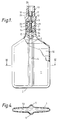
- Figure 1 is a partly sectional side elevation of the container in a closed state;
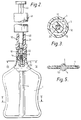
- Figure 2 is a partly sectional side elevation of the assembly during withdrawal of the contents of the container;
- Figure 3 is an enlarged transverse sectional view along the line III - III of Figure 2;
- Figure 4 is a transverse view along the line IV-IV of Figure 1; and
- Figure 5 is a transverse section view along the line V - V of Figure 2.
- With reference first to Figures 1 and 4, the liquid transfer assembly comprises a drug container with a bag or
reservoir 1 and asyringe 41. Thereservoir 1 is made of a liquid impermeable polymer material such as PVC or a plastics laminate, the nature of the polymer material and the wall thickness of thebag 1 being such that the wall is flexible. Thebag 1 is of oval section and, at its upper end, tapers to form aneck 3 of reduced diameter. Thebag 1 is moulded with two opposite elongate vertical surface formations in the form of outwardly projectingspines - Within the
neck 3 of thebag 1 there is sealed a valve assembly indicated by thenumeral 10. Thevalve assembly 10 may be of conventional construction comprising anouter valve housing 11 of generally cylindrical shape and have an annular, outwardly-projectingshoulder 12 which engages the upper end of theneck 3. Anintegral flange 13 projects inwardly about half way along the length of thehousing 11, the lower surface of the flange providing a valve seat of the valve. At thelower end 14 of thehousing 11 there is mounted atubular extension 15 having abore 16 therethrough. - A
movable valve member 18 is located in thehousing 11 and is urged outwardly to the upper position shown in Figure 1 by means of ahelical spring 19. Thespring 19 embraces thelower stem 20 of thevalve member 18 and is trapped between theextension 15 and anannular shoulder 21 on the valve member. Theshoulder 21 is located midway along thevalve member 18 and supports on its upper surface a sealingwasher 22 which engages the underside of theflange 13 on the housing when the valve member is in its natural, upper position. - The
valve member 18 is a solid rod of plastics material and of substantially cylindrical shape. Thelower end 24 of the valve member is a sliding fit within thebore 16 of theextension 15. Thebore 16, or the lower part of thevalve member 18, is shaped such as to permit liquid flow along the bore, around the outside of the valve member. In this respect, thevalve member 18 may be provided withlongitudinal grooves 26, as shown in Figure 3. The upper end of thevalve member 18 is similarly shaped or dimensioned where it passes through the aperture in theflange 13 so that liquid can flow between theflange 13 and the valve member when the sealingwasher 22 is clear of the flange. The diameter of the upper end of thevalve member 18 is smaller than that of the upper part of thevalve housing 11 so that liquid is free to flow along the housing, between the housing and the valve member. A secondannular shoulder 28 on the upper part ofvalve member 18 is a sliding fit within the upper part of thehousing 11. Theshoulder 28 is cut away with grooves or other apertures so that fluid is free to flow between the shoulder and the housing. - The
bore 29 in the upper part of thehousing 11 has a luer taper to fit thenose 40 of a syringe 41 (Figure 2) inserted within the valve. - The container is filled with a drug, medicament or
other liquid 50. In this respect the term 'liquid' is taken to cover powder suspensions in liquids, gels, pastes or the like which can be withdrawn by suction. - Before use, the
valve 10 is in the state shown in Figure 1, that is, with thevalve member 18 in an upper position so that thespring 19 applies compression to thewasher 22 between theshoulder 21 on the valve member and theflange 13 on the valve housing. This seals the valve closed preventing flow of air into the container and preventing escape of the contents. - When it is desired to withdraw drug from the container, the
nose 40 of thesyringe 41 is pushed into the luertapered bore 29 of thevalve 10, in the manner shown in Figure 2. The lower end of thenose 40 engages the top of thevalve member 18 thereby pushing it down inwardly of thehousing 11 against the action of thespring 19. As thenose 40 is pushed fully down it engages as a luer slip fit in thebore 29 to provide a fluid-tight seal with the valve and hence with the container. At the same time, thevalve 10 is opened to allow communication between thesyringe 41 and the interior of thebag 1. - The user then pulls the
plunger 43 of thesyringe 41 outwardly so that suction is applied and thedrug 50 is drawn through thevalve 10 into the syringe. As this happens, the walls of thebag 1 will collapse about its contents so that its internal volume is maintained substantially equal to the volume of liquid contents. This thereby avoids the need to vent the interior of the container which would allow air into contact with the contents. The vertical channels provided by thespines bag 1 even in a partially collapsed state, as shown in Figure 5. - When the desired quantity of
drug 50 has been withdrawn, thenose 40 of thesyringe 41 is pulled out of thevalve 10 thereby allowing thevalve member 18 to rise and close the valve. Thebag 1 is maintained in a collapsed or semi-collapsed state, without the admission of air. - A needle, not shown, can then be pushed onto the
nose 40 of the syringe and the drug administered in the usual way. - Where the
drug 50 has not been fully removed from the container, it is possible to remove further quantities at a later time. - By using a valve that can be opened by the nose of a syringe, the risk of injury by broken glass and needle pricks is removed. Disposal of used containers is also rendered safer. Wastage can be reduce because it may be possible to withdraw fluid from the container several times. The flexible nature of the bag makes it easier to pack and transport without damage. The risk of spillage from open containers is also reduced, this is especially advantageous for cytotoxic drugs for chemotherapy.
- The container of the present invention is also easier to handle, since the luer-taper fit of the syringe on the valve can be sufficient to retain the container on the syringe, leaving the user both hands free to hold the syringe barrel and plunger. The suction applied during withdrawal of the liquid further improves retention of the container on the syringe.
- The withdrawal of drug from the container of the present invention can be achieved more quickly than from previous glass ampoules. Because air is evacuated from the container, there is reduced risk of air embolism from liquid administered by the syringe.
- In place of the moulded
spines - The use of the bag of plastics material readily enables it to be coloured so as to identify the nature of the contents, thereby reducing the risk of administration of incorrect drugs. The wall of the bag can be made opaque, if required, to reduce exposure of the contents to light.
- A seal, rupturable by the syringe, may be applied across the top of the valve housing so that it is readily apparent whether or not the container has been used previously. This seal can also provide a visible guarantee of sterility.
- It will be appreciated that the bag can be made of various other liquid-impermeable, flexible materials, such as metal foil, and that the bag can have different shapes. Other constructions of valve can also be used.
- Where two liquids need to be mixed prior to transfer, they can be supplied in respective containers of the kind described above and coupled together by means of a double-ended male coupling piece. Each end of the coupling piece would open the valve in the respective container allowing liquid to be squeezed out of one container into the other and then back again. Repeated squeezing of the containers mixes their contents so that the mixed liquid can be transfered from either container, after removal of the coupling piece, by using a syringe as described as above.
Claims (8)
Priority Applications (1)
| Application Number | Priority Date | Filing Date | Title |
|---|---|---|---|
| AT88312098T ATE76278T1 (en) | 1988-01-09 | 1988-12-21 | TRANSFER DEVICE FOR LIQUIDS. |
Applications Claiming Priority (2)
| Application Number | Priority Date | Filing Date | Title |
|---|---|---|---|
| GB8800448A GB8800448D0 (en) | 1988-01-09 | 1988-01-09 | Liquid containers |
| GB8800448 | 1988-01-09 |
Publications (3)
| Publication Number | Publication Date |
|---|---|
| EP0324257A2 true EP0324257A2 (en) | 1989-07-19 |
| EP0324257A3 EP0324257A3 (en) | 1989-10-18 |
| EP0324257B1 EP0324257B1 (en) | 1992-05-20 |
Family
ID=10629714
Family Applications (1)
| Application Number | Title | Priority Date | Filing Date |
|---|---|---|---|
| EP19880312098 Expired - Lifetime EP0324257B1 (en) | 1988-01-09 | 1988-12-21 | Liquid transfer assemblies |
Country Status (6)
| Country | Link |
|---|---|
| US (1) | US5006118A (en) |
| EP (1) | EP0324257B1 (en) |
| JP (1) | JPH024374A (en) |
| AT (1) | ATE76278T1 (en) |
| DE (1) | DE3871362D1 (en) |
| GB (2) | GB8800448D0 (en) |
Cited By (8)
| Publication number | Priority date | Publication date | Assignee | Title |
|---|---|---|---|---|
| EP0706406A4 (en) * | 1993-07-02 | 1997-01-08 | Barry Farris | Method and apparatus for loading needleless syringes |
| WO1998034582A1 (en) * | 1997-02-07 | 1998-08-13 | Visionary Medical Products, Inc. | Needle-less fluid transfer device and method |
| EP0798990A4 (en) * | 1994-12-21 | 1998-11-25 | Alan L Roitman | Needleless transfer system |
| EP0882441A3 (en) * | 1997-06-03 | 1999-02-24 | TAKEDA CHEMICAL INDUSTRIES, Ltd. | Dual-chamber injection system and connector used therefor |
| WO2000016729A1 (en) * | 1998-09-22 | 2000-03-30 | Fresenius Kabi Ab | Container for intravenous administration |
| FR2859625A1 (en) * | 2003-09-11 | 2005-03-18 | Christiane Cinqualbre | Medicine preparing bag, has watertight envelope with internal volume, in which one part of volume includes dosage space with series of additive stocks that are released into solution in another part of volume to prepare medicine |
| US6918418B1 (en) | 2000-03-13 | 2005-07-19 | Barry Farris | Method and apparatus for the storage and transfer of a lyophilisate |
| US6997352B2 (en) * | 2000-09-15 | 2006-02-14 | Brightwell Dispensers Limited | Liquid dispenser assembly |
Families Citing this family (43)
| Publication number | Priority date | Publication date | Assignee | Title |
|---|---|---|---|---|
| EP0462255B1 (en) * | 1990-01-08 | 1994-09-21 | Becton Dickinson France S.A. | Two-compartment storage and transfer flask |
| DE4230645C2 (en) * | 1992-09-12 | 1996-03-07 | Bernd Hansen | ampoule |
| US5339511A (en) * | 1993-04-20 | 1994-08-23 | Bell Margaret A | Method for screwing medication vials to IV-bags |
| US6068011A (en) | 1993-10-13 | 2000-05-30 | Paradis; Joseph R. | Control of fluid flow |
| US5549577A (en) * | 1993-12-29 | 1996-08-27 | Ivac Corporation | Needleless connector |
| US5429256A (en) * | 1994-01-24 | 1995-07-04 | Kestenbaum; Alan D. | Drug withdrawal system for container |
| US5620434A (en) * | 1994-03-14 | 1997-04-15 | Brony; Seth K. | Medicine vial link for needleless syringes |
| US5871110A (en) * | 1996-09-13 | 1999-02-16 | Grimard; Jean-Pierre | Transfer assembly for a medicament container having a splashless valve |
| US5873872A (en) * | 1996-09-17 | 1999-02-23 | Becton Dickinson And Company | Multipositional resealable vial connector assembly for efficient transfer of liquid |
| US6321909B1 (en) * | 1997-02-13 | 2001-11-27 | Sky High, Llc | System for storing polyethylene glycol solutions |
| US5957898A (en) | 1997-05-20 | 1999-09-28 | Baxter International Inc. | Needleless connector |
| ATE335518T1 (en) | 1997-05-20 | 2006-09-15 | Baxter Int | NEEDLELESS COUPLING PIECE |
| DE19723197C2 (en) * | 1997-06-03 | 1999-07-29 | Braun Melsungen Ag | Suction device for body fluids |
| US5984912A (en) * | 1997-07-25 | 1999-11-16 | Brocco Diagnostics, Inc. | Collapsible medical bag for the containment and delivery of diagnostic contrast media and parenteral drug formulations |
| US5925029A (en) * | 1997-09-25 | 1999-07-20 | Becton, Dickinson And Company | Method and apparatus for fixing a connector assembly onto a vial with a crimp cap |
| US6090093A (en) * | 1997-09-25 | 2000-07-18 | Becton Dickinson And Company | Connector assembly for a vial having a flexible collar |
| US6213994B1 (en) | 1997-09-25 | 2001-04-10 | Becton Dickinson France, S.A. | Method and apparatus for fixing a connector assembly onto a vial |
| US6681946B1 (en) * | 1998-02-26 | 2004-01-27 | Becton, Dickinson And Company | Resealable medical transfer set |
| US6382442B1 (en) | 1998-04-20 | 2002-05-07 | Becton Dickinson And Company | Plastic closure for vials and other medical containers |
| US6003566A (en) | 1998-02-26 | 1999-12-21 | Becton Dickinson And Company | Vial transferset and method |
| US6209738B1 (en) | 1998-04-20 | 2001-04-03 | Becton, Dickinson And Company | Transfer set for vials and medical containers |
| US6957745B2 (en) * | 1998-04-20 | 2005-10-25 | Becton, Dickinson And Company | Transfer set |
| US6378714B1 (en) | 1998-04-20 | 2002-04-30 | Becton Dickinson And Company | Transferset for vials and other medical containers |
| US6904662B2 (en) * | 1998-04-20 | 2005-06-14 | Becton, Dickinson And Company | Method of sealing a cartridge or other medical container with a plastic closure |
| US6053888A (en) * | 1998-08-05 | 2000-04-25 | Kong; Carl Cheung Tung | Variable volume bottle and related medical fluid infusion system |
| US6308747B1 (en) | 1998-10-01 | 2001-10-30 | Barry Farris | Needleless method and apparatus for transferring liquid from a container to an injecting device without ambient air contamination |
| US6296150B1 (en) | 1999-02-25 | 2001-10-02 | Barry Farris | Medicinal dosing apparatus and method |
| US6379342B1 (en) * | 1999-04-02 | 2002-04-30 | Scion International, Inc. | Ampoule for dispensing medication and method of use |
| US6908459B2 (en) * | 2001-12-07 | 2005-06-21 | Becton, Dickinson And Company | Needleless luer access connector |
| US20060081242A1 (en) * | 2004-09-15 | 2006-04-20 | Tai-Kang Han | Portable air pre-treating device for medical treatment |
| FR2905429A1 (en) * | 2006-09-04 | 2008-03-07 | Debiotech Sa | DEVICE FOR DELIVERING A LIQUID COMPRISING A PUMP AND A VALVE |
| US20080283143A1 (en) * | 2007-05-17 | 2008-11-20 | Mckibbin Travis | Liquid dispenser apparatus |
| JP6290625B2 (en) * | 2011-01-17 | 2018-03-07 | アクティヴパック, インコーポレイテッド | Aseptic cartridge and dispensing device |
| GB2504289A (en) * | 2012-07-24 | 2014-01-29 | Rifat Jan | Paste dispenser and paste receiving pouches |
| FR3004087B1 (en) * | 2013-04-08 | 2015-05-15 | Oreal | PACKAGING DEVICE FOR A COSMETIC PRODUCT, IN PARTICULAR FOR A COSMETIC DEGASTING PRODUCT |
| WO2015064737A1 (en) * | 2013-10-31 | 2015-05-07 | 大和製罐株式会社 | Syringe container |
| DE102014008611A1 (en) * | 2014-06-06 | 2015-12-17 | Kocher-Plastik Maschinenbau Gmbh | container |
| DE102014220365A1 (en) * | 2014-10-08 | 2016-04-28 | Vetter Pharma-Fertigung GmbH & Co. KG | System and method for preparing an injection |
| CA2973083A1 (en) * | 2015-01-07 | 2016-07-14 | Dr. Py Institute Llc | Pouch with sealed fitment and method |
| US11027960B2 (en) | 2015-08-13 | 2021-06-08 | David G. Kraenzle | Apparatus, systems, and methods relating to transfer of liquids to/from containers and/or storage of liquids in containers |
| US10005654B2 (en) | 2015-08-13 | 2018-06-26 | David G. Kraenzle | Apparatus, systems, and methods relating to transfer of fluids to/from containers and/or storage/transport of fluids in containers |
| WO2017039432A1 (en) * | 2015-08-28 | 2017-03-09 | N.V. Nutricia | Collapsible bottle |
| DE102022001757A1 (en) * | 2022-05-19 | 2023-11-23 | Kocher-Plastik Maschinenbau Gmbh | container |
Citations (6)
| Publication number | Priority date | Publication date | Assignee | Title |
|---|---|---|---|---|
| FR1413164A (en) * | 1964-08-24 | 1965-10-08 | Egema | Process for the emission of a plurality of products, such as pharmaceutical, cosmetic and other products, and packaging which can be used for carrying out this process |
| FR2233245A1 (en) * | 1973-06-12 | 1975-01-10 | Rhone Poulenc Sa | Flexible bag reservoirs with partially preformed walls - thus defining a passage for accepting fittings |
| US4230112A (en) * | 1978-08-07 | 1980-10-28 | Smith Philip E | Syringe-type liquid container dispenser adapter |
| US4493348A (en) * | 1981-06-29 | 1985-01-15 | Pur/Acc Corporation | Method and apparatus for orally dispensing liquid medication |
| EP0156500A1 (en) * | 1984-02-24 | 1985-10-02 | Scholle Corporation | Fluid dispensing assembly |
| EP0158612A2 (en) * | 1983-12-23 | 1985-10-16 | Bengt Gustavsson | A volume variable vessel |
Family Cites Families (11)
| Publication number | Priority date | Publication date | Assignee | Title |
|---|---|---|---|---|
| US1534913A (en) * | 1923-11-10 | 1925-04-21 | Eugene C Buck | Serum extractor |
| GB1192986A (en) * | 1967-08-31 | 1970-05-28 | Eschmann Bros & Walsh Ltd | Intravenous Valve Assembly |
| ES370617A1 (en) * | 1968-08-28 | 1971-05-01 | Pfizer | Dual-chamber liquid ejector and filling connector |
| US3853157A (en) * | 1973-02-22 | 1974-12-10 | A Madaio | Process and apparatus for dispensing liquid compositions intended for parenteral administration |
| US3806086A (en) * | 1973-03-15 | 1974-04-23 | Nosco Plastics | Automatic shut-off valve for administration of sterile fluids |
| US3921630A (en) * | 1974-02-26 | 1975-11-25 | American Hospital Supply Corp | Thermoplastic bottle with controlled lateral collapse and method of dispensing liquid therefrom |
| US4443219A (en) * | 1981-03-10 | 1984-04-17 | C. R. Bard, Inc. | System for aseptically draining a urine bag |
| US4553970A (en) * | 1983-12-28 | 1985-11-19 | Miles Laboratories, Inc. | Collapsible molded container |
| US4709734A (en) * | 1985-04-17 | 1987-12-01 | The Coca-Cola Company | Method and system for filling packages with a carbonated beverage pre-mix under micro-gravity conditions |
| ATE80548T1 (en) * | 1985-06-14 | 1992-10-15 | Shinsozai Sogo Kenkyusho Kk | MEDICAL LIQUID CONTAINER AND ITS MANUFACTURE. |
| US4838875A (en) * | 1987-12-09 | 1989-06-13 | Somor Andrew T | Method and apparatus for dealing with intravenous fluids |
-
1988
- 1988-01-09 GB GB8800448A patent/GB8800448D0/en active Pending
- 1988-12-21 EP EP19880312098 patent/EP0324257B1/en not_active Expired - Lifetime
- 1988-12-21 AT AT88312098T patent/ATE76278T1/en not_active IP Right Cessation
- 1988-12-21 DE DE8888312098T patent/DE3871362D1/en not_active Expired - Fee Related
- 1988-12-21 GB GB8829762A patent/GB2213458B/en not_active Expired - Fee Related
-
1989
- 1989-01-09 JP JP1001411A patent/JPH024374A/en active Pending
- 1989-01-09 US US07/294,703 patent/US5006118A/en not_active Expired - Fee Related
Patent Citations (6)
| Publication number | Priority date | Publication date | Assignee | Title |
|---|---|---|---|---|
| FR1413164A (en) * | 1964-08-24 | 1965-10-08 | Egema | Process for the emission of a plurality of products, such as pharmaceutical, cosmetic and other products, and packaging which can be used for carrying out this process |
| FR2233245A1 (en) * | 1973-06-12 | 1975-01-10 | Rhone Poulenc Sa | Flexible bag reservoirs with partially preformed walls - thus defining a passage for accepting fittings |
| US4230112A (en) * | 1978-08-07 | 1980-10-28 | Smith Philip E | Syringe-type liquid container dispenser adapter |
| US4493348A (en) * | 1981-06-29 | 1985-01-15 | Pur/Acc Corporation | Method and apparatus for orally dispensing liquid medication |
| EP0158612A2 (en) * | 1983-12-23 | 1985-10-16 | Bengt Gustavsson | A volume variable vessel |
| EP0156500A1 (en) * | 1984-02-24 | 1985-10-02 | Scholle Corporation | Fluid dispensing assembly |
Cited By (11)
| Publication number | Priority date | Publication date | Assignee | Title |
|---|---|---|---|---|
| EP0706406A4 (en) * | 1993-07-02 | 1997-01-08 | Barry Farris | Method and apparatus for loading needleless syringes |
| EP0798990A4 (en) * | 1994-12-21 | 1998-11-25 | Alan L Roitman | Needleless transfer system |
| WO1998034582A1 (en) * | 1997-02-07 | 1998-08-13 | Visionary Medical Products, Inc. | Needle-less fluid transfer device and method |
| EP0882441A3 (en) * | 1997-06-03 | 1999-02-24 | TAKEDA CHEMICAL INDUSTRIES, Ltd. | Dual-chamber injection system and connector used therefor |
| WO2000016729A1 (en) * | 1998-09-22 | 2000-03-30 | Fresenius Kabi Ab | Container for intravenous administration |
| US6796971B2 (en) | 1998-09-22 | 2004-09-28 | Fresenius Kabi Ab | Container for intravenous administration |
| CZ300605B6 (en) * | 1998-09-22 | 2009-06-24 | Fresenius Kabi Ab | Device for storing and administering medical fluids |
| US6918418B1 (en) | 2000-03-13 | 2005-07-19 | Barry Farris | Method and apparatus for the storage and transfer of a lyophilisate |
| US6997352B2 (en) * | 2000-09-15 | 2006-02-14 | Brightwell Dispensers Limited | Liquid dispenser assembly |
| FR2859625A1 (en) * | 2003-09-11 | 2005-03-18 | Christiane Cinqualbre | Medicine preparing bag, has watertight envelope with internal volume, in which one part of volume includes dosage space with series of additive stocks that are released into solution in another part of volume to prepare medicine |
| WO2005025482A1 (en) * | 2003-09-11 | 2005-03-24 | Christiane Cinqualbre | Flexible container for the extemporaneous preparation or administration and the administration of a liquid product, such as a solute intended for use as a medicament |
Also Published As
| Publication number | Publication date |
|---|---|
| EP0324257A3 (en) | 1989-10-18 |
| DE3871362D1 (en) | 1992-06-25 |
| GB2213458A (en) | 1989-08-16 |
| GB8829762D0 (en) | 1989-02-15 |
| US5006118A (en) | 1991-04-09 |
| GB2213458B (en) | 1991-05-01 |
| JPH024374A (en) | 1990-01-09 |
| ATE76278T1 (en) | 1992-06-15 |
| GB8800448D0 (en) | 1988-02-10 |
| EP0324257B1 (en) | 1992-05-20 |
Similar Documents
| Publication | Publication Date | Title |
|---|---|---|
| EP0324257B1 (en) | Liquid transfer assemblies | |
| US6228065B1 (en) | Displacement activated medical check valve | |
| US4392850A (en) | In-line transfer unit | |
| US4392851A (en) | In-line transfer unit | |
| US3729031A (en) | Liquid dispenser and plunger and method and apparatus for filling same | |
| US3938520A (en) | Transfer unit having a dual channel transfer member | |
| US4493348A (en) | Method and apparatus for orally dispensing liquid medication | |
| US4532969A (en) | Fluid withdrawal and instillation device | |
| US5232029A (en) | Additive device for vial | |
| US5454409A (en) | Transfer adaptors | |
| US4505709A (en) | Liquid transfer device | |
| US3788524A (en) | Additive container | |
| CA1046462A (en) | Flexible medical fluid container having a combined fill and administration port and reinforced hanger | |
| US5067948A (en) | Safety, packaging, injection and disposal system for pre-filled pharmaceutical vials | |
| AU720748B2 (en) | Container closure system | |
| EP0817654B1 (en) | Pre-filled syringe drug delivery system | |
| EP1029526B1 (en) | Medicament container stopper with integral spike access means | |
| EP0088056B1 (en) | Filled unit dose container | |
| US4146153A (en) | Sterile dispensing device | |
| EP0567510B1 (en) | Plastic syringe | |
| US4775376A (en) | Method and apparatus for catching fluids purged from a syringe | |
| JPS63197463A (en) | Liquid sample extraction or injection apparatus | |
| US3630199A (en) | Unitized injection system | |
| JPS62253069A (en) | Substance handling apparatus and method | |
| JP2004520111A (en) | Ampules for packaging and transferring liquids or powders for medical use |
Legal Events
| Date | Code | Title | Description |
|---|---|---|---|
| PUAI | Public reference made under article 153(3) epc to a published international application that has entered the european phase |
Free format text: ORIGINAL CODE: 0009012 |
|
| AK | Designated contracting states |
Kind code of ref document: A2 Designated state(s): AT BE CH DE ES FR GR IT LI LU NL SE |
|
| PUAL | Search report despatched |
Free format text: ORIGINAL CODE: 0009013 |
|
| AK | Designated contracting states |
Kind code of ref document: A3 Designated state(s): AT BE CH DE ES FR GR IT LI LU NL SE |
|
| 17P | Request for examination filed |
Effective date: 19900207 |
|
| 17Q | First examination report despatched |
Effective date: 19910415 |
|
| ITF | It: translation for a ep patent filed |
Owner name: ING. ZINI MARANESI & C. S.R.L. |
|
| GRAA | (expected) grant |
Free format text: ORIGINAL CODE: 0009210 |
|
| AK | Designated contracting states |
Kind code of ref document: B1 Designated state(s): AT BE CH DE ES FR GR IT LI LU NL SE |
|
| PG25 | Lapsed in a contracting state [announced via postgrant information from national office to epo] |
Ref country code: SE Effective date: 19920520 Ref country code: NL Effective date: 19920520 Ref country code: LI Effective date: 19920520 Ref country code: GR Free format text: LAPSE BECAUSE OF FAILURE TO SUBMIT A TRANSLATION OF THE DESCRIPTION OR TO PAY THE FEE WITHIN THE PRESCRIBED TIME-LIMIT Effective date: 19920520 Ref country code: ES Free format text: THE PATENT HAS BEEN ANNULLED BY A DECISION OF A NATIONAL AUTHORITY Effective date: 19920520 Ref country code: CH Effective date: 19920520 Ref country code: BE Effective date: 19920520 Ref country code: AT Effective date: 19920520 |
|
| REF | Corresponds to: |
Ref document number: 76278 Country of ref document: AT Date of ref document: 19920615 Kind code of ref document: T |
|
| REF | Corresponds to: |
Ref document number: 3871362 Country of ref document: DE Date of ref document: 19920625 |
|
| REG | Reference to a national code |
Ref country code: CH Ref legal event code: PL |
|
| ET | Fr: translation filed | ||
| NLV1 | Nl: lapsed or annulled due to failure to fulfill the requirements of art. 29p and 29m of the patents act | ||
| PG25 | Lapsed in a contracting state [announced via postgrant information from national office to epo] |
Ref country code: LU Free format text: LAPSE BECAUSE OF NON-PAYMENT OF DUE FEES Effective date: 19921231 |
|
| PGFP | Annual fee paid to national office [announced via postgrant information from national office to epo] |
Ref country code: DE Payment date: 19930202 Year of fee payment: 5 |
|
| PLBE | No opposition filed within time limit |
Free format text: ORIGINAL CODE: 0009261 |
|
| STAA | Information on the status of an ep patent application or granted ep patent |
Free format text: STATUS: NO OPPOSITION FILED WITHIN TIME LIMIT |
|
| 26N | No opposition filed | ||
| PG25 | Lapsed in a contracting state [announced via postgrant information from national office to epo] |
Ref country code: FR Effective date: 19930831 |
|
| REG | Reference to a national code |
Ref country code: FR Ref legal event code: ST |
|
| PG25 | Lapsed in a contracting state [announced via postgrant information from national office to epo] |
Ref country code: DE Effective date: 19940901 |
|
| PG25 | Lapsed in a contracting state [announced via postgrant information from national office to epo] |
Ref country code: IT Free format text: LAPSE BECAUSE OF NON-PAYMENT OF DUE FEES;WARNING: LAPSES OF ITALIAN PATENTS WITH EFFECTIVE DATE BEFORE 2007 MAY HAVE OCCURRED AT ANY TIME BEFORE 2007. THE CORRECT EFFECTIVE DATE MAY BE DIFFERENT FROM THE ONE RECORDED. Effective date: 20051221 |