EP0323261B1 - Ink jet recording apparatus - Google Patents
Ink jet recording apparatus Download PDFInfo
- Publication number
- EP0323261B1 EP0323261B1 EP88312417A EP88312417A EP0323261B1 EP 0323261 B1 EP0323261 B1 EP 0323261B1 EP 88312417 A EP88312417 A EP 88312417A EP 88312417 A EP88312417 A EP 88312417A EP 0323261 B1 EP0323261 B1 EP 0323261B1
- Authority
- EP
- European Patent Office
- Prior art keywords
- cleaning
- recording head
- cleaning member
- blade
- sub
- Prior art date
- Legal status (The legal status is an assumption and is not a legal conclusion. Google has not performed a legal analysis and makes no representation as to the accuracy of the status listed.)
- Expired - Lifetime
Links
Images


Classifications
-
- B—PERFORMING OPERATIONS; TRANSPORTING
- B41—PRINTING; LINING MACHINES; TYPEWRITERS; STAMPS
- B41J—TYPEWRITERS; SELECTIVE PRINTING MECHANISMS, i.e. MECHANISMS PRINTING OTHERWISE THAN FROM A FORME; CORRECTION OF TYPOGRAPHICAL ERRORS
- B41J2/00—Typewriters or selective printing mechanisms characterised by the printing or marking process for which they are designed
- B41J2/005—Typewriters or selective printing mechanisms characterised by the printing or marking process for which they are designed characterised by bringing liquid or particles selectively into contact with a printing material
- B41J2/01—Ink jet
- B41J2/135—Nozzles
- B41J2/165—Preventing or detecting of nozzle clogging, e.g. cleaning, capping or moistening for nozzles
- B41J2/16517—Cleaning of print head nozzles
- B41J2/16535—Cleaning of print head nozzles using wiping constructions
- B41J2/16538—Cleaning of print head nozzles using wiping constructions with brushes or wiper blades perpendicular to the nozzle plate
Definitions
- the present invention relates to an ink jet recording apparatus, and more particularly to an ink jet recording apparatus equipped with cleaning means for eliminating ink, water droplets etc. deposited on the ink discharging face of the recording head.
- the ink jet recording apparatus there may result dewing in the vicinity of the ink discharging apertures, for example on a surface in which said apertures are provided, depending on the temperature and other conditions of the recording head and surrounding atmosphere, due to a high moisture condition generated by the evaporation of the water contained in the ink and recording medium.
- the ink discharging surface may be wetted by the ink bouncing back from the recording medium.
- Such dewing or wetting phenomenon becomes more marked in case a fixing heater is employed for accelerating the fixation of the recorded image to the recording medium, or in case of a high dot duty ratio.
- Such dewing or wetting causes uneven deposition of the water droplets on the ink discharging surface, thus unevenly pulling the discharged ink droplets and giving rise to fluctuations in the discharging direction, discharging speed or particle size thereof, thereby eventually deteriorating the quality of the obtained image.
- the wetting of the ink discharging surface facilitates deposition of paper powder or dust, thus deteriorating the quality of the recorded image.
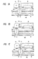
- Figs. 1A to 1C are schematic plan views of a conventional example of wiping means utilizing a blade member composed of silicon rubber or butyl rubber, suitable as the cleaning means.
- a recording head 20 positioned opposite to the recording surface of a recording medium 33, such as paper sheet or plastic sheet, and provided with nozzles for ink discharge.
- a carriage 16 supporting said recording head 20 is connected to a part of a driving belt 18 and is slidably supported by mutually parallel two guide shaft 19A, 19B, so that the recording head 20 can reciprocate over the entire width of the recording sheet 33.
- a discharge recovery device 26 for the recording head is provided at a position opposite to an end of the moving path of the recording head 20, for example the home position thereof. Said discharge recovery device 26 is activated by an unrepresented motor and a transmission mechanism, thereby capping the recording head 20.
- Said discharge recovery device 26 is activated by an unrepresented motor and a transmission mechanism, thereby capping the recording head 20.
- ink suction by suitable suction means provided in the discharge recovery device 26, or ink pressurizing by suitable pressurizing means provided in the ink supply path to the recording head 20, thereby forcedly eliminating viscous ink from the discharge apertures, thus achieving discharge recovery.
- said capping protects the discharge apertures of the recording head, for example after a recording operation is terminated.
- the blade 31 is uniformly supported on both sides, with a cantilever mechanism, by a blade support member 31A, and is moved by an unrepresented motor and a transmission mechanism as in the head recovery device 26, thereby being capable of engaging with the ink discharging surface of the recording head 20.
- the blade 31 is made to protrude into the moving path of the recording head 20 at a suitable timing during the recording operation of the recording head 20 or after the discharge recovery operation by the recovery device 26, thereby wiping off the ink droplets, water droplets or other foreign matters on the ink discharge surface of the head 20 in the reciprocating motion thereof.
- Fig. 1A shows a case in which the recording head 20 moves in a direction A towards the home position after the recording operation, and the head recovery device 26 and the blade 31 are in a state retracted from the moving path of the recording head 20.
- Fig. 1B shows a state in which the recording head 20 is stopped at the home position, and the capping member 26A of the head recovery device 26 engages with the ink discharging surface of the head 20, achieving by a movement of said capping member 26A in a direction B.
- the blade 31 moves with the head recovery device 26, but does not move with respect to the device 26.
- Fig. 1C shows a case in which the recording head 20 in a direction D, from the home position to the recording start position, and the capping member 26A of the head recovery device 26 is retracted from the moving path of the recording head 20.
- the blade 31 moves in a direction C, with respect to the recovery device 26, thus protruding into the moving path of the recording head 20. Therefore the ink discharging surface of the recording head 20 contacts the blade member 31 and is thus cleaned.
- the wiping operation by the blade member 31 removes the dewing on the ink discharging surface or the wetting thereof generated by the ink rebounced from the recording medium.
- German Laid-open Patent DE 3611666A1 proposes a method of fixing the blade in a protruding state in the moving path of the recording head at a predetermined position, for example in the vicinity of the home position, and achieving the cleaning operation by the movement of the recording head.
- the ink discharging surface of the recording head is usually subjected to a surface treatment for achieving uniform wettability for ink, namely water-repellent surface treatment for aqueous ink, or oil-repellent surface treatment for oily ink, thereby minimizing ink deposition on the ink discharging surface.
- an object of the present invention to provide an ink jet recording apparatus capable of minimizing the deterioration in the surface characteristic caused by the abrasion of the ink discharging surface resulting from the cleaning operation and simplifying the cleaning mechanism, by eliminating the protruding and retracting operations of the cleaning member.
- Figs. 2A to 2C are plan views of an ink jet recording apparatus constituting a first embodiment of the present invention, showing cleaning operations similar to those shown in Figs. 1A to 1C, wherein same components as those in Figs. 1A to 1C are represented by same numbers and will not be explained further.
- Figs. 3A - 3C, 4A - 4C and 5A - 5C are also similar drawings.
- the wiping means which is one of preferable cleaning means, is composed of a wiping blade 31 constituting a cleaning member, of which an end is pinched by a blade support member 31A and a blade length regulating member 31B and fixed in a cantilever structure.
- the blade length regulating member 31B composed for example of hard rubber, plastics or metal, is positioned on the side of the recording medium 33 with respect to the blade 31, and extends along the blade 31 to the middle thereof. Due to the presence of the wiping force regulating means, the length of the bendable arm of the blade 31 varies according to the direction of bending.
- the blade 31 composed of silicone rubber has a thickness 0.1 to 0.5 mm, and a protruding length X (from the blade support member 31A to the front end of the blade 31) of 5 - 10 mm, while the protruding amount Y (from the blade support member 31A to the front end of the regulating member) is 2 - 6 mm, with an overlapping length of the head and blade of 0.5 to 1.5 mm, but other suitable dimensional ranges may be adopted.
- the ratio Y/X is preferably equal to 0.2 or higher in consideration of the durability, more preferably in further consideration of 0.5 or higher, and most preferably 0.7 or higher.
- the upper limit of said ratio is preferably a value giving a large value of X - Y, preferably about 0.95, in consideration of the thickness of the blade.
- the blade support member 31A is fixed to the head recovery device 26.
- Fig. 2A shows a state in which the recording head 20 moves in a direction A toward the home position, for example after a recording operation.
- the capping member 26A of the head recovery device 26 is retracted from the moving path of the recording head 20, but the blade 31 fixedly protrudes in said moving path.
- the ink discharging surface of the recording head 20 comes into contact with the wiping blade 31, but the contacting force is very weak, as the regulating member 31B does not function.
- Fig. 2B shows a state in which the recording head 20 is stopped at the home position, and the capping member 26A of the head recovery device 26 effects a capping operation in contact with the ink discharging surface of the head 20, as the result of movement of said capping member 26A in a direction B.
- Fig. 2C shows a case in which the recording head 20 moves from the home position to the recording start position, in a direction D, wherein the discharge recovery device 26 and.the blade 31 are in positions same as in Fig. 2A. Therefore, also in this movement, the ink discharging surface of the recording head 20 is wiped.
- the wiping force in Fig. 2A is different from that in Fig. 2C, as the practical arm length of the blade 31 varies depending on the wiping direction. More specifically, the wiping force is weak in the movement toward the home position, but is strong enough for removing the dewing etc. in the movement toward the recording start position.
- Such wiping operation is not limited to the reciprocating motion for the discharge recovery by the discharge recovery device 26, but may naturally be conducted in a reciprocating motion exclusive for such wiping, to be conducted at a predetermined timing, for example after continuous recording operation of a predetermined period.
- Figs. 3A to 3C are plan views of an ink jet recording apparatus constituting a second embodiment of the present invention, wherein wiping means is employed as cleaning means as in Figs. 1A to 1C.
- a blade support member 31A is fixed to the head recovery device 26, and a blade 31 is supported by the blade support member 31A in a similar manner as in Figs. 1A to 1C.
- the present embodiment is different from the structure shown in Figs. 1A to 1C in that the blade 31 is provided with notches at the side closer to the recording medium 33, whereby the blade 31 has different bending rigidity according to the bending direction, thus being capable of regulating the wiping force.
- Figs. 3A to 3C show wiping operations respectively corresponding to those in Figs. 1A to 1C, whereby the wiping force is weak in case of the movement of the recording head 20 toward the home position but is strong enough for removing the ink droplets, water droplets and other matters in the movement toward the recording start position.
- the regulating means is composed of notches provided on the blade, but there may also be employed a blade having surface irregularities on one surface for showing different bending rigidity on both sides, or a blade composed of mutually adhered plural members of different elastic moduli.
- Figs. 4A to 4C are plan views of an ink jet recording apparatus constituting a third embodiment of the present invention, employing wiping means as the cleaning means as in Figs. 2A to 2C and 3A to 3C.
- a blade support member 31A is fixed to the head recovery device 26, and a blade 31 is supported by the blade support member 31A in a similar manner as in Figs. 1A to 1C.
- the blade support member 31A has an arm for supporting the blade 31, inclined toward the head recovery device 26.
- the angle ⁇ of inclination can be suitably selected and such regulating means for the wiping force causes to vary the bending of the blade 31, in the wiping of the ink discharging surface of the recording head 20, depending on the wiping direction.
- Figs. 5A to 5C are plan views of an ink jet recording apparatus constituting a fourth embodiment of the present invention, employing wiping means as the cleaning means as in Figs. 2A - 2C, 3A - 3C and 4A - 4C.
- a blade support member 31A and its extention is rotatably supported, at the middle thereof, by a fulcrum member 31C fixed to the head recovery device 26. Also an end of said blade support member 31A, opposite to the end thereof supporting the blade 31, is connected to an end of a spring 31E of which the other end is connected to the head recovery device 26, whereby a part of the blade support member 31A engages with a stopper 31D fixed to the head recovery device 26.
- a state shown in Fig. 4B is realized when the blade 31 does not wipe the ink emitting surface.
- Such regulating means for the wiping force causes the wiping force of the blade 31 to vary depending on the direction of wiping.
- the wiping force is weak in the movement of the recording head 20 toward the home position, but is strong enough for removing dews and so on in the movement toward the recording start position.
- the recording medium is not smeared by the ink scattering, since the wiping operation in the movement from the recording position toward the home position is conducted with a weak force.
- the position of the blade is not limited to that in the foregoing embodiments but may be suitably selected in the moving path of the recording head.
- the cleaning member may be composed of plural sheet-shaped blades or a brush-like member.
- the structure employing a plate-shaped elastic blade positioned corresponding to the direction of arrangement of the discharged apertures, as described above, is preferably in exhibiting excellent cleaning (wiping) effect, and the regulating means is most effective for such cleaning blade.
- the regulating means for the wiping force in the present invention collectively includes means capable of varying the wiping force depending on the direction of wiping. Consequently it is not limited to means for controlling and varying the wiping force by respective structure, but is subject to various modifications within the scope of the present invention.
- Said regulating means in each embodiment can be designed in such a manner that the ratio of cleaning force in different moving directions of the recording head (ratio of smaller force to larger force) is equal to 0.2 or larger, preferably 0.5 or larger and more preferably 0.7 or larger.
- the recording head to be employed in the ink jet recording apparatus of the present invention is preferably based on a method of image formation with ink, utilizing thermal energy generated by an electrothermal converting element for forming ink droplets, in consideration of ease of formation of a planar discharging surface and each of cleaning even in an array of plural discharge apertures.
- Such recording head being compact, low in manufacturing cost and capable of providing high image quality, is preferably employed in a form having an ink tank containing ink and being detachable from the carriage.
- the present invention varies the cleaning force on the ink discharging surface of the recording head depending on the direction of cleaning (relative movement of the recording head and the cleaning member), whereby the cleaning is conducted in a direction with a force enough for removing the dewing, wetting or dusts but in the other direction with an extremely weak force.
- the apparatus can be simplified as the operation of causing the cleaning member to protrude in or retracting from the moving path of the recording head, and the mechanism therefor, can be dispensed with.
- the abrasion of the ink discharging surface can be minimized since the contact between the cleaning member and the ink discharging surface is weak except in the removal of the ink droplets, water droplets caused by dewing or other foreign matters.
Description
- The present invention relates to an ink jet recording apparatus, and more particularly to an ink jet recording apparatus equipped with cleaning means for eliminating ink, water droplets etc. deposited on the ink discharging face of the recording head.
- In the ink jet recording apparatus, there may result dewing in the vicinity of the ink discharging apertures, for example on a surface in which said apertures are provided, depending on the temperature and other conditions of the recording head and surrounding atmosphere, due to a high moisture condition generated by the evaporation of the water contained in the ink and recording medium.
- Also the ink discharging surface may be wetted by the ink bouncing back from the recording medium.
- Such dewing or wetting phenomenon becomes more marked in case a fixing heater is employed for accelerating the fixation of the recorded image to the recording medium, or in case of a high dot duty ratio.
- Such dewing or wetting causes uneven deposition of the water droplets on the ink discharging surface, thus unevenly pulling the discharged ink droplets and giving rise to fluctuations in the discharging direction, discharging speed or particle size thereof, thereby eventually deteriorating the quality of the obtained image. Also the wetting of the ink discharging surface facilitates deposition of paper powder or dust, thus deteriorating the quality of the recorded image.
- As a countermeasure for such phenomenon, there has been conducted cleaning of the ink discharging surface at suitable timing, in order to remove such dewing or wetting. A wiping mechanism utilizing a blade as the cleaning means is disclosed in the U.S.P. No. 4,364,065.
- Figs. 1A to 1C are schematic plan views of a conventional example of wiping means utilizing a blade member composed of silicon rubber or butyl rubber, suitable as the cleaning means.
- In these drawings there is shown a
recording head 20 positioned opposite to the recording surface of arecording medium 33, such as paper sheet or plastic sheet, and provided with nozzles for ink discharge. Acarriage 16 supporting said recordinghead 20 is connected to a part of adriving belt 18 and is slidably supported by mutually parallel twoguide shaft recording head 20 can reciprocate over the entire width of therecording sheet 33. - A
discharge recovery device 26 for the recording head is provided at a position opposite to an end of the moving path of therecording head 20, for example the home position thereof. Saiddischarge recovery device 26 is activated by an unrepresented motor and a transmission mechanism, thereby capping therecording head 20. In combination with the capping of therecording head 20 with acap member 26A of saiddischarge recovery device 26, there is conducted ink suction by suitable suction means provided in thedischarge recovery device 26, or ink pressurizing by suitable pressurizing means provided in the ink supply path to therecording head 20, thereby forcedly eliminating viscous ink from the discharge apertures, thus achieving discharge recovery. Also said capping protects the discharge apertures of the recording head, for example after a recording operation is terminated. - A
blade 31, constituting cleaning (wiping) member and composed for example of silicone rubber, is positioned at a side of thehead recovery device 26. Theblade 31 is uniformly supported on both sides, with a cantilever mechanism, by ablade support member 31A, and is moved by an unrepresented motor and a transmission mechanism as in thehead recovery device 26, thereby being capable of engaging with the ink discharging surface of therecording head 20. Theblade 31 is made to protrude into the moving path of therecording head 20 at a suitable timing during the recording operation of therecording head 20 or after the discharge recovery operation by therecovery device 26, thereby wiping off the ink droplets, water droplets or other foreign matters on the ink discharge surface of thehead 20 in the reciprocating motion thereof. - In the following there will be explained the wiping operation based on the above-explained structure.
- Fig. 1A shows a case in which the
recording head 20 moves in a direction A towards the home position after the recording operation, and thehead recovery device 26 and theblade 31 are in a state retracted from the moving path of therecording head 20. - Fig. 1B shows a state in which the
recording head 20 is stopped at the home position, and thecapping member 26A of thehead recovery device 26 engages with the ink discharging surface of thehead 20, achieving by a movement of said cappingmember 26A in a direction B. Theblade 31 moves with thehead recovery device 26, but does not move with respect to thedevice 26. - Fig. 1C shows a case in which the
recording head 20 in a direction D, from the home position to the recording start position, and thecapping member 26A of thehead recovery device 26 is retracted from the moving path of therecording head 20. On the other hand, theblade 31 moves in a direction C, with respect to therecovery device 26, thus protruding into the moving path of therecording head 20. Therefore the ink discharging surface of therecording head 20 contacts theblade member 31 and is thus cleaned. - The wiping operation by the
blade member 31 removes the dewing on the ink discharging surface or the wetting thereof generated by the ink rebounced from the recording medium. - However, in such conventional structure, there are required complicated operations of causing the blade member to protrude in the moving path of the recording head and thereafter retracting said blade member, and complex mechanisms therefor.
- Thus the German Laid-open Patent DE 3611666A1 proposes a method of fixing the blade in a protruding state in the moving path of the recording head at a predetermined position, for example in the vicinity of the home position, and achieving the cleaning operation by the movement of the recording head.
- After having repeated the experiments with the ink jet recording apparatus employing the above-explained method, the inventors found that the recorded image was disturbed after prolonged use.
- Further experiments revealed that this phenomenon was principally due to a change in the state of the ink discharging surface caused by the contact between said surface and the blade.
- More specifically, the ink discharging surface of the recording head is usually subjected to a surface treatment for achieving uniform wettability for ink, namely water-repellent surface treatment for aqueous ink, or oil-repellent surface treatment for oily ink, thereby minimizing ink deposition on the ink discharging surface.
- When thus treated surface layer (ink-repellent treated) is deteriorated in function by the contact with the blade, there will result defective ink discharge, leading to disturbance in the image.
- In consideration of the foregoing, it is an object of the present invention to provide an ink jet recording apparatus capable of minimizing the deterioration in the surface characteristic caused by the abrasion of the ink discharging surface resulting from the cleaning operation and simplifying the cleaning mechanism, by eliminating the protruding and retracting operations of the cleaning member.
- It is an another object of the present invention to provide an ink jet recording apparatus provided with a cleaning member for cleaning the vicinity of the ink discharging apertures of the recording head, and regulating means for varying the cleaning force of the cleaning member according to the direction of wiping.
- It is a still another object of the present invention to provide an ink jet recording apparatus capable of varying the wiping force on the ink discharging surface of the recording head according to the direction of wiping, thereby eliminating the dewing, wetting or dusts in wiping in a predetermined direction but effecting the wiping operation with a lower force in the other direction to avoid undesirable influence on the surface treatment layer of the ink discharging surface.
-
- Figs. 1A to 1C are schematic plan views showing cleaning operation with a conventional cleaning mechanism in an ink jet recording apparatus;
- Figs. 2A to 2C are schematic plan views showing cleaning operation with a cleaning mechanism constituting a first embodiment of the present invention;
- Figs. 3A to 3C are schematic plan views showing cleaning operation with a cleaning mechanism constituting a second embodiment of the present invention;
- Figs. 4A to 4C are schematic plan views showing cleaning operation with a cleaning mechanism constituting a third embodiment of the present invention; and
- Figs. 5A to 5C are schematic plan views showing cleaning operation with a cleaning mechanism constituting a fourth embodiment of the present invention.
- Now the present invention will be clarified in detail by preferred embodiments thereof shown in the attached drawings. However, the present invention is not limited to such embodiments but is subject to variations as long as the objects of the present invention can be achieved.
- Figs. 2A to 2C are plan views of an ink jet recording apparatus constituting a first embodiment of the present invention, showing cleaning operations similar to those shown in Figs. 1A to 1C, wherein same components as those in Figs. 1A to 1C are represented by same numbers and will not be explained further. Figs. 3A - 3C, 4A - 4C and 5A - 5C are also similar drawings.
- In Figs. 2A to 2C, the wiping means, which is one of preferable cleaning means, is composed of a
wiping blade 31 constituting a cleaning member, of which an end is pinched by ablade support member 31A and a bladelength regulating member 31B and fixed in a cantilever structure. In said structure, the bladelength regulating member 31B, composed for example of hard rubber, plastics or metal, is positioned on the side of therecording medium 33 with respect to theblade 31, and extends along theblade 31 to the middle thereof. Due to the presence of the wiping force regulating means, the length of the bendable arm of theblade 31 varies according to the direction of bending. In the present embodiment, theblade 31 composed of silicone rubber has a thickness 0.1 to 0.5 mm, and a protruding length X (from theblade support member 31A to the front end of the blade 31) of 5 - 10 mm, while the protruding amount Y (from theblade support member 31A to the front end of the regulating member) is 2 - 6 mm, with an overlapping length of the head and blade of 0.5 to 1.5 mm, but other suitable dimensional ranges may be adopted. - However, it is experimentally confirmed that the ratio Y/X is preferably equal to 0.2 or higher in consideration of the durability, more preferably in further consideration of 0.5 or higher, and most preferably 0.7 or higher. Also the upper limit of said ratio is preferably a value giving a large value of X - Y, preferably about 0.95, in consideration of the thickness of the blade.
- The
blade support member 31A is fixed to thehead recovery device 26. - Fig. 2A shows a state in which the
recording head 20 moves in a direction A toward the home position, for example after a recording operation. The cappingmember 26A of thehead recovery device 26 is retracted from the moving path of therecording head 20, but theblade 31 fixedly protrudes in said moving path. Thus the ink discharging surface of therecording head 20 comes into contact with thewiping blade 31, but the contacting force is very weak, as the regulatingmember 31B does not function. - Fig. 2B shows a state in which the
recording head 20 is stopped at the home position, and the cappingmember 26A of thehead recovery device 26 effects a capping operation in contact with the ink discharging surface of thehead 20, as the result of movement of said cappingmember 26A in a direction B. - Fig. 2C shows a case in which the
recording head 20 moves from the home position to the recording start position, in a direction D, wherein thedischarge recovery device 26 and.theblade 31 are in positions same as in Fig. 2A. Therefore, also in this movement, the ink discharging surface of therecording head 20 is wiped. - In this state the displacement of the
blade 31 in the direction D is limited by the regulatingmember 31B to reinforce the elastic force of theblade 31, whereby the ink droplets, water droplets and other matters on the ink discharging surface can be securely removed. - In this manner, the wiping force in Fig. 2A is different from that in Fig. 2C, as the practical arm length of the
blade 31 varies depending on the wiping direction. More specifically, the wiping force is weak in the movement toward the home position, but is strong enough for removing the dewing etc. in the movement toward the recording start position. - Such wiping operation is not limited to the reciprocating motion for the discharge recovery by the
discharge recovery device 26, but may naturally be conducted in a reciprocating motion exclusive for such wiping, to be conducted at a predetermined timing, for example after continuous recording operation of a predetermined period. - Figs. 3A to 3C are plan views of an ink jet recording apparatus constituting a second embodiment of the present invention, wherein wiping means is employed as cleaning means as in Figs. 1A to 1C.
- In Figs. 3A to 3C, a
blade support member 31A is fixed to thehead recovery device 26, and ablade 31 is supported by theblade support member 31A in a similar manner as in Figs. 1A to 1C. The present embodiment is different from the structure shown in Figs. 1A to 1C in that theblade 31 is provided with notches at the side closer to therecording medium 33, whereby theblade 31 has different bending rigidity according to the bending direction, thus being capable of regulating the wiping force. - Figs. 3A to 3C show wiping operations respectively corresponding to those in Figs. 1A to 1C, whereby the wiping force is weak in case of the movement of the
recording head 20 toward the home position but is strong enough for removing the ink droplets, water droplets and other matters in the movement toward the recording start position. - In the present embodiment, the regulating means is composed of notches provided on the blade, but there may also be employed a blade having surface irregularities on one surface for showing different bending rigidity on both sides, or a blade composed of mutually adhered plural members of different elastic moduli.
- Figs. 4A to 4C are plan views of an ink jet recording apparatus constituting a third embodiment of the present invention, employing wiping means as the cleaning means as in Figs. 2A to 2C and 3A to 3C.
- In Figs. 4A to 4C, a
blade support member 31A is fixed to thehead recovery device 26, and ablade 31 is supported by theblade support member 31A in a similar manner as in Figs. 1A to 1C. Theblade support member 31A has an arm for supporting theblade 31, inclined toward thehead recovery device 26. The angle ϑ of inclination can be suitably selected and such regulating means for the wiping force causes to vary the bending of theblade 31, in the wiping of the ink discharging surface of therecording head 20, depending on the wiping direction. - Figs. 5A to 5C are plan views of an ink jet recording apparatus constituting a fourth embodiment of the present invention, employing wiping means as the cleaning means as in Figs. 2A - 2C, 3A - 3C and 4A - 4C.
- In Figs. 5A to 5C, a
blade support member 31A and its extention is rotatably supported, at the middle thereof, by afulcrum member 31C fixed to thehead recovery device 26. Also an end of saidblade support member 31A, opposite to the end thereof supporting theblade 31, is connected to an end of aspring 31E of which the other end is connected to thehead recovery device 26, whereby a part of theblade support member 31A engages with astopper 31D fixed to thehead recovery device 26. Thus, a state shown in Fig. 4B is realized when theblade 31 does not wipe the ink emitting surface. Such regulating means for the wiping force causes the wiping force of theblade 31 to vary depending on the direction of wiping. - In the structures shown in Figs. 2A - 2C, 3A - 3C, 4A - 4C and 5A - 5C, the wiping force is weak in the movement of the
recording head 20 toward the home position, but is strong enough for removing dews and so on in the movement toward the recording start position. - In the foregoing embodiments, the recording medium is not smeared by the ink scattering, since the wiping operation in the movement from the recording position toward the home position is conducted with a weak force.
- The position of the blade is not limited to that in the foregoing embodiments but may be suitably selected in the moving path of the recording head.
- In the foregoing explanation there has been employed so-called blade constituting wiping means which is one example of cleaning means excellent in removing effect for ink and other substances, but the present invention is not limited to such blade and is applicable to any means capable of cleaning the ink discharging surface. More specifically, the cleaning member may be composed of plural sheet-shaped blades or a brush-like member.
- However, the structure employing a plate-shaped elastic blade positioned corresponding to the direction of arrangement of the discharged apertures, as described above, is preferably in exhibiting excellent cleaning (wiping) effect, and the regulating means is most effective for such cleaning blade.
- The regulating means for the wiping force in the present invention collectively includes means capable of varying the wiping force depending on the direction of wiping. Consequently it is not limited to means for controlling and varying the wiping force by respective structure, but is subject to various modifications within the scope of the present invention. Said regulating means in each embodiment can be designed in such a manner that the ratio of cleaning force in different moving directions of the recording head (ratio of smaller force to larger force) is equal to 0.2 or larger, preferably 0.5 or larger and more preferably 0.7 or larger.
- The recording head to be employed in the ink jet recording apparatus of the present invention is preferably based on a method of image formation with ink, utilizing thermal energy generated by an electrothermal converting element for forming ink droplets, in consideration of ease of formation of a planar discharging surface and each of cleaning even in an array of plural discharge apertures.
- Such recording head, being compact, low in manufacturing cost and capable of providing high image quality, is preferably employed in a form having an ink tank containing ink and being detachable from the carriage.
- As detailedly explained in the foregoing, the present invention varies the cleaning force on the ink discharging surface of the recording head depending on the direction of cleaning (relative movement of the recording head and the cleaning member), whereby the cleaning is conducted in a direction with a force enough for removing the dewing, wetting or dusts but in the other direction with an extremely weak force.
- Thus the apparatus can be simplified as the operation of causing the cleaning member to protrude in or retracting from the moving path of the recording head, and the mechanism therefor, can be dispensed with.
- Also the abrasion of the ink discharging surface can be minimized since the contact between the cleaning member and the ink discharging surface is weak except in the removal of the ink droplets, water droplets caused by dewing or other foreign matters.
- It is therefore possible to achieve enough cleaning with a simple structure, thereby providing stable recording quality.
Claims (20)
- An ink jet recording apparatus having a recording head (20) and a cleaning member (31) arranged to wipe the recording head (20) on relative movement therebetween in different directions (A,D);
which apparatus is characterised in that:
the cleaning member (31) is arranged so that the force that it exerts on the recording head (20) differs depending upon the direction of the relative movement (A,D). - Apparatus as claimed in claim 1;
a sub-assembly thereof including said cleaning member,
a cleaning unit therefor including said cleaning member, or
a cleaning member therefor,
wherein said cleaning member (31) comprises a wiping blade which is of elastic material and is differentially flexible for said two directions of relative motion (A,D). - Apparatus, sub-assembly, cleaning unit, or cleaning member as claimed in claim 2, wherein said cleaning member is notched to provide said differential flexibility.
- Apparatus as claimed in claim 1, a sub-assembly thereof including said cleaning member, or a cleaning unit therefor including said cleaning member, comprising:
force changing means (31B; - ; 31A; 31C to 31E) co-operative with the cleaning member (31) for changing the force exerted by the cleaning member (31) on the recording head (20) in dependance upon the direction of said relative movement (A,D). - Apparatus, sub-assembly, or cleaning unit as claimed in claim 4 wherein said cleaning member (31) comprises a wiping blade of elastic material.
- Apparatus, sub-assembly, or cleaning unit as claimed in claim 5 wherein the cleaning member (31) and the force changing means (31B) are co-operable to change the effective flexible length of the cleaning member (31) for changing the force exerted by the cleaning member (31) on the recording head (20).
- Apparatus, sub-assembly, or cleaning unit as claimed in claim 6 wherein the cleaning means (31) is pivoted at one end fixed to a blade support member (31A) and said force changing means comprises a blade length regulating member (31B) arranged adjacent to one side of the cleaning member (31).
- Apparatus, sub-assembly, or cleaning unit as claimed in claim 7 wherein:
the cleaning member wiping blade (31) is a plate-like silicone rubber elastic member having a thickness of 0.1 to 0.5 mm, and having a protruding length X measured from the blade support member (31A) to the free end of the blade (31) of between 5 and 10 mm inclusive, which length is sufficient to overlap the recording head by a free length of between 0.5 to 1.5 mm;
the length Y of the regulating member (31B) measured from the blade support member (31) to the free end of the regulating member (31B) is of between 2 and 6 mm inclusive; and
a lengths ratio Y/X is equal to 0.2 or higher. - Apparatus, sub-assembly, or cleaning unit as claimed in claim 8 wherein said lengths ratio Y/X is not less than 0.5.
- Apparatus, sub-assembly, or cleaning unit as claimed in claim 9 wherein said lengths ratio Y/X is not less than 0.7.
- Apparatus, sub-assembly, or cleaning unit as claimed in claim 5 wherein the cleaning member (31) is mounted by a blade support member (31A) and is arranged thereby so that it shall be offset from the normal to the surface of the recording head by an angle ϑ of inclination such that the force exerted by the cleaning member (31) shall vary for each of the directions of relative movement (A,D).
- Apparatus, sub-assembly, or cleaning unit as claimed in claim 5 wherein the cleaning member (31) is rotatably pivoted by means of a fulcrum member (31C) and said force changing means comprises restraint means (31D,31E) co-operable with the cleaning member (31) for controlling the cleaning member to exert different force for each direction of relative movement A,D.
- Apparatus, sub-assembly, or cleaning unit as claimed in claim 12 wherein said restraint means (31D and 31E) comprises a stop (31D) and a spring (31E).
- Apparatus as claimed in claim 1 wherein the recording head surface has a discharge port for discharging ink.
- Apparatus as claimed in claim 14 wherein:
said recording head (20) is mounted by means of a reciprocally movable carriage (16) which is movable by driving means (18) between a recording position and a non-recording position; and
said cleaning member (31) comprises a wiping blade locatable at said non-recording position for wiping clean the recording head surface when said cleaning member (31) and said recording head (20) are moved reciprocally. - Apparatus as claimed in either of claims 14 or 15 wherein said discharge port is provided at a substantially planar portion of the recording head surface.
- Apparatus as claimed in claim 16 wherein in the vicinity of said discharge port the recording head surface is ink repellant.
- Apparatus as claimed in any one of the preceding claims comprising means for forming ink droplets by thermal energy for recording an image with ink.
- Apparatus as claimed in any one of the preceding claims 1 to 17 wherein said recording head (20) has an electrothermal transducer for generating thermal energy.
- Apparatus as claimed in claim 15 or in any claims depending therefrom wherein said recording head (20) has an ink tank for containing ink therein and is integrally and detachably loaded onto said carriage (16).
Applications Claiming Priority (2)
| Application Number | Priority Date | Filing Date | Title |
|---|---|---|---|
| JP335367/87 | 1987-12-29 | ||
| JP62335367A JP2527774B2 (en) | 1987-12-29 | 1987-12-29 | Ink jet recording device |
Publications (3)
| Publication Number | Publication Date |
|---|---|
| EP0323261A2 EP0323261A2 (en) | 1989-07-05 |
| EP0323261A3 EP0323261A3 (en) | 1990-05-02 |
| EP0323261B1 true EP0323261B1 (en) | 1993-09-22 |
Family
ID=18287739
Family Applications (1)
| Application Number | Title | Priority Date | Filing Date |
|---|---|---|---|
| EP88312417A Expired - Lifetime EP0323261B1 (en) | 1987-12-29 | 1988-12-29 | Ink jet recording apparatus |
Country Status (4)
| Country | Link |
|---|---|
| US (1) | US4959673A (en) |
| EP (1) | EP0323261B1 (en) |
| JP (1) | JP2527774B2 (en) |
| DE (1) | DE3884368T2 (en) |
Families Citing this family (45)
| Publication number | Priority date | Publication date | Assignee | Title |
|---|---|---|---|---|
| DE69031666T2 (en) * | 1989-01-13 | 1998-04-02 | Canon Kk | Ink jet recording head, ink jet recording device and wiping method therefor |
| US5689293A (en) * | 1989-01-23 | 1997-11-18 | Canon Kabushiki Kaisha | Ink jet head capping device |
| JPH0347754A (en) * | 1989-04-26 | 1991-02-28 | Canon Inc | Ink jet recorder |
| US6000778A (en) * | 1989-05-18 | 1999-12-14 | Canon Kabushiki Kaisha | Recording apparatus recovery method using variable pressure |
| US5266974A (en) * | 1989-05-18 | 1993-11-30 | Canon Kabushiki Kaisha | Ink jet recording apparatus including means for controlling speed of wiper member |
| JPH0326546U (en) * | 1989-07-25 | 1991-03-18 | ||
| JP2801409B2 (en) * | 1989-12-26 | 1998-09-21 | キヤノン株式会社 | Inkjet device and recording unit cartridge |
| EP0435276B1 (en) * | 1989-12-26 | 1996-07-03 | Canon Kabushiki Kaisha | Ink jet apparatus and recording unit cartridge |
| US5115250A (en) * | 1990-01-12 | 1992-05-19 | Hewlett-Packard Company | Wiper for ink-jet printhead |
| US5471230A (en) * | 1990-02-13 | 1995-11-28 | Canon Kabushiki Kaisha | Capping means and ink jet recording apparatus using the same |
| JP2667277B2 (en) | 1990-03-14 | 1997-10-27 | キヤノン株式会社 | Ink jet recording device |
| US5103244A (en) * | 1990-07-05 | 1992-04-07 | Hewlett-Packard Company | Method and apparatus for cleaning ink-jet printheads |
| US5548309A (en) * | 1990-08-03 | 1996-08-20 | Canon Kabushiki Kaisha | Apparatus and method for wiping an ink jet recording head with control of relative speed between wiper and head |
| US5138334A (en) * | 1990-11-05 | 1992-08-11 | Xerox Corporation | Pneumatic surface cleaning method and apparatus for ink jet printheads |
| JP2944767B2 (en) * | 1991-02-06 | 1999-09-06 | キヤノン株式会社 | Ink jet recording device |
| US5184147A (en) * | 1991-04-22 | 1993-02-02 | Tektronix, Inc. | Ink jet print head maintenance system |
| SG46707A1 (en) * | 1991-05-15 | 1998-02-20 | Seiko Epson Corp | Ink jet type recording apparatus and method of cleaning a recording head |
| US5151715A (en) * | 1991-07-30 | 1992-09-29 | Hewlett-Packard Company | Printhead wiper for ink-jet printers |
| JP3165722B2 (en) * | 1992-01-20 | 2001-05-14 | キヤノン株式会社 | Ink jet device |
| JP3110151B2 (en) * | 1992-04-14 | 2000-11-20 | キヤノン株式会社 | Ink jet recording device |
| EP0585854B1 (en) * | 1992-08-31 | 1998-11-11 | Canon Kabushiki Kaisha | Ink jet head manufacturing method using ion machining and ink jet head manufactured thereby |
| US5644347A (en) * | 1992-09-21 | 1997-07-01 | Hewlett-Packard Company | Inkjet printer with variable wiping capabilities for multiple printheads |
| US5434605A (en) * | 1992-09-21 | 1995-07-18 | Hewlett-Packard Company | Automatic failure recovery method and system for ink-jet printheads |
| US5602573A (en) * | 1993-04-30 | 1997-02-11 | Hewlett-Packard Company | Service station for inkjet printer having wipers with concave wiping edges |
| US5587729A (en) * | 1993-05-11 | 1996-12-24 | Hewlett-Packard Company | Rotatable service station for ink-jet printer |
| US5606354A (en) * | 1993-07-06 | 1997-02-25 | Canon Kabushiki Kaisha | Recovery mechanism for adjustable ink jet head |
| US5489927A (en) * | 1993-08-30 | 1996-02-06 | Hewlett-Packard Company | Wiper for ink jet printers |
| US5559539A (en) * | 1993-10-12 | 1996-09-24 | Dataproducts Corporation | Ink jet recording apparatus having self aligning print head cleaning system and method of operating the print head cleaning system |
| JP3530621B2 (en) * | 1994-04-08 | 2004-05-24 | キヤノン株式会社 | Recovery device and ink jet recording apparatus provided with the recovery device |
| JP3247545B2 (en) * | 1994-06-24 | 2002-01-15 | キヤノン株式会社 | Ink jet recording device |
| JP3322291B2 (en) * | 1994-08-11 | 2002-09-09 | セイコーエプソン株式会社 | Ink jet recording device |
| US5640182A (en) * | 1994-10-24 | 1997-06-17 | Lexmark International, Inc. | Universal ink-jet printhead maintenance station |
| US5627574A (en) * | 1995-01-04 | 1997-05-06 | Brother International Corporation | Maintenance device in an ink jet printing apparatus |
| US5570117A (en) * | 1995-01-06 | 1996-10-29 | Tektronix, Inc. | Print head maintenance method and apparatus with retractable wiper |
| US5710586A (en) * | 1995-01-27 | 1998-01-20 | Tektronix, Inc. | Ink jet printer having webs between stripper fingers |
| JP3308752B2 (en) * | 1995-02-21 | 2002-07-29 | キヤノン株式会社 | Ink jet recording device |
| US6347858B1 (en) | 1998-11-18 | 2002-02-19 | Eastman Kodak Company | Ink jet printer with cleaning mechanism and method of assembling same |
| US6312090B1 (en) | 1998-12-28 | 2001-11-06 | Eastman Kodak Company | Ink jet printer with wiper blade cleaning mechanism and method of assembling the printer |
| US6164751A (en) * | 1998-12-28 | 2000-12-26 | Eastman Kodak Company | Ink jet printer with wiper blade and vacuum canopy cleaning mechanism and method of assembling the printer |
| US6241337B1 (en) | 1998-12-28 | 2001-06-05 | Eastman Kodak Company | Ink jet printer with cleaning mechanism having a wiper blade and transducer and method of assembling the printer |
| US6364450B1 (en) * | 1999-08-03 | 2002-04-02 | Canon Kabushiki Kaisha | Color filter manufacturing method and apparatus, display device manufacturing method, method of manufacturing apparatus having display device, and display device panel manufacturing method and apparatus |
| US6250736B1 (en) | 1999-08-04 | 2001-06-26 | Eastman Kodak Company | Continuous ink jet print head with fixed position ink gutter compatible with hydrodynamic and wipe cleaning |
| US6513903B2 (en) | 2000-12-29 | 2003-02-04 | Eastman Kodak Company | Ink jet print head with capillary flow cleaning |
| US6572215B2 (en) | 2001-05-30 | 2003-06-03 | Eastman Kodak Company | Ink jet print head with cross-flow cleaning |
| JP2008221497A (en) * | 2007-03-09 | 2008-09-25 | Ricoh Co Ltd | Inkjet recording device |
Family Cites Families (10)
| Publication number | Priority date | Publication date | Assignee | Title |
|---|---|---|---|---|
| US4045802A (en) * | 1975-07-29 | 1977-08-30 | Ricoh Company, Ltd. | Ink ejection printing apparatus comprising automatically actuated ejection orifice cap |
| US4306245A (en) * | 1978-09-21 | 1981-12-15 | Canon Kabushiki Kaisha | Liquid jet device with cleaning protective means |
| JPS5627935U (en) * | 1979-08-13 | 1981-03-16 | ||
| JPS5914964A (en) * | 1982-07-15 | 1984-01-25 | Seiko Epson Corp | Inkjet printer |
| JPS5945163A (en) * | 1982-09-08 | 1984-03-13 | Seiko Epson Corp | Ink jet printer |
| JPH0828707B2 (en) * | 1984-05-28 | 1996-03-21 | 富士通株式会社 | Polling control method |
| JPS615647U (en) * | 1984-06-18 | 1986-01-14 | 三洋電機株式会社 | inkjet printer |
| DE3611666C2 (en) * | 1985-04-08 | 1994-05-11 | Canon Kk | Ink jet recorder |
| US4745414A (en) * | 1986-04-09 | 1988-05-17 | Canon Kabushiki Kaisha | Recovery device for an ink jet recorder and a recovery method thereof |
| DE3736916A1 (en) * | 1986-10-31 | 1988-05-26 | Canon Kk | Ink jet recording device and method for cleaning it |
-
1987
- 1987-12-29 JP JP62335367A patent/JP2527774B2/en not_active Expired - Fee Related
-
1988
- 1988-12-29 DE DE88312417T patent/DE3884368T2/en not_active Expired - Fee Related
- 1988-12-29 EP EP88312417A patent/EP0323261B1/en not_active Expired - Lifetime
-
1989
- 1989-10-10 US US07/418,960 patent/US4959673A/en not_active Expired - Lifetime
Also Published As
| Publication number | Publication date |
|---|---|
| JPH01174458A (en) | 1989-07-11 |
| EP0323261A3 (en) | 1990-05-02 |
| EP0323261A2 (en) | 1989-07-05 |
| DE3884368T2 (en) | 1994-02-24 |
| DE3884368D1 (en) | 1993-10-28 |
| US4959673A (en) | 1990-09-25 |
| JP2527774B2 (en) | 1996-08-28 |
Similar Documents
| Publication | Publication Date | Title |
|---|---|---|
| EP0323261B1 (en) | Ink jet recording apparatus | |
| US6193357B1 (en) | Contoured cross-sectional wiper for cleaning inkjet printheads | |
| US5539435A (en) | Ink jet recording blade with rounded tip | |
| JP3232135B2 (en) | Wiper device for print head of inkjet printer | |
| JP3699181B2 (en) | Inkjet page width array printhead cleaning method and apparatus | |
| EP0860283B1 (en) | Ink jet recording apparatus, and method for recovering an ink jet recording head | |
| US9878545B2 (en) | Wiper for an inkjet printer | |
| JPH0781075A (en) | Wiper for ink jet printer | |
| EP1164020A1 (en) | Wiper for inkjet printers | |
| JP2953098B2 (en) | Ink jet recording device | |
| EP1078765B1 (en) | Grooved tip wiper for cleaning inkjet printheads | |
| JPH11138830A (en) | Ink-jet printer | |
| JP2002011890A (en) | Automatic cleaning ink jet printer | |
| US20050168522A1 (en) | Inkjet printhead squeegee | |
| JPH09226138A (en) | Ink jet recorder | |
| JPH07171967A (en) | Ink jet recording device | |
| JPH11138855A (en) | Cap for ink jet printhead and ink jet printer using the cap | |
| JP2002127436A (en) | Ink-jet printer | |
| JPH0732611A (en) | Ink jet recording apparatus | |
| EP3581386B1 (en) | Wiper for nozzle plates | |
| JPH0768791A (en) | Ink jet recorder | |
| JPH0319847A (en) | Ink-jet recording device and blade for its recording head | |
| JPH11138857A (en) | Ink jet recorder | |
| JPH09216387A (en) | Ink-jet recording apparatus | |
| US6619782B2 (en) | Ink jet recording apparatus and operation method thereof |
Legal Events
| Date | Code | Title | Description |
|---|---|---|---|
| PUAI | Public reference made under article 153(3) epc to a published international application that has entered the european phase |
Free format text: ORIGINAL CODE: 0009012 |
|
| AK | Designated contracting states |
Kind code of ref document: A2 Designated state(s): DE FR GB IT NL |
|
| PUAL | Search report despatched |
Free format text: ORIGINAL CODE: 0009013 |
|
| AK | Designated contracting states |
Kind code of ref document: A3 Designated state(s): DE FR GB IT NL |
|
| 17P | Request for examination filed |
Effective date: 19900918 |
|
| 17Q | First examination report despatched |
Effective date: 19920317 |
|
| GRAA | (expected) grant |
Free format text: ORIGINAL CODE: 0009210 |
|
| AK | Designated contracting states |
Kind code of ref document: B1 Designated state(s): DE FR GB IT NL |
|
| REF | Corresponds to: |
Ref document number: 3884368 Country of ref document: DE Date of ref document: 19931028 |
|
| ITF | It: translation for a ep patent filed |
Owner name: SOCIETA' ITALIANA BREVETTI S.P.A. |
|
| ITTA | It: last paid annual fee | ||
| ET | Fr: translation filed | ||
| PLBE | No opposition filed within time limit |
Free format text: ORIGINAL CODE: 0009261 |
|
| STAA | Information on the status of an ep patent application or granted ep patent |
Free format text: STATUS: NO OPPOSITION FILED WITHIN TIME LIMIT |
|
| 26N | No opposition filed | ||
| REG | Reference to a national code |
Ref country code: GB Ref legal event code: IF02 |
|
| PGFP | Annual fee paid to national office [announced via postgrant information from national office to epo] |
Ref country code: GB Payment date: 20051215 Year of fee payment: 18 |
|
| PGFP | Annual fee paid to national office [announced via postgrant information from national office to epo] |
Ref country code: FR Payment date: 20051216 Year of fee payment: 18 |
|
| PGFP | Annual fee paid to national office [announced via postgrant information from national office to epo] |
Ref country code: NL Payment date: 20051219 Year of fee payment: 18 |
|
| PGFP | Annual fee paid to national office [announced via postgrant information from national office to epo] |
Ref country code: DE Payment date: 20060224 Year of fee payment: 18 |
|
| PGFP | Annual fee paid to national office [announced via postgrant information from national office to epo] |
Ref country code: IT Payment date: 20061231 Year of fee payment: 19 |
|
| PG25 | Lapsed in a contracting state [announced via postgrant information from national office to epo] |
Ref country code: NL Free format text: LAPSE BECAUSE OF NON-PAYMENT OF DUE FEES Effective date: 20070701 |
|
| PG25 | Lapsed in a contracting state [announced via postgrant information from national office to epo] |
Ref country code: DE Free format text: LAPSE BECAUSE OF NON-PAYMENT OF DUE FEES Effective date: 20070703 |
|
| GBPC | Gb: european patent ceased through non-payment of renewal fee |
Effective date: 20061229 |
|
| NLV4 | Nl: lapsed or anulled due to non-payment of the annual fee |
Effective date: 20070701 |
|
| REG | Reference to a national code |
Ref country code: FR Ref legal event code: ST Effective date: 20070831 |
|
| PG25 | Lapsed in a contracting state [announced via postgrant information from national office to epo] |
Ref country code: GB Free format text: LAPSE BECAUSE OF NON-PAYMENT OF DUE FEES Effective date: 20061229 |
|
| PG25 | Lapsed in a contracting state [announced via postgrant information from national office to epo] |
Ref country code: FR Free format text: LAPSE BECAUSE OF NON-PAYMENT OF DUE FEES Effective date: 20070102 |
|
| PG25 | Lapsed in a contracting state [announced via postgrant information from national office to epo] |
Ref country code: IT Free format text: LAPSE BECAUSE OF NON-PAYMENT OF DUE FEES Effective date: 20071229 |